
Title: Hawkins Electrical Guide v. 03 (of 10)
Author: N. Hawkins
Release date: August 24, 2015 [eBook #49769]
Most recently updated: October 24, 2024
Language: English
Credits: Produced by Juliet Sutherland, tallforasmurf and the Online
Distributed Proofreading Team at http://www.pgdp.net
In transcribing this book, the proofreaders found and corrected several minor typographical errors which did not affect the sense of the text. In the caption to Figure 541, the equation for the voltage of a Weston cell at different temperatures was missing a digit "1" and this has been corrected. There is a reference to a Figure 619 but no such figure exists in the original text. There are references to a Figure 119 and a Figure 443; these presumably exist in one of the preceding volumes of the series.

COPYRIGHTED, 1914,
BY
THEO. AUDEL & CO.,
New York.
Printed in the United States.
Action of compass needle--simple galvanometer--difference between galvanoscope and galvanometer--sensibility--action of short and long coil galvanometers--classes of galvanometer--astatic galvanometer--tangent galvanometer--graduation of tangent galvanometer scale--table of galvanometer constants--mechanical explanation of tangent law--sine galvanometer--table of natural sines and tangents--comparison of sine and tangent galvanometers--differential galvanometer--ballistic galvanometer--kick--damping effect--use of mirrors in galvanometers--lamp and scale--damping--D'Arsonval galvanometer: construction, operation; uses--galvanometer constant or figure of merit--shunts.
TESTING AND TESTING APPARATUS 465 to 536
Pressure measurement--Clark cell--Weston cadmium cell--pressure measurement error with ordinary voltmeter--International volt--hydraulic analogy of amperes--coulombs--current measurement--International ampere--voltameters--Ohm's law and the ohm--International ohm--ohm table--practical standards of resistance--various methods of resistance measurement--direct deflection method--method of substitution--resistance box--fall of potential method--differential galvanometer method--drop method--voltmeter method--Wheatstone bridge--usual arrangement of resistances of Wheatstone bridge--ratio coils of Wheatstone bridge--the decade plan--two plug arrangement--"plug out" and "plug in" type of resistance box--testing sets--direct deflection method with Queen Acme set--[typo:ohmeter:ohmmeter]--fall of potential method with Queen Acme set--apparatus for measuring low resistances--how to check a voltmeter--Kelvin wire bridge--internal resistance measurement--Evershed portable ohmmeter set--L and N fault finder--ammeter test--diagram of Queen standard potentiometer--diagrams illustrating loop testing--the Murray loop--the Varley loop--special loop--the potentiometer--location of opens--to pick out faulty wires in a cable--voltage of cell measurement with potentiometer--care of potentiometer--location of faults where the loop is composed of cables of different cross sections.
AMMETERS, VOLTMETERS, AND WATTMETERS 537 to 572
Definition of ammeter--classification of ammeter and voltmeters--moving iron type instrument--Keystone voltmeter--winding in ammeters and volts--connections for series and shunt ammeters--voltmeter connections--Westinghouse ammeter shunts--various types of instrument--plunger type instrument--magnetic vane instrument--inclined coil instrument--Whitney hot wire instruments--principle of electrostatic instruments--multipliers--portable shunts--Siemens electro-dynamometer--station instruments--Thompson watt hour meter--how to read a meter--installation of wattmeters--Westinghouse watt hour meter--Thompson prepayment watt hour meter--how to test a meter--Sangamo watt hour meter--Columbia watt hour meter--Duncan watt hour meter.
OPERATION OF DYNAMOS 573 to 596
Before starting a dynamo--adjusting the brushes--brush position--how to set the brushes--method of soldering cable to carbon brush--brush contact pressure--direction of rotation--method of winding cables with marlin--method of assembling core discs--starting a dynamo--tinning block for electric soldering tool--shunt dynamos in parallel--shunt dynamos on three wire system--how to start a series machine--the term "build up"--how to start a shunt or compound machine--"picking up"--indication of reversed connections--how to correct reversed polarity--finding the reversed coil--loss of residual magnetism--remedy for reversed dynamo--attention while running--lead of brushes--method of taking temperature--lubrication--oils--allowable degree of heating--attention to brushes and brush gear.
COUPLING OF DYNAMOS 597 to 610
Series and parallel connections--coupling series dynamos in series; in parallel--equalizer--shunt dynamos in series; in parallel--switching dynamo into and out of parallel--to cut out a machine--dividing the lead--compound dynamos in series; in parallel--equalizer connection--switching a compound dynamo into and out of parallel--equalizing the load--shunt and compound dynamos in parallel.
DYNAMO FAILS TO EXCITE 611 to 622
Various causes--brushes not properly adjusted--defective contacts--incorrect adjustment of regulators--speed too low--testing for break--insufficient residual magnetism; remedy--open circuits--test for field circuit breakers--probable location of breaks--Watson armature discs--Fort Wayne commutator truing device--short circuits--Watson armature--wrong connections--reversed field magnetism.
Causes--how avoided--various faults--short circuit in individual coils--location of faulty coil--test for break in armature lead--bar to bar test for open or short circuit in coil or between segments--short circuits between adjacent coils--alternate bar test for short circuits between sections--short circuits between sections through frame or core of armature; between sections through binding wires--partial short circuits in armatures--method of testing for breaks--burning of armature coils--Watson field coils--grounds in armatures--method of locating grounded armature coil--magneto test for grounded armatures--method of binding armature winding--breaks in armature circuit.
CARE OF THE COMMUTATOR AND BRUSHES 635 to 652
Conditions for satisfactory operation--oil for commutator--attention to brushes--Bissell brush gear--two kinds of sparking--commutator clamp--causes of sparking--bad adjustment of brushes--rocking--bad condition of brushes--brushes making bad contact--bad condition of commutator--detection of untrue commutator--high segments--"flats"--causes of flats; remedy--method of repairing broken joint between commutator segment and lug--segments loose or knocked in--how to re-turn a commutator--Bissell commutators--overload of dynamo--method of repairing large hole burned in two adjacent bars of a commutator--operating dynamos with metal brushes--indication of excessive voltage--method of smoothing commutator with a stone--causes of excessive voltage--loose connections, terminals, etc.,--breaks in armature circuit--sandpaper holder for commutator--short circuits, in armature circuits; in field--breaks in field--sandpaper block--short circuits in commutator.
Various causes--how detected--procedure--heating, of connections; of brushes, commutator and armature--excessive heating--ventilated commutator--self-oiling bearing--some causes of hot bearing--effect of hot bearings--points relating to hot bearings--operation above rated voltage and below normal speed--forced system of lubrication--heating of field magnets--causes of eddy currents in pole pieces--detection of moisture in field coils--indication of short circuits in field coils.
OPERATION OF MOTORS 663 to 696
Before starting a motor--starting a motor--various starting resistances--starting boxes--speed regulators--Cutler Hammer starter--time required to start motor--how to start--sliding contact starters--series motors on battery circuits--starting a shunt motor--multiple switch starters--effect of reverse voltage--rheostat with no voltage and overload release--failure to start--starting panel--Cutler Hammer starting rheostats--Allen Bradley automatic starter--Monitor starter with relay for push button control--a remote control of shunt motors--regulation of motor speed; various methods--Monitor printing press controller--speed regulation of series motor, by short circuiting sections of the field winding--varying the speed of shunt and compound motors--Cutler Hammer multiple switch starter--regulation by armature resistance--Compound starter--regulation by shunt field resistance--Holzer Cabot instructions for shunt wound motor--Reliance adjustable speed motor--Cutler Hammer reversible starter--combined armature and shunt field control--selection of starters and regulators--Watson commutators--organ blower speed regulator--General Electric controller--speed regulation of traction motors--controller of the Rauch and Lang electric vehicles--two motor regulation--controller connection diagrams--stopping a motor.
If a compass needle be allowed to come to rest in its natural position, and a current of electricity be passed through a wire just over it from north to south, the north seeking end of the needle will be deflected toward the east. If the wire be placed under the needle and the current continued from north to south the needle will be deflected toward the west. Again, if the current be passed from north to south over the needle, and back from south to north under the needle, as shown in fig. 504, the magnetic effect will be doubled, and the needle deflected proportionately. Upon these phenomena depend the working of galvanometers.
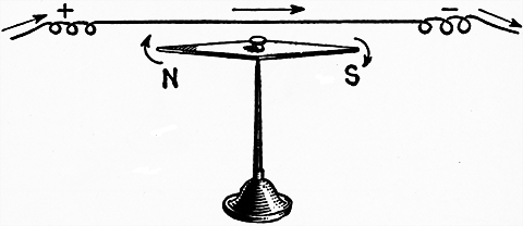
Fig. 503.--Effect of neighboring current upon a magnetic needle. Above the needle and parallel to it is a conductor carrying an electric current, the current flowing in the direction indicated by the arrow. This causes the north pole of the needle to turn toward the east. If the conductor be held below the needle, its north pole will turn in the opposite direction or toward the west. These movements are easily determined by Ampere's rule as follows: If a man could swim in the conductor with the current, and turn to face the needle, then the north pole of the needle will be deflected toward his left hand.
[432] Ques. Describe a simple galvanometer.
Ans. It consists essentially of a magnetic needle suspended within a coil of wire, and free to swing over the face of a graduated dial.
Ques. What is a galvanoscope and how does it differ from a galvanometer?
Ans. A galvanoscope, as shown in fig. 504, serves merely to indicate the presence of an electric current without measuring its strength. It is an indicator of currents where the movement of the needle shows the direction of the current, and indicates whether it is a strong or a weak one. When the value of the readings has been determined by experiment or calculation any galvanoscope becomes a galvanometer.
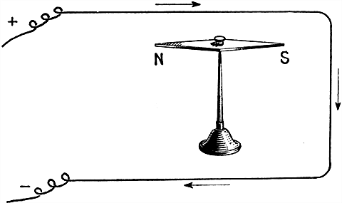
Fig. 504.--Effect upon a magnetic needle of a neighboring current in a loop. In this arrangement the same conductor is simply carried back beneath the needle and hence both the upper and lower portions tend to turn it in the same direction, while the side branch or vertical section is ineffective. In accordance with Ampere's swimming rule, the upper wire causes the N pole of the needle to turn to the left, while if a man can imagine himself swimming in the lower wire in the direction of the current, and facing the needle (that is, swimming on his back), the N pole of the needle will turn to his left--that is to the east. The effect of the loop then has double the effect of the single wire in fig. 503.
[433] Ques. For what use are galvanometers employed?
Ans. They are used for detecting the presence of an electric current, and for determining its direction and strength.
Ques. How is the direction and strength of the current indicated?
Ans. When a galvanometer is connected in a circuit, the direction of the current is indicated by the side towards which the north pole of the needle moves, and the current strength by the extent of the needle's deflection.
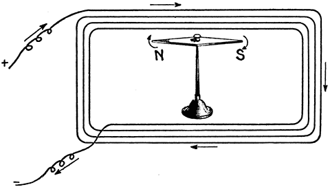
Fig. 505.--Effect upon a magnetic needle of a neighboring current in a coil. The coil as shown, is equivalent to several loops, that is, the force tending to deflect the needle is equal to that of a single loop multiplied by the number of turns. Hence, by using a coil with a large number of turns, a galvanometer may be made very sensitive so that the needle will be perceptibly deflected by very feeble currents. An instrument, as shown in the figure is called a galvanoscope. When it is accurately constructed, and supplied with a scale showing how many degrees the needle is deflected it is then called a galvanometer.
Ques. How should a galvanometer be set up before using?
Ans. When no current is flowing, the coil should be parallel to the magnetic needle when at rest.
[434] Ques. What is a "sensitive" galvanometer?
Ans. One which requires a very small current or pressure to produce a stated deflection.
It does not follow that a galvanometer which is sensitive for current measurement will also be sensitive for pressure measurement.
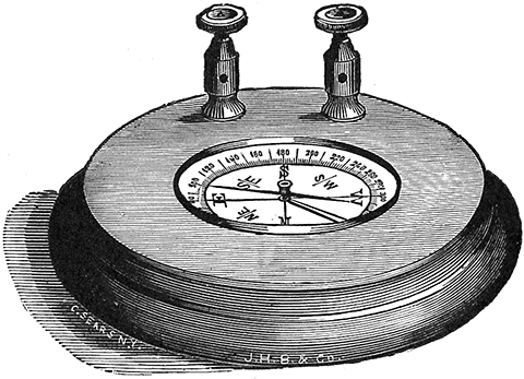
Fig. 506.--Bunnell simple detector galvanometer. It has middle clamps and scale divided into degrees.
Ques. Define the term "sensibility."
Ans. With reference to mirror reflecting galvanometers it may be defined in three ways. First, in megohms, the sensibility being the number of megohms through which one volt will produce a deflection of one millimeter with the scale at one meter distance. Second, in micro-volts, the sensibility being the number of micro-volts which applied directly to the terminals of the galvanometer will produce a deflection of one millimeter on a scale one meter from mirror. The sensibility is best stated in megohms for high resistance galvanometers and in micro-volts for low resistance galvanometers, and is frequently given both for galvanometers for intermediate resistance. Third, in [435] micro-amperes, the sensibility being the number of micro-amperes that will give one millimeter deflection with scale at a distance of one meter.
Ques. Upon what does the sensibility depend?
Ans. 1, Upon the number of times the current circulates around the coil, 2, the distance of the needle from the coil, 3, the weight of the needle, 4, the current strength, and 5, the amount of friction produced by its movement.
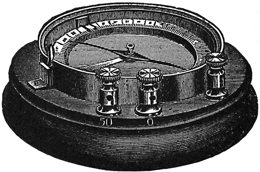
Fig. 508.--Bunnell horizontal galvanometer. It has two coils, one of which is of zero resistance and one of fifty ohms resistance adapting it to a variety of test.
The needle is usually quite small, and often a compound one. In very sensitive galvanometers, the coils are wound with thousands of turns of very fine wire, and shunts are generally used in connection with them.
NOTE.--Strong currents must not be passed through very sensitive galvanometers, for even if they be not ruined, the deflections of the needle will be too large to give accurate measurements. In such cases the galvanometer is used with a shunt, or coil of wire arranged so that the greater part of the current will flow through it, and only a small portion through the galvanometer.
Ques. What two kinds of coil are used?
Ans. The short coil and the long coil.
[436] Ques. What is the difference between a short coil and a long coil galvanometer?
Ans. A short coil galvanometer has a coil consisting of a few turns of heavy wire; a long coil galvanometer is wound with a large number of turns of fine wire.
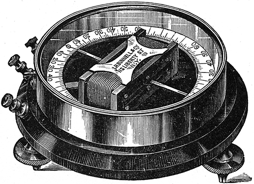
Fig. 509.--Bunnell galvanometer for measurements of instruments, lines, batteries, wires and any object from 1/100 to 10,000 ohms or more.
Ques. What is the action of short and long coil galvanometers?
Ans. With a given current, the total magnetizing force which deflects the needle is the same, but with a short coil, it is produced by a large current circulating around a few turns, instead of a small current circulating around thousands of turns as in the long coil. The short coil being of low resistance is used to measure the current, and the long coil with high resistance, is suitable for measuring the pressure. Hence, a short coil instrument with its scale directly graduated in amperes is an ammeter, and the long coil type with graduation in volts is a voltmeter.
[437] Classes of Galvanometer.--There are numerous kinds of galvanometer designed to meet the varied requirements. According to construction, galvanometers may be divided into two classes, as those having:
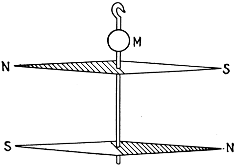
Fig. 510.--Astatic needles. Two magnetic needles of equal moment are mounted in opposition on a light support. The whole system is suspended by a delicate fibre, and when placed in a uniform magnetic field such as that of the earth, there will be no tendency to assume any fixed direction, the only restraining influence on the needles being that due to torsion in the suspension fibre.
Either type may be constructed with short or long coil, and there are several ways in which the deflections are indicated. The principal forms of galvanometer are as follows:
[438] Astatic Galvanometer.--It has been pointed out how a compass needle is affected when a wire carrying a current is held over or under it, the needle being turned in one direction in the first instance, and in the opposite direction for the second position of the wire.
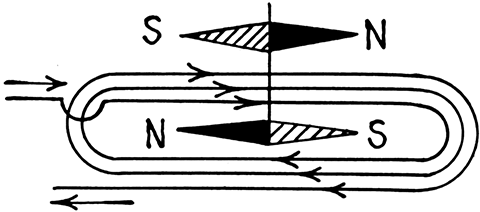
Fig. 511.--Connections of single coil astatic needles. The coil surrounds the lower needle and the direction of the current between the two needles tends to turn them the same way.
The earth's magnetism naturally holds the compass needle north and south. The magnetic field encircling the wire, being at right angles to the needle (when the wire itself is parallel therewith), operates to turn it from its normal position, north and south, so as to set it partially east and west. However, on account of the fact that the earth's magnetism does exert some force tending to hold the needle north and south, it is evident that no matter how strong the current, the latter can never succeed in turning the needle entirely east and west. The accomplishment of this is further prevented by the reason of the points of the needle, where the magnetic effect is greatest, quickly passing out of the reach of the magnetic field, where it is now practically operated on only in a slight degree. Thus it would take quite a powerful current to hold the needle deflected any appreciable distance. The use of a shorter needle is, therefore, more desirable.
[439] It is evident in this style of instrument that the effect of the current cannot be accurately measured, because it acts in opposition to the earth's magnetism, and as this is constantly varying, some method must be employed which will either destroy the earth's magnetism or else neutralize it.
In the astatic galvanometer, the earth's magnetism is neutralized by means of astatic needles. These consist of a combination of two magnetic needles of equal size and strength, connected rigidly together with their poles pointing in opposite and parallel directions, as shown in fig. 510. As the north pole of the earth attracts the south pole of one of the needles, it repels with equal strength the north pole of the other needle, hence, the combination is independent of the earth's magnetism and will remain at rest in any position.
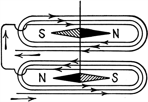
Fig. 512.--Connections of double coil astatic needles. With this arrangement, the direction of current in both coils will tend to turn the system in the same direction, making the needles more sensitive than with a single coil as in fig. 511.
If one of the needles be surrounded by a coil, as shown in fig. 511, the magnetic effect of the current will be correctly indicated by the deflection of the needle.
[440] Sometimes each needle is surrounded by a coil, as in fig. 512, the coils being so connected that the direction of current in each will tend to deflect the needles in the same direction.
Ques. For what use is the astatic galvanometer adapted?
Ans. For the detection of small currents.
It is used in the "nil" or zero methods, in which the current between the points to which the galvanometer is connected is reduced to zero.
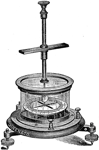
Fig. 513.--Queen reflecting astatic galvanometer. It is mounted on a mahogany base with levelling screws. A plain mirror is attached above the upper needle. The entire combination of mirror and needles is suspended by unspun silk from the interior of a brass tube, which also carries a weak controlling magnet. A dial 4 inches in diameter and graduated in degrees, enables the deflections of the needle to be accurately read. The mirror can be used with a reading telescope and scale, or by means of a lantern, the image of a slit may be reflected from the mirror to a screen. Resistance, .5 to 1,000 ohms.
Ques. Upon what does the movement of the needles depend?
Ans. Upon the combined effect of the magnetic attraction of the current which tends to deflect the needles, and the torsion [441] in the suspension fibre which tends to keep the needle at the zero position.
Ques. Does the astatic galvanometer give correct readings for different values of the current?
Ans. When the deflections are small (that is, less than 10° or 15°), they are very nearly proportional to the strength of the currents that produce them.
Thus, if a current produce a deflection of 6° it is known to be approximately three times as strong as a current which only turns the needle through 2°. But this approximate proportion ceases to be true if the deflection be more than 15° or 20°.
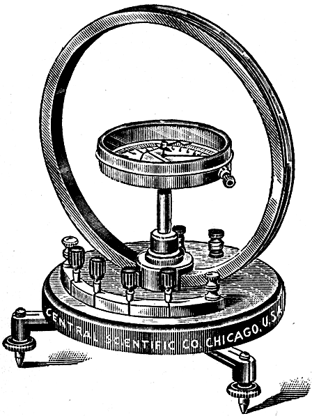
Fig. 514.--Central Scientific Co. tangent galvanometer. A 9 inch brass ring is mounted on a mahogany base which rotates on a tripod provided with levelling screws. The needle has an aluminum pointer and jewelled bearing. The winding consists of 300 turns of magnet wire so connected to the plugs in front that 20, 40, 80, or 160 turns or any combination of these numbers may be used. For heavy currents a band of copper is used by connecting to the extra pair of binding posts in the rear of the instrument.
Ques. Why does the instrument not give accurate readings for large deflections?
Ans. The needles are not so advantageously acted upon by the current, since the poles are no longer within the coils, but [442] protrude at the side. Moreover, the needles being oblique to the force acting on them, part only of the force is turning them against the directive force of the fibre; the other part is uselessly pulling or pushing them along their length.
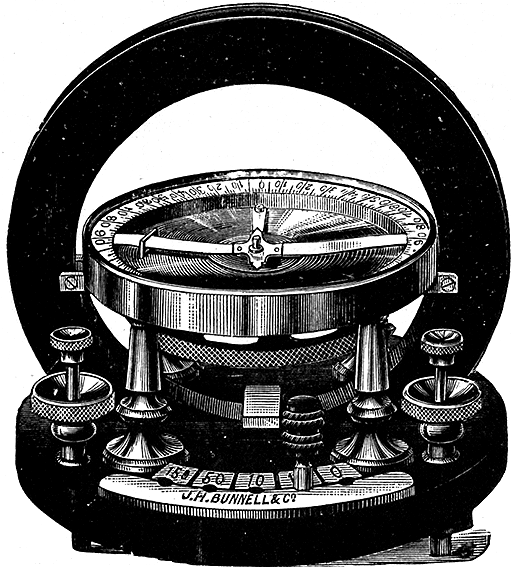
Fig. 515.--Bunnell tangent galvanometer. This instrument is mounted on a circular hard rubber base, 7-3/8 inches diameter, provided with levelling screws and anchoring points. The galvanometer consists of a magnetized needle 7/8 inch in length, suspended at the center of a rubber ring six inches in diameter, containing the coils. There are five coils of 0, 1, 10, 50 and 150 ohms resistance. The first is a stout copper band of inappreciable resistance; the others are of different sized copper wires, carefully insulated. Five terminals are provided, marked, respectively, 0, 1, 10, 50 and 150. The ends of the coils are so arranged that the plug inserted at the terminal marked 50 puts in circuit all the coils; marked at the terminal 50--all except the 150 ohm coil; and so on, till at the zero terminal only the copper band is in circuit. Fixed to the needle, which is balanced on jewel and point, is an aluminum pointer at right angles, extending across a five inch dial immediately beneath. One side of the dial is divided into degrees; on the other side, the graduations correspond to the tangent of the angles of deflection.
Ques. How may correct readings be obtained?
Ans. The instrument may be calibrated, that is, it may be ascertained by special measurements, or by comparison with a [443] standard instrument, the amounts of deflection corresponding to particular current strengths.
Thus, if it be once known that a deflection of 32° on a particular galvanometer is produced by a current of 1/100 of an ampere, then a current of that strength will always produce on that instrument the same deflection, unless from any accident the torsion force or the intensity of the magnetic field be altered.
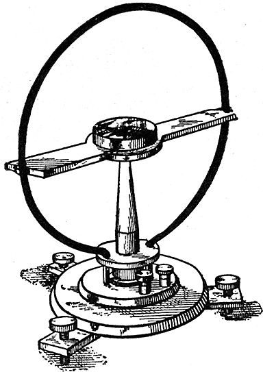
Fig. 516.--Tangent galvanometer. It consists of a short magnetic needle suspended at the center of a coil of large diameter and small cross section. In practice, the diameter of the coil is about 17 times the length of the needle. If the instrument be so placed that, when there is no current in the coil, the suspended magnet lies in the plane of the coil, that is, if the plane of the coil be set in the magnetic meridian, then the current passing through the coil is proportional to the tangent of the angle by which the magnet is deflected from the plane of the coil, or zero position--hence the name: "tangent galvanometer."
The Tangent Galvanometer.--It is not possible to construct a galvanometer in which the angle (as measured in degrees of arc) through which the needle is deflected is proportional throughout its whole range to the strength of the current. But it is possible to construct a very simple galvanometer in which the tangent of the angle of deflection shall be accurately proportional to the strength of the current.

Fig. 517.--Horizontal section through middle of tangent galvanometer, showing magnetic whirls around the coil and corresponding deflection of needle.
A simple form of tangent galvanometer is shown in fig. 516. The coil of this instrument consists of a simple circle of stout copper wire from ten to fifteen inches in diameter. At the center is delicately suspended a magnetized steel needle not exceeding one inch in length, and usually furnished with a light index of aluminum. When the galvanometer is in use, the plane of the ring must be vertical and in the magnetic meridian. A horizontal section through the middle of the instrument is shown in fig. 517. For simplicity, the coil is supposed to have but a single turn of wire, the circles surrounding the wire representing the magnetic lines of force. By extending the lines of force until they reach the needle, it will be seen that with a short needle, the [445] deflecting force acts in an east and west direction when the galvanometer is placed with its coil in the magnetic meridian.
If, in fig. 518, ab represent the deflecting force acting on the N end of the needle, the component of this force that acts at a right angle to the needle will be
in which, x is the angle of the deflection.
The controlling force is
and when the needle is in equilibrium, the component ae = H sin x is equal and opposite to ac, hence
from which
Since ab is proportional to the current,
[446] in which k is a constant depending upon the instrument. For any other current C',
hence
This means that the currents passing through the coil of a tangent galvanometer are proportional, not to the angle of deflection, but to the tangent of that angle.
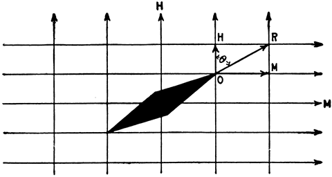
Fig. 519.--Diagram illustrating the tangent law. This is the law of the combined action of two magnetic fields upon a magnetic needle. If two magnetic fields be at right angles in direction as indicated in the figure, the resultant field is obtained by the parallelogram of forces and it makes an angle θ with one of the component fields such that tan θ = M + H where M and H are the strengths of the component fields. In the tangent galvanometer this principle is employed in the measurement of currents. A magnetic needle is pivoted in a field of known strength. The current to be measured is passed round a coil (or coils) which generates a field at right angles to the original field. The needle then lies along the direction of the resultant field, and by finding the tangent of its angle of deflection, and knowing the field strength produced by unit current in the coil, the current strength can be found.

Fig. 520.--Graduation of tangent galvanometer scale with divisions representing tangent values. In the figure let a tangent OT be drawn to the circle, and along this line let any number of equal divisions be set off, beginning at O. From these points draw lines back to the center. The circle will thus be divided into a number of spaces, of which those near O are nearly equal, but which get smaller and smaller as they recede from O. These unequal spaces correspond to equal increments of the tangent. If the scale were divided thus, the readings would be proportional to the tangents.
Ques. Upon what does the sensibility of a tangent galvanometer depend?
Ans. It is directly proportional to the number of turns of the coil and inversely proportional to the diameter of the coil.
Ques. How may the tangent galvanometer be used as an ammeter?
Ans. The strength of the current may be calculated in amperes by the formula given below when the dimensions of the instrument are known.
The needle is supposed to be subject to only the earth's magnetism and to move in a horizontal plane. The current is calculated as follows:
amperes = ((H × r)/N) tan x(1)
[447] in which
The constant H, given in the following table represents the horizontal force of the earth's magnetism for the place where the galvanometer is used. Each value has been multiplied by (2π )/10 so that the formula (1) for amperes is correct as given.
Table of Galvanometer Constants.--Values of H.
| Boston | .699 |
| Chicago | .759 |
| Denver | .919 |
| Jacksonville | 1.094 |
| London | .745 |
| Minneapolis | .681 |
| New York | .744 |
| New Haven | .731 |
| Philadelphia | .783 |
| Portland, Me. | .674 |
| San Francisco | 1.021 |
| St. Louis | .871 |
| Washington | .810 |
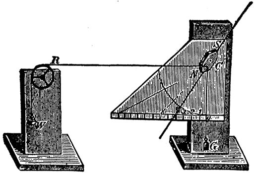
Fig. 521.--Mechanical explanation of the tangent law. Construct an apparatus as shown in the figure. The short wooden block, NS, represents the magnetic needle. This piece of wood turns around its center, C, which may be an ordinary nail. It will now be seen that two different forces act upon N; namely, the weight, G (one or two ounces), and the changeable weights which are placed in the scoop, W (made of cardboard). The height of the roll, or wheel, R, is such that the cord, RN, runs horizontally, when NS stands vertically, i.e., when there is no weight in the little scoop. If the wheel, R, be placed sufficiently far from NS, the string RN, will always remain almost horizontal, even if NS be deviated. The thin hand on NS moves over a vertical scale, which is divided into equal parts, as shown. This scale may be made of cardboard. If the hand point to division 1 when one ounce is placed in the scoop, it will point to 2 for two ounces, to 3 for three ounces, etc. At 45° the needle is deviated at its greatest angle, and this is, therefore, the sensitivity angle of the tangent galvanometer. The deviating values are, therefore, proportionate to the scale parts 01, 02, and 03, and so on; and, inasmuch as these themselves are tangents, the tangent law will hold good.
[448] Ques. How is the tangent galvanometer constructed to give direct readings?
Ans. To obviate reference to a table, the circular scale of the instrument is sometimes graduated into tangent values, as in fig. 520, instead of being divided into equal degrees.
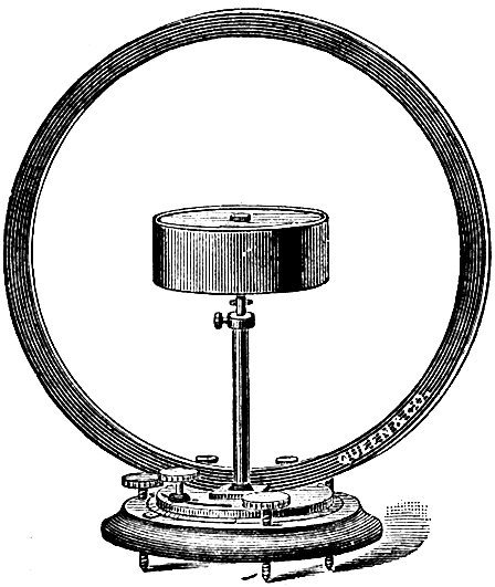
Fig. 522.--Queen tangent and sine galvanometer. This instrument properly adjusted can be used as a standard instrument for laboratory work. The brass ring is 12 inches in diameter, and the grooves in which the wire is wound are carefully turned so as to be of true rectangular cross section, thus allowing the constant of the instrument to be accurately calculated and compared with the constant as obtained by other methods. The compass box is 5 inches in diameter and is so held in position that it may be raised or lowered, rotated on its vertical axis, shifted out of the plane of the coil, etc., thus enabling the operator to acquire proficiency with the instrument and to meet all cases of derangement possible. The dial is graduated to single degrees, and the needle is suspended by a very light cocoon fibre. The whole instrument can be turned about its vertical axis, and a quadrant graduated in degrees upon the base allows the amount of rotation to be accurately measured, and the laws of the sine galvanometer investigated. The instrument is wound to measure .25 ampere to 8 amperes.
Ques. What is the objection to the scale with tangent values?
Ans. It is more difficult to divide an arc into tangent lines with accuracy than into equal degrees.
Ques. What disadvantage has the tangent galvanometer?
Ans. The coil being much larger than the needle, and hence far away from it, reduces the sensitiveness of the instrument.
[449] The Sine Galvanometer.--This type of instrument has a vertical coil which may be rotated around a vertical axis, so that it can be made to follow the magnetic needle in its deflections.
In the sine galvanometer, the coil is moved so as to follow the needle until it is parallel with the coil. Under these circumstances, the strength of the deflecting current is proportional to sine of angle of deflection.
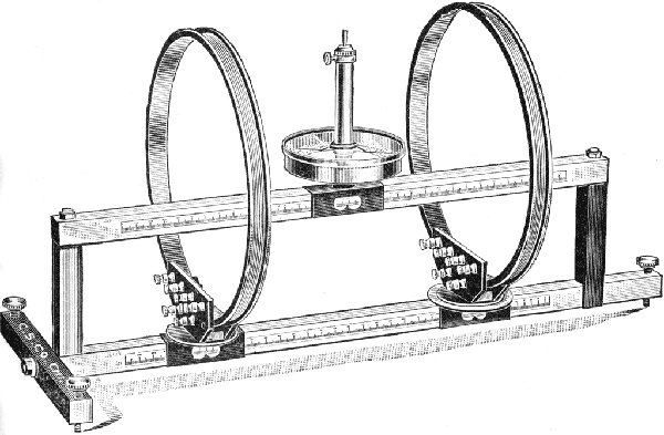
Fig. 523.--Central Scientific Co. universal tangent galvanometer. This instrument may be used as a tangent, Gaugain, Helmholtz-Gaugain, sine, cosine, Wiedemann or detector galvanometer. The coils, which slide on a beam parallel to the one carrying the needle box, are wound on brass rings 12 inches in diameter. On each ring are wound two coils of 48 turns each, connected to separate binding posts, and double wound so as to be of equal resistance. The coils and needle box are each provided with an indicator for reading their position on the scale. The needle box is swivelled and removable and one coil may be rotated about its vertical axis and its position read on a disc graduated in degrees. Currents may be measured ranging from .000002 ampere to 100 amperes.
Ques. Describe the construction of a sine galvanometer.
Ans. A form of sine galvanometer is shown in fig. 524. The vertical wire coil is seen at M. A needle of any length less than the diameter of the coil M, moves over the graduated circle N. The coil M, and graduated circle N may be rotated on a vertical [450] axis, and the amount of angular movement necessary to bring the needle to zero, measured on the graduated circle H.
Ques. How is the current strength measured?
Ans. It is proportional to the sine of the angle measured on the horizontal circle H, through which it is necessary to turn the coil M, from the plane of the earth's magnetic meridian to the plane of the needle when it is not further deflected by the current.
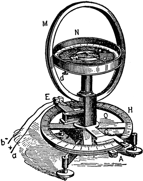
Fig. 524.--Sine galvanometer. It differs from the tangent galvanometer in that the vertical coil and magnetic needle are mounted upon a standard free to revolve around a vertical axis, with provision for determining the angular position of the coil. The needle may be of any length shorter than the diameter of the coil. In the figure the parts are: M, coil; N, graduated dial of magnetic needle; H, graduated dial by which the amount of rotation necessary to bring the needle to zero is measured; E, terminals of the coil; O, upright standard carrying coil and graduated dial of magnetic needle; C, base with levelling screws.
Ques. How is the sine galvanometer operated?
Ans. In using the instrument, after the needle has been set to zero, the current is sent through the coil, producing a deflection of the needle. The coil is then rotated to follow the motion [451] of the needle, the current being kept constant, the rotation being continued until the zero on the upper dial again registers with the needle. The current then is proportional to the sine of the angle through which the coil has been turned, as determined by the lower dial.
Ques. Has the sine galvanometer a large range?
Ans. For a given controlling field, it does not admit of a very large range of current measurement, since, for large deflection, on rotating the coil the position of instability is soon reached.
TABLE OF NATURAL SINES AND TANGENTS
| Angle | Sin. | Tan. |
| 0° | .0000 | .0000 |
| 1 | .0175 | .0175 |
| 2 | .0349 | .0349 |
| 3 | .0523 | .0524 |
| 4 | .0698 | .0699 |
| 5 | .0871 | .0875 |
| 6 | .1045 | .1051 |
| 7 | .1219 | .1228 |
| 8 | .1392 | .1405 |
| 9 | .1564 | .1564 |
| 10° | .1736 | .1763 |
| 11 | .1908 | .1944 |
| 12 | .2079 | .2126 |
| 13 | .2250 | .2309 |
| 14 | .2419 | .2493 |
| 15 | .2588 | .2679 |
| 16 | .2756 | .2867 |
| 17 | .2924 | .3057 |
| 18 | .3090 | .3249 |
| 19 | .3256 | .3443 |
| 20° | .3420 | .3640 |
| 21 | .3584 | .3839 |
| 22 | .3746 | .4040 |
| 23 | .3907 | .4245 |
| 24 | .4067 | .4452 |
| 25 | .4226 | .4663 |
| 26 | .4384 | .4877 |
| 27 | .4540 | .5095 |
| 28 | .4695 | .5317 |
| 29 | .4848 | .5543 |
| 30° | .5000 | .5774 |
| 31 | .5150 | .6009 |
| 32 | .5299 | .6249 |
| 33 | .5446 | .6494 |
| 34 | .5592 | .6745 |
| 35 | .5736 | .7002 |
| 36 | .5878 | .7265 |
| 37 | .6018 | .7536 |
| 38 | .6157 | .7813 |
| 39 | .6293 | .8098 |
| 40° | .6428 | .8391 |
| 41 | .6561 | .8693 |
| 42 | .6691 | .9004 |
| 43 | .6820 | .9325 |
| 44 | .6947 | .9657 |
| 45 | .7071 | 1.0000 |
| 46 | .7193 | 1.0355 |
| 47 | .7314 | 1.0724 |
| 48 | .7431 | 1.1106 |
| 49 | .7547 | 1.1504 |
| 50° | .7660 | 1.1918 |
| 51 | .7771 | 1.2349 |
| 52 | .7880 | 1.2799 |
| 53 | .7986 | 1.3270 |
| 54 | .8090 | 1.3764 |
| 55 | .8192 | 1.4281 |
| 56 | .8290 | 1.4826 |
| 57 | .8387 | 1.5399 |
| 58 | .8480 | 1.6003 |
| 59 | .8572 | 1.6643 |
| 60° | .8660 | 1.7321 |
| 61 | .8746 | 1.8040 |
| 62 | .8829 | 1.8807 |
| 63 | .8910 | 1.9626 |
| 64 | .8988 | 2.0503 |
| 65 | .9063 | 2.1445 |
| 66 | .9135 | 2.2460 |
| 67 | .9205 | 2.3559 |
| 68 | .9272 | 2.4751 |
| 69 | .9339 | 2.6051 |
| 70° | .9397 | 2.7475 |
| 71 | .9455 | 2.9042 |
| 72 | .9511 | 3.0772 |
| 73 | .9563 | 3.2709 |
| 74 | .9613 | 3.4874 |
| 75 | .9659 | 3.7321 |
| 76 | .9703 | 4.0108 |
| 77 | .9744 | 4.3315 |
| 78 | .9781 | 4.7046 |
| 79 | .9816 | 5.1446 |
| 80° | .9848 | 5.6713 |
| 81 | .9877 | 6.3138 |
| 82 | .9903 | 7.1154 |
| 83 | .9925 | 8.1443 |
| 84 | .9945 | 9.5144 |
| 85 | .9962 | 11.43 |
| 86 | .9976 | 14.30 |
| 87 | .9986 | 19.08 |
| 88 | .9994 | 28.64 |
| 89 | .9998 | 57.29 |
Ques. What is the position of instability?
Ans. The position of the needle beyond which the rotation of the coil will cause it to turn all the way round.
Ques. How may the range be increased?
Ans. By an adjustable controlling field or a shunt.
[452] Ques. What advantage has the sine galvanometer over the tangent instrument?
Ans. Its advantage is in the case where the relative values of two or more currents are required to be measured, or where the constant of the instrument is obtained by comparison with a standard measuring instrument and not calculated from the dimensions of the coil, because all galvanometers thus used follow the sine law independently of the shape of the coil, while only circular coils will follow the sine law.
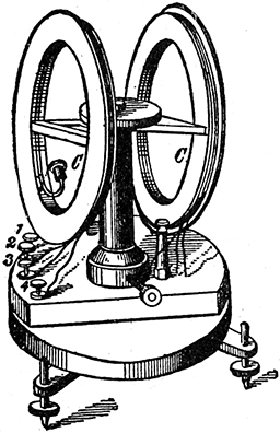
Fig. 525.--Differential galvanometer. It consists of two coils of wire, so wound as to have opposite magnetic effects on a magnetic needle suspended centrally between them. The needle of a differential galvanometer shows no deflection when two equal currents are sent through the coils in opposite directions, since, under these conditions, each coil neutralizes the effect of the other. Sometimes the current is so sent through the two coils, that each coil deflects the needle in the same direction. In this case the instrument is no longer differential in action. If, when this condition obtains, the magnetic needle be suspended at the exact center of the line which joins the centers of the coils, the advantage is gained by obtaining a field of more nearly uniform intensity around the needle. When the needle is suspended by a silk fibre, a final and most delicate adjustment can be obtained by raising or lowering one of the levelling screws slightly, so as to tilt the needle nearer to or farther from one of the coils.
The Differential Galvanometer.--This is a form of galvanometer in which a magnetic needle is suspended between two coils of equal resistance so wound as to tend to deflect the needle in opposite directions. The needle of a differential galvanometer [453] shows no deflection when two equal currents are sent through the coils in opposite directions, since under these conditions, each coil neutralizes the other's effects. Such instruments may be used in comparing resistances, although the Wheatstone bridge, in most cases, affords a preferable method.
Ques. What is the special use of the differential galvanometer?
Ans. It is used for comparing two currents.
Ques. What is the method of comparing currents?
Ans. If two equal currents be sent in opposite directions through the coils of the galvanometer, the needle will not move; if the currents be unequal, the needle will be deflected by the stronger of them with an intensity corresponding to the difference of the strengths of the two currents.
Ques. How are the coils adjusted?
Ans. This is done by coupling them in series in such a way that they tend to turn the needle in opposite directions, and when a current is passing through them, they are moved nearer to the needle or farther from it until the needle stands at zero with any current.
If the coils be not movable, a turn or more can be unwound from the coil giving the greatest magnetic effect until a balance is obtained, the wire so unwound can then be coiled in the base of the instrument.
Ballistic Galvanometer.--This type of galvanometer is designed to measure the strength of momentary currents, such for instance, as the discharge of a condenser. In construction the magnetic system is given considerable weight, and arranged to give the least possible damping effect.
[454] The term "damping effect" means the offering of a retarding force to control swinging vibrations, such as the movements of a galvanometer needle, and to bring them quickly to rest.
If a momentary current be passed through a ballistic galvanometer, the impulse given to the needle does not cause appreciable movement to the magnetic system until the current ceases, owing to the inertia of the heavy moving parts, the result being a slow swing of the needle.
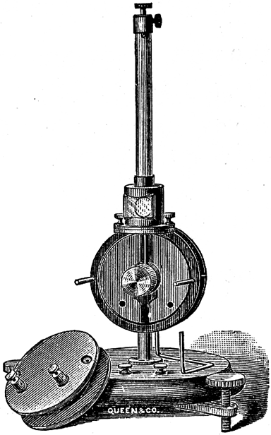
Fig. 526.--Queen dead beat and ballistic reflecting galvanometer. As illustrated, the coils are easily removable and enclose a heavy block of copper fixed in a central fork. In a cylindrical hole bored in this block hangs the bell magnet which with its mirror is suspended by a long cocoon fibre, and the eddy currents induced in the copper bring the system quickly to rest after a deflection. By lifting the copper block out of the frame the instrument is made ballistic. The instrument is made with coils of any desired resistance up to 1,000 ohms.
Ques. What name is given to the swing of a ballistic galvanometer needle?
Ans. It is called the kick.
Ques. How is the current measured?
Ans. As the needle swings slowly around it adds up, as it [455] were, the varying impulses received during the passage of the momentary current, and the quantity of electricity that has passed is proportional to the sine of half the angle of the first swing or kick.
If a reflecting method be used with a straight scale, the observed deflection depends upon the tangent of twice the angle of movement of the needle. For small deflections, however, the change of flux can be taken as directly proportional to the observed deflection.
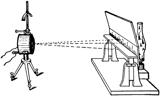
Fig. 527.--Thompson galvanometer with mirror reflecting system for reading the deflections of a galvanometer needle by the movements of a spot of light reflected from a mirror attached to the needle or movable magnetic system.
Use of Mirrors in Galvanometers.--In order that small currents may be measured accurately, some means must be provided to easily read a small deflection of the needle. Accordingly, it is desirable that the pointer be very long so that a large number of scale divisions may correspond to small deflections. In construction, since sensitive galvanometers must be made with the moving parts of little weight, it would not do to use a long needle, hence a ray of light is used instead, which is reflected on a distant scale by a small mirror attached to the moving part.
[456] In the Thompson mirror reflecting galvanometer, as shown in fig. 528, a small vertical slit is cut in the lamp screen below the scale, and the ray of light from the lamp, passing through the slit, strikes the mirror which is about three feet distant, and which reflects the beam back to the scale. It should be noted that the angle between the original ray of light and the reflected ray is twice the angle of the deflection of the mirror; the deflections of the ray of light on the scale, however, are practically proportional to the strength of currents through the instrument. The mirror arrangement as shown in fig. 528, requires a darkened room for its operation, but such is not necessary when a telescope is used as in fig. 529. Here the scale readings are reflected in the mirror and their value observed by the telescope without artificial light.
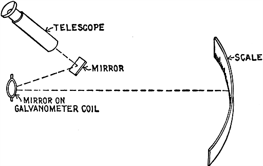
Fig. 528.--Telescope method of reading galvanometer deflections by reflection of scale reading in mirror. Here two mirrors are used, but in most cases the telescope is pointed directly toward the mirror on galvanometer shown in fig. 527, because the two mirror system, as illustrated in the figure, is used on portable galvanometers since it is the more compact.
Damping.--This relates to the checking or reduction of oscillations. Thus, a galvanometer is said to be damped when so constructed that any oscillations of the pointer which may be started, rapidly die away. Galvanometers are frequently provided with damping devices for the purpose of annulling these [457] oscillations, thus causing the moving part to assume its final position as quickly as possible.
Sometimes the instrument is fitted with a damping coil, or closed coil so arranged with respect to the moving system that the oscillations of the latter give rise to electric currents in the closed coil, whereby energy is dissipated. Again, air vanes are employed, but anything in the nature of solid friction cannot be used.
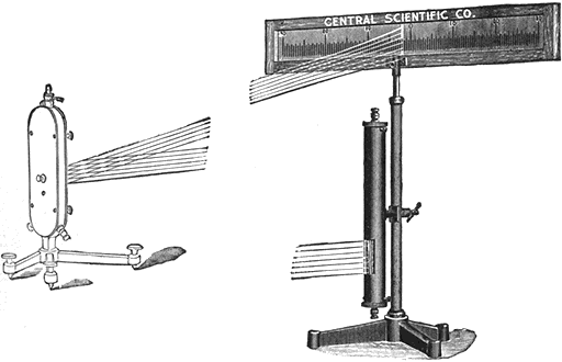
Figs. 529 and 530.--Galvanometer lamp and scale for individual use. The scale is etched on a ground glass strip 6 centimeters wide by 60 centimeters long with long centimeter divisions and short millimeter divisions the entire length, reading both ways from zero in the center. It is mounted in an adjustable wooden frame. A straight filament lamp (110 volts) is enclosed in a metal hood japanned black to cut out all reflected light. This form of filament makes a single brilliant line on the scale, enabling closer readings than the "spot of light" arrangement. The lamp hood is adjustable to any desired height on the support rod.
D'Arsonval Galvanometer.--This instrument has a movable coil in place of a needle, and its operation depends upon the principle that if a flat coil of wire be suspended with its axis perpendicular to a strong magnetic field, it will be deflected whenever a current of electricity passes through it.
[458] Ques. Describe the construction of a D'Arsonval galvanometer.
Ans. The essential features are shown in figs. 532 and 533. The coil, which is rectangular in section is wound upon a copper form, and suspended between a permanent magnet by fine wires to the points A and B. The magnet has its poles at N and S. It is a soft iron cylinder fixed between the poles in order to intensify the magnetic field across the air gaps in which the coil moves.
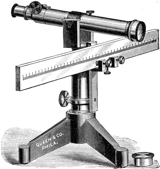
Fig. 531.--Queen reading telescope. This arrangement is utilized to measure the deflections of a galvanometer having suspended mirror moving system. It consists of a reading telescope mounted as illustrated with a millimeter scale, having a length of 50 centimeters. In use, the image of the scale is seen in the galvanometer mirror through the telescope. The eye piece of the telescope has a cross hair which acts as a reference line so that by noting the particular division on the scale when the galvanometer is at rest, the amount of deflection can be readily observed when the galvanometer is deflected. The instrument has all the necessary adjustments to set it up quickly and for bringing the cross hair and scale in focus. It is generally placed at a distance of one meter from the galvanometer mirror.
Ques. Explain its operation.
Ans. An enlarged horizontal cross section of the galvanometer on line XY is shown in fig. 533. The current is flowing in the coil as in fig. 532, up on the left side and down on the right. [459] The position of the coil when no current is flowing is indicated by n' s'. By applying the law of mutual action between magnetic poles, it is seen that when the current is applied, the poles developed at n' s' will move into the position n'' s''. See fig. 119.
Ques. How is the coil affected by a change in the direction of the current?
Ans. The polarity of the coil is reversed and consequently the direction of the deflection.
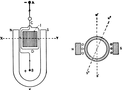
Figs. 532 and 533.--Diagrams showing essential features of construction and principle of operation of D'Arsonval galvanometer.
Ques. Upon what does the sensitiveness of the instrument depend?
Ans. Upon the strength of the field of the permanent magnet, the number of turns in the suspended coil, and the torsion of the wires by which it is suspended.
Ques. When is this galvanometer called "dead beat"?
Ans. When the construction is such that the moving part comes quickly to rest without a series of diminishing vibrations.
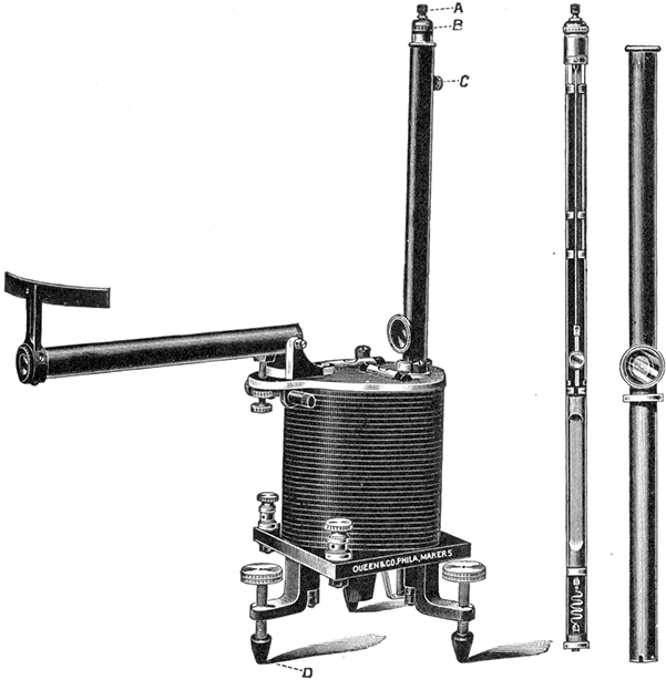
Figs. 534 to 536.--Queen horizontal magnet D'Arsonval galvanometer with telescope and scale. It is very sensitive and is used in many electrical measurements, including commercial testing, such as measuring insulation of cables, fault location, etc. It is not affected by surrounding magnetic disturbances, and may, therefore, be used in proximity to dynamos and switchboards. The instrument has a pair of binding post terminals, one of which connects to a bottom spiral of the system and the other forms a junction with the top of the tube holding the system, forming a complete circuit through the coil. The tube containing the system may be readily removed from the magnet and another tube having a different system inserted as is required for various kinds of electrical measurement. The entire system with its suspension may be inspected by the removal of a thumb screw. To inspect interior of tube first be sure that the screw B is turned so that the coil is clamped. Entirely remove screw C, and, holding the outside tube near the window, press firmly with the finger on the extreme top of the suspension support. The inside rib, with complete suspension, will draw from the tube, and the working parts can be fully inspected. Carefully return same to its original position in tube, setting tight the screw C. The galvanometer is designed so that the coil is clamped in position when the galvanometer must be transported. The insulation of the galvanometer terminals and binding posts is such as to guard against any possible leakage. As a further protection, each levelling screw is provided with a hard rubber insulator. This feature is essential since, in making insulation measurements, the operator wishes to be assured that the deflection being obtained is the result of leakage upon the cable or wire being measured and not leakage between the galvanometer terminals. The galvanometer is provided with an attached telescope and scale for noting the deflections. The deflections produced by this galvanometer are proportional to the current. To facilitate quickly setting up the instrument, two way levels are provided.
[461] Ques. What causes this?
Ans. The instrument is made dead beat by winding the coil on a copper or aluminum frame, so that when in operation, currents are induced in the frame by the motion of the coil in the magnetic field; these currents oppose the motion of the coil.
Ques. For what service is the D'Arsonval galvanometer adapted?
Ans. It is desirable for general use as it is not much affected by changes in the magnetic field. It may be made with high enough period and sensibility to be satisfactory as a ballistic instrument, but for extreme sensibility an instrument of the astatic type is more generally used.
Galvanometer "Constant" or "Figure of Merit."--In order that a galvanometer shall be of value as a measuring instrument, the relation between the current and the deflection produced by it must be known. This may be obtained experimentally by determining the value of the current required to produce one scale division. The galvanometer constant then may be defined as the resistance through which the galvanometer will give a deflection of one scale division when the current applied is at a pressure of one volt.
Accordingly, the deflection as indicated on the scale must be multiplied by its constant or figure of merit, in order to obtain the correct reading. If the scale readings be not directly proportional to the quantity to be measured, the law of the instrument must also be considered.
Thus in a tangent galvanometer as previously explained
where I = current, φ the deflection or scale reading, and K the galvanometer constant.
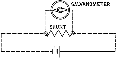
Fig. 537.--Diagram showing method of connecting galvanometer shunt. By the use of a shunt the range of measurement of a galvanometer can be greatly increased.
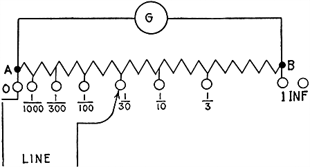
Fig. 538.--Diagram of a form of universal shunt box for use with galvanometers of widely different resistances. The galvanometer, as indicated at G, is connected across the ends of a series of resistances AB. The main wires are connected, one to end A of the series and the other to a travelling point whose position is varied by means of plugs or by a dial switch.
Galvanometer Shunts.--The sensitiveness of a galvanometer used for measuring current may be reduced to any desired extent by connecting a resistance of known value in parallel with it. Thus, if it be desired to measure a current greater than can be [463] measured directly by the galvanometer, a part of the current can be sent through the resistance or shunt, and the total value of the current calculated.
A galvanometer shunt bears a definite ratio to the resistance of the galvanometer, being usually adjusted so that only .1, .01, or .001 part of the current passes through the galvanometer.
The degree in which a shunt increases the range of deflection of a galvanometer is called its "multiplying power."
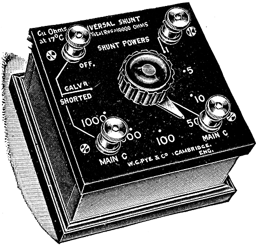
Fig. 539.--Ayrton-Mather universal shunt. This shunt may be used with any galvanometer. The total resistance is 10,000 ohms, with shunt powers of 1, 5, 10, 50, 100, 500, and 1,000. It is also fitted with positions in which the galvanometer is shorted and off. The coils are of constantan wire.
If .1 of the current flowing, passed through the galvanometer and .9 through the shunt, then the current in the circuit would be ten times that through the galvanometer. Accordingly the current in the galvanometer must be multiplied by the multiplying power of the shunt to obtain the true value of the current in the circuit.
In order to determine the resistance necessary to be used with a certain galvanometer, the resistance of the latter is to be divided by the multiplying power desired less one.
[464] EXAMPLE.--What must be the resistance of a shunt for a galvanometer of 2,000 ohms resistance where only one fifth of the current is to pass through the galvanometer?
The multiplying power less one is
and the required resistance is
When it is essential that the total resistance of the circuit should not be altered by an alternation of the galvanometer shunt, a compensating box should be used which automatically inserts a resistance for each shunt in series with the shunted galvanometer to bring the total resistance up equal to the unshunted value. Thus the current in the main circuit is not altered.
The practical electrician frequently has to make tests of various kinds which require the rapid and accurate measurement of voltage, current and resistance. It is therefore essential that he understand the methods employed in testing and the operation of the instruments used.
Most tests are made with a galvanometer, and the devices, such as resistances, switches, etc., which are used in connection with the galvanometer may be obtained put up in a neat and substantial box together with the galvanometer, the combination being called a "testing set." Numerous forms of testing set are illustrated in this chapter.
The construction, use, and operation of the various types of galvanometer have been explained in chapter twenty-six. Ammeters and voltmeters, which are simply special forms of galvanometer, and which are largely used are fully described in the preceding chapter.
Pressure Measurement.--An electromotive force has been defined as that which causes or tends to cause a current; it is analogous to water pressure; potential difference corresponds to difference of level. The total electromotive force of a circuit is [466] independent of resistance or current, and cannot be limited to mean the fall of pressure between any two points, as for instance the terminals of a battery.
If the pressure of a battery be two volts when measured on open circuit by a static voltmeter, there will still be two volts on closed circuit, but there will now be a loss of pressure through the internal resistance of the battery and the voltage across the terminals will be less than the total voltage. The static voltmeter, never closing the circuit, actually measures the total voltage.
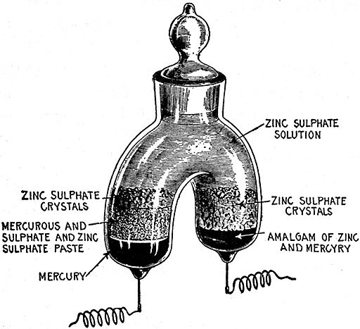
Fig. 540.--Clark cell (Kahle's modification of the Rayleigh H form), the standard for the International volt. The cell has for its positive electrode, mercury, and for its negative electrode, amalgamated zinc. The electrolyte consists of a saturated solution of zinc sulphate and mercurous sulphate. The pressure is 1.434 volts at 15°C., and between 10°C. and 25°C. the pressure decreases .00115 of a volt for each increase of 1°C. The containing glass vessel consists of two limbs, closed at bottom and joined above to a common neck fitted with a ground glass stopper. The diameter of the limbs should be at least 2 cms., and their length at least 3 cms. The neck should be not less than 1.5 cms. in diameter. At the bottom of each limb a platinum wire of about .4 mm. in diameter is sealed through the glass. To set up the cell, place mercury in one limb, and in the other hot liquid amalgam, containing 90 parts mercury and 10 parts zinc. The platinum wires at the bottom must be completely covered by the mercury and the amalgam, respectively. On the mercury, place a layer 1 cm. thick of the zinc and mercurous sulphate paste. Both this paste and the zinc amalgam must be covered with a layer of the neutral zinc sulphate crystals 1 cm. thick. The whole vessel must then be filled with the saturated zinc sulphate solution, and the stopper inserted so that it shall just touch it, leaving, however, a small bubble to guard against breakage when the temperature rises. Before finally inserting the glass stopper a strong alcoholic solution of shellac is applied to the upper edge, after which the stopper is pressed firmly in place.
[467] Ques. What error is introduced in measuring the pressure of a battery with an ordinary voltmeter?
Ans. Since the measurement is made on closed circuit the reading does not give the total pressure of the battery.
The error is very slight because the resistance of the voltmeter is very high and the current so small that the loss of pressure in the battery can be neglected.
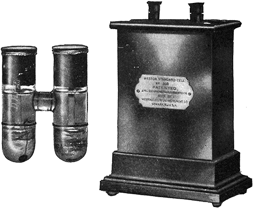
Fig. 541.--Weston Cadmium Cell. It is made in two forms; one known as the Weston normal cell, in which the solution of cadmium sulphate is saturated at all temperatures at which the cell may be used. The other, known as the Weston standard cell, in which the cadmium sulphate solution is unsaturated at all temperatures above 4°C. The Weston normal cell, or saturated form is slightly affected by changes in temperature, but, on account of the fact that it can be accurately reproduced, it was adopted by the London Conference in 1908, as a convenient voltage standard. The value of its voltage suggested by the committee of the London Conference on Electrical Units and Standards, and adopted by the Bureau of Standards at Washington, Jan. 1st, 1911, is 1.0183 International volts at 20°C. At any other temperature its voltage is:
Et = E20 - 0.0000406(t-20) - 0.00000095(t-20)2 + 0.00000001(t-20)3
The Weston standard cell, or unsaturated form is practically unaffected by changes in temperature and is the form most commonly used for laboratory work and general testing. The average pressure of this form is 1.0187 Int. volts.
[468] Ques. Define the International volt.
Ans. It is the electromotive force that, steadily applied to a conductor whose resistance is one International ohm, will produce a current of one International ampere, and which is represented sufficiently well for practical use by 1,000/1,434 of the voltage between the poles of the Clark cell at a temperature of 15° C., when prepared as in fig. 540.
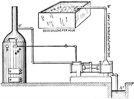
Figs. 542 and 543.--Diagrams showing hydraulic analogy illustrating the difference between amperes and coulombs. The rate of current flow of one ampere in fig. 543 may be compared to the rate of discharge of a pump as in fig. 542. Assuming the pump to be of such size that it discharges a gallon per stroke and is making 60 strokes per minute, the quantity of water discharged per hour (coulombs in fig. 543) is 1 × 60 × 60 = 3,600 gallons. Following the analogy further (in fig. 543), the pressure of one volt is required to force the electricity through the resistance of one ohm between the terminals A and B. In fig. 542, the boiler must furnish steam pressure on the pump piston to overcome the friction (resistance) offered by the pipe and raise the water from the lower level A' to the higher level B'. The difference of pressure between A and B in the electric circuit corresponds to the difference of pressure between A' and B'. The cell furnishes the energy to move the current by maintaining a difference of pressure at its terminals C and D; similarly, the boiler furnishes energy to raise the water by maintaining a difference of pressure between the steam pipe C and exhaust pipe D'.
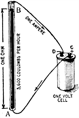
Fig. 543. If the current strength in fig. 543 be one ampere, the quantity of electricity passing any point in the circuit per hour is 1 × 60 × 60 = 3,600 coulombs.
[469] Current Measurement.--It is necessary to adopt some arbitrary standard in order to compare currents of different strengths. The term strength of a current, or current strength means the rate of flow past any point in the circuit in a given unit of time. The unit of current, called the ampere, is defined as the unvarying current which, when passed through a solution of nitrate of silver in water (15 per cent. by weight of the nitrate) deposits silver at the rate of .001118 gramme per second.
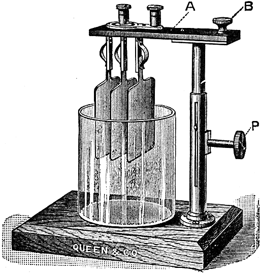
Fig. 544.--Queen weight voltameter for determining the strength of current by the weight of metal deposited in a given time. The two outside plates form the anode and are joined together and to one binding post, while the cathode is placed between them and connected to the other binding post. The cathode thus receives a deposit on both sides. An adjustable arm serves to lower the plates into the electrolyte. To calculate the strength of an unknown current which has passed through a weight voltameter, divide the gain in weight by the number of seconds the current flows through the instrument and by the weight deposited by one ampere in one second. That is, current strength in amperes = gain in weight ÷ (time in seconds × .0003286).
Ques. How much copper or zinc will one ampere deposit in one second?
Ans. .0003286 gramme of copper in a copper voltameter, or .0003386 gramme of zinc in a zinc voltameter.
[470] Ques. What is the difference between an ampere and a coulomb?
Ans. An ampere is the unit rate of flow of the current, and a coulomb is the unit quantity of electricity, that is, the ampere is the rate of current flow that will deposit .0003286 grammes of copper in one second and a coulomb is the quantity of electricity that passes a given point in one second when the current strength is one ampere. In other words a coulomb is one ampere second.
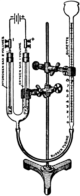
Fig. 545.--Gas voltameter for determining the strength of current by the volume of gas evolved. To use, connect up as shown in the illustration. Adjust so that the zero position of the burette is about one-half inch below the level of the top of the U tube. Pour acidulated water into the mouth of the burette till the water in the U tube is about one-half inch from the top. With the electrodes inserted through the corks, carefully place each one in position by giving a slight twist to the right as the cork enters. The water level in the U tube and burette should now be the same, or further adjustment must be made to attain this result. The level in the burette does not necessarily have to correspond with the zero graduation, but must not be below it. Unclamp the burette and hold it nearly horizontal. The liquid will not run out if the corks be tight, so that this is the air leakage test. Attach the connectors and wires from the current source (which should have a pressure of 2 or more volts) placing a switch in the circuit. When the switch is closed, bubbles of gas will rise in the U tube from both electrodes, displacing the water and forcing it up the burette. Hydrogen will be liberated over the negative electrode, and oxygen over the positive electrode in the proportion of twice as much hydrogen as oxygen. To calculate the current strength, divide the volume of gas liberated by the time in seconds, and by the volume of gas liberated (in cubic centimeters) by one ampere in one second and by .1733; that is: amperes = volume of gas liberated ÷ (time in seconds × .1733).
EXAMPLE.--If an arc lamp require a current of 8 amperes, how much electricity does it consume per hour?
Since one coulomb = one ampere second, the quantity of electricity consumed per hour is
8 amperes × ( 60 × 60 ) = 28,800 coulombs.
[471] Voltameter.--A voltameter is an electrolytic cell employed to measure an electric current by the amount of chemical decomposition the current causes in passing through the cell. There are two classes of voltameter:
Ques. What is the difference between these two classes of voltameter?
Ans. In one, the current strength is determined by the weight of metal deposited or weight of water decomposed, and in the other by the volume of gas liberated.
Ques. How should the plates of a weight voltameter be treated before use?
Ans. They must be thoroughly cleaned and polished with sandpaper, the sand being afterwards removed by placing them in running water. The fingers must not be placed on any part of the plate which is to receive the deposit.
Ques. What form of voltameter has been selected to measure the International ampere?
Ans. The silver voltameter arranged as here specified:
The cathode on which the silver is to be deposited shall take the form of a platinum bowl, not less than 10 cms. in diameter, and from 4 to 5 cms. in depth.
The anode shall be a disc or plate of pure silver some 30 sq. cms. in area, and 2 or 3 cms. in thickness. This shall be supported horizontally in the liquid near the top of the solution by a silver rod riveted through its center.
To prevent the disintegrated silver which is formed on the anode falling upon the cathode, the anode shall be wrapped around with pure filter paper, secured at the back by suitable folding.
The liquid shall consist of a neutral solution of pure silver nitrate containing about 15 parts by weight of the nitrate to 85 parts of water.
[472] Ques. What is the value of the International ampere as measured with the silver voltameter?
Ans. The International ampere is represented sufficiently well for practical use by the unvarying current which, when passed through a silver voltameter (as described above) deposits silver at the rate of .001118 gramme per second.
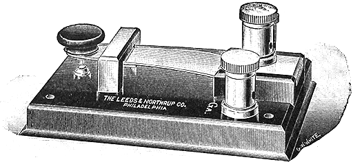
Fig. 546.--Single contact and short circuiting key. This key is intended especially for use with D'Arsonval galvanometers in zero deflection methods. The key is connected in circuit with the galvanometer so that whenever the key is not depressed, the galvanometer is short circuited, and its oscillations quickly damped out by the currents induced in its coil. The back end of the spring is held in a slot in a rubber block attached to the base.
Ohm's Law and the Ohm.--The various tests here described depend for their truth upon the definite relation existing between the electric current, its pressure, and the resistance which the circuit offers to its flow. This relation was fully investigated by Ohm in 1827. Using the same conductor, he proved not only that the current varies with the pressure, but that it varies in direct proportion.
Ohm's law has already been discussed in a previous chapter and the several ways of expressing it are repeated here for convenience:
| 1. | Amperes | = | voltsohms ; |
| [473] | |||
| 2. | Volts | = | amperes × ohms ; |
| 3. | Ohms | = | voltsamperes . |
Various values have been assigned, from time to time, to the ohm or unit of resistance, the unit in use at the present time being known as the International ohm. This was recommended at the meeting of the British Association in 1892, was adopted by the International Electrical Congress held in Chicago in 1893, and was legalized for use in the United States by act of Congress in 1894. The International ohm in graphically defined in fig. 548. The previous values given to the ohm which were more or less generally accepted are as follows:
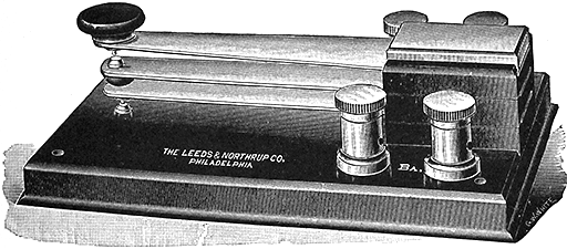
Fig. 547.--Double contact key. It is of especial value in connection with a Wheatstone bridge. When used with the latter it forms a combination battery and galvanometer key. The battery is wired to the top leaves of the key and the galvanometer to the lower leaves. Hence, when operated, the battery circuit will be closed before the galvanometer circuit, as it is desirable to avoid undue disturbance of the needle.
[474] The Siemens' Ohm.--A resistance due to a column of mercury 100 cm. long and 1 sq. mm. in cross section at 0° C.
B. A. (British Association) Ohm.--A resistance due to a column of mercury approximately 104.9 cm. long and 1 sq. mm. in cross section at 0° C.
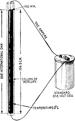
Fig. 548.--The international ohm. It is defined as the resistance of 14.452 grammes of mercury in the form of a column of uniform cross section 106.3 centimeters in length, at a temperature of 0° C. This is approximately equivalent to a column 106.3 cm. long, having a uniform cross section of 1 sq. mm. In the figure the international ohm is defined graphically. The resistance of the external circuit and the standard one volt cell is assumed to be zero.
Legal Ohm.--A resistance due to a column of mercury 106 cm. long and 1 sq. mm. in cross section at 0° C. This unit was adopted by the Paris conference of 1884.
OHM TABLEA
| Date | International Ohm | Legal Ohm | B. A. Ohm | Siemens' Ohm | |
| International Ohm | 1893-4 | 1.0000 | 1.0028 | 1.0136 | 1.0630 |
| Legal Ohm | 1884 | .9972 | 1.0000 | 1.0107 | 1.0600 |
| B. A. Ohm | 1864 | .9866 | .9894 | 1.0000 | 1.0488 |
| Siemens' Ohm | .9407 | .9434 | .9535 | 1.0000 |
[A] NOTE.--In the above table to reduce, for instance, British Association ohms to International ohms, multiply by .9866, or divide by 1.0136; to reduce legal ohms to International ohms, multiply by .9972, or divide by 1.0028, etc.
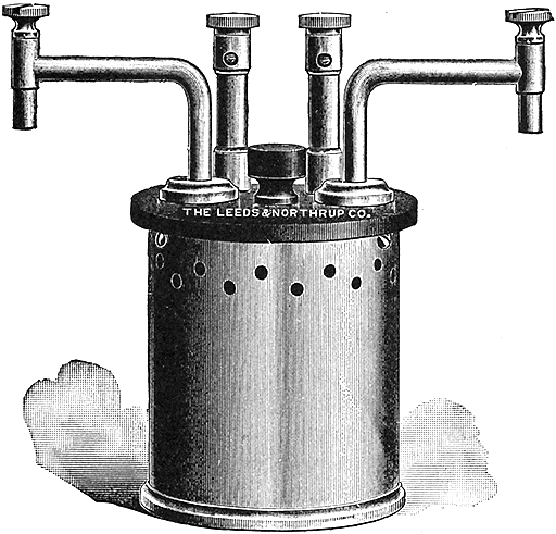
Fig. 549.--Leeds and Northrup one ohm standard resistance (Reichsanstalt form); adjusted at 20° C. Low resistance standards may be properly divided into two classes: 1. those which are designed primarily as resistance standards, and 2. those designed as current carrying standards. Those of the first mentioned class are often used to measure currents up to their capacity. The above standard has both pressure and current terminals. The binding posts for the former are mounted on high posts so as to be easily accessible when the standard is immersed in oil. When used as a resistance standard of precision, it should not be subjected to a current of more than one ampere, and when used as a current carrying standard of lesser accuracy, a current of 2 or 3 amperes may be used.
[476] Practical Standards of Resistance.--The column of mercury as shown in fig. 548, is the recognized standard for resistance, however, in practice, it is not convenient to compare resistances with such a piece of apparatus, and therefore secondary standards are made up and standardized with a great degree of precision. These secondary standards are made of wire. The material generally used being manganin or platinoid.
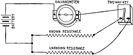
Fig. 550.--Direct deflection method of testing resistances; a useful and simple method which may be used in numerous tests. Galvanometer readings are taken through the known, and unknown resistances, and the current being proportional to the deflections, the value of the unknown resistance is easily calculated.
Resistance Measurement.--Resistance is that which offers opposition to the flow of electricity. Ohm's law shows that the strength of the current falls off in proportion as the resistance in the circuit increases. This gives a basis for measuring resistance.
There are various methods by which an unknown resistance may be measured, as by the:
Direct Deflection Method.--This method is based on the fact that the greater the current through a galvanometer the greater the deflection of the needle; it is a simple method and is capable of extended application.
The apparatus required consists of battery, galvanometer, known resistance, and double contact key. The connections are made as in fig. 550. The known resistance is put in circuit with the galvanometer and after noting the deflection, the key is moved so as to cut out the known resistance and throw into circuit the unknown resistance. The deflection of the galvanometer is again noted and compared with the first deflection.
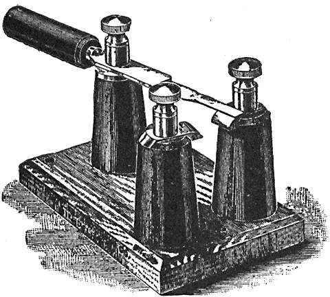
Fig. 551.--Charge and discharge key, adapted to condenser testing where the condenser is to be alternately charged and discharged. The insulated handle enables the key to be used without insulating the body.
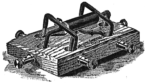
Fig. 552.--Pohl commutator. This is equivalent to a two pole double throw switch. The depressions in the base are filled with mercury into which the contacts dip in closing the circuit.
If the deflections be proportional to the current, the unknown resistance will be as many times the known resistance as the deflection with the known resistance is greater than the deflection with the unknown resistance.
[478] Method of Substitution.--This is the simplest method of measuring resistance. The resistance to be measured is inserted in series with a galvanometer and some constant source of current, and the galvanometer deflection noted. A known adjustable resistance is then substituted for the unknown and adjusted till the same deflection is again obtained. The value of the adjustable resistance thus obtained is equal to that of the resistance being tested.
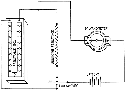
Fig. 553.--Substitution method of testing resistances. The connections and apparatus are the same as in fig. 550, except that a resistance box is used in place of the known resistance. In making the test, first note deflection with unknown resistance in circuit, then press key so that the current will pass through the resistance box, and adjust the resistance in the box so that the deflection of the galvanometer is about the same as with the unknown. Now switch from one circuit to the other, changing the resistance in the box until equal deflections are obtained. When this obtains, the resistance in the box is the same as the resistance being tested.
Ques. What kind of adjustable resistance is used in making the above test?
Ans. A resistance box.
[479] Ques. Describe a resistance box.
Ans. It consists of a box containing numerous resistance coils with their ends connected to terminals and provided with plugs so that they may be thrown into or out of circuit at will, thus varying the resistance in the circuit.
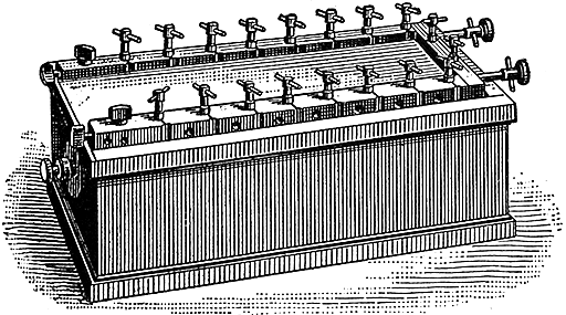
Fig. 554.--Ordinary resistance box. It contains sets of standard resistances consisting of coils of insulated wire having low conductivity and small temperature coefficient. The ends of the coils are joined to the section of the bar between the plugs. The insertion of a plug cuts out a coil. In using, care should be taken to put the plugs in with a slight twist so that there shall be no resistance introduced by poor contact.
Fall of Potential Method.--This is a very simple method of measuring resistances, and one that is convenient for practical work in electrical stations because it requires only an ammeter, voltmeter, battery and switch--apparatus to be found in every station. The connections are made as shown in fig. 555.
In making the test the ammeter and voltmeter readings are taken at the same time, and the unknown resistance calculated from Ohm's law. Accordingly, since:
solving for the resistance,
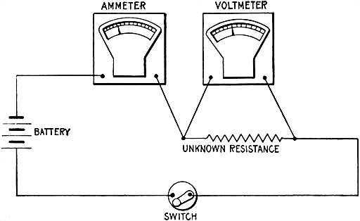
Fig. 555.--Fall of potential method of testing resistances; a convenient method for testing at stations, requiring only the usual instruments to be found at a station. The resistance of the voltmeter must be very high, otherwise the test must be made as in fig. 556.
EXAMPLE.--If in fig. 555 the readings show 6 volts and 2 amperes how many ohms is the resistance being tested?
Substituting in formula (2)
[481] Ques. Can this test be made with any kind of voltmeter?
Ans. Its resistance must be very high to avoid error. When a voltmeter having small resistance is used, it should be connected so as to measure the fall of pressure across both ammeter and unknown resistance as shown in fig. 556.
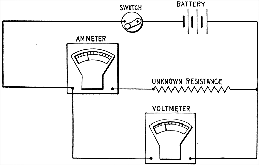
Fig. 556.--Fall of potential method of testing resistances; diagram showing connections for testing with low resistance voltmeter. The resistance measured with this connection will be the sum of the resistances of the coil and the ammeter. The resistance of the ammeter is usually known and can be subtracted from the sum to obtain the required resistance.
Differential Galvanometer Method.--This is what is known as a nil or zero method, that is, a method of making electrical measurements in which comparison is made between two quantities by reducing one to equality with the other, the absence of deflection from zero of the instrument scale showing that the equality has been obtained.
[482] The test is made with a differential galvanometer, and resistance box connected as in fig. 557. The current then will divide so that part of it flows through the resistance being tested and around one set of coils of the galvanometer while the other part will flow through the resistance box and the other set of coils as indicated. When the resistance box has been so adjusted that its resistance is the same as the unknown resistance the current in the two branches will be equal, and the needle of the galvanometer will show no deflection.
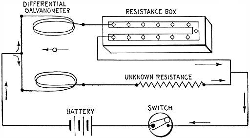
Fig. 557.--Differential galvanometer method of testing resistances. In making the test, the resistance box is adjusted till the galvanometer needle shows no deflection. When this condition obtains, the resistance in circuit in the resistance box is equal to the unknown resistance, hence, a reading of the box gives the value of the unknown resistance.
Ques. What name is given to this method of testing?
Ans. It is called a zero method, distinguishing it from deflection methods.
Ques. For what kind of resistance is the method adapted?
Ans. Since it is a nil or zero method, it is better adapted to the measurement of non-inductive than of inductive resistances.
[483] Ques. What precaution should be taken with inductive resistances?
Ans. The current must be allowed to flow until it becomes steady to overcome the influence of self-induction.
Ques. What may be said with respect to the differential galvanometer method?
Ans. With an accurate instrument it is very reliable.
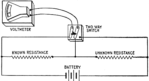
Fig. 558.--Drop method of testing resistances. The apparatus is connected as shown and readings taken with voltmeter across known and unknown resistance. The unknown resistance is then easily calculated.
Drop Method.--This is a convenient method, and one which may be used for measuring either high or low resistances with precision. It is used for many practical measurements, and requires only a voltmeter, battery, known resistance and a two way switch.
The instruments are connected as in fig. 558, and in making the test, the voltmeter is switched into circuit across the known [484] resistance and then across the unknown resistance, readings being taken in each case. The value of the unknown resistance, is then easily calculated from the following proportion:
| drop across known resistancedrop across unknown resistance | = | known resistanceunknown resistance |
from which
| unknown resistance | = | known resistance × drop across unknown resistancedrop across known resistance |
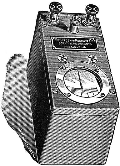
Fig. 559.--Leeds and Northrup portable galvanometer (pointer type A). The sensitiveness of this instrument is such that it may be substituted in numerous cases for the non-portable reflecting type of galvanometer; as for instance, in the checking of ammeters and voltmeters to an accuracy of .2% by the potentiometer method, and on almost all Wheatstone bridge measurements to commercial accuracies. A current of 2 micro-amperes will cause the pointer to move 1 mm. over the scale, that is, it has a sensibility of 500,000 ohms. The method of suspending the moving system is such as to practically eliminate initial friction which is of value in all zero deflecting methods. The suspensions and moving system are guarded by springs, which together with the solid construction of the case render the instrument capable of withstanding rough usage. Overall dimensions are 5-1/4" x 2-5/8" x 3-1/2"; weight about 3 pounds.
[485] Ques. What may be substituted for the voltmeter?
Ans. A high resistance galvanometer, whose deflections are proportional to the current, the value of the deflections being substituted in the formula.
Ques. What precaution should be taken in making the test?
Ans. The current used should not be strong enough to appreciably heat the resistance, and if the current be not very steady, several readings should be taken of each measurement and the average values used in the formula.
Ques. How are the most accurate results obtained?
Ans. By selecting the known resistance as near as possible to the supposed value of the unknown resistance.
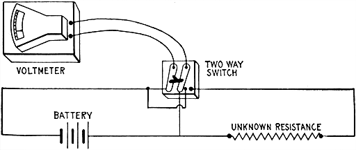
Fig. 560.--Voltmeter method of testing resistances. Knowing the resistance of the voltmeter, turn switch to the left and from reading calculate resistance corresponding to one division of the scale. Turn switch to right and multiply reading by resistance required for deflection of one division. This gives resistance of voltmeter and unknown resistance; subtracting from this the resistance of voltmeter gives value of the unknown resistance.
Voltmeter Method.--This is a direct deflection method and consists in determining first the resistance that will deflect the needle through one division of the scale on a given battery [486] current, then with this as a basis for comparison the voltmeter is connected across the unknown resistance whose value is easily calculated from the reading.
In making the test, the instruments are connected as in fig. 560. The current from battery is first passed through the galvanometer by turning switch as shown.
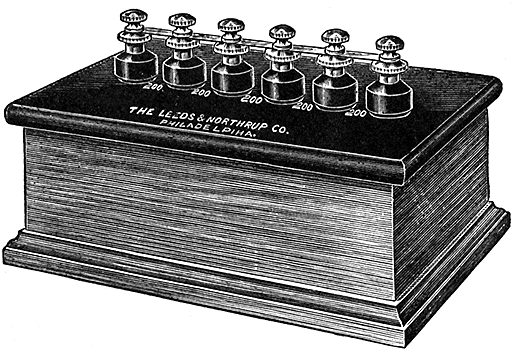
Fig. 561.--Megohm box or set of standard high resistances. The box contains five resistances of 200,000 ohms each. The six pillars are petticoat insulated, the resistances being placed between each pair of pillars. There is a double contact post on top of each pillar so that these can be connected together with copper links.
Assuming that the resistance of the instrument is 8,000 ohms and that the current deflects the needle through 10 divisions of the scale, then for a deflection of one division the resistance is
8,000 × 10 = 80,000 ohms.
Accordingly, if, when the switch is moved to the right, connecting the voltmeter across the unknown resistance, the needle be moved through 6 divisions of the scale, the combined resistance of the voltmeter and unknown resistance is
80,000 ÷ 6 = 13,333-1/3 ohms,
and subtracting the resistance of the voltmeter, the value of the unknown resistance is
13,333-1/3 - 8,000 = 5,333-1/3 ohms.
[487] Ques. For what kinds of test is the voltmeter method best adapted?
Ans. For measuring high resistances, as the insulation of wires, etc.
Ques. What may be said with respect to the current used?
Ans. Its voltage should be as high as possible within the limits of the voltmeter scale.
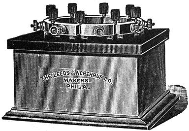
Fig. 563.--Standard resistance box: 100,000 ohms, in four units of 10,000, 20,000, 30,000, and 40,000 ohms. An "infinity" plug separates each coil from the ones adjacent. Segments are elevated from the hard rubber top by special washers in order to increase insulation. Binding posts are so arranged as not to be in the way when plugs are used.
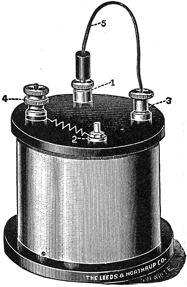
Fig. 562.--Standard high resistance box: 100,000 ohms. It is mounted in a brass box with a hard rubber top. Connections should be made to terminals marked 3 and 4. When the flexible cord is on plug 1, the box is short circuited, but when on plug 2, the resistance of 100,000 ohms is in series. The box is especially suited to rapid cable testing.
Ques. In testing cable insulation what is desirable with respect to voltmeter and current?
Ans. A low reading voltmeter should be used in connection with a large battery.
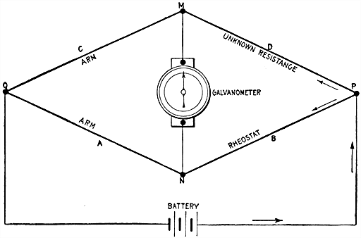
Fig. 564.--Diagram showing principle of Wheatstone's bridge. A, B, C, and D, are the four members which constitute the bridge. The current from the battery divides at P, part traversing DC, and part traversing BA. The galvanometer connected to M and N will indicate when the currents are equal in the two branches by giving no deflection. This is then a zero or nil method of testing. The resistances and keys required in testing are shown in fig. 565. In the actual instrument, the members A, B, C, and D are known by the names given in the figure.
Wheatstone Bridge Method.--For accurate measurements of resistance this method is almost universally used. The so-called "Wheatstone" bridge was invented by Christie, and improperly credited to Wheatstone, who simply applied Christie's invention to the measurement of resistances.
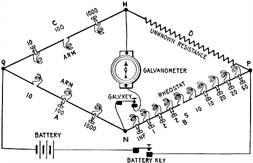
Fig. 565.--Diagram showing arms of Wheatstone bridge, resistances and method of connecting galvanometer, battery and unknown resistance.
The bridge consists of a system of conductors as shown in fig. 564. The circuit of a constant battery is made to branch at P into two parts, which re-unite at Q, so that part of the current flows through the point M, the other part through the point N. The four conductors A, B, C, D, are spoken of as the arms of the balance or bridge. It is by the proportion existing between [489] the resistances of these arms that the resistance of one of them can be calculated when the resistances of the other three are known. When the current which starts from the battery arrives at P, the pressure will have fallen to a certain value. The pressure in the upper branch falls again to M, and continues to fall to Q. The pressure of the lower branch falls to N, and again falls till it reaches the value at Q. Now if N be the same proportionate distance along the resistances between P and Q, as M is along the resistances of the upper line between P and Q, the pressure will have fallen at N to the same value as it has fallen to at M; or, in other words, if the ratio of the resistance C to the resistance D be equal to the ratio between the resistance A and the resistance B, then M and N will be at equal pressures. To find out if this condition obtain, a sensitive galvanometer is placed in a [490] branch wire between M and N which will show no deflection when M and N are at equal pressure or when the four resistances of the arms "balance" one another by being in proportion, thus:
If, then, the value of A, B, and C be known, D can be calculated. The proportion (1) is reduced to the following equation before substituting.
[491] For instance, if A and C be, as in fig. 565, 10 ohms and 100 ohms respectively, and B be 15 ohms, D will be (15 × 100) ÷ 10 = 150 ohms.
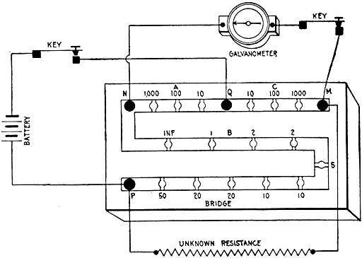
Fig. 566.--Diagram showing usual arrangement of resistances in arms of Wheatstone's bridge. In practice the bridge is seldom or never made in the lozenge shape of the diagrams, figs. 564 and 565, these being given merely for clearness. The resistance box of fig. 554 is, in itself, a complete "bridge," the appropriate connections being made by screws at various points. The letters in the above diagram correspond with those in figs. 564 and 565, and the three figures should be carefully compared.
As constructed, Wheatstone bridges are provided with some resistance coils in the arms A and C, as well as with a complete set in the arm B. The advantage of this arrangement is that by adjusting A and C, the proportionality between B and D can be determined, and can, in certain cases, be measured to fractions of an ohm. In fig. 565 resistances of 10, 100, and 1,000 ohms are included in the arms A and C.
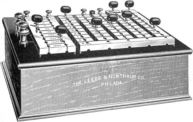
Fig. 567.--Standard resistance box and Wheatstone bridge. This pattern is a modification of the Anthony form of bridge. All the resistances are wound upon metal spools. The bridge ratio coils are 1, 10, 100, 1,000, 10,000. The rheostat coils are arranged in five rows, of ten coils each. The ordinary decade plan (explained in fig. 570) is followed. The coils may be joined in series in multiple, or in any combination of series and multiple. The coils may thus be checked against each other in many combinations. For instance, all the ten ohm coils taken in parallel may be compared with any one ohm coil. The precision of adjustment is said to be 1/20th of 1% for the coils of the tenth ohm series, and 1/50th of 1% for the coils of the rheostat. The ratio coils are certified to be like each other to within 1/100th of 1%. The box is supplied with battery and galvanometer keys of substantial construction.
Ques. Describe the method of testing with the bridge.
Ans. Fig. 567 illustrates the general arrangement of resistances to be found in an ordinary bridge. The connections are made as shown. In testing, first depress the battery key, then tap the galvanometer key. This should be repeated adjusting the resistances till no deflection is obtained. The resistance then in the arm B × (C ÷ A) will give the value of the unknown resistance.
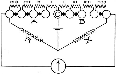
Fig. 568.--Ratio coils of Wheatstone bridge. Almost every box intended to serve as a Wheatstone bridge is furnished with a set of coils which forms the arms of proportion or ratio arms of the bridge. There is a choice of several different ways of arranging these coils. The figure shows the simplest arrangement, which is employed in boxes not intended for the highest accuracy. The required ratio, as for instance 1:100, is obtained by withdrawing a plug from each arm A and B. Ratios 1/1, 1/10, 1/100, 10/100, etc., or 1,000/1, 1,000/10, 1,000/100, 100/100, etc., are obtainable in this manner. This simple arrangement is open not only to the objection that the contact resistance of the plugs which remain in is always included with the resistance unplugged, but also to all other objections to be urged against the use of many plugs where a few will do. The method has the limitation that it is not possible to reverse the arms of the bridge, that is, to transpose the arms A and B.
Ques. Why should the battery key be depressed before the galvanometer key?
Ans. To avoid the sudden swing of the galvanometer needle, which occurs on closing circuit in consequence of self-induction.
[493] Ques. How is it known whether too much or too little resistance be unplugged?
Ans. The galvanometer needle will be deflected to one side for too much resistance, and to the opposite side for too little resistance.
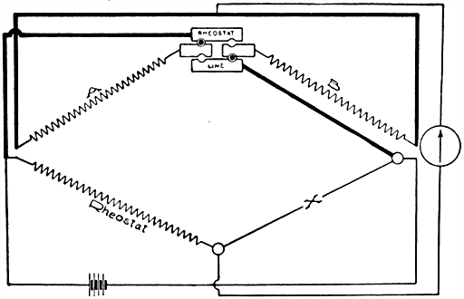
Fig. 569.--Method of reversing arms of Wheatstone bridge with reversing blocks. The arrangement shown in the figure is classical, being that used in the English post office type of Wheatstone bridge. It is open to the objections which apply to the use of several plugs, one of which is withdrawn to obtain the desired resistance.
Ques. What is the meaning of "Inf.," marked on the bridge?
Ans. It stands for "infinity," because the resistance coil at the point marked infinity is omitted so that adjacent sections of the arm are disconnected when the plug is taken out.
In fact, the air gap interposed by the removal of the plug by no means provides an infinitely great resistance, but is usually called such because it is vastly greater than any of the other resistances of the bridge.
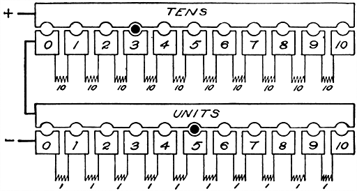
Figs. 570 and 571.--Diagrams illustrating the decade plan of combining resistance coils. In this method the coils are connected in series and the arrangement avoids the disadvantage of the ordinary Wheatstone bridge in that the latter requires a large number of plugs to short circuit the resistances not in use, which introduces an element of uncertainty as to resistance of the plug contacts and the necessity of adding up the values of all the unplugged resistances in order to determine the total resistance in circuit. The necessary regular succession of values in a rheostat built on the decade plan can be obtained with either nine or ten coils per decade. The chief reason for using the latter number is found in the facility with which all the coils of one decade can be compared with one coil of the next higher decade, thus permitting the coils of a rheostat to be checked among themselves. Thus, the ten 1 ohm coils can be checked with a 10 ohm, the ten 10's with a 100, etc. In some sets the ten coils of a decade can be connected in series or in parallel, and it then becomes an advantage to have ten coils to a decade, since the coils in one decade in parallel equal one of the coils of the next lower decade. When these latter advantages are not required, and especially when dials or sliding switches are used, there is little or no advantage in using more than nine coils per decade, as shown in fig. 570. Here all the coils of the set are connected in series so that the circuit is never open. Thus it is a slight advantage to have permanent connections a, b, and c, because all the coils of a decade can be thrown in circuit by simply pulling out a plug, it not being necessary to insert it again, as would be the case if the a, b, and c connections were not used. Moreover, if any plug make bad contact, its effect is somewhat lessened by having this bad contact shunted by the remaining coils of the decade. Again, there are occasions where violent deflections of a galvanometer are prevented by not having the circuit entirely open when a plug is taken out.
[495] The Decade Plan.--In this method of combining resistance coils, there are 9 or 10 one ohm coils for the units place, 9 or 10 ten ohm coils for the tens place, 9 or 10 one hundred ohm coils for the hundreds place and so on. Each series of coils of the same value is designated a decade. The connections are usually made as shown in figs. 570 and 571.
It is apparent from the figure that any value in any one decade can be obtained by inserting between a bar and a block, only one plug; moreover if several decades be in series, any value up to the limit of the set can be read off directly from the position of the plugs without having to add up the unplugged resistance as in the ordinary arrangement.

Fig. 572.--Two plug arrangement of ratio coils. Each of the ratio coils has one of its terminals connected to a common center which corresponds to the block marked C in the figure. The other terminal of each coil is connected to an individual block, there being one block for each coil. The bar B on one side of these blocks is joined to the rheostat and the bar A on the other side to an X post. In the ordinary use of this set of ratio coils two plugs only are used. One plug is inserted between the bar A and one of the blocks, 1, 1', 10, 10', etc., of the central row of blocks. The other plug is inserted between the bar B and any one of the other blocks of the central row. There are two ratio coils of each value. To obtain an even ratio as 1,000 to 1,000', one plug is inserted between the block 1,000 and the bar A, and the other plug between the 1,000 block and bar B, the ratio arms are reversed; that is, the 1,000 ohm coil is connected to the X post and the 1,000 ohm coil to the end of the rheostat. When uneven ratios are used, the same ratio can be obtained by four different combinations. To obtain the ratio one to ten, insert a plug between A and 1, and another between B and 10, or between A and 1', and B and 10, and get 1:10, or between A and 1, and B and 10', and get 1:10', or again, between A and 1' and B and 10', and get 1' to 10'. Other ratios are obtained in a similar manner. By using more than two plugs and connecting certain of the coils in parallel combinations, a large number of other ratios may be obtained. This arrangement offers a convenient method of measuring the sensibility of a bridge and galvanometer combination that is frequently applicable. If for instance the one ohm coil is used on either side after a balance has been obtained the one ohm may be shunted with the 1,000 ohm on the same side. This will make a variation of 1/10 of 1% and the galvanometer deflection may be noted for this variation. Similarly, the 1 ohm may be shunted with the 100 for a variation of 1%, or with the 10,000 for a variation of 1/100 of 1%. The ten ohm coil may be shunted with the 1,000 for a variation of 1% and with the 10,000 for a variation of 1/10 of 1%. In the arrangement of ratio coils, errors due to plug contacts are negligible because only two plug contacts enter the circuit, and with an even ratio, it is only the difference in the resistances of the two plug contacts that can affect the result. In measuring any of the ratio coils while in the box it is only necessary to connect to the bar C and to either the bar A or B and plug in the coils to be measured.
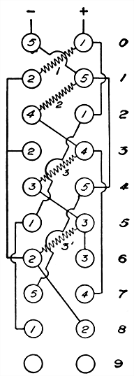
Figs. 573 and 574.--The Leeds and Northrup decade. The object of this arrangement is to reduce the number of coils required. In fig. 573, the 1, 3', 3 and 2 are connected in series. Let the terminals of the 1 ohm and 2 ohm coils be numbered (1), (2), (3), (4) and (5) (fig. 573). The current enters at point (1) and leaves the coils at the point (5), traversing 1, 3', 3, 2 = 9 ohms in all. If this series be multiplied by any factor n, then n (1 + 3' + 3 + 2) = n 9 ohms. It will be seen that if the points (1) and (5) be connected, all the coils are short circuited, and the current will traverse zero resistance. If the points (2) and (5) be connected, the 3', 3 and 2 ohm coils will be short circuited and the current will traverse 1 ohm. By extending the process so as to connect two and only two points at a time it is possible to obtain the regular succession of values n (0, 1, 2, 3, 4, 5, 6, 7, 8, 9), the last being obtained when no points are connected. Fig. 574 shows Leeds and Northrup's method of connecting these points two at a time with the use of a single plug. The circles in the diagram represent two rows of ten brass blocks each. To the first two blocks at the top of the rows, the points (5) and (1), fig. 573, are connected; to the second two, the points (2) and (5) are connected, etc., no points being connected to the last pair of blocks. Hence, if a plug be inserted between blocks 1 and 5, fig. 575, the points (1) and (5) of diagram fig. 573 are connected, giving the value of 0, if between the blocks 2 and 5 the points (2) and (5) are connected, giving the value 1, and so on. The value 9 is obtainable when the plug is in the last pair of blocks, which have no connections. Fig. 572 shows a top view of the blocks of a simple decade constructed upon this plan.
[497] Ques. What other advantages are gained with the decade arrangement?
Ans. The single plug used with each decade is never out of use, being either in the zero position or set on some value, and is therefore not easily lost by being laid aside. The use of only one plug in a decade makes it easy to ascertain that the plug is making good contact as only one block in a row is plugged at a time, the other blocks are not kept under a strain by having plugs forced tightly between them.
This strain on the blocks, which always exists in those sets in which a resistance is thrown in by removing a plug, tends to separate or loosen them and often to warp the hard rubber upon which they are mounted. Another advantage of the decade plan is that it permits obtaining a succession of values by means of sliding contacts or dial switches, a method which is becoming deservedly more appreciated.
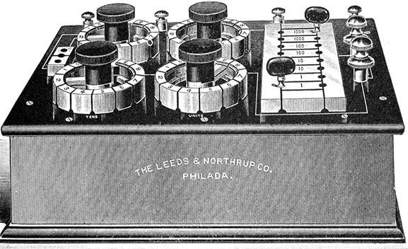
Fig. 575.--Leeds and Northrup dial Wheatstone bridge. Rotating switches are used instead of plugs, which permits quicker adjustment of the resistances, adapting it to rapid working. The ratio coils are arranged as in fig. 568. There are four dials which form the rheostat. The units dial contains 9 one ohm coils; the tens dial, 9 ten ohm coils; the hundreds dial, 9 one hundred ohm coils, and the thousands dial 9 one thousand ohm coils. The values of the ratio coils are 1, 1, 10, 10, 100, 100, 1,000, 1,000, 10,000, 10,000.
[498] Ques. What is the difference between "plug out" and "plug in" types of resistance box?
Ans. In the plug out type, resistance is put in the circuit by removing plugs, as in fig. 565; in the plug in type, resistance is put in the circuit by inserting plugs as in figs. 570 and 571.
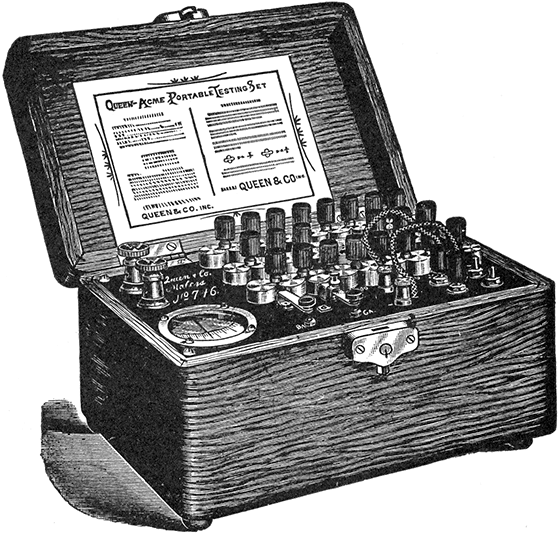
Fig. 576.--Queen Acme portable testing set. It consists of a Wheatstone bridge, with reversible arms, battery of four dry cells, D'Arsonval galvanometer, battery and galvanometer keys. There are sixteen resistance coils, having a combined resistance of 11,110 ohms. Each bridge arm is provided with three coils of 1, 10, 100 ohms, and 10, 100, 1,000 ohms respectively. The commutator admits of a ratio of 1 to 1,000 on either bridge arm, giving the set a theoretical range from .001 of an ohm to 11,110,000 ohms. For resistances above 1,000,000 ohms, the normal battery power must be increased. The contact keys are located as shown. The battery key has single contact, but the galvanometer key has double contact; depressing it closes the galvanometer circuit, and releasing it short circuits the galvanometer, bringing the latter quickly to rest.
[499] Testing Sets.--For convenience in testing, a combination of the instruments used is put up in a neat and substantial case, and known as a testing set. There are innumerable forms of testing set, a few of which are shown in the accompanying illustrations. The usual combination is a Wheatstone bridge, galvanometer, battery and necessary keys and connections.
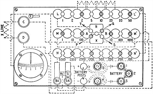
Fig. 577.--Connections and circuits of Queen acme portable testing set. There are three rows of blocks, LL', MM', NN'. LL is connected to NN' by means of a heavy copper bar, joining L' and N'. LL' and NN' constitute the rheostat, from which any resistance from 1 ohm to 11,110 ohms may be obtained by removing the proper plugs. The block N of the rheostat is connected to the lower line post D. The upper line post C is connected to the block X of the commutator. The block C has no other permanent connection, except key G. The block R of the commutator is connected to the block L of the rheostat, and has no other connection, excepting by plugs. Each half of MM' constitutes a bridge arm, designated A and B respectively. Beginning at the lower line post D, the connections form a continuous circuit through the rheostat, thence through the bridge arm B, thence through the bridge arm A, thence to the upper line post C. The commutator serves merely to reverse the bridge arms A and B. The battery terminals are connected as shown: the positive terminal directly to the common junction of the two bridge arms, and the negative terminal through the battery key to the rheostat. The positive terminal of the galvanometer is connected through the galvanometer key with the block X, and the negative terminal with the block R of the commutator or what is equivalent, with the block L of the rheostat. The commutator blocks A, B, R and X, are connected by plugs as shown. When the commutator plugs are in the position PQ, the bridge arm B is connected to the rheostat and the bridge arm A is connected to the line, the ratio between the bridge arms ratio being A ÷ B = X ÷ R but when the plugs are in the position ST, the bridge arms are reversed in position A, being connected with the rheostat and B, with the line, and the bridge arm ratio becomes A ÷ B = R ÷ X. The connections of the testing set may be more readily understood from the simplified diagram fig. 578.
Ques. Describe the operation of the Queen Acme testing set figs. 576 and 577, in measuring resistance.
Ans. Connect the terminals of the resistance to be measured to the line posts C and D. Place the battery connections on the two upper tips 0 and 1, thus throwing one end of the battery into circuit, which is sufficient until an approximate balance is obtained. Employ the 100 ohm coil in each bridge arm, and place the commutator plugs in the position PQ, or in the position ST. Then remove plugs from the rheostat until the value of total resistance employed, or nearly as may be guessed is equal to that of the unknown resistance. Now press the battery key Ba, and holding it down momentarily, press the galvanometer key Ga. If the galvanometer needle swing to the right toward the symbol + the resistance employed in the rheostat is too high and must be reduced. If the needle swing to the left toward -, the resistance employed is too low and must be increased. By altering the resistance of the rheostat accordingly, [501] a value will soon be found, which when varied slightly either way, will reverse the deflection of the galvanometer needle. Now remove the battery connection from tip 1, and place it on the tip 4, thus throwing the whole battery into circuit. Then press the keys again as before, first the battery key, then the galvanometer key. This will increase the deflection of the galvanometer needle for the same variation in the rheostat, thus [502] enabling the making of a more accurate adjustment. The measurement thus made will be the best result that can be obtained with bridge arms of equal value, but by selecting more suitable values of the two arms from the following table of bridge ratios a much higher degree of accuracy may be obtained.
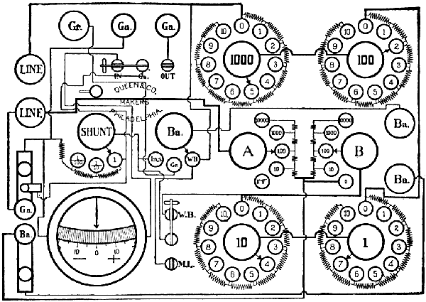
Fig. 579.--Diagram of the Queen dial decade portable testing set. Its dimensions are 9-1/2" long, 7" wide and 7" deep, and weighs 11-1/2 pounds. The resistances are arranged upon the dial decade plan, being placed in circuit by means of a rotating switch contact. The switches are so constructed that they may be turned in either direction, thereby permitting them to be turned quickly from the highest resistance in any dial to the lowest resistance in the same dial. This arrangement avoids the necessity of turning back through all the remaining resistances in any particular group of coils and is of value in locating swinging crosses or conditions of momentary balances. The connections for the various tests are made by the manipulation of one small knife switch (W.B.--M.L.) and the switch BA.; these are plainly lettered, thus avoiding the necessity of referring to a diagram of connections. In construction, the dial switches are made up of eight laminations of No. 28 B. & S. phosphor bronze, and the form is such as to prevent wearing grooves on the top of the contact studs. In this instrument the electrical circuits are soldered throughout excepting the switch contact whose resistance is negligible. The resistances are wound with manganin. The battery comprises six cells sub-divided which are easily replaceable. The galvanometer is the same as in the Queen acme set, but has the addition of an Ayrton shunt, which is useful in making insulation measurements. The necessary keys, binding posts, and switches are provided so as to facilitate the use of the instrument for the various measurements that can be made with it.
Table Showing the Best Values of Bridge Arms for Measuring any Desired Resistance
| Value of Resistance being measured | Best values of | Position of Commutator Plugs as shown in fig. 582 |
|
| A = | B = | ||
| Below 1.5 ohms | 1 | 1,000 | PQ |
| Between 1.5 and 11 ohms | 1 | 100 | PQ |
| " 11 and 78 ohms | 10 | 100 | PQ |
| " 78 and 1,100 ohms | 100 | 1,000 | PQ |
| " 1,100 and 6,100 ohms | 100 | 100 | PQ or ST |
| " 6,100 and 110,000 ohms | 1,000 | 100 | ST |
| " 110,000 and 1,110,000 ohms | 1,000 | 10 | ST |
| " 1,110,000 and 11,110,000 ohms | 1,000 | 1 | ST |
Ques. In testing with the Queen Acme set how should the plugs be placed in the commutator?
Ans. Always make the arm A the smaller except when the two arms are of equal value.
Ques. If the resistance being measured is higher than 6,100 ohms, or lower than 1,100 ohms, how should the commutator plugs be placed?
Ans. If higher than 6,100 ohms, they should be placed in the position ST; if lower than 1,100 ohms, in position PQ.
[503] When the plugs are placed in the ST position, the unknown resistance is found by dividing the value of the larger bridge arm by that of the smaller, and multiplying the total employed resistance in the rheostat by the quotient. When the plugs are placed in the PQ position, the employed resistance in the rheostat is divided by the quotient.
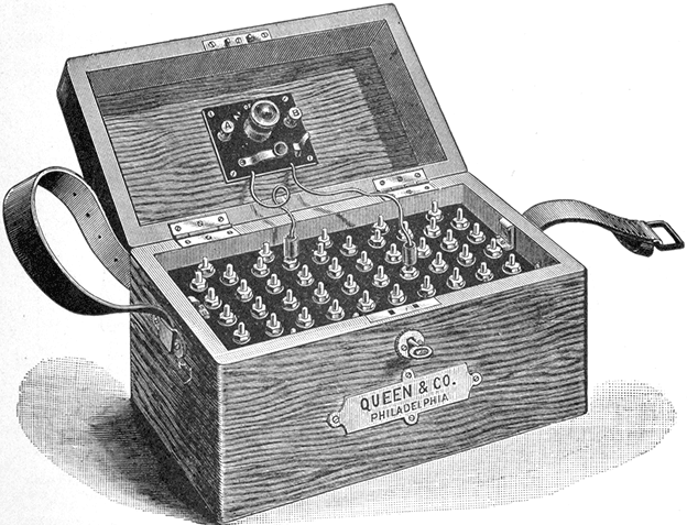
Fig. 580.--Queen portable silver chloride testing battery. The silver chloride cell has the advantage of long life, light weight, and compactness. The pressure of each cell when new is .8 volt.
Direct Deflection Method with Queen Acme Set.--To measure for instance, insulation resistance by direct deflection connect a known high resistance, say 100,000 ohms between the line post C (fig. 577), and the positive battery post. Remove all plugs from the commutator, and place all plugs in the rheostat, as any employed resistance in the rheostat will be in circuit [504] with the galvanometer and the battery. Place the battery connection so as to throw only one cell into circuit. Now press the keys and obtain a deflection of the galvanometer needle. For example: assume that the needle to be deflected about 8 divisions of the scale. Since this deflection is due to the current from one cell passing through a resistance of 100,000 ohms, then 100,000 × 8 = .8 megohms represents the resistance through which one cell will produce a deflection of one division on the scale. Hence, .8 megohms is the constant of the galvanometer.
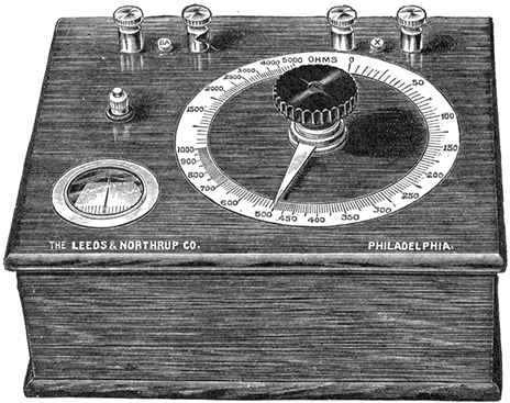
Fig. 581.--Ohmmeter. It consists essentially of a slide wire Wheatstone bridge, with the scale divided to read either directly in ohms, or in per cent. of a fixed resistance value. A galvanometer is mounted on the containing case of each, and battery and galvanometer keys are provided. In the direct reading type, the scale is so cut that when the galvanometer is balanced, the pointer of the instrument indicates the value of the resistance between the X posts. The scale is calibrated for any desired range. These ohmmeters being slide wire bridges, the greatest accuracy is at the center of the scale, hence one should be selected that will bring the part of the scale likely to be the most used at or near the center. A convenient type is that in which the scale is cut in per cent., 100 per cent. being at the center of the scale. Fixed coils of 1, 10, 100, 1,000 and 10,000 ohms are contained in the instrument with a plugging arrangement allowing any one to be used. When a balance is obtained, the actual resistance is determined by multiplying the dial reading by the value of the fixed coil in use. This amounts simply to shifting the decimal point. For instance, if the 100 ohm coil were being used, and the pointer were at .875, the resistance would be 87.5 ohms.
[505] Now, replace the known high resistance (100,000 ohms) by the unknown resistance (for instance such as a cable) the value of which is to be determined. Add enough cells to produce as large a deflection of the needle as possible. Assume that 75 cells give a deflection of 1.5 scale division. Then, the galvanometer constant multiplied by the number of cells and the product divided by the deflection will give the insulation resistance of the cable; or
as the resistance of the cable.
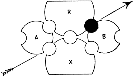
Fig. 582.--Commutator plug setting for comparing electromotive forces by the fall of potential method with Queen acme set.
Fall of Potential Method with Queen Acme Set.--To compare electromotive forces by this method, place the battery connection (fig. 577), so as to throw into circuit all the cells, taking care not to reverse them by crossing the battery cords. Plug the commutator as shown in fig. 582, and remove 1,000 ohms from bridge arm B. Place all plugs in arm A. From the rheostat unplug 5,000 ohms. Then connect one of the cells being tested, with its positive terminal to the + battery post and its negative terminal to the line post C.
[506] When the keys are pressed, the galvanometer needle will swing either to the right or to the left. If it swing toward +, reduce the resistance in the rheostat; if it swing toward -, add resistance to the rheostat. When a value is found wherein a variation of an ohm either way reverses the deflection, add to this value the resistance unplugged in arm B, and divide the sum by the resistance in arm B. The result gives the ratio between the voltages of the testing set battery and cell being tested respectively. The division is decimal and may be readily accomplished by merely pointing off as many places as there are ciphers in the resistance employed from arm B. This operation repeated with any number of different cells, will give their voltages in terms of the voltage of the testing set battery, and from these ratios their relative values may be readily obtained.
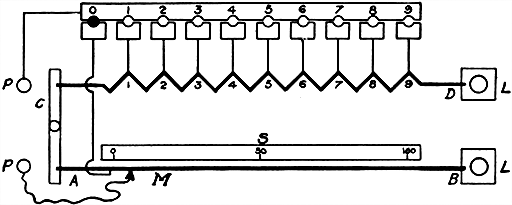
Fig. 583.--Diagram of apparatus for measuring low resistances based on the principle of the Kelvin double bridge. In the diagram AB represents a heavy piece of resistance metal of uniform cross section and uniform resistance per unit of length; CD is another piece of resistance metal of smaller cross section, and the two are joined together by a heavy copper bar, AC, into which both are silver soldered; LL are the current terminals and PP are the pressure terminals. The resistance of AB between the marks 0 and 100 on the scale S is .001 ohm. From the point 1 on the resistance CD to 0 on AB is also .001 ohm, from 2 to 0 is .002 and so on, and from 9 to 100 is .01 ohm. The slider M moves along the resistance AB and its position is read on the scale S which is divided into 100 equal parts and can be read by a vernier to thousandths. Subdivided in this way the resistance between the tap off points PP may have any value from .001 to .01 ohms by steps of .000001 ohm.
[507] If the testing set battery be replaced by a standard cell, the first measurement gives at once the voltage of the cell tested.
If the voltage of the cell or battery being tested exceed that of the testing set battery, reverse the position of the two batteries, and the subsequent operations, as outlined above, will give the desired results.
How to check a Voltmeter with the Queen Acme Set.--In using a set as in fig. 576, first remove about 10,000 ohms from the rheostat, plug the commutator as shown in fig. 582, remove 100 ohms from the arm B, of the bridge, and connect a standard cell with the positive terminal to the + battery post and the negative terminal to the line post C. Then, connect the circuit to the battery posts of the testing set the positive lead to the + post and the negative lead to the - post. Now, press both keys and note the direction of the deflection of the galvanometer needle. If it move toward +, the rheostat resistance is too high; if toward -, too low.
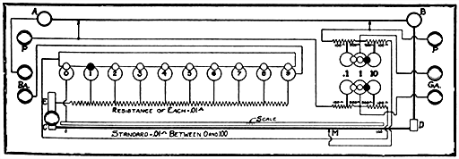
Fig. 584.--Kelvin bridge. This includes a low resistance standard of .1 ohm variable by steps of .00001 ohm, a set of ratio coils, and a holder for rods or wires to be measured, with a scale to measure their length. It is also provided with heavy flexibles to be used in measuring the resistances of irregularly shaped pieces. The connections are clearly shown in the diagram. The range of measurements of this bridge is: 1 ohm to .1 ohm by steps of .001 ohm readily estimated to .0001; .1 to .01 ohm by steps of .0001 ohm readily estimated to .00001; .01 ohm to .001 ohm by steps of .00001 ohm, readily estimated to .000001; .001 ohm down by steps of .00001 ohm, readily estimated to .000001 ohm.
[508] Change the rheostat resistance accordingly until the balance attained is such that a very slight variation of the rheostat resistance one way or the other will reverse the galvanometer deflection. To find the pressure on the circuit, add 100 to rheostat resistance and point off two places. Multiply this value by the voltage and the product will be the desired voltage.
If the voltage of the standard cell be exactly one volt, the total employed resistance represents the voltage on the circuit.
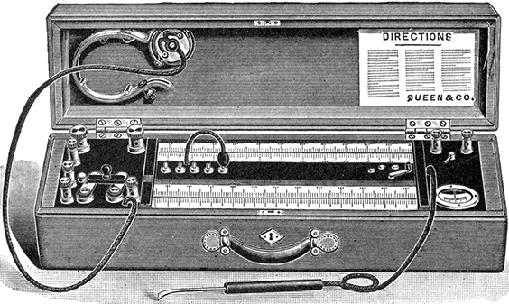
Fig. 585.--Queen slide wire bridge. It consists of a portable slide wire, Wheatstone bridge arranged to read directly in ohms in addition to its use for locating crosses and grounds. It is complete with battery, galvanometer and telephone receiver. The bridge is balanced by moving the hand stylus until the galvanometer shows no deflection or until there is no sound in the telephone receiver. In order to provide a wide range of measurement and maximum accuracy, ratio coils or multipliers having values of 1, 10, 100, 1,000 and 10,000 are provided. The scale of the instrument is arranged in two parts, one of which indicates ohms and the other is divided into uniform divisions for use when locating crosses and grounds by the Murray and Varley loop methods. A small induction coil is included so as to furnish an alternating current when using the telephone receiver.
For instance, in making a measurement on a 110 volt circuit, assume that the employing of 7,840 ohms rheostat resistance produces balance, and that increasing or decreasing this resistance by two ohms, reverses the galvanometer deflection. This indication that the setting 7,840 is uncertain, about 1/40 of 1 per cent. Since the rheostat coils are adjusted to an accuracy of only 1/5 of 1 per cent., that will be about the accuracy of the measurement.
[509] If the pressure of the standard cell be 1.018 volts, then 7,840 + 100 = 7,940. Pointing off two places, gives 79.40, which multiplied by 1.018 gives 80.82 for the voltage on the circuit.
To Measure Internal Resistance of Cell with Queen Acme Set.--First compare its voltage on open circuit with the pressure of the testing set battery. Then, shunt the cell with a known resistance, about 100 ohms, and again measure its terminal voltage. The difference between the two values thus obtained, divided by the value of the shunt resistance, will give the value of the current. To find the internal resistance, multiply the value of the shunt resistance by the ratio between the first and second measured values.
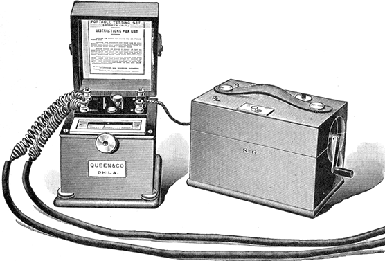
Fig. 586.--Evershed portable ohmmeter set. This testing set consists of a direct reading ohmmeter which indicates by direct reading the value of the resistance being tested, also a portable hand dynamo which provides at any required pressure the current necessary to make the test. It is adapted to the needs of supply stations, wiring contractors and dynamo builders. It is also useful in testing the insulation of underground and aerial cables, and is designed so that it can be used by ordinary workmen who are not experienced in handling delicate instruments and who, by its use, are able to obtain accurate results. The dynamo is wound for 100, 200, 500, or 1,000 volts, and is fitted with spring drum inside the case on which is coiled a twin flexible cord provided with a connector adapted for clamping under the ohmmeter terminals.
[510] For instance, assume that the open circuit voltage of the cell being tested as compared with the voltage of the testing set battery is .212 of the latter, and that when it is shunted with a resistance of 1,000 ohms, its terminal voltage is .179. Then, the total resistance is to the 1,000 ohms shunt resistance as .212 is to .179 or (.212/.179) × 1,000 = 1,184, from which deducting the 1,000 ohms shunt resistance, gives 184 ohms as the internal resistance of the cell.
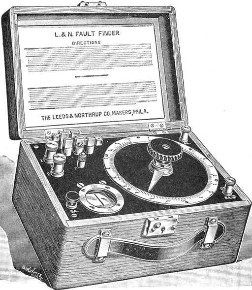
Fig. 587.--Leeds and Northrup fault finder. A lineman's instrument for the location of faults, crosses, grounds, and opens in telephone and telegraph circuits, and for the measurement of conductor and insulation resistance.
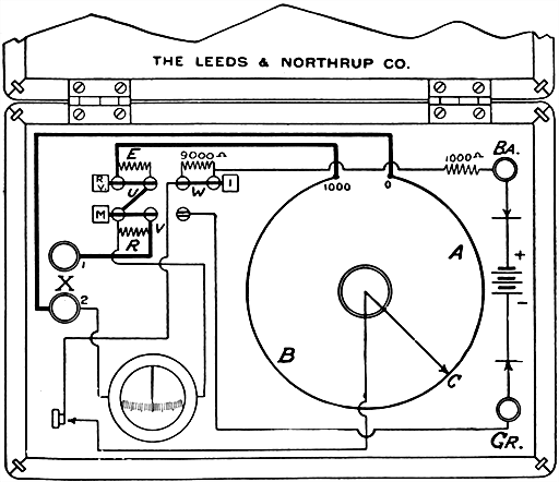
Fig. 588.--Diagram showing arrangement and connections of Leeds and Northrup fault finder. It is used to measure conductor resistance, fault resistance, to locate faults by four different tests, and when used with a buzzer and telephone, to locate opens. The essential feature of the instrument is the uniform resistance AB, which lies in a circle and which has a value of about 100 ohms. By a special construction, it is so arranged that the contact can be made at any point along it, and it is therefore equivalent to a very high resistance slide wire. It has a moving contact C and a uniform scale of 1,000 divisions. In series with this, there are the two resistances E and R which may be short circuited by the switches U and V. E has exactly the same resistance as the wire AB. R has a resistance of 100 ohms, and is the fixed resistance of the bridge arrangement for resistance measurements. The resistances of 1,000 ohms and 9,000 ohms connected to the battery post are to protect the battery and the apparatus from excessive current. The 9,000 ohms may be short circuited by the switch W.
Ammeter Test with Queen Acme Set.--Connect a low resistance in series with the ammeter and run leads from it to the testing set, the positive lead to the + battery post and the negative lead to the line post C (fig. 577). Insert a standard cell [511] between the battery posts, with positive terminal to + battery post, and negative terminal to - battery post. Plug commutator as shown in fig. 582. Remove 10,000 ohms from rheostat, and 100 ohms from bridge arm B. Determine a balance in the usual way by changing the value of the resistance in the [512] rheostat. This operation will balance the difference of pressure at the terminals of the shunt resistance against the standard cell, and its value is equal to
To determine the current flowing, divide the value of the difference of pressure thus obtained by the value of the shunt resistance.
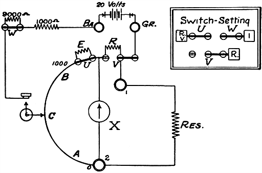
Fig. 589.--Resistance measurement with Leeds and Northrup fault finder. The diagram shows the proper connections and switch settings for measuring conductor resistance. As in the ordinary slide wire bridge, the resistance X between the two posts 1 and 2 is obtained from the formula X = A ÷ (1,000 - A) × R. To avoid the necessity of solving in each case the fraction A ÷ (1,000 - A), a table is furnished with the instrument, giving the value of this fraction for each value of A. The resistance is accordingly determined in each case by simply setting the contact C for a balance and reading from the table the resistance opposite the number corresponding to the scale reading and multiplying by 100, the value of R. To use an outside battery, remove the inside battery and connect the outside battery between the posts Gr and Ba. The pressure of this battery should not exceed 110 volts. If it exceed 25 volts, open switch W.
EXAMPLE--With an unknown resistance connected between the posts 1 and 2, the galvanometer showed a balance for a dial reading of 387. The number opposite 387 in the table is .6313; hence, X = .6313 × 100 = 63.13 ohms.
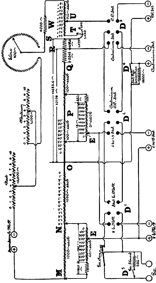
Fig. 590.--Diagram of the Queen standard potentiometer. The circuit arrangement is a method of sub-dividing the main potentiometer wire, MNOPQ, so as to provide for very accurate reading. The secondary voltage, or that used to supply current to the main potentiometer circuit, is adjusted by regulating rheostats, "Fast," "Medium," and "Slow" so that the current flow is exactly .0001 ampere. It is noted that this instrument requires a very small current for its operation. The instrument is direct reading for voltage measurements, not exceeding 1.4+. In order to determine if the current flow through the potentiometer be exactly .0001 ampere, the terminals of the standard cell binding posts are connected in circuit so that the drop over points between which they are connected are exactly equal to the voltage of the standard cell used. Binding posts are provided for connection with various standard cells. The unknown voltage to be measured is placed in opposition to the current flow in the potentiometer circuit by connecting to the binding post "XEMF." Observe that polarity is connected as required. The galvanometer with its shunt is placed in the standard cell circuit, or X circuit, by means of a double pole, double throw switch. The switch at T provides for standard cells of different values and the setting at U allows for temperature correction. The range of the instrument in volts can be increased by means of multipliers or volt boxes.
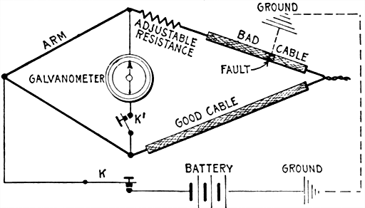
Figs. 591 to 594.--Diagrams illustrating loop testing. To properly understand the Murray or Varley loop tests, consider a Wheatstone bridge (fig. 591) the arms of which are equal. In loop testing, the rheostat is replaced by a length of cable and the unknown resistance also by a length of cable, as in fig. 592, both being similar in resistance per foot. If both lengths be the same, their resistances are the same and the bridge balances. Now shorten one cable and add resistance in series with it until the bridge again balances as in fig. 593. The added resistance equals that of the piece cut off. Hence, if the resistance per foot be known, the length of the shorter piece can be easily calculated. In the Murray and Varley tests, the battery circuit is by ground connections instead of by wire. In the Murray loop the arrangement is similar to fig. 592, the battery circuit being completed by ground connection through fault in defective cable. Fig. 594 shows the general arrangement of the Varley loop.
[515] Loop Test.--This is a method of locating a fault in a telegraph or telephone circuit when there is a good wire running parallel with the defective one. In the process, the good and bad wires are joined at their distant ends and one terminal of the battery is connected to a Wheatstone bridge, while the other terminal is grounded. There are different ways of making loop tests as by:
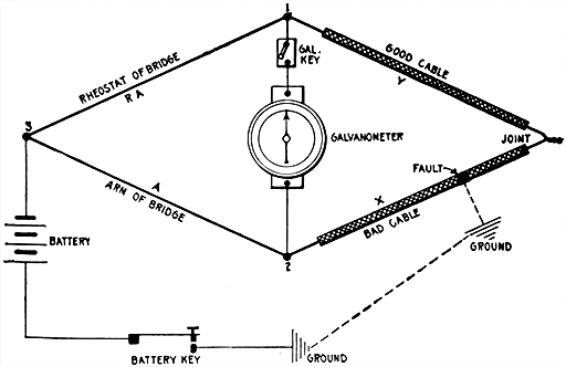
Fig. 595.--The Murray loop test. The apparatus is connected as in the figure. The rheostat of the bridge is used in place of the second arm to permit large adjustment. X and Y are the resistances of the cable between the fault and the points 1 and 2 respectively.
The Murray Loop.--In this test only one of the two regular bridge arms is used, the other being replaced by the rheostat giving an arm of large adjustment.
[516] The connections are shown in fig. 595. In making the test, close key and note the deflection of the needle due to pressure of chemical action at fault, if any. This is called the false zero.
Now apply the positive or negative pole of the battery by depressing the battery key, and balance to the false zero previously obtained by varying the resistance in arms A or B. Then by Wheatstone bridge formula: RX=AY, and L=X+Y; Y=L-X, whence
X = A/(R+A)
Y = L( R/(B+A) )
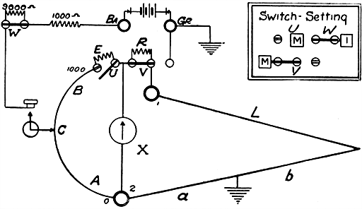
Fig. 596.--Murray loop method of fault location with Leeds and Northrup fault finder. Case I where there are two wires having equal resistance, in one of which there is a fault. Connect and set switches as shown; join the good wire to post 1 and the faulty wire to post 2. The resistance of E is equal to that of AB. From the symmetry of the arrangement, it is evident that, if the fault were exactly at the junction between the good and bad wires, the contact point C would rest for a balance at 1,000 on the scale, or at 500 if the fault were half-way along the bad wire; hence, at whatever point it comes to rest, the reading divided by 1,000 and multiplied by the length of the bad wire is the distance from the instrument to the fault.
EXAMPLE--In a pair of equal wires, 5.8 miles long, one is grounded. With the connections made as above, and the galvanometer balanced for the dial reading 124, the distance to the fault is (124 × 58) ÷ 1,000 = .7192 miles.
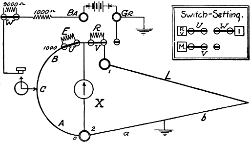
Fig. 597.--Murray loop method of fault location with Leeds and Northrup fault finder: Case II, where the good and bad wires are unequal. The figure shows the connections. It is the ordinary Murray loop and it is evident that the resistance a, to the fault will be obtained from the formula a = (A ÷ 1,000) × r, where r is the resistance of the loop, and A is the reading of the contact C on its scale. The distance d, to the fault is obtained from the formula d = Ar ÷ (1,000 × M), where M is the resistance per mile of the faulty wire.
EXAMPLE--A wire having a resistance M of 16.46 ohms per mile is grounded. This wire was looped with a wire of unknown resistance and the total resistance of the loop r was measured and found to be 54.07 ohms. Connections were made as in the figure, and the reading A was found to be 332. Substituting these values in the above formula: d = (332 × 54.07) ÷ (1,000 × 16.46) = 1.09 miles.
Ques. How may the distance from 2 to the fault be determined in knots or miles.
Ans. Divide Y by resistance per knot or mile.
[517] The Varley Loop.--This is a method of locating a cross or ground in a telephone or telegraph line or other cable by using a Wheatstone bridge in a loop formed of a good wire and the faulty wire joined at their distance ends. One terminal of the battery is grounded and the other connected to a point on the bridge at the junction of the ratio arms. The rheostat arm then includes the resistance of the rheostat plus the resistance of the fault, while the unknown arm includes the resistance of the good wire plus the resistance of the bad wire beyond the fault. When the bridge is balanced, the unknown resistances may be readily determined by a simple equation.
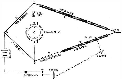
Fig. 598.--The Varley loop test. The diagram shows the various connections. X and Y are the resistances of the cable between the fault and the points 1 and 2 respectively. L is the resistance of the good and bad cable or X + Y.
[518] In making the Varley loop test, the resistance of looped cable or conductors is measured, and then connected as in fig. 598. Close the battery key and adjust R for balance.
When earth current is present, the best results are obtained when the fault is cleared by the negative pole, and just before it begins to polarize. If X be the resistance from 2 to the fault, then
X = (L - R) / 2
also, X divided by the resistance of the cable or conductor per knot or mile gives the distance of fault in knot or miles.
When the resistance of the good wire used to form a loop with the defective wire, together with that portion of the defective wire from the joint to the fault is less than the resistance of the defective wire from the testing station to the fault, the resistance R must be inserted between point 1 and the good conductor, the defective wire being connected directly to point. The formula in this case is
X = (L + R) / 2
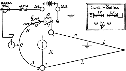
Figs. 599 and 600.--Varley loop method of fault location with Leeds and Northrup fault finder. This method may be used as a check on the Murray methods. Connect the faulty wire to 1, and measure the resistance of the loop. Then throw switches as shown in the fig. 600. Let: a = resistance to fault, d = distance to the fault in miles, M = resistance of the faulty wire per mile, r = resistance of the loop, R = resistance of the coil R, or 100 ohms, T = A ÷ (1,000 - A) to be read from the table. From the Wheatstone bridge relation: a = (r - 100T) ÷ (T + 1), and d = (r - 100T) ÷ (T + 1)M.
EXAMPLE--A wire having a resistance of 16.46 ohms per mile is grounded. This was looped with a wire of unknown resistance and the resistance of the loop was found to be 54.07 ohms. Connections were made as in the figure, and the reading A was found to be 234. From the table T = .3055, and substituting: d = (54.07 - 30.55) ÷ (1.3055 × 16.46) = 1.094 + miles.
[519] Special Loop.--This method may be used to advantage where the length of the cable or faulty wire only is known and where there are two other wires which may be used to complete the loop. It is not necessary that the resistance of the faulty wire and the length and resistance of the other wires be known. Figs. 601 to 604 show the connections and method of testing.
EXAMPLE.--All the wires in a cable 10,852 ft. long were found to be grounded so that none of them could be used as good wires. Two wires were selected out of another cable going to the same place by a different route and securely joined to one of the grounded wires at the distant end. This grounded wire and one of the good ones were connected as shown in figs. 601 and 602 and the reading A was found to be 307. [520] Connections were then made as shown in figs. 603 and 604 and A was found to be 610. What is the value of d?
According to formula
d = AL/A = (307 × 10,853)/610 = 5,461 ft.
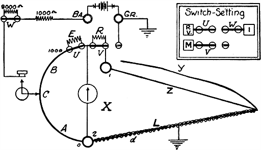
Figs. 601 and 602.--Special loop test with Leeds and Northrup fault finder. For the first measurement connect the faulty wire to 2, either of the good wires, as Z, to 1, the post Gr to ground, and short circuit the coils R and E by closing switches U and V as in the figures. Balance in the usual way and call the dial reading A. For the second measurement, connect the post Gr. (disconnected from ground), to the other good wire y as shown in figs. 603 and 604, and get another balance; call this reading A'. The distance d, to the fault is determined from the simple formula d = AL ÷ A' where L is the length of the cable or faulty wire.
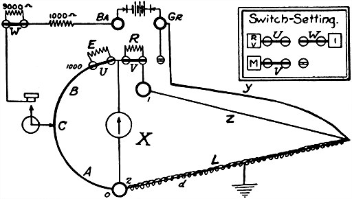
Figs. 603 and 604.--Special loop test as made with the Leeds and Northrup fault finder. Diagram showing connections for the second measurement. The special loop test may be used to advantage where the length of the cable or faulty wire only is known, and where there are two other wires which may be used to complete the loop. To use an outside battery, connect one pole to Ba, and ground the other. The pressure of this battery must never exceed 110 volts; if it be over 25 volts, see that switch W is open.
The Potentiometer.--For the rapid and accurate measurement of voltage, current, and resistance, the potentiometer can be recommended. Those in charge of electric light and power companies, and also those who purchase large amounts of electrical energy are realizing, more and more, the necessity of having satisfactory primary standards with which to check their volt-, ampere-, and watt-meters.
[521] When it is realized that an error of one per cent. in a commercial instrument means an error of one dollar one way or the other in every one hundred dollars charged, the need of such standardization apparatus becomes at once apparent.
The potentiometer, it should be noted, relies for its accuracy, only upon the constancy and accuracy of resistances and upon standard cells.
With the materials now available, and the skill which has been acquired in their manufacture, both the resistances and the standard cells are obtainable which are remarkably constant, and both can be readily checked for accuracy.
[522] Location of Opens.--These measurements are based on the fact that the capacity of wires in a cable is ordinarily a measurable quantity, which, in wire of uniform diameter, is proportionate to length. In making these tests, a fault finder is used together with a buzzer, dry cells to operate it, small induction coil, and telephone receiver. These instruments are to be found in any telephone exchange. It is best to locate the buzzer at some distance from the fault finder in order that it cannot be heard by the operator.
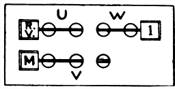
Fig. 605.--To use galvanometer of Leeds and Northrup fault finder in series with the battery: Set switches as shown, and connect between posts Gr. and 2 (see figs. 587 and 588). The galvanometer will have the maximum sensibility with the pointer at 1,000 and the minimum at zero.
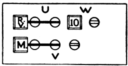
Fig. 606.--To measure high resistances, such as the resistances of faults with Leeds and Northrup fault finder. First Method.--Arrange the switches as shown in the figure. Connect posts Gr. and 2, turn the handle until the galvanometer needle comes to rest at an even deflection of ten divisions. Call the reading A. Connect in the unknown resistance between Gr. and 2. Now close the switch W, so that the figure 1 appears on the top of the block, and again bring the galvanometer to a deflection of ten divisions and call the reading B. Then X = (10,000 B ÷ A) - 1,000. In case X be a high resistance, it will be found that the galvanometer will not deflect ten divisions for any position of the pointer. In such case, choose a number of divisions which is a factor of ten, such as 5, 2, or 1, and multiply (10,000 B ÷ A) by ten divided by the number chosen, as 10/5, 10/2, 10/1. For example, for a deflection of two divisions: X = (10/2)(10,000 B ÷ A) - 1,000. The satisfactory range of the set for high resistance measurement may be increased by using an outside battery of higher voltage. With the contained battery, satisfactory measurements can be made up to 1 or 2 megohms. When outside battery is used, connect one terminal to the post Ba, and the other to 2 for the reading A. Connect the battery and unknown resistance in series between these posts for the reading B. When an outside pressure of 25 volts or over is used, the switch W should not be closed unless there be a resistance in series with the battery of 10,000 ohms or over. Second Method.--For use as a voltmeter to measure high resistances. (More convenient but not quite as accurate as first method.) Set the switches to RV, M and 10. Turn the knurled nut on the galvanometer so as to set the needle to the extreme right hand side of the scale. Connect the posts 2 and Gr. with a short piece of wire. Turn the rotating pointer on the scale until the galvanometer needle moves over about 20 scale divisions when the battery key is closed. Remove the connection between 2 and Gr. as the voltmeter terminals. This makes a simple way of testing for various kinds and amounts of trouble. On a wet cable a deflection of 10 to 15 divisions indicates heavy enough trouble to locate with the fault finder. With a little care, trouble showing only 5 or 6 divisions can be located.
[523] Before attempting locations for opens it is well to make the following measurements:
1. The insulation of the broken wire and the insulation of the good wire with which it is to be compared.
This may be done as shown in fig. 606. It is best that the insulation resistance be fairly good, but experiments indicate that good results can be obtained by the methods which follow, even when the insulation is as low as 100,000 ohms, and fair results when as low as 50,000 to 100,000 ohms.
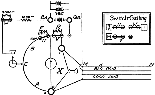
Fig. 607.--Diagram of connections in testing for opens with Leeds and Northrup fault finder. The apparatus required consists of fault finder, buzzer, dry cell to operate buzzer, small induction coil, and telephone receiver. Connect the battery to the primary of the induction coil, one terminal of the secondary to the post Ba, and the other to the connected wires as shown. Set switches U and V so as to short circuit the two resistance coils.
2. The resistance between the two sections of the broken wire should be measured.
This may be done by joining the broken wire and a good wire at the distant end of the cable and measuring the resistance of the loop. To ensure close locations, this resistance should be over 100,000 ohms. Fair [524] locations can be made when the resistance is much lower and it is worth while to attempt it even if the resistance be as low as 10,000 ohms. The difficulty of determining the balance point increases as the resistance decreases.
Ques. Describe the method of locating an open with a fault finder.
Ans. (Case I) The broken wire will be one of a pair. Select another pair in the cable that will have the same capacity per mile and join together the mate of the broken wire and one wire of the other pair. Make the connections as shown in fig. 607, then depress the battery key and move the contact to the point of minimum sound in the telephone. The distance to the break is equal to LA ÷ (1,000 - A), where L is the length of the good wire.
[525] EXAMPLE: A cable 1.45 miles long contained a broken wire. It was found that the insulation resistance of the end of this wire was over 10 megohms, as was that of the good pair selected to test against it. The resistance between the two pieces of the good wire was also over 10 megohms. Connections were made as in fig. 607, and it was found that the balance point was 476. Accordingly from the table
A / (1,000 - A) = 0.9084
and
d = 1.45 × .9084 = 1.317 + miles.
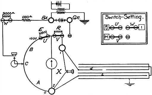
Fig. 608.--Diagram of connections in testing with Leeds and Northrup fault finder for open wire in telegraph and other cables in which the wires are not grouped in pairs. Connect the broken wire to 1. Select a good wire and join to 2. Connect all other wires and ground them, by connecting to the cable sheath. Connect the distant end of the broken wire to the others. Ground the end of the induction coil that is not connected to the post Ba.
Location of Opens.--(Case II) Open wire in telegraph or other cables in which the wires are not grouped in pairs. The connections are made as in fig. 608, and the measurement and calculation exactly as in the preceding case.
The accuracy of the location of both of the above methods depends on the good and broken pair, or the good and broken wires having equal and uniform capacity per unit length. It is not always possible to select [526] wires that are alike in this respect. In such cases, as for instance, where there is no good wire in the cable containing the broken wire, and a good wire has to be selected from another cable, the method of Case III may be used.
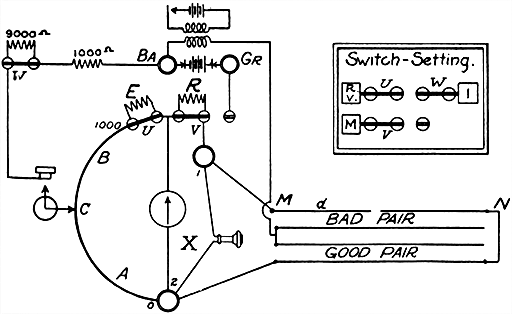
Fig. 609.--Diagram of connections for reading in testing for opens with Leeds and Northrup fault finder, when broken wire and good wire are not in the same cable.
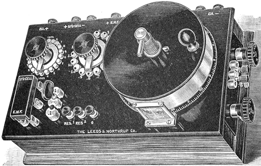
Fig. 610.--Leeds and Northrup potentiometer. It is direct reading from .000001 volt to 16 volts, and with accessories the range may be extended to 1600 volts, and currents may be measured up to 3000 amperes. The instrument has fifteen coils of 5 ohms each, which are in series with an extended wire about 190" long of equal resistance. The electrical circuits are shown in the diagram fig. 611. It is well for the user to open up the potentiometer and make himself familiar with its interior construction, in order to fully understand the operation of the rheostat and other parts. There are no contact resistances in the potentiometer circuit proper. The potentiometer has low internal resistance which gives it the maximum sensibility. Compared with high resistance potentiometer, this is especially advantageous in measuring the electromotive force of thermocouples, and the fall of potential across standard low resistances. As constructed, the last one-tenth volt is covered by the extended wire and the handle which carries the contact point on the wire may be manipulated rapidly so that a fluctuating voltage may be accurately followed. When used with any cadmium cell, the potentiometer is direct reading. The accuracy of the potentiometer resistances can be verified with the facilities of the ordinary laboratory.
Location of Opens.--Case III, in which the broken wire and good wire are not in the same cable. Connect the good wire and broken wire in the same way as shown in fig. 607, and set the pointer for a balance. Call the reading A. Then connect the good wire and the broken wire at the distant end and set the pointer for a new balance. Call this A'. The connections for this reading are shown in fig. 609. The distance to the break will be
where L is the total length of the broken wire.
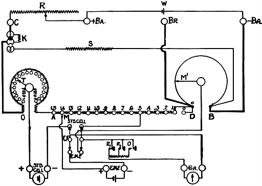
Fig. 611.--Diagram showing connections of Leeds and Northrup potentiometer. The coils in the series AD are each 5 ohms, and between each two there is a brass block with a reamed hole. A pair of flexible cords with taper plug terminals to fit these holes is furnished. These coils can be measured with an ordinary Wheatstone bridge and thus compared with each other to a high degree of accuracy, even if the bridge be not accurate. For potentiometer work, the essential point is that they should be like each other, not that they should be accurately any particular value. In the same way the resistance of the extended wire can be compared with the resistance of the coils in AD. Its resistance should be 1.1 times the value of any coil between A and D. Outside connection with the extended wire may be made by using the posts marked BR and -BA. This adjustment for balancing an unknown electromotive force is accomplished by the manipulation of the two contact points M and M'. The coils AD are arranged in a circle, a revolving switch moving M. A checking device enables the operator to set this switch without taking his eye from the galvanometer. The resistance S is of such value that when it shunts the wire OB, the total resistance between O and B is 1/10 of the same unshunted. When the shunt is applied, provided the total current remain the same, the drop between any two points on AB will be 1/10 of its previous value. The total current will remain the same provided the total resistance in the circuit remain the same. This is accomplished by making the coil K such that it exactly compensates for the reduction in resistance caused by plugging in the shunt coil S. The low scale is applied by moving the plug from the position 1 to the position .1. With this change the potentiometer reads from .16 volt down by indicated steps of .000005 volt. The reading is very simple. For instance, if M stand at 1.2 and M' at 1.35 revolutions, the reading is 1.2135 volts. The resistances of the instrument are wound upon metal spools, and are therefore able to dissipate a comparatively large amount of energy. This allows the potentiometer to be used for pressure measurements up to 16 volts without the use of a volt box.
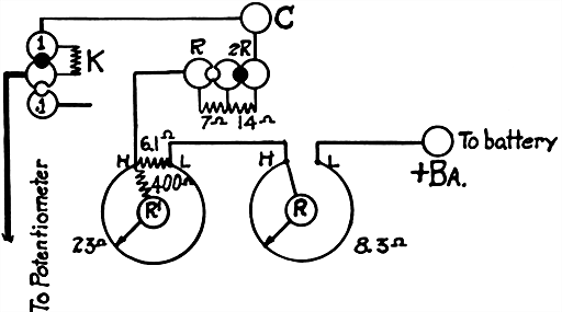
Fig. 612.--Diagram showing actual connections in the rheostat of Leeds and Northrup potentiometer. The figure corresponds to R of fig. 611. The rheostat is mounted in the end of the potentiometer as shown in fig. 610. Rough adjustment of the potentiometer current is made by means of the variable resistance R. Fine adjustment is made by means of the variable resistance R'. It will be noted that the 23 ohm resistance of this latter rheostat is shunted by a resistance of 6.1 ohms, making possible a very fine regulation. Further, there is in series with the moving contact a resistance of 400 ohms, which makes the effect of variable contact resistance negligible. Only one cell of storage battery should be used. When this battery is fresh, the plug shown in the figure at 2R should be inserted at R. This gives the greatest resistance in the rheostat circuit. As the cell runs down, the plug should be changed to 2R. When both plugs are in, the rheostat slide wires are in series with the potentiometer circuit.
EXAMPLE: A pair of wires containing one broken wire was connected with a good pair in a different cable as shown in fig. 607. The reading A was found to be 180. The good and bad wires were then joined at the distant end as in fig. 609, and the reading A was found to be 88. The total length of the bad wire MN was 1.44 miles. Required, the distance to the break. Substituting the values in the formula:
d = 180 × 88 × 1.44 / 1,000(180 - 88) + 180 × 88 = .211 + mile.
[529] To Pick Out Faulty Wires in a Cable.--Short circuit the coils E and R with switches U and V. Set the pointer at 1,000. Connect the post Gr. to ground or the cable sheath and apply the wires one after another to the binding post 2. The galvanometer will deflect for a faulty wire.
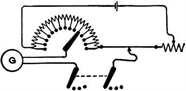
Fig. 613.--Diagram of the Crompton potentiometer. In this instrument the resistance consists of fourteen coils, each of 10 ohms, in series with a straight wire, also 10 ohms resistance, thus forming a system of fifteen equal steps. Across the whole a pressure of 1.5 volt is applied from a secondary cell, thus providing .10 volt per step. Any fraction is then tapped off by means of a radial switch on the resistance coils and a sliding contact on the wire. The standardization is performed by adjusting a resistance in series with the whole until the standard cell employed indicates, by means of the galvanometer G, a balance at the point which represents its electromotive force on the basis given above.
Ques. What is a potentiometer?
Ans. An arrangement of carefully standardized resistances for measuring voltages in comparison with a standard cell. It is used for accurate measurement of voltages, currents, and resistances.
In place of a series of standardized resistances, a slide wire may be used as in fig. 614.
Ques. Describe one form of potentiometer.
Ans. As shown in fig. 614, it consists of a fine German silver wire about 3 feet long stretched between the binding posts A, B, [530] which are attached to a wooden base carrying a scale divided into 1,000 equal parts. There are three circuits, the terminal A being included in each, one including the battery, and the other two the galvanometer. A three point switch connects the galvanometer in series with the standard cell SC, or the cell to be tested C, the circuits being completed by leads terminating in the sliding contacts M and S.
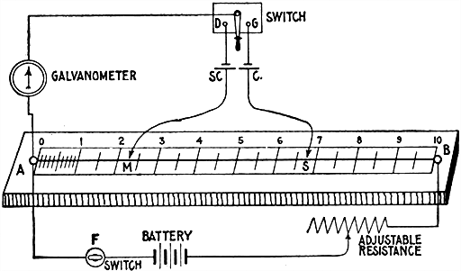
Fig. 614.--Diagram of potentiometer showing method of measuring the voltage of a cell. The potentiometer is simply a high resistance wire of uniform diameter stretched between two binding posts, A and B, in such a way that contact can be made at its ends and along its length. Necessary circuits are plainly shown in the figure; SC, is a standard cell and C, the cell to be tested. M, and S are sliding contacts, connecting with the "slide wire."
Ques. Describe the method of measuring the voltage of a cell with a potentiometer.
Ans. Fig. 614 shows a method of comparing a pressure with that of a standard cell and is applicable whether the pressure of the cell to be tested be greater or less than that of the standard cell. In making the test the switch F is first closed, then the other switch is moved to D, and M adjusted till galvanometer shows no deflection; similarly, the switch is moved to G, and S adjusted till galvanometer shows no deflection. Then, C:SC = AS:AM. from which C = SC × AS ÷ AM.
[531] EXAMPLE.--Let 1.016 volts be the known voltage of the standard cell SC, and the scale reading of AS be 657, and of AM, 225 as in the figure, then
C = (1.016 × 657) / 225 = 2.966 volts
The arrangement may, however, be made direct reading, that is, the slide wire may have a scale of volts instead of lengths or resistances, as follows: Suppose the standard cell to have a pressure of 1.434 volts, the sliding contact M is placed at the reading 1.434, and the adjustable resistance varied till the galvanometer shows no current. This means that the pressure between A and M is 1.434, and consequently the pressures all along the slide can be read off the scale in volts. Hence, when S has been adjusted to balance, the pressure of C is read off the scale in volts.
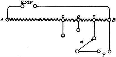
Fig. 615.--To measure a pressure greater than 1.6 volts with Leeds and Northrup potentiometer by using a volt box or multiplier. To measure high voltages it is necessary to connect the voltage across high resistance and to measure on the potentiometer a definite fraction of the total drop. In the figure, AB is a high resistance of which CB is .1th, DB .01th, and EB .001th of the total resistance. The potentiometer reading is accordingly multiplied by 10, 100, or 1,000, depending upon whether the switch M is set on C, D, or E. Resistance boxes for this purpose are called volt boxes, and are constructed to multiply the potentiometer readings by 10, 100, and 1,000. In using them, it is only necessary to connect the unknown E.M.F. at the posts so marked, and the potentiometer to the posts marked P. The potentiometer reading is taken as above and multiplied by a factor depending upon the position of the switch M, which factor is indicated upon the box. It is essential in making these connections that the polarity be carefully observed.
How to Use a Potentiometer.--All connections must be made as indicated by the stamping on the instrument. Particular attention must be given to the polarity of the standard cell, of the battery, and of the voltage, the corresponding + and - signs being marked. If used with a wall galvanometer having a telescope and scale, it will be found convenient to place the potentiometer so that the telescope is directly over the glass index of the extended wire, thus permitting the observer to read the galvanometer deflections and potentiometer settings without changing his position.
Potentiometer Current.--A medium sized storage cell will be found desirable, producing a steady current. Errors in measurements are frequently made by using an unsteady current.
Setting for Standard Cell.--Set the standard cell to correspond with the certified pressure of the standard cell as given in its certificate. In using the potentiometer shown in fig. 610, place the plug in hole 1, and see that it is always in this position when checking against the standard cell. Place the double throw switch at STD. CELL.
Adjust the regulating rheostat until the galvanometer shows no deflection. In making the first adjustment use the key marked R1; when a balance is almost attained, use key R2, and for the final adjustment use key marked R0. This cuts out the resistance in series with the galvanometer and gives the maximum sensibility.
Measurement of Unknown Pressure.--The potentiometer (fig. 610), as ordinarily used, gives direct readings for voltages up to and including 1.6 volts. For pressures higher than 1.6 volts, a volt box or multiplier should be used. After obtaining the standard cell balance, [532] as previously described, place the double throw switch in the position marked E.M.F. The balance for the unknown E.M.F. is obtained by manipulating the tenths switch and rotating the contact on the extended potentiometer wire. The final position of the two contacts in conjunction with the position of the plug at the left of the instrument indicates the voltage under test.
As directed above, use key R1 for rough adjustment, R2 for intermediate adjustment, and key R0 for final adjustment.
Plug at 1 gives readings for voltage directly from settings of tenths switch and extended wire contact.
Plug at .1 shunts the potentiometer circuit so that the voltage measured is .1 of the reading taken directly from the scale. Hence, the readings taken from the setting of the tenths switch and the slide wire contact must be divided by 10.
To Balance Galvanometer for Unknown Voltage.--Place plug in hole 1 (fig. 610) for voltages up to 1.6, and in hole .1 for voltages up to .16. Rotate the tenths switch until a condition of balance is obtained exactly or approximately. To secure an exact balance, rotate the contact on the extended wire. The unknown voltage can now be read directly from the position of the tenths switch and the extended wire contact if plug be at 1, or by dividing by 10 if plug be at .1.
[533] EXAMPLE.--A balance was obtained with the tenths switch at 1.3, the extended wire contact at 176 and the plug at 1. The voltage under test, therefore, is 1.3176. If the plug at .1 had been used, the same reading would have indicated .13176.
To ascertain if the current in the potentiometer circuit has altered during a measurement, it is only necessary to plug in at 1, place the double throw switch on STD. CELL and close the galvanometer key. No deflection indicates that the current has not changed. If the galvanometer deflect, the regulating rheostat must again be adjusted until the galvanometer shows no deflection.
To Measure Voltages from 1.6 to 16.--Pressures up to 16 volts may be measured by using a greater voltage across the BA posts (fig. 615). For this purpose a battery of about 20 volts should be used. Insert the large plug at .1 and throw the switch to STD. CELL, then balance the galvanometer by means of the regulating rheostat. When the rheostat has been set to secure a balance, insert the large plug at 1, set the switch on E.M.F. and read the voltage in the usual manner. Multiply the reading by 10.
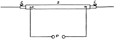
Fig. 616.--Measurement of current with potentiometer. This is done by measuring the drop in volts across a known low resistance. In the figure S is the standard resistance, and on it are the pressure terminals pp, and the current terminals CC. The potentiometer is connected to the shunt through the posts marked P. The resistance between the points pp is adjusted to an even fraction of an ohm. These resistances are so chosen that in order to determine the current passing through the shunt, after having obtained a potentiometer balance it is only necessary to multiply the potentiometer reading by a simple factor. For instance, in using a .01 ohm standard. It is only necessary to multiply the potentiometer reading by 100, which gives the current reading in amperes; similarly, a .1 ohm requires multiplication by 10, and a .001 ohm by 1,000.
Care of Potentiometer.--The slide wire, although protected to a great extent by the hood, in time accumulates dust and dirt with a thin film of oxide. This will tend to increase [534] the resistance in this part of the circuit owing to poor contact. This wire should, therefore, be cleaned occasionally.
To do this, unscrew the stop against which the hood strikes when turned to read zero; then remove the hood and rub the entire slide wire vigorously with a soft cloth dipped in vaseline. Do not use emery or sand paper as this will destroy the uniformity of the slide wire. Clean also the steel contact which rubs on the wire, as this becomes glazed after much use. When the potentiometer is not in use, the hood should be screwed all the way down, and the lid put in place to exclude dust.
If it be used in a chemical factory, laboratory, or any place where acid fumes are prevalent, this latter precaution is important, because the fumes may attack the slide wire.
It is also well to keep the contact surfaces of the switch studs clean and bright by wiping them occasionally with a soft cloth dipped in vaseline.

Res. of leads on each end is equal to 10 divisions of slide wire. The slide wire is divided into 1000 parts--20 for the leads, or 980 divisions. Calibrated scale on Galvanometer:
Fig. 617.--Diagram of Leeds and Northrup bridge for locating faults in power circuits, showing arrangement of the connections including the lead cables and galvanometer contacts. Make connections as shown. The clamps must be so fastened at A and C that the contact resistances will be very small. This contact resistance will figure as an error in the measurement. If, for instance, the contact resistance were equal to .001 of an ohm, and the wire were of such a size that .001 of an ohm were equal to the resistance of 20 feet of the cable, there would be an error of 20 feet in the location of the fault. For this reason all contact resistances throughout the loop from A to C must be extremely small. The battery is to be connected to the posts marked Ba., and the post marked Gr. is to be grounded. It will very frequently happen that the ground is to the cable sheath or some other conductor. In this case, the binding post Gr. should be grounded to this conductor. Sufficient battery should be used to give a readable deflection on the galvanometer for a small movement of the contact on the bridge wire. The fault is located by the usual Murray formula. If, for instance, the galvanometer show no deflection when the contact is at 300 on the scale, it would indicate that the fault is at a distance from A equal to .003 of the total length of the loop from A to C. A testing current of five amperes may be used with this bridge. In cases of necessity, this current may be increased to eight amperes, but when this current is used it should not be allowed to pass through the bridge for a longer time than is necessary. It frequently happens that small faults which have a very high resistance develop in high pressure cables. Such faults are likely to break down and result in damage and should be located. It is usually impossible to locate these faults until they have been partially carbonized. This must be done by applying a sufficiently high voltage between the cable and the sheath (or whatever it is grounded on) to break down the fault. In order to prevent the breaking down process from resulting in a serious burn out a high resistance must be placed in the circuit which will prevent an excessive current, or the circuit must be carefully fused. The former procedure is the better.
[535] Location of Faults where the Loop is Composed of Cables of Different Cross Sections.--Faults in loops of this character may be located with the same degree of accuracy as those in loops of a uniform cross section, provided the length and cross section of each length of cable are known. An example will illustrate the method:
In the diagram, fig. 617, assume the length of the cable AE to be 550 yards of 25,000 cir. mil., EF, 500 yards of 40,000 cir. mil., and FC, 1,050 yards of 30,000 cir. mil. These lengths must be reduced by calculation to equivalent lengths of one [536] size, and for this purpose it is best to select the largest size. The results of this calculation are as follows:
This makes the total resistance of the loop equivalent to 2,780 yards of 40,000 cir. mil. If the contact show a balance for a reading of 372.5, this indicates that the fault is at a distance of 372.5/1,000 of 2,780 = 1,035.5 equivalent yards. Of this, 880 are in the stretch A E. Consequently the fault is:
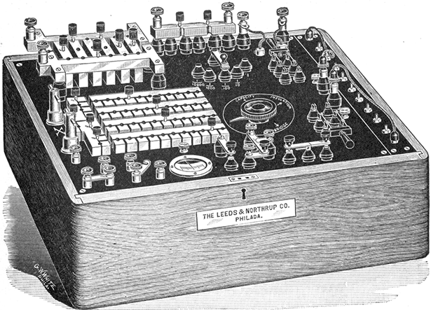
Fig. 618.--The Fischer portable cable testing set, designed for locating crosses, grounds and breaks in cables, also for conductor and liquid resistance measure. The distinguishing feature of the set is the master switch. By means of this switch, connections can be made for the various tests by a single movement, thus avoiding the labor and time which have to be expended in interchanging the connections and memorizing the rather complicated scheme of connections.
An ammeter or ampere meter is simply a commercial form of galvanometer so constructed that the deflection of the needle indicates directly the strength of current in amperes. A good ammeter should have a very low resistance so that very little of the energy of the current will be absorbed; the needle should be dead beat, and sufficiently sensitive to respond to minute variations of current.
According to the principle of operation, ammeters and voltmeters are classified as:
Again, they are divided according to their use into two classes:
[538] Milli-ammeters or milli-voltmeters are instruments in which the scale is graduated to read directly in thousandths of an ampere or thousandths of a volt respectively.
Ques. Describe the moving iron type instrument.
Ans. The arrangement of the working parts are shown in fig. 620. A soft iron needle N, is pivoted inside of a coil C, and is held out of line with the axis of the coil by means of a permanent magnet M, when the instrument is idle. In this position, a pointer P, which is attached to the needle, stands at the zero mark of the scale S. If a current be passed through the coil, magnetic lines of force are set up in its center, which tend to pull the needle into line with them, and therefore with the axis of the coil. This pull is resisted by the permanent magnet M, and the amount of deflection of the needle from the zero position depends upon the strength of the current or the voltage according as the coil is wound to indicate amperes or volts.
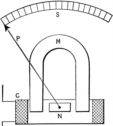
Fig. 620. Moving iron type instrument. The essential parts are: N, soft iron needle; C, coil; M, permanent magnet; P, pointer; S, scale. Current passing through the coil acts on the needle, causing it to turn against the restraining force due to the influence of the permanent magnet.
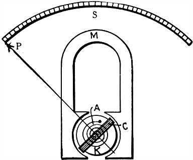
Fig. 621.--Moving coil type instrument. The essential parts are: A, spiral spring; C, coil; K, soft iron core; M, permanent magnet; P, pointer; S, scale. Current passing through the coil causes the moving system to turn against the restraining force due to the influence of the permanent magnet.
Ques. Describe a moving coil instrument.
Ans. This type of instrument is shown in fig. 621. It consists of a moving coil C, to which is attached the pointer, and which is pivoted between the poles of a permanent magnet M. The coil moves between these poles and a fixed soft iron core K, and is held in the normal position by two spiral springs A, above and below the core. The springs also serve to make electrical connection with the coil C.
When a current passes through the coil, magnetic lines are set up in it which are at an angle to those passing from one pole of the permanent magnet to the other. The lines of force, which formerly passed from one pole of the magnet to the other by straight lines or by short curved ones, are "stretched" on account of the field produced by the current in the coil, and, in trying to shorten themselves, tend to twist the coil through an angle. This tendency to move is resisted by the two spiral springs, hence the coil moves until equilibrium is established between the two opposing forces.
The amount of deflection of the pointer depends, either upon the current strength, or the voltage according to the winding of the coil.
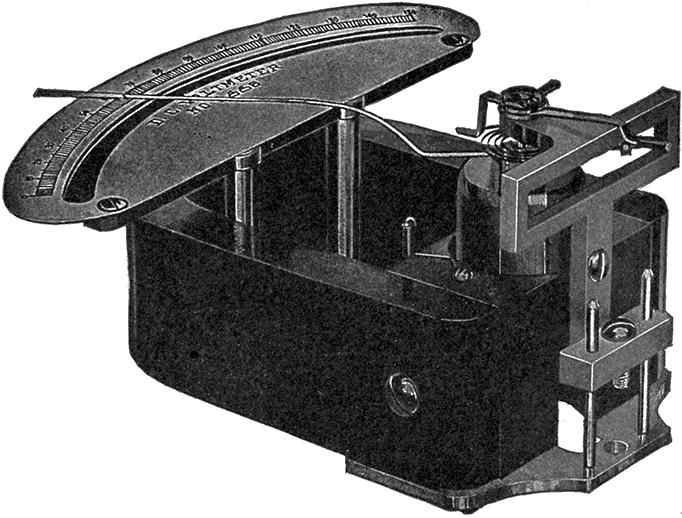
Fig. 622.--Keystone voltmeter; view showing the moving element being withdrawn by loosening one screw. These instruments are constructed on the d'Arsonval system, the moving element being shown in detail in figs. 623 and 624. The entire system is mounted upon a solid metal base plate. The permanent field magnet is made of a single piece of magnet steel, and the pole pieces are of soft steel, permanently secured to the magnet in order that the distribution of the magnetic flux will not be changed by removal and replacement of the pole piece. Accordingly the moving mechanism is mounted separately from the field, so that it can be readily lifted from the field without removing the pole pieces. The function of the core is to secure a uniform field. The moving coil is wound upon a form of aluminum, which serves the purpose of damping by the generation of eddy currents. The winding of the coil is of fine copper wire, to which current is conveyed by means of the controlling springs and which, in the case of a voltmeter, is connected in series with a resistance, and in the case of an ammeter, across the terminals of a shunt.
[541] Ques. How does the winding differ in ammeters and voltmeters?
Ans. An ammeter coil consists of a few turns of heavy wire (when designed to carry the full current), while a voltmeter coil is wound with many turns of fine wire. Thus, the ammeter is of low resistance, and the voltmeter of high resistance.
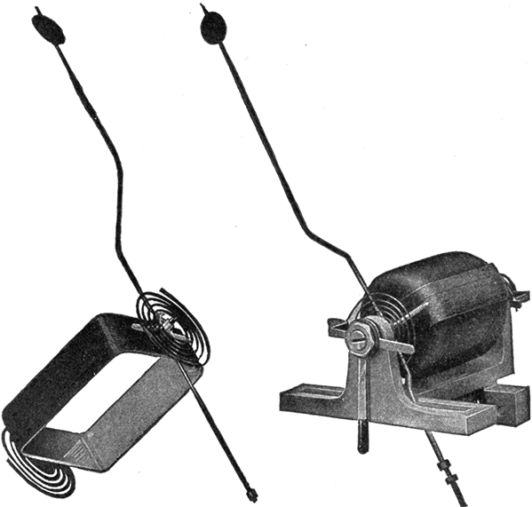
Fig. 623.--New moving element of Keystone instruments, weight 1.2 grams.
Fig. 624.--Moving element of Keystone instruments assembled in bearing. The moving element consists of coil, counterpoise and pointer. The mechanical connections are made by means of screws and steady pins. In order to adjust for slight set or subset of spring under long use a zero adjuster is provided by means of which this set can be connected and the pointer brought back to zero.
[542] Ques. Why is a high resistance coil used with a voltmeter?
Ans. As actually constructed, most voltmeters are simply special forms of ammeter. From Ohm's law, the current through a given circuit equals the pressure at its terminals divided by its resistance. Hence, if a high resistance be connected in series with a sensitive ammeter that will measure very small currents, then the current passing through the circuit is directly proportional to the voltage at its terminals, and the instrument may be calibrated to read volts.

Figs. 625 and 626.--Connections for series and shunt ammeters. When the construction is such that all the current passes through the instrument, it is connected as in fig. 625, but where the instrument is designed to take only a fraction of the current, it is connected across a shunt, as in fig. 626, a definite proportion of the current passing through the instrument and the remainder through the shunt.
Ques. Into what two classes may ammeters be divided?
Ans. They are classed as series or shunt according to the way they are designed to be connected with the circuit.
Ques. What determines the mode of connecting ammeters?
Ans. When the wire of the ammeter coil is large enough to carry the whole current, it is connected in the circuit in series as shown in fig. 625. If, however, the wire be small, the instrument is connected in parallel with a shunt of low resistance, so that it only carries a small part of the current, as in fig. 626.
[543] For circuits which carry large currents, the shunt connection is always used, because otherwise the coil of the ammeter would have to be very heavy and the instrument correspondingly bulky.
Ques. How are shunt ammeters arranged to correctly measure the current?
Ans. The coil is arranged so that a definite proportion of the whole current passes through it. A large conductor of low resistance is connected directly between the two terminals or binding posts of the instrument; the coil is connected as a shunt around a definite part of this main conductor; then, since the two are connected in parallel and each branch has a definite resistance, the current divides between the two branches directly in proportion to their relative conductivities, or inversely according to their resistances. The coil, therefore, takes a definite part of the whole current, and the force moving it and its pointer away from the zero position is directly proportional to the whole current. Hence, by providing a proper scale, the value of the entire current will be indicated.

Figs. 627 and 628.--Westinghouse ammeter shunts. These shunts are used where heavy currents are to be measured. The shunt is connected in series with the bus bar or circuit to be measured, and its terminals are connected by means of small leads to the ammeter or other instrument. These shunts are designed to have approximately 50 millivolts drop at full rated current. They are intended primarily for Westinghouse meters, but can be used satisfactorily with any meter requiring 50 millivolts for full scale deflection.
Ques. How is a voltmeter connected?
Ans. A voltmeter is always connected to the two points, whose difference of potential is to be measured.
[544] For instance, to measure the voltage between the two sides A and B of the circuit shown in fig. 629, one terminal of the voltmeter is connected to wire A, and the other to wire B. If the "drop" or difference in voltage through a certain length of wire L, of a circuit, as from A to B in fig. 630 is to be determined, one terminal of the voltmeter is connected to A and the other to B. In a similar manner is found the drop through a lamp.

Fig. 629.--Voltmeter connection for measuring the pressure in an electric circuit. The voltmeter is connected in parallel in the circuit at the point where the voltage is to be measured.
Fig. 630.--Voltmeter connection for measuring the "drop" or fall in voltage in a certain length of wire, as for instance, the length between the points A and B. The voltmeter is shunted between the two points whose pressure difference is to be measured.
Ques. What is the difference between a voltmeter and an ammeter?
Ans. A voltmeter measures pressure, while an ammeter measures current. As actually constructed, most voltmeters are simply special forms of ammeter.
If a high resistance be connected in series with a sensitive ammeter that will measure very small currents, then the current passing through the circuit is directly proportional to the pressure or voltage at its terminals and the instrument may be calibrated to read volts.
Ques. Explain the term "calibrate."
Ans. To calibrate a measuring instrument is to determine the variations in its readings by making special measurements, or by comparison with a standard.
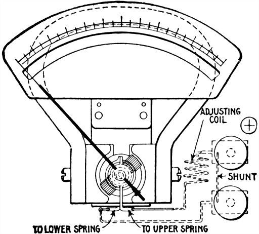
Fig. 631.--Weston ammeter; view showing shunt enclosed within the instrument. Weston instruments are direct reading and dead beat. Although the scales have practically uniform divisions, it is not assumed in the calibration that they are uniform, and the scales are not printed or engraved. The method of calibration consists in laying out each large division of the scale by comparing the instrument with a standard, and then inking in the division lines so found. The smaller divisions between the large ones are then equally spaced and marked by a mechanical method.
Fig. 632.--Weston portable voltmeter, inspector's style. This instrument is provided with a reversing key. Instead of the regular binding posts, pins are used with which connections are made by means of contact cups attached to flexible cords. These contact cups are convenient in making connections, or in changing quickly from one range to the other, if the instrument have a double scale. Connections for the different ranges are made in precisely the same way as with the regular double scale voltmeters. For the upper scale values, the contact pin to the right and the front contact pin to the left being taken, and for the lower scale values, the left contact cup is changed to the rear contact pin.
[546] Ques. Describe a solenoid or plunger ammeter.
Ans. This type consists of a "plunger" or soft iron core arranged to enter a solenoid. Current being passed through the wire of the solenoid causes the core to be more or less attracted against a restraining force of gravity or springs. A pivoted pointer attached to the core indicates the current value on a graduated dial as shown in fig. 633.
Ques. What are the objections to plunger instruments?
Ans. They are not reliable for small readings, and are readily affected by magnetic fields.
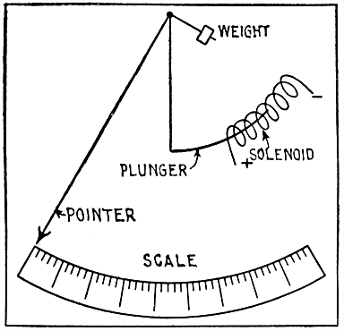
Fig. 633.--Plunger type instrument. The current to be measured passes through the solenoid, producing a magnetic effect on the soft iron plunger which tends to draw it into the coil, and thus cause the pointer to move over the graduated scale. The distance the rod moves depends on the value of the restraining force (which may be springs or gravity), the coil winding, and strength of current. The winding consists of a few turns of heavy wire for an ammeter, and a large number of turns of fine wire when constructed as a voltmeter. Since the iron has a certain amount of residual magnetism, the deflection with smaller following large currents is more than would be produced by the same current following a smaller one. The instrument therefore is less reliable than the usual types.
Ques. Describe a magnetic vane instrument.
Ans. It consists of a small piece of soft iron or vane mounted on a shaft that is pivoted a little off the center of a coil as shown in fig. 634. The principle upon which the instrument works is [547] that a piece of soft iron placed in a magnetic field and free to move will move into such position as to conduct the maximum number of lines of force. The current to be measured is passed around the coil producing a magnetic field through the center of the coil. The magnetic field inside the coil is strongest near the inner edge, hence, the vane will move against the restraining force of a spring so that the distance between it and the inner edge of the coil will be as small as possible. A pointer, attached to the vane shaft moves over a graduated dial.
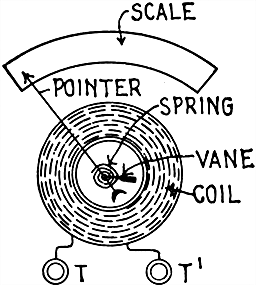
Fig. 634.--Magnetic vane instrument. A soft iron vane, eccentrically pivoted within a coil carrying the current to be measured, is attracted toward the position where it will conduct the greatest number of magnetic lines of force against the restraining force of a spring or equivalent.
Ques. Describe an inclined coil instrument.
Ans. As shown in fig. 635, a coil carrying the current, is mounted at an angle to a shaft to which is attached a pointer. A bundle of iron strips is mounted on the shaft. A spring restrains the shaft and holds the pointer at the zero position when no current is flowing. When a current is passed through the coil, [548] the iron tends to take up a position with its longest sides parallel to the lines of force, which results in the shaft being rotated and the pointer moved on the dial, the amount of movement depending upon the strength of the current in the coil.
The coils for large sizes are generally wound with a few turns of flat insulated copper ribbon. The instruments are adapted to either direct or alternating currents but are recommended for alternating currents.
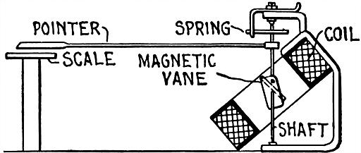
Fig. 635.--Thompson inclined coil ammeter. It is constructed on the magnetic vane principle in which an iron vane is attracted by the magnetic field due to the coil, so as to turn itself parallel with the axis of the coil, the latter being inclined with respect to the axis of the vane. The voltmeter of this type has a similarly placed stationary coil, but in place of the iron vane, is provided with a moving coil in series with the other coil. The restraining force in each case being that due to springs. Figs. 636 and 637 show the actual construction of inclined coil instruments.
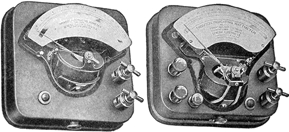
Figs. 636 and 637.--Thompson inclined coil portable indicating instruments. Fig. 636, ammeter type P interior; fig. 637, wattmeter, type P, interior. These instruments, though primarily designed for use on alternating current circuits, may also be used on direct current circuits, by making reversed readings and taking the mean as the true indication. The voltmeters and wattmeters are constructed on the dynamometer principle and the ammeters, on the magnetic vane principle. The voltmeters and wattmeters are provided with a contact key which may be locked in position, enabling the instruments to be left constantly in circuit. The movements of the pointer are damped by means of an air vane; there is also a friction damping device operated by a small button to check excessive oscillations of the pointer. The inclined coil instruments are so designed that the torque is sufficiently high to insure the pointer assuming a definite position with each change in current value.
Ques. What is the principle of the hot wire instrument?
Ans. Its action depends upon the heating of a conductor by the current flowing through it, causing it to expand and move an index needle or pointer, the movements of which, by calibration, are made to correspond to the pressure differences producing the actuating currents.
Ques. What are the characteristics of hot wire instruments?
Ans. Voltmeters of this type are not affected by magnetic fields, and as their self-induction is small, they can be used on [549] either direct or alternating currents; but they possess certain serious defects: they consume more current than the other types; cannot be constructed for small readings; are liable to burn out on accidental overloads; and are somewhat vague in the readings near the zero point and are sometimes inaccurate in the upper part of the scale.
Ques. Describe the construction and operation of the Whitney hot wire instruments.
Ans. As shown in fig. 638, a wire AX, of non-oxidizable metal, of high resistance and low temperature coefficient, passes over a pulley B mounted on the shaft C. The ends of the wire are attached to the plate E at its ends F and G, the wire being insulated from the plate at G. A spring H holds the wire in tension and takes up the slack due to the expansion caused by the heating of the wire when a current passes through it. The current [550] flows only in the portion of the wire marked A, between the plate E and the pulley B up to the point K where the connection is shown. When a current flows through the wire A, the spring takes up the slack, pulls A around B, and causes B to rotate upon its shaft C. It is clear, that a pointer attached to C, would indicate on a scale the movement of B and C, but as this movement is very slight, a magnifying device will be required. This device consists of a forked rod L, rigidly attached to the shaft C, and carrying at its lower end a silk fibre fastened to the fork and passing around a pulley M, to which a pointer N is attached. For direct current measurements only an electromagnetic system is used.
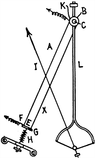
Fig. 638.--Diagram showing principle and construction of the Whitney hot wire instruments. The action of instruments of this type depends on the heating of a wire by the passage of a current causing the wire to lengthen. This elongation is magnified by suitable mechanism and transmitted to the pointer of the instrument.
Ques. What is the principle of electrostatic instruments?
Ans. The action of these instruments depends upon the fact that two conductors attract one another when any difference of [551] electric pressure exists between them. If one be delicately suspended so as to be free to move, it will approach the other.
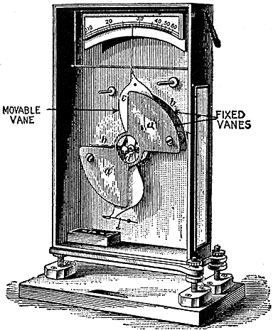
Fig. 639.--Kelvin electrostatic voltmeter; a form of instrument designed for measuring high pressures up to 200,000 volts. The instrument, as illustrated, consists of fixed and movable vanes with terminals connecting with each. These vanes which act as condensers take charges proportional to the potential difference between them, resulting in a certain attraction which tends to rotate the movable disc against the restraining force of gravity. In the figure aa and b are two fixed vanes and c a movable vane, carrying a pointer and having a proper weight at its lower end.
Ques. Describe the Kelvin electrostatic voltmeter.
Ans. A simple form consists, as shown in fig. 639, of a metal case containing a pair of highly insulated plates, between which a delicately mounted paddle shaped needle is free to move. When the needle is connected to one side of a circuit and the stationary plates to the other side, the needle is attracted and moves between them as indicated by the pointer. Adjusting screws at the lower end of the needle allow it to be balanced so that its center of gravity is somewhat below the center of suspension. Gravity then is the restraining force.
[552] The range of the instrument may be changed by hanging different weights upon the needle. By increasing the number of blades the instrument can be made to measure as low as 30 volts. The form having two stationary blades and one movable blade is suitable for measuring from 200 to 20,000 volts. The quadrant electrometer or laboratory form will measure a fraction of a volt.
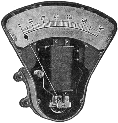
Fig. 640.--Thompson astatic instrument without cover. When current passes through the coils of the moving element, the lines of force parallel to the shaft produce a torque which tends to turn the shaft and cause the needle to travel across the scale. This action is, of course, opposed by the magnetic field at right angles to the shaft acting on the two pieces of magnetic metal. These astatic instruments have no controlling springs. The two small silver spirals which conduct the current to and from the armature are made of untempered silver and exert no force as springs. The actuating and restraining forces are dependent upon the same electromagnets. The damping effect in these instruments is produced by an aluminum disc moving in a magnetic field, and is proportional to the square of the magnet strength.
Ques. Explain the construction and principle of the Thompson astatic instruments.
Ans. The fields of these instruments are electromagnets wound for any specified voltage and provided with binding posts separate from the current posts of the instrument. The moving coils are mounted upon an aluminum disc and are located in a magnetic field which is parallel to the shaft and astatically arranged. Two small pieces of magnetic metal are rigidly [553] mounted on the shaft and the astatic components of the magnetic field, which are perpendicular to the shaft, tend to keep the pieces of magnetic metal in their initial positions. When current passes through the coils of the moving element, the lines of force parallel to the shaft produce a torque which tends to turn the shaft and cause the needle to travel across the scale. This action is, of course, opposed by the magnetic field at right angles to the shaft acting on the two pieces of magnetic metal. There are thus no restraining springs, current being conveyed to the moving coil by torsionless spirals of silver wire. Thompson astatic instruments can be provided with polarity indicators, a red disc showing on the scale card where the poles are reversed.
[554] The effect of external fields is eliminated by the astatic arrangement of the fields and the moving parts. A field which tends to increase the torque on one side of the armature diminishes it to a corresponding degree on the other side. The damping effect in these instruments is produced by an aluminum disc moving in a magnetic field.
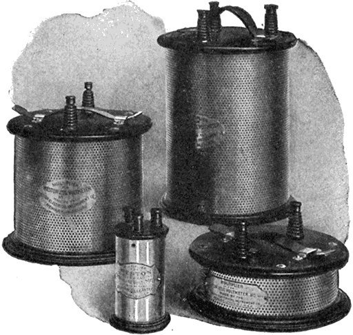
Fig. 641 to 642.--Multipliers for Western standard portable voltmeters. Multipliers are resistance boxes, the coils in which are highly insulated, and are adjusted so that the readings of the instrument may be multiplied by any desired constant. Multipliers are usually constructed so that the indications of the pointer, multiplied by 2, 5, 10, 20 or 50, will give the voltage of the circuit. By the use of multipliers the range of voltmeters may be increased to any practical limit.
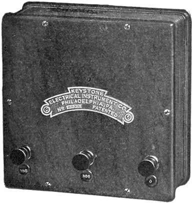
Fig. 643.--Portable multiplier for portable voltmeter. A multiplier is used for increasing the readings of voltmeters, and consists of resistance coils placed in a portable case. A multiplier is connected in series with the voltmeter and must be adjusted for the instrument with which it is to be used, because the resistance coil must be a multiple of the voltmeter resistance. For instance, a multiplier with a value of 10, used with a 6 volt voltmeter or 521 ohms would measure about 5,215 ohms; one with a value of 40, would equal about 20,860 ohms. The multiplier 10 would give a total scale value of 60, and the multiplier 40, a total scale value of 240 volts to the 6 volt instrument. A multiplier is of considerable value in that it does away with the necessity of having a number of voltmeters of different ranges. The instrument here illustrated has a range of 150 volts.
Ques. What are multipliers?
Ans. These are extra resistance coils which are connected in series with a voltmeter for increasing its capacity or readings. They are put up in portable boxes, and must be adjusted for each particular voltmeter as the resistance of a multiplier coil must be a multiple of the resistance of the voltmeter itself.
[555] Ques. What is an electro-dynamometer?
Ans. An instrument for measuring amperes, volts, or watts by the reaction between two coils when the current to be measured is passed through them. One of the coils is fixed and the other movable.
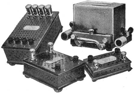
Figs. 644 to 645.--Western standard portable shunts. The milli-voltmeters used in connection with these shunts read directly in amperes. Shunts of different capacities can be adjusted to the same instrument, and it can, therefore, be used to measure a current of 2,000 amperes with the same degree of accuracy as a current of 1 ampere. In selecting shunts of different capacities for use in connection with one instrument it should be considered that the higher ranges must be even multiples of the lower one in order to suit the same scale on the instrument.
Ques. Describe the Siemens' electro-dynamometer.
Ans. The essential parts are shown in fig. 646. The fixed coil A, composed of a number of turns of wire is fastened to a vertical support, and surrounded by the movable coil B of a few turns, or often of only one turn. The movable coil is suspended by a thread and a spiral spring C, below the dials which are fastened at one end to the movable coil and at the other end to a milled headed screw D, which can be turned so as to place the planes of the coil at right angles to each other, and to apply torsion to the spring to oppose the deflection of the movable coil for this position when a current is passed through the coils. The [556] ends of the movable coil dip into two cups of mercury E, E', located one above the other and along the axis of the coils so as to bring the two in series when connected to an external circuit. The arrows show the direction of current through the two coils. An index pointer F is attached to the movable coil. The upper end of this pointer is bent at a right angle, so that it swings over the dial between two stop pins G, G', and rests directly over the zero line when the planes of the coils are at right angles to each other. A pointer H is attached to the torsion screw D, and sweeps over the scale of the dial. The spring is the controlling factor in making the measurement.
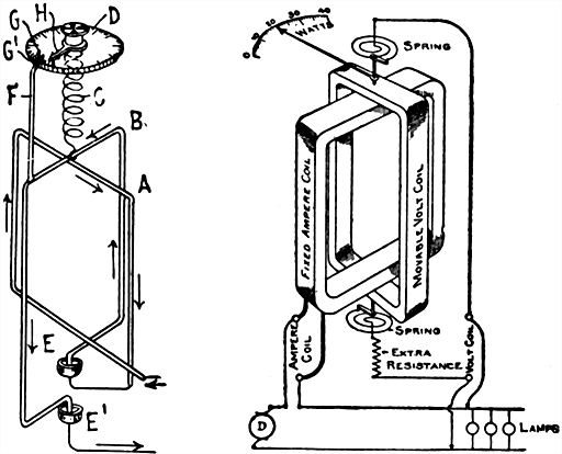
Fig. 646.--Diagram of Siemens' electro-dynamometer. It consists of two coils on a common axis, but set in planes at right angles to each other in such a way that a torque is produced between the two coils which measures the product of their currents. This torque is balanced by twisting a spiral spring through a measured angle of such degree that the coils shall resume their original relative positions. If the instrument be used for measuring current, the coils are connected in series, and the reading is then proportional to the square of the current. If used as a wattmeter, one coil carries the main current and the other a small current, which is proportional to the pressure. The reading is then proportional to the power in the circuit.
Fig. 647.--Diagram showing connections of Siemens' electro-dynamometer as arranged to read watts.
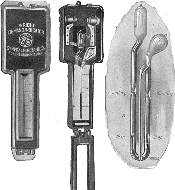
Figs. 648 to 650.--Wright demand indicator. This is a device for registering the maximum ampere demand of appreciable duration in any electrical circuit. It may be used on either direct or alternating current circuits. The essential features and principle are as follows: A liquid is hermetically sealed in a glass vessel consisting of two bulbs connected by a "U" tube, and a central tube called the "index" tube, connected to the upper end of the right hand side of the "U." Around the left hand or heating bulb, is placed a band of resistance metal, through which the current to be measured is passed, or a definite shunted portion of it. The heating effect of the current increases the temperature of the left hand bulb, causing the air to expand which forces the liquid up the right hand side of the "U" tube and into the index tube, where it remains until the indicator is reset. The height of the liquid in the index tube as shown by the scale, indicates the maximum current which has passed through the indicator. It is the difference in temperature of the air in the two bulbs which causes the flow of the liquid. Any change in external temperature causes equal effect in both bulbs and therefore does not affect the reading.
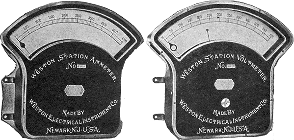
Figs. 651 and 652.--Weston illuminated dial station voltmeter and ammeter. The voltmeter has two indices, a pointed index for close readings and an index called the normal index, which enables a slight deviation from the normal voltage to be seen from a long distance. The "normal index" is inside the case and terminates in a circular disc of blackened aluminum. The disc is adjusted from the outside of the case by hand, by means of the knurled knob seen on the front of the case, so that it is directly below the point of normal voltage. When the indicating index reaches the point of normal voltage, the disc of the normal index appears in the center of the circular opening of the indicating index, a narrow ring of white being visible, encircling the disc of the normal index. The ammeter depends for its operation upon the fall of potential between two points of the circuit carrying the main current, and requires a difference of only about .05 volt to give a full scale deflection. When a maximum deflection is secured, the current passing through the instrument is never more than .07 ampere irrespective of the total capacity of the instrument. A separate shunt is used which is placed at the back of the switchboard. In many cases, a special shunt can be dispensed with and a short section of the mains on the switchboard, or the mains leading from the dynamo, can be used instead. On the basis of one square inch cross section per 1,000 amperes, a length of about 5 feet of copper conductor would be required as a shunt, in which case however, this section of the conductor must be adjusted with precision.
Ques. Explain the operation of the Siemen's electrodynamometer.
Ans. In fig. 646, when a current is passed through both coils, the movable coil is deflected against a stop pin, then the screw D is turned in a direction to oppose the action of the current until the deflection has been overcome and the coil brought back to its original position. The angle through which the pointer of the torsion screw was turned is directly proportional to the square root of the angle of torsion. To determine the current strength [559] in amperes, the square root of the angle of torsion is multiplied by a calculated constant furnished by the makers of this instrument.
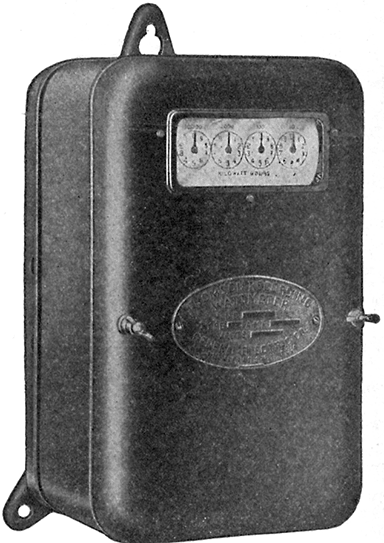
Fig. 653.--Thompson watt hour meter (type C-6). This form is furnished with side connections, the line wires entering at the left and the load wires at the right. Both sides of the system are carried through the meter in all sizes up to and including the 50 ampere size. In meters of larger ampere capacities, a voltage tap is used.
Ques. How is the electrodynamometer adapted to measure volts or watts?
Ans. When constructed as a voltmeter, both coils are wound with a large number of turns of fine wire making the instrument sensitive to small currents. Then by connecting a high resistance in series with the instrument it can be connected across the terminals of a circuit whose voltage is to be measured. When constructed as a wattmeter, one coil is wound so as to carry the main [560] current, and the other made with many turns of fine wire of high resistance suitable for connecting across the circuit. With this arrangement, the force between the two coils will be proportional to the product of amperes by volts, hence, the instrument will measure watts.
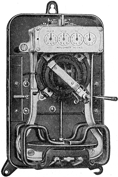
Fig. 654.--Interior view of Thompson watt hour meter (type C-6). Capacity: 5 to 600 amperes, two wire, and 5 to 300 amperes, three wire; 100 to 250 volts. The meter is supported by three lugs, the upper one of which is keyholed, and the lower right hand one slotted. This permits rapid and accurate levelling as the top screw can be inserted and the meter hung thereon approximately level. The right hand screw may then be placed in position and the meter adjusted as may be required before forcing the screw home.
Ques. Describe briefly the construction of the Thompson recording wattmeter.
Ans. It consists of four elements: 1, a motor causing rotation; 2, a dynamo providing the necessary load or drag; 3, a registering device, the function of which is to integrate the instantaneous values of the electrical energy to be measured; and 4, means of regulation for light and full load.
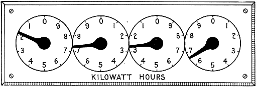
HOW TO READ A METER
Fig. 655.--Recording dials of watt hour meter, illustrating method of reading electric meters. The unit of measurement of electrical energy is the watt hour. 1,000 watt hours make or equal 1 kilowatt hour. Some electric meters have 4 dials, the extreme right hand dial of which registers in kilowatt hours, while others have 5 dials, the extreme right hand dial of which registers in tenths of kilowatt hours. In making out bills to customers the extreme right hand dial of a 5 dial meter is ignored in order that the "state of meter" shown on bills uniformly requires the addition of 3 ciphers to correctly express the registration in watt hours. Each division on the right hand dial (ignoring the 5th dial mentioned) denotes 1,000 watt hours or 1 kilowatt hour; on the next dial 10 kilowatt hours, on the next dial 100 kilowatt hours and on the left hand dial 1,000 kilowatt hours. One complete revolution of any dial causes the hand on the dial immediately to its left to move forward one division. To take a statement from the meter begin at the left and set down for each dial the lower figure next to each hand, not necessarily the figure nearer the hand. In the above example the statement is 1,726 kilowatt hours or 1,726,000 watt hours. Subtract the previous statement to arrive at registration for a given period. Some meters are subject to a multiplying constant so stated on their face and the registration of such meters must be multiplied by the constant as shown, to determine the actual consumption of electrical energy. The constant is the measure of the mechanical adjustment in the register of the meter and is the ratio between the registration of the dial hands and the true consumption. This adjustment is made always by the manufacturer of the meter and is never changed in service.
[562] Ques. What is the action of the motor in the Thompson watt hour meter?
Ans. It rotates at very slow speed, and since there is no iron in its fields and armature, it has very little reverse voltage. Its armature current, therefore, is independent of the speed of rotation, and is constant for any definite voltage applied at its terminals.
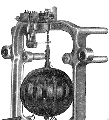
Fig. 656.--Interior of Thompson watt hour meter (type C-6) showing armature, small commutator and gravity brushes. A spherical armature moving within circular field coils is the construction adopted in this meter. The armature is wound on a very thin paper shell, stiff enough to withstand the strain due to winding and subsequent handling. The wire composing the armature is of the smallest gauge consistent with mechanical strength. The field coils, as before stated, are circular, and are placed as near each other as possible, one on either side of the armature, with the internal diameter just sufficient to give the necessary clearance for the rotating element. This construction prevents magnetic leakage. Ribbon wire is employed for the field coils, thus economizing space and further carrying out the idea of concentration.
The torque of this motor being proportioned to the product of its armature and field currents, must vary directly as the energy passing through its coils. In order then, that the motor shall record correctly it is necessary only to provide some means for making the speed proportional to the torque. This is accomplished by applying a load or drag, the strength of which varies directly as the speed.
[563] Ques. Explain the operation of the Thompson recording wattmeter.
Ans. There being no iron in either field or armature of the motor element, no considerations of saturation are involved. The torque or pull of the armature is dependent upon the product of the field and armature strength. The strength of the field--there being no iron--varies directly with the current in the field. Thus the strength of the field with 10 amperes flowing to the load is exactly twice the strength of the field with 5 amperes flowing to the load. The strength of the armature is dependent on the voltage of the system to which it is connected, the armature element of the meter being practically a voltmeter. There is, therefore, a torque or pull varying directly with the strength of the armature multiplied by the strength of the field, or, in other words, varying directly with the watt load, and except in so far as influenced by friction, the speed of rotation varies directly with the torque or pull. The currents generated in the disc armature consist of eddy currents, which circulate within the mass of the disc.
Installation of Wattmeters.--The various types of wattmeter differ so widely either in mechanical details, or operating principles, that it is customary for manufacturers to furnish detailed instructions for the installation of their meters. Such instructions should be carefully followed in all cases, but the following will be found generally applicable to all types of motor meter:
[B] NOTE.--The most practical and accurate method of plumbing a meter is to level it by means of a small brass weight placed upon the retarding disc. Place the weight upon the front or back upper surface of the disc, close to the edge. If the disc and weight rotate toward the right, move the bottom of the meter in the same direction so as to raise the disc on the right. When the disc is level, the weight and disc will remain stationary when the weight is placed on either the front or the back of the disc. Next, place the weight on the disc close to the edge on either side. If the disc rotate towards the front, swing the bottom of the meter away from the wall or board until the disc remains stationary when the weight is placed upon it on either side. If the disc rotate toward the back, raise it up on that side by bringing the top of the meter away from the wall or board. It is possible that the second levelling operation will alter the position of the disc obtained by the first operation, therefore, the first should be repeated, and after that the second also, until the disc remains stationary when the weight is placed at any point upon its surface. This method of levelling is more reliable than any method in which a spirit level is employed.
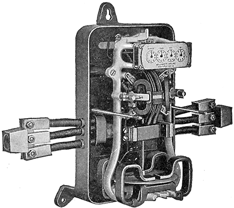
Fig. 657.--Interior view of Thompson watt hour meter (type CQ). The capacities of this type range from 50 to 400 amperes inclusive, two wire, and 50 to 200 amperes inclusive, three wire, and for voltages of from 100 to 600 volts. These meters are made with either front or back connections. In front connected meters the positions of the leading-in wires and cables are the same as in the type C-6, fig. 654, so that either type of meter may be installed in the same location.
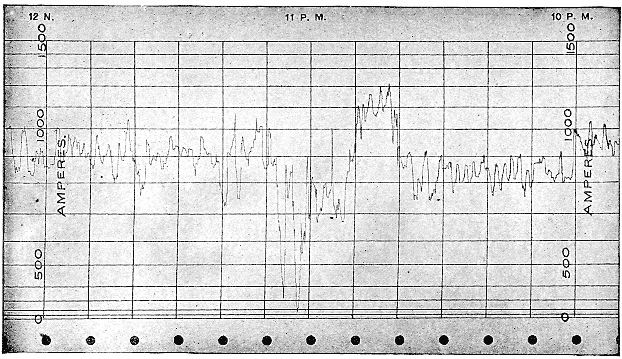
Fig. 658.--Specimen record from General Electric recording ammeter. The record is made on a band of specially prepared paper four inches wide and sixty feet in length. On this paper are ruled lines corresponding to time, and the instrument calibration. The lines ruled across the paper represent time; those ruled lengthwise represent volts, amperes, or watts, depending upon the instrument construction. This form of paper has the advantage of permitting the use of time divisions of equal length throughout the entire range of the recording pen. The recording pen is attached to the moving element in such a manner that its motion is transmitted in a straight line parallel to the time division on the chart. As the paper is unwound and passed under the recording pen, it is paid into a space at the bottom of the instrument case. To assist in removing paper, the instrument is provided with a stripper, which enables the paper to be torn off evenly and without damage. The paper feeding mechanism is simple. By means of suitable gearing, the clock drives a drum having peg teeth which engage the holes located near the edge of the paper. These teeth not only feed the paper under the recording pen, but also give it a definite and accurate position along the axis of the drum. The feeding drum is driven by a friction clutch.
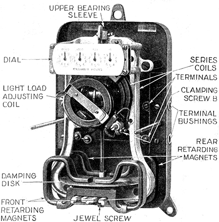
Fig. 659.--Westinghouse type CW-6 watt hour meter with cover off. This meter is of the commutator type without iron in the magnetic circuit. The spherical armature is closely surrounded by circular field coils which provide the shortest magnetic path and smallest magnetic leakage, thus securing high torque with small consumption of energy. The armature winding is wound on a hollow sphere of prepared paper which is moulded in corrugated form to secure strength. Uniform brush tension is maintained by gravity. Each brush consists of two small round wires placed side by side and held against the commutator by a small counterweight whose distance from the fulcrum is adjustable. The current winding consists of two flat coils of strap copper, one clamped rigidly on either side of the central mounting frame which supports the armature bearings. These coils are connected either in series or parallel, depending on the capacity. In three wire meters one of the coils is connected in series with each side of the line. The retarding element consists of a light aluminum disc rotating between two pairs of permanent magnets. The magnets are prepared by a special aging process to insure permanence. Full load adjustment is made by shifting the position of the permanent magnets. Ample light load adjustment or friction compensation is provided by means of the movable coil, which can be shifted horizontally or radially on loosening one screw. The meter registers directly in kilowatt hours.
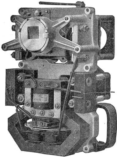
Fig. 660.--Interior of Thompson prepayment watt hour meter. The actuating force is a large flat coil spring enclosed in a barrel or drum to which its outside end is attached. The operating knob winds this main spring by turning the drum. The spring has many turns and as the operation of the device never equals one whole turn, the spring always exerts a practically constant force. The rate device consists of a small train of gears secured to the front of the frame directly back of the register. Each device is marked with the price per kw-hr. for which it should be used. The switch is of the double pole double break type with leaf contacts. The coin receptacles are placed at the back of the meter. To make an advance payment, the winding knob is turned so that the arrow points upward. A quarter dollar is then inserted in the slot and the knob turned to the right, the coin serving as a key which operates the mechanism within the device, turning the registering wheel and placing the coin to the credit of the customer. If the circuit be open when the coin is deposited the same motion of the knob which moves the registering mechanism closes the circuit switch contained within the case. The dial contains a scale marked in plain figures over which a pointer passes indicating the number of coins remaining to the credit of the depositor. When the first coin is deposited and the knob turned closing the main switch, the pointer rests opposite the first division on the scale. If a second coin be deposited before the current purchased with the first coin has been consumed, a second motion of the knob will bring the pointer opposite the second division on the scale. Twelve coins can thus be deposited consecutively, after which the slot is automatically closed and further prepayment cannot be made until the value of one or more coins has been consumed. Whenever energy to the value of one coin has been delivered through the meter, the escapement is mechanically released turning the pointer back one division. This process continues until all the energy has been delivered for which payment has been made. Thus the depositor can ascertain at any time how much energy can be obtained without further payment. When all energy has been delivered, the circuit switch is opened so that no more current can be obtained until one or more coins have been deposited. The indicating mechanism shows only the number of coins which stand to the credit of the customer, but, by consulting the meter dial, one can determine what fractional part of the prepayment next to be cancelled remains to the credit of the customer. A coin or washer larger than the coin for which the device is designed cannot be introduced into the receiving slot and a smaller one will not operate the device.
How to test a meter.--A simple test for ascertaining whether a customer's meter is fast or slowC, may be applied as follows:
The difference between the first and second readings of the dial will be the indicated consumption of two hours, and if this be greater than the amount of power that ought to be consumed by the number of lamps turned on, the meter is fast, but if it be less, the meter is slow.
The best results obtained by this method are only approximations, however, on account of the variations in the watts consumed by the different makes of lamp, the uncertainty as to the actual voltage on the line at the time of the test, and the lack of knowledge as to the age of the lamps. Therefore, if the meter test within five per cent., or do not record more nor less than one-twentieth of the assumed lamp consumption it is safe to assume that the meter is correct as the result of the test is not likely to be any closer to the truth.
[C] NOTE.--A meter operates under more varied and exacting conditions than almost any other piece of apparatus. It is frequently subjected to vibration, moisture and extremes of temperature; it must register accurately on varying voltages and various wave forms; it must operate for many months without any supervision or attention whatever; and, in spite of all these conditions, it is expected to register with accuracy from a few per cent. of its rated capacity to a 50 per cent. overload. As a meter is a type of machine, its natural tendency is to run slow; but occasionally, through accident, a meter may run fast. When a meter runs fast the consumer is paying a higher rate per kilowatt hour than his contract calls for. He is being discriminated against. The periodic testing of meters is therefore a necessity and is an indication of the honesty of intention of the manager toward the customers of his company. Meters controlling a very large amount of revenue may be tested as often as once a month, while the ordinary run of meters should be tested at least once a year, once in eighteen months, or once in two years, the period varying with different companies, different types and different civic requirements. Commutator type meters, having comparatively heavy moving elements with consequent rapid increase in friction due to wear on the jewel and bearings, and a commutator also increasing in friction with age, must have frequent and expert attention to insure their accuracy under all conditions.
Ques. How should a roughened commutator be cleaned and smoothed?
Ans. By means of tape.
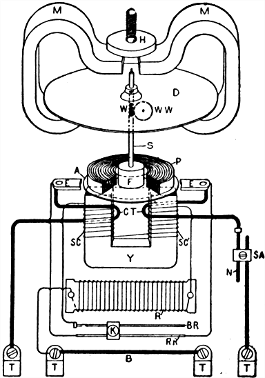
Fig. 661.--Internal connections of Sangamo watt hour meter (type D). A, copper disc armature, submerged in mercury; B, bridge wire between binding posts, for main load current, when both sides of the line are carried through the meter; CT, compounding series turns around pressure circuit magnet, building up field as load increases, to compensate for falling off in speed otherwise found; D, aluminum damping, or brake disc, controlling speed of meter; E, copper contact ears, imbedded in insulating wall of mercury chamber, leading current into and out from armature; F, hardwood float on armature proportioned to give slight "lift" to entire moving system, when armature and float are immersed in mercury; H, soft steel disc above permanent magnets, riveted to fine pitch screw working in bracket above, so that adjustment of the disc up or down gives variation in damping effect of permanent magnets, and therefore of main speed. K, clamp slider with thumb screw, for obtaining light load adjustment by moving K to right or left, as may be necessary. K spans and connects parallel wires of light load adjustment, BR and RR'. MM, powerful permanent magnets, acting on disc D, giving main speed control for meter. N, high resistance heavy wire, forming part of series adjustment between armature and any shunt with which meter may be used, to set drop through meter correct for drop of the shunt. P, spirally laminated soft steel ring, moulded in mercury chamber above the armature space, to act as a return for magnetic lines of force from and to energizing magnet below. R, resistance card unit, in series with pressure circuit coils; in 110 volt meters one card is used, in 220 volt meters two cards, or one card and a thermocouple. BR, small brass wire, connected to ingoing end of pressure circuit coils and forming RR' and the slides K the light load adjustment. RR', high resistance wire having opposite ends connected to ears EE by low resistance wires. Current energizing the pressure circuit coils SC passes from RR' through K to BR and thence to the coils, and if K be near the end of RR' and BR, the least compensation is obtained; if near right end, maximum light load compensation is obtained. S, shaft or spindle. In actual meter S is divided, the lower shaft carrying armature A, and the upper shaft damping disc D. SA, series resistance adjustment, for setting meter to correct drop for shunt. SC and SC', pressure coils connected in series. TT, binding posts at bottom of meter. Y, laminated soft steel yoke, carrying coils SC and SC', and giving a powerful and concentrated magnetic field on the armature. W, worm, driving recording dial train. WW, worm wheel.
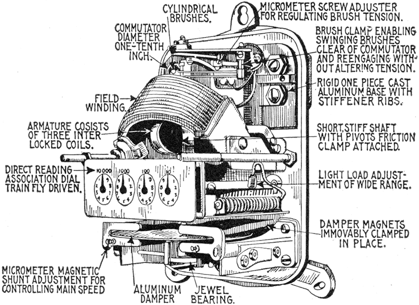
Fig. 662.--Interior view of Columbia watt hour meter (type D), showing construction and principal parts and connections. The armature winding consists of three coils approximately circular in shape. The coils are form wound, interlocked with one another and with the light impregnated fibre disc which serves as a spacer for them. The aluminum damper disc has the conventional anti-creep provision in the shape of the three small soft iron plugs, mounted close to the central staff, which the illustration shows. These in their revolution come successively within the influence of an adjustable iron screw which is magnetized by an extension from one of the damper magnets. The angular relationship of the armature windings and of the three iron plugs is such that at the time that the armature is exerting a maximum torque the magnetized screw is exerting the maximum pull to hold back a given plug and conversely when the armature pull is a minimum the magnetic screw is attracting a plug with the maximum effort to cause ahead rotation. The irregularities of torque are in this way smoothed out. The commutator has three segments and is made of chemically pure silver. Each brush is formed of a length of phosphor bronze wire bent like a hair pin and secured at its "U" end to a brass sleeve, which in turn is secured to an insulated stud by a set screw. An extension on the sleeve carries a micrometer screw brush adjustment. The main speed adjustment is secured by providing a soft iron bridge plate, bridging over the extremities of each magnet end and adjustable, by means of a set screw and lock nut, to any desired distance therefrom. This gives a regular micrometer means of varying the effective magnet strength. Interposed between the series coil and the permanent magnets is a heavy soft iron shield to guard the magnets against disturbance by short circuiting. Light load adjustment is obtained by providing in the coil circuit a series of small resistance spools, equipped with pin terminals, to which connection can be selectively made by means of a split bushing terminal on a flexible cord. This series of spools is strung on a metal arbor located within the case.
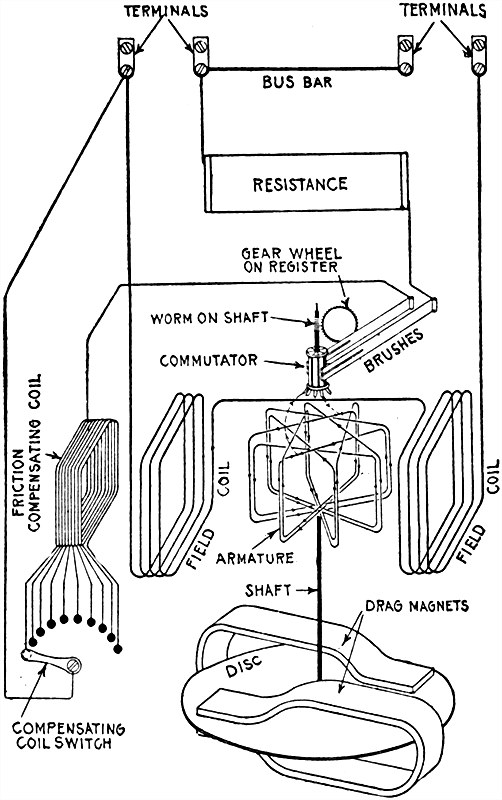
Fig. 663.--Diagram showing internal connections of the Duncan watt hour meter. Its operation depends upon the principle of the well known electro-dynamometer, in which the electromagnetic action between the currents in the field coils and an armature produces motion in the latter. It also embodies the other two necessary watt hour meter elements required for the speed control and registration of the revolutions of the armature, these being embodied in the drag magnet and disc, and the meter register respectively. The motion of the armature is converted into continuous rotation by the aid of a commutator and brushes, the commutator being connected to the armature coils and carried on the same spindle therewith.
[572] Waste of Electricity in Lighting.--In large residences where a good many servants are employed or in any place where the power consumed is not directly under the supervision of the person who must pay the bills, a great deal of waste usually occurs.
If the meter be read before retiring, the reading in the morning will show how much energy was consumed during the night, which will show in turn how many lamps were burning all night.
A great deal of light can be saved by placing the lamps so that they will throw the light where it is needed and by placing small lamps such as 8 candle power and 4 candle power in places where not much light is needed, such as bathrooms, halls, cellars, etc.
When the lamps get old and dim they should be replaced with new ones, as it costs about the same to burn an old lamp as a new one. An old 16 candle power lamp which is very dim will give only about 8 candle power and use about as much current as is required for a new 16 candle power. If the dim light be light enough, it should be replaced by an 8 candle power lamp, which will not consume as much power as the old 16 candle power.
Before Starting a Dynamo or Motor.--When the machine has been securely fixed, it should be carefully examined to see that all parts are in good order. The examination should be made as follows:
In the subsequent working of the dynamo it will of course be unnecessary to follow the whole of these proceedings every time the machine is started, as it is extremely unlikely that the machine will be damaged from external causes while working without the attendant being aware of the fact.
Adjusting the Brushes.--The adjustment of the brushes upon the commutator requires careful attention if sparking is to be avoided. There are two adjustments to be made:
Ques. At what point on the commutator should the brushes bear?
Ans. The points upon the commutator at which the tips of the brushes (carried by opposite arms of the rocker) bear, should [575] be, in bipolar dynamos, at opposite extremities of a diameter. In multipolar dynamos the positions vary with the number of poles and the nature of the armature winding.
Ques. What provision is made to facilitate the correct setting of the brushes?
Ans. Setting marks are usually cut in the collar of the commutator next to the bearing.
Figs. 664 and 665.--Diagrams illustrating how to set brushes. Some brush holders require brushes set with the direction of rotation of the commutator, and others, set against the direction of rotation. In fig. 664 is shown a brush holder of the first class, which must always be set as indicated by the arrow. If set in the opposite direction, trouble will ensue, as an inspection of the figure will show, because the surface of the commutator and the brush would form a toggle joint, and the brush would tend to dig into the commutator and either break itself or bend the brush rigging. In fig. 665 is shown a brush holder of the second type. This brush is set against the direction of rotation, but an inspection of the cut will show that there is, in this case, no tendency for the brush to dig into the commutator surface. Each type of brush holder, of which there are several, should be adjusted as recommended by the manufacturer to secure proper working.
Ques. How are the brushes set by these marks?
Ans. The tips of all the brushes carried by one arm of the rocker are set in correct line with the commutator segments marked out by one setting mark, and the tips of the brushes carried by the other arm or arms are set in correct line with the segments marked out by the other mark or marks.
If one or more of the brushes in a set be out of line with their setting mark, it will be necessary to adjust the brushes up to this mark by pushing them out or drawing them back, as may be required, afterwards [576] clamping them in position. When adjusting the brushes, the armature should always be rotated, so that the setting marks are horizontal. The rocker can then be rotated into position, and the tips of both sets of brushes conveniently adjusted to their marks. In those brush holders provided with an index or pointer for adjusting the brushes, the setting marks upon the commutator are absent, length of the pointer being so proportioned that when the tips of the brushes are in line with the extreme tips of the pointers, the brushes bear upon the correct positions on the commutator.
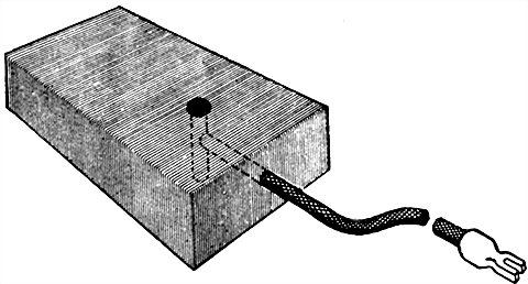
Fig. 666.--Method of soldering cable to carbon brush. Drill a hole in the end, also in the side of the brush, as shown in the sketch, and after thoroughly tinning the "pig-tail," place it in the end hole and fill the holes up with solder through the side hole. Another method is to drill a hole through the carbon so that the cable will just slip through, countersink the edge of the hole a little, clean the cable thoroughly and pass it through the hole. Then with any good flux and solder, fill the countersunk part on both sides.
Ques. What should be done after adjusting the brushes to their correct positions upon the commutator?
Ans. Their tips or rubbing ends should be examined while in position to see that they bed accurately on the surface of the commutator.
In many instances it will be found that this is not the case, the brushes sometimes bearing upon the point or toe, and sometimes upon the heel, so that they do not make contact with the commutator throughout their entire thickness and width. The angle of the rubbing ends will therefore need to be altered by filing to make them lie flat.
[577] Ques. How is the proper brush contact secured?
Ans. When the brushes do not bed properly they should be refitted to secure proper contact.
Ques. How is the pressure adjustment made?
Ans. This is effected by regulating the tension of the springs provided for the purpose upon the brush holders.
Ques. With what pressure should the brushes bear against the commutator?
Ans. The tension of the springs should be just sufficient to cause the brushes to make a light yet reliable contact with the commutator.
The contact must not be too light, otherwise the brushes will vibrate, and thus cause sparking; nor must it be too heavy, or they will press too hard upon the commutator, grinding, scoring and wearing away the latter and themselves to an undesirable extent, and moreover, giving rise to heating and sparking.
The correct pressure is attained when the brushes collect the full current without sparking, while their pressure upon the commutator is just sufficient to overcome ordinary vibration due to the rotation of the commutator.
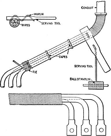
Figs. 667 to 669.--Method of winding cables with marlin. When connecting the feeders and dynamo and service leads to a switchboard, the wires are often served with marlin. By serving is meant to tightly wrap the wires of each set together with marlin. A tool for serving may be made as in fig. 667, using a piece of oak 2 ins. wide, 7/8 in. thick and 14 ins. long, having four holes drilled through it, as shown. The marlin is passed through the holes, commencing at the hole nearest the handle, the object being to cause a strain on the marlin at the point where it passes around the wire, so that the marlin may be wrapped tightly. It is necessary to serve the first four or five inches by hand, pushing the winding into the conduit as far as possible. This acts as an additional protection to the wires where they leave the conduit. The serving is continued, as in fig. 668, to within four or five inches of the first lug by means of the serving tool, passing the ball of marlin around the wires with the serving tool. The wires are then bent in shape, as in fig. 669. To serve the wires properly it is necessary to tie the ends of the wires taut. The wires should be straightened and run together so as to be parallel, being bound with tape at different points to keep them so. When the serving is complete the marlin should be thoroughly painted with a moisture resisting compound. The marlin serving will stiffen the wires and they can be bent very neatly to avoid touching the bus bars of the board. When painted the marlin hardens so that it is difficult to bend the wires after the paint has dried. It then requires a strong pressure to bend them. The marlin acts as an additional insulation and mechanical protection to the wires, and while no harm would result from the wires coming in contact with the bars while thus protected, it looks better to bend them so as to avoid touching the bars.
Direction of Rotation.--This is sometimes a matter of doubt and often results in considerable trouble. As a general rule, a dynamo is intended to run in a certain direction; either right handed or left handed according to whether the armature, when looked at from the pulley end, revolves with or against the direction of the hands of a clock. Dynamos are usually designed to run right handed, but the manufacturers will make them left handed if so desired.
It may be necessary to reverse the direction of rotation of a dynamo, if the driving pulley to which it has to be connected happen to revolve left handed, or if it be necessary to bring the loose side of the belt on top of the pulley, or to place the machine [579] in a certain position on account of limited space. The direction of rotation of ordinary series, shunt, or compound bipolar dynamos may be reversed by simply reversing the brushes without changing any of the connections, then changing the point of contact of the brush tips 180°.
In multipolar dynamos, a similar change, amounting to 90° for a four pole machine, and 45° for an eight pole machine, will reverse their direction of rotation. It will be understood that under these conditions, the original direction of the current and the polarity of the field magnets will remain unchanged.
This rule does not apply to arc dynamos and other machines, which have to be run in a certain direction only, in order to suit their regulating devices.
If the direction of current generated by a dynamo be opposite to that desired, the two leads should be reversed in the terminals, or the residual magnetism should be reversed by a current from an outside source.
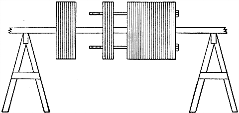
Fig. 670.--Method of assembling core discs. For this operation two wooden "horses" should be provided to support the core at a convenient height, as shown in the illustration.
[580] Starting a Dynamo.--Having followed the foregoing instructions, all keys, spanners, bolts, etc., should be removed from the immediate neighborhood of the machine, and the dynamo started.
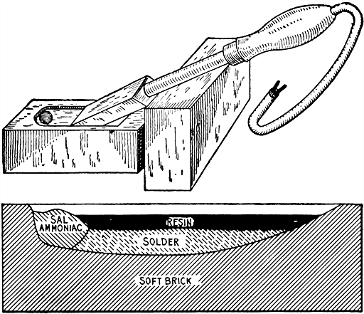
Figs. 671 and 672.--Tinning block for electric soldering tool. It is made with two soft bricks. One brick is used to support the soldering tool, and the other to contain the tinning material and to furnish a material which will keep the copper bit bright enough to receive its coating of "tin." Fig. 671 represents a section of the tinning brick, which is scooped out on top as shown by the lower line. Into one end of the hollow in the brick, some sal-ammoniac is placed to help tin the copper bit. Sal-ammoniac is a natural flux for copper and aids greatly in keeping the tool well tinned. Next, some melted solder is run into the hollow of the brick, and lastly enough resin to fill the cavity nearly to the top. When the tool is not in use, the electricity is switched off and the tool permitted to lie in the resin. If it be desired to repair the tin coating a little when the tool is in use, the latter is rubbed on the brick below the layer of solder, and the layer of resin. If the tool be in very bad condition, it may be pushed into the sal-ammoniac once or twice and then rubbed in the solder again. It requires but little heat to keep the brick and its contents ready for use. In fact, the brick is a fair non-conductor of heat and prevents the escape of heat from one side of the tool. When momentarily not in use, the tool remains in the solder which becomes melted underneath the layer of resin. When the copper bit becomes too hot, it will begin to volatilize the resin, thus calling attention to this fact, whereupon, the electricity should be turned off from the tool.
[581] Ques. How should a dynamo be started?
Ans. A dynamo is usually brought up to speed either by starting the driving engine, or by connecting the dynamo to a source of power already in motion. In the first case, it should be done by a competent engineer, and in the second case by a person experienced in putting on friction clutches to revolving shafts, or in slipping on belting to moving pulleys.
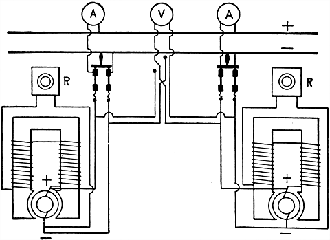
Fig. 673.--Connections for two shunt wound dynamos to run in parallel. The positive lead of each machine is connected to the same bus bar. In starting, if but one machine is to be used, the dynamo is first brought up to speed and the voltage regulated by means of the rheostat R and the voltmeter V. The main switch is then thrown in. The connections for the field are taken off the dynamo leads so that the opening of the main switch will not open the field circuit and for this reason the field will begin to build up as soon as the machine is started. When but one of the machines is running, the idle machine is brought up to speed with the main switch open, and the voltage regulated by means of the rheostat and voltmeter until the voltages of the machines are the same. Then the main switch is thrown in and the load on the machines (which is ascertained by the ammeters) is equalized by means of the rheostats. Should there be any great difference in voltages, the higher one will run the other as a motor without changing the direction of rotation. The field current will remain unchanged, and the armature current of the low dynamo will be reversed, which will cause it to run as a motor in the same direction as it ran as a dynamo. When dynamos feeding current to motors are to be shut down, the switches on the motors should first be opened. Otherwise some of the motor fuses will blow. As the voltage goes down the motors will draw more current to do the work. If a plant be shut down with the motor switches "in" it will generally be found impossible to start a shunt dynamo, the low resistance in the mains not allowing enough current to flow around the shunt fields to energize them.
[582] Ques. Should the brushes be raised out of contact in starting?
Ans. The brushes should not be in contact in starting if there be any danger of reverse rotation, as might happen when the dynamo is driven by a gas engine. Aside from this, it is desirable that the brushes be in contact, because they are more easily and better adjusted, and the voltage will come up slowly, so that any fault or difficulty will develop gradually and can be corrected, or the machine stopped before any injury is done.
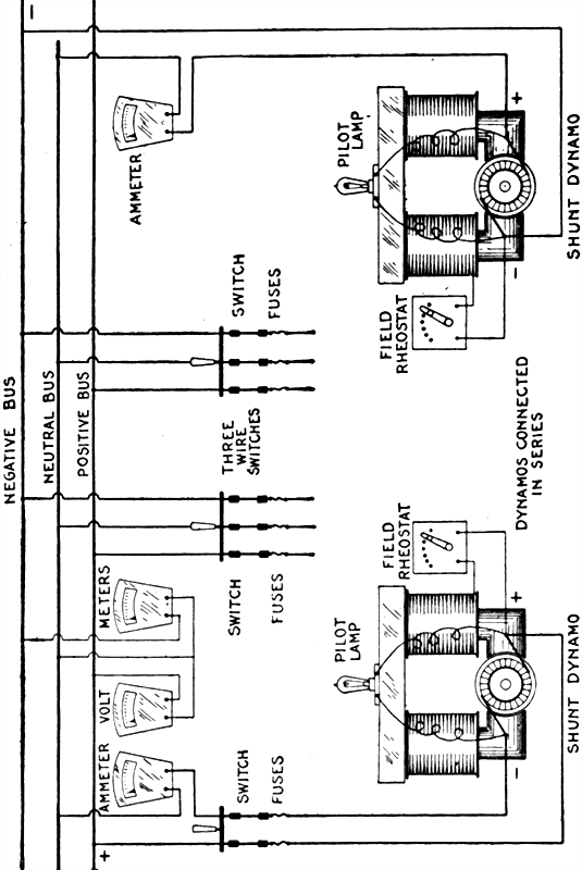
Fig. 674.--Connections for two shunt dynamos to run on the three wire system. The two machines are connected in series, three wires being carried from them, one from the outside pole of each machine and one from the junction of the two machines. The voltage between the outside wires is equal to the combined voltage of the two machines and the voltage between the outside and the central or neutral wire is equal to the voltage of the corresponding machine. If the load on each side of the system be equal, there will be no current in the neutral wire, while if the loads be unequal, the neutral wire will have to carry the difference in current between the two outside wires.
Ques. How should a series machine be started?
Ans. The external circuit should be closed, otherwise a [583] closed circuit will not be formed through the field magnet winding and the machine will not build up.
Ques. What is understood by the term "build up"?
Ans. In starting, the gradual voltage increase to maximum.
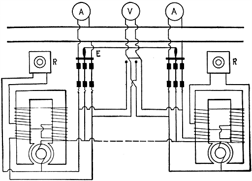
Fig. 675.--Connections for two compound wound dynamos to run in parallel. The series fields of the machines are connected together in parallel by means of wire leads or bus bars, which connect together the brushes from which the series fields are taken. This is known as the equalizer and is shown by the line running to the middle pole of the dynamo switch. By tracing out the series circuits it will be seen that current from the upper brush of either dynamo has two connections to its bus bar. One of these leads through its own field, and the other, by means of the equalizer bar, through the fields of the other dynamo. As long as both machines are generating equally there is no difference of pressure between the brushes of either, but should the voltage of one be lowered, current from the other would flow through its fields and thereby raise the voltage, and at the same time reduce its own until both are equal. The equalizer may then be called upon to carry much current, but to have the machines regulate closely it should be of low resistance. It may also be run as shown by the dotted lines, but this will leave all the machines alive when any one is generating. The ammeters should be connected as shown. If they were on the other side they would come under the influence of the equalizing current and would indicate wrong, either too high or too low. The equalizer switch should be closed a little before the main switches are closed.
Ques. How should a shunt or compound machine be started?
Ans. All switches controlling the external circuits should be opened, as the machine excites best when this is the case. If [584] the machine be provided with a rheostat or hand regulator and resistance coils, these latter should all be cut out of circuit, or short circuited, until the machine excites, when they can be gradually cut in as the voltage rises.
When the machine is giving the correct voltage, as indicated by the voltmeter or pilot lamp, the machine may be switched into connection with the external or working circuits.
Ques. In starting a shunt dynamo, should the main line switch be closed before the machine is up to voltage or after?
Ans. If the machine be working on the same circuit with other machines, or with a storage battery, it is, or course, necessary to make the voltage of the machine equal to that on the line before connecting it in the circuit. If the machine work alone, the switch may be closed either before or after the voltage comes up. The load will be thrown on suddenly if the switch be closed after the machine has built up its voltage, thus causing a strain on the belt, and possibly drawing water over the engine cylinder. On the other hand, if the switch be closed before the voltage of the machine has come up, the load is picked up gradually, but the machine may be slow or may even refuse to pick up at all.
Ques. Why does a shunt machine pick up more slowly if the main switch be closed first?
Ans. Because the resistance of the main line is so much less than that of the field that the small initial voltage due to the residual magnetism causes a much larger current in the armature than in the shunt field. If this be too large, the cross and back magnetizing force of the armature weakens the field more than the initial field current strengthens it, and so the machine cannot build up.
[585] Ques. If a shunt dynamo will not pick up, what is likely to be the trouble?
Ans. The speed may be too slow; the resistance of the external circuit may be too small; the brushes may not be in proper position; some of the electrical connections in the dynamo may be loose, broken or improperly made; the field may have lost its residual magnetism.
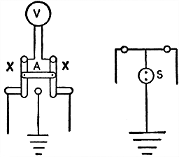
Figs. 676 and 677.--Diagrams of ground detectors. Fig. 676, a ground detector switch suitable for mounting on a switch board. The two arms pivoted at their upper ends are connected with an insulating bar A and make contact at their lower ends with two brass strips and a contact button, which are connected to the bus bars and ground, respectively. When the arms are moved to the left, the positive bus bar is connected to the ground through the voltmeter V. In fig. 677 is another form of ground detector. This is known as a lamp ground detector. On a 110 volt system two ordinary lamps are connected in series, while the line connecting the lamps is connected to the ground through a snap switch S. When current is on, the two lamps will burn with equal brilliancy, but at a lower candle power. When the switch S is closed, if the two lines be clear, the brilliancy of the lamps will not be affected, but if there be a ground on the positive side, one lamp will burn brighter, the brightness depending on the resistance of the ground. If there be a dead ground, the lamp will burn to its full candle power.
Ques. What is the indication that the connections between the field coils and armature are reversed?
Ans. If the machine build up when brought to full speed, the connections are correct, but if it fail to build up, the field coils may be improperly connected.
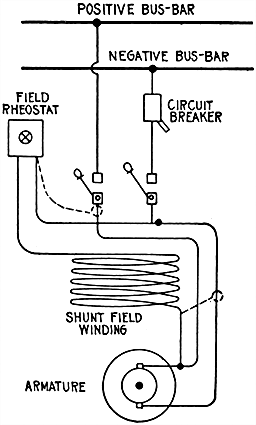
Fig. 678.--Method of correcting reversed polarity in large shunt dynamo by transposing the shunt field leads, and then starting up the machine. As soon as the voltmeter registers any voltage, the dynamo may be stopped and the field leads restored to their original position, when it will be found that the residual magnetism in the pole pieces will usually bring the dynamo up to its polarity and proper voltage. This method has the disadvantages, of the uncertainty as to the machine building up, and that a temporary wire must probably be run from the switchboard to one terminal of the field circuit, which is usually connected to a terminal back of the dynamo frame, so that the flow of current through the field coils may be reversed. With dynamos having laminated field magnet cores of comparatively low residual magnetism, this method may suffice, but in the case of solid field magnetic cores it is not practical. A better method is to disconnect the shunt field leads and temporarily extend them to some other source of direct current. If the current be of higher voltage than the coils are designed for, as for instance 110 volt dynamo and available current 500 volt, caution must be exercised and a suitable resistance be provided to protect the coils. A 500 volt coil, however, may be supplied from 110 volt circuit, providing the field winding to be energized is equipped with a cut off switch having a discharge resistance, so that it may be used to close and break the circuit when the temporary leads have been connected. If the field windings be not so provided, a bank of lamps or some other non-inductive resistance must be connected across the leads between the field magnet coils and the point at which the circuit is to be opened and closed. This is to provide a path for the discharge of the induced electromotive force. The circuit should not remain closed more than a few seconds if the full voltage can be applied. It is well, however, to leave the current on long enough to run the machine up to about half speed and make sure, by means of a voltmeter, that the polarity has been corrected. When this has been ascertained the dynamo should be stopped and the field winding leads returned to their proper terminals. Then the voltage will be brought up in the right direction, provided the work has been done correctly.
[587] This can be tested by connecting a voltmeter across the terminals of the armature, or by means of a magnetic needle placed at a short distance from one of the pole pieces in such a position that it does not point to the north pole. If the field coils be improperly connected, the current due to the initial voltage will weaken the field magnetism and thus prevent the machine building up, and when the field circuit is closed the voltmeter reading will be reduced, or the magnetic needle will be less strongly attracted.
Ques. What will be the result if the connections of some of the field coils of a dynamo be reversed?
Ans. If one-half the number of coils oppose the other half, the field magnetism will be neutralized and the machine will not build up at all; but if one of the coils be opposed to the others, the machine might build up, but the generated voltage will be low, and there will be considerable sparking at some of the brushes.
Ques. How may it be ascertained which coil is reversed?
Ans. In all dynamos there should be an equal number of positive and negative poles, and in almost all of them the poles should be alternately positive and negative. Therefore, if a pocket compass be brought near the pole pieces, and it show that there are more poles of one kind than the other, the indication is that one or more of the coils are reversed, and the improper sequence of alternation will determine which one is wrongly connected.
Ques. When a dynamo loses its residual magnetism, how can it be made to build up?
Ans. By temporarily magnetizing the field. To do this a current is passed through it from another dynamo, or from the cells of a small primary battery. Usually, this will set up sufficient initial magnetism to allow the machine to build up. The battery circuit should be broken before the machine has built up to full voltage.
[588] Ques. What should be done if a dynamo become reversed by a reversal of its field magnetism due to lightning, short circuit, or otherwise?
Ans. The residual magnetism should be reversed by a current from another dynamo, or from a battery; but if this be not convenient, the connections between the machine and the line should be crossed so that the original positive terminal of the dynamo will be connected to the negative terminal of the line, and vice versa.
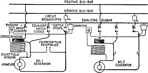
Fig. 679.--Method of correcting reversed polarity in compound wound dynamo. The polarity may be reversed without disconnecting or changing the wire. The figure shows two compound dynamos, and essential connections. The current from any machine connected to the equalizer bar by its equalizer switch will divide, a portion going through the series field winding of the other machines connected to the bus bar, the division being determined by the resistance of the different sets of coils. For instance, assume that No. 1 dynamo has had its polarity reversed and that No. 2 is running connected to the bus bar. The method of reversing the polarity of No. 1 machine is as follows: No. 1 machine should be at rest and then make sure that the circuit breaker and negative switch are open and that any other special connections to other machine or station lighting circuits are open. Then close the positive and equalizer switches, thus allowing a part of the current from the other dynamo to pass through the equalizer connection and through the series field winding of No. 1 machine in the usual direction, which will magnetize the magnetic core. If No. 1 machine be a large unit and No. 2 a small unit, it will be necessary to cut out the resistance of the shunt field circuits by means of the rheostat, if it be desired to maintain its bus bar voltage at its normal point. This will rob the series winding of any other machines which may be connected to the bus bars and will lower the voltage slightly. No. 1 machine is then brought up to full speed when it will be found to have recovered its correct polarity. The positive switch may be readily opened, watching the bus bar voltage closely as it will rise when the current is restricted again to the series field winding of the other machines. The dynamo will then be ready to cut in with the other machines as soon as the voltage has been brought up to the proper point, or it may be shut down until required.
[589] Ques. Can a dynamo be reversed by reversing the connections between the field coils and the armature?
Ans. No, for if these connections be reversed, the machine will not build up.
Ques. Will a dynamo build up if it become reversed?
Ans. Yes.
Ques. Then what is the objection to a reversed dynamo?
Ans. Since the direction of current of a reversed dynamo is also reversed, serious trouble may occur if it be attempted to connect it in parallel, with other machines not reversed.
Attention while Running.--When a dynamo is started and at work, it will need a certain amount of attention to keep it running in a satisfactory and efficient manner. The first point to be considered is the adjustment of the brushes. If this be neglected, the machine will probably spark badly, and the commutator and brushes will frequently require refitting to secure good contact.
Ques. What may be said with respect to the lead of the brushes?
Ans. The lead in all good dynamos is very small, and varies with the load and class of machine. The best lead to give to the brushes can in all cases be found by rotating the rocker and brushes in either direction to the right or left of the neutral plane until sparking commences, increasing with the movement. The position midway between these two points is the correct position for the brushes, for at this position the least sparking occurs, and it is at this position that the brushes should be fixed by clamping the rocker.
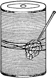
Fig. 680.--Method of taking temperature. In taking the temperature of a hot part, it is convenient to use a thermometer in which the scale of degrees has been etched on the stem. Bind this to the heated part, having first taken the precaution to cover the bulb with waste to prevent the radiation of heat and take the reading when the column of mercury has ceased to rise. The question which most often presents itself to the attendant is how hot can the various parts of a dynamo or motor become and yet be within the safe limit. The degree of heat can be determined by applying the hand to the various parts. If the heat be bearable it is entirely harmless, but if the heat become unbearable to the hand for more than a few seconds, the safety limit has been reached and the machine should be stopped and the fault located. Of course when the solder begins to melt at the commutator connections and shellac begins to "fry out" of the armature and an odor of burnt cotton begins to pervade the air, the safe limit has been far exceeded, and in most cases, as a matter of fact serious damage is the result. To be more definite, no part of the dynamo or motor should be allowed to rise in temperature more than 80 degrees F. above the temperature of the surrounding air, excepting in the case of commutators where no solder has been used to connect the leads. These can be allowed to rise to a still higher temperature.
Ques. How does the lead vary in the different types of dynamo?
Ans. In series dynamos giving a constant current, the brushes require practically no lead. In shunt and compound dynamos the lead varies with the load, and therefore the brushes must be rotated in the direction of rotation of the armature with an increase of load, and in the opposite direction with a decrease of load.
In cases where the dynamos are subjected to a rapidly varying or fluctuating load, it is of course not possible to constantly shift the brushes as the load varies, therefore the brushes should be fixed in the positions where the least sparking occurs at the moment of adjustment. [591] If at any time violent sparking occur, which cannot be reduced or suppressed by varying the position of the brushes by rotating the rocker, the machine should be shut down at once, otherwise the commutator and brushes are liable to be destroyed, or the armature burnt up. This especially refers to high tension machines.
Ques. What should be done if the brushes begin to spark excessively?
Ans. First, look at the ammeter to see if an excessive amount of current is being delivered; second, see if the brushes make good contact with the commutator, and if the latter have a bar too high, or too low, and an open circuit.
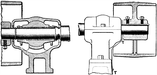
Figs. 681 and 682.--Remedies for leakage of oil from self-oiling bearings. If there be sufficient space, a metal ring may be attached to the shaft as in fig. 681. With this arrangement the high speed of the shaft will carry the oil outside of the ring and throw it off in the oil reservoir. Another way is to insert a tin apron, as shown in fig. 682 at T, which will serve to drain the oil which may creep along the shaft, and also cut off the draft from the pulley which may suck the oil out of the bearing. Sometimes a tin fan is attached to the pulley, which tends to drive the oil back into the bearing, and which also assists in keeping the box cool.
Ques. What should be done if the current be excessive?
Ans. If the current exceed the rated capacity by more than 50 per cent., and continue for more than a few minutes, the main switch should be opened, otherwise the machine may be seriously injured.
[592] Ques. How does an excessive current injure a dynamo?
Ans. By causing it to overheat which destroys the insulation of the armature, commutator, etc.
Lubrication.--The shaft bearings of dynamos may be lubricated by sight feed oilers or oil rings. The latter method is almost universally used. An oil well is provided in the hollow casting of the pedestals as shown in fig. 728. Oil rings revolve with the shaft and feed the latter with oil, which is continuously brought up from the reservoir below. The dirt settles to the bottom and the upper portion of the oil remains clear for a long period, after which it is drawn off through the spigot and a fresh supply poured in through openings provided in the top. The latter are often located directly over the slots in which the rings are placed, so that the bearings can be lubricated directly by means of an oil cup, if the rings fail to act or the reservoir become exhausted.
Fig. 683.--Imaginative view of a shaft showing its rough granular structure. In operation these minute irregularities interlock and act as a retarding force, or frictional resistance. Hence, the necessity for lubrication--a lubricant presents a thin intervening film against which the surfaces rub.
[593] Ques. What kind of oil can should be used in filling the reservoir, or oil cups?
Ans. One made of some non-magnetic material such as copper, brass, or zinc.
If iron cans be used, they are liable to be attracted by the field magnets, and thus possibly catch in the armature.
Ques. What is the indication of insufficient lubrication?
Ans. The bearings become unduly heated.
Ques. What precaution should be taken with new dynamos?
Ans. They are liable to heat abnormally and for the first few days they should be carefully watched and liberally supplied with oil.
After a dynamo has been running for a short time under full load, its armature imparts a certain amount of heat to the bearings, a little more also to the bearing on the commutator end of shaft; beyond this there is no excuse for excessive heating. The latter may result from various causes, some of which are given with their remedies, as follows:
- A poor quality of oil, dirty or gritty matter in the oil;
- Journal boxes too tight;
- Rough journals, badly scraped boxes;
- Belt too tight;
- Bearings out of line;
- Overloaded dynamo;
- Bent armature shaft.
Ques. What is the allowable degree of heating?
Ans. It may be taken as a safe rule that no part of a working dynamo should have a temperature of more than 80° Fahr. above that of the surrounding air.
Accordingly, if the temperature of the engine room be noted before applying the thermometer to the machine, it can at once be seen if the latter be working at a safe temperature. In taking the temperature, [594] the bulb of the thermometer should be wrapped in a woolen rag. The screws and nuts securing the different connections and cables should be examined occasionally, as they frequently work loose through vibration.
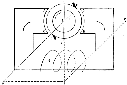
Fig. 684.--Diagram illustrating forces acting on a dynamo armature. In the figure the normal field magneto-motive force is in the direction of the line 1, 2, produced by the field circuit G, if there were no current in the armature. But as soon as the armature current flows, it produces the opposing force 3, 4, which must be combined with 1, 2 to give the resulting force to produce magnetism and hence voltage. The resultant 1, 5, if 3, 4 be large enough, does not differ much from the original force 1, 2. Or, expressed in a more physical way, the brushes E, F, rest on the commutator and all the turns embraced by twice the angle 6, 3, F, oppose the flow of flux through the armature core as well as all the turns embraced by twice the angle, 7, 3, E. The remaining turns distort the flux, making the pole corners at A and B denser, and at C and D rarer. So that all the effect is to kill an increase of flux, or voltage. This cross magnetism tends also to decrease the flow of flux, for the extra ampere turns required to force the flux through the dense pole tips are greater than the decreased ampere turns relieved by the reduction of flux at the other pole tips; this follows, since iron as it increases in magnetic density requires ampere turns greater in proportion than the increase of flux.
Instructions for Stopping Dynamos.--When shutting down a machine, the load should first be gradually reduced, if possible, by easing down the engine; then when the machine is supplying little or no current, the main switch should be opened. This reduces the sparking at the switch contacts, and prevents the engine racing.
When the voltmeter almost indicates zero, the brushes should be raised from contact with the commutator. This prevents the brushes being damaged in the event of the engine making a backward motion, which it often does, particularly in the case of [595] a gas engine. On no account, however, should the brushes be raised from the commutator while the machine is generating any considerable voltage; for not only is the insulation of the machine liable to be damaged, but in the case of large shunt dynamos, the person lifting the brushes is liable to receive a violent shock.
Ques. What attention should the machine receive after it has been shut down?
Ans. It should be thoroughly cleaned. Any adhering copper dust, dirt, etc., should be removed from the armature by dusting with a stiff brush, and the other portions of the machine should be thoroughly cleaned with linen rags. Waste should not be used, as it is liable to leave threads or fluff on the projecting parts of the machine, and on the windings of the armature, which is difficult to remove.
Ques. What attention should be given to the brushes and brush gear?
Ans. They should be examined and thoroughly cleaned. If necessary the brushes should be refitted and readjusted. All terminals, screws, bolts, etc., should be carefully cleaned and screwed up ready for the next run. The brush holders should receive special attention, as when dirty, they are liable to stick and cause sparking. All dirt and oil should be removed from the springs, contacts, pivots, and other working parts.
It is advisable at stated intervals to entirely remove the brush holders from the rocker arms, and give them a thorough cleaning by taking them to pieces, and cleaning each part separately with emery cloth and benzoline or soda solution.
Another point to which particular attention should be given is the cleaning of the brush rocker. This being composed wholly of metal, and the two sets of positive and negative brushes being only separated from it by a few thin insulating washers, it follows that if any copper dust given off by the brushes be deposited in the neighborhood of these washers, there is considerable liability for a short circuit of the machine to occur by the dust bridging across the insulation.
[596] Ques. What further attention should be given?
Ans. It is a good plan, when the machine has been thoroughly cleaned and all connections made secure, to occasionally test the insulation of the different parts. If a record be kept of these tests, any deterioration of the insulation can at once be detected, localized and remedied before it has become sufficiently bad to cause a breakdown.
As a means of protecting the machine from any moisture, dirt, etc., while standing idle, it is advisable to cover it with a suitable waterproof cover.
Series and Parallel Connections.--When it is necessary to generate a large and variable amount of electrical energy, as must be done in central generating stations, apart from the question of liability to breakdown, it is neither economical nor desirable that the whole of the energy should be furnished from a single dynamo. Since the efficiency of a dynamo is dependent upon its output at any moment, or the load at which it is worked (the efficiency varying from about 95 per cent. at full load to 80 per cent. at half load), it is advisable in order to secure the greatest economy in working, to operate any dynamo as near full load as possible.
Under the above circumstances, when the whole of the output is generated by a single dynamo this can evidently not be effected, for the load will naturally fluctuate up and down during the working hours, as the lamps, motors, etc., are switched into and out of circuit; hence, although the dynamo may be working at full load during a certain portion of the day, at other times it may probably be working below half load, and therefore the efficiency and economy in working in such an arrangement is very low.
Ques. How is maximum efficiency secured with variable load?
Ans. It is usual to divide up the generating plant into a number of units, varying in size, so that as the load increases, it can either be shifted to machines of larger size, or when it exceeds the capacity of the largest dynamo, the output of one [598] can be added to that of another, and thus the dynamos actually at work at any moment can be operated as nearly as possible at full load.
Ques. What should be noted with respect to connecting one dynamo to another?
Ans. It is necessary to take certain precautions (as later explained) in order that the other dynamos may not be affected by the change, and that they may work satisfactorily together.
Ques. What are the two methods of coupling dynamos?
Ans. They are connected in series, or in parallel.
In coupling dynamos in series, the current capacity of the plant is kept at a constant value, while the output is increased in proportion to the pressures of the machines in circuit.
When connected in parallel, the pressures of all the machines are kept at a constant value, while the output of the plant is increased in proportion to the current capacities of the machines in circuit.
Coupling Series Dynamos in Series.--Series wound dynamos will run satisfactorily together without special precautions when coupled in series, if the connections be arranged as in fig. 685.
The positive terminal of one dynamo is connected to the negative terminal of the other, and the two outer terminals are connected directly to the two main conductors or bus bars through the ammeter A, fuse F, and switch S. If it be desired to regulate the pressure and output of the machines, variable resistances, or hand regulators R, R1, may be arranged as shunts to the series coils as shown, so as to divert a portion or the whole of the current therefrom.
Series Dynamos in Parallel.--Simple series wound dynamos not being well adapted for the purpose of maintaining a constant pressure, are in practice seldom coupled in parallel; the conditions or working, however, derive importance from the fact that [599] compound dynamos, being provided with series coils, are subject to similar conditions when working in parallel, which is frequently the case.
Ques. What may be said with respect to coupling two or more plain series dynamos in parallel?
Ans. The same procedure cannot be followed as in the case of plain shunt dynamos, for the reason that if the voltage of the dynamo to be coupled be exactly equal to that of the bus bars when connected in parallel, the combination will be unstable.
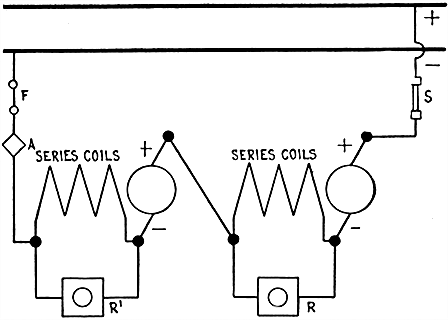
Fig. 685.--Diagram showing method of coupling series dynamos in series. R and R' are two hand regulators which are placed in shunt across the coil terminals to regulate the pressure and output of the machine.
Ques. Why is this?
Ans. If, from any cause, the pressure at the terminals of one of the dynamos fall below that of the others, it immediately takes a smaller proportion of the load; as a consequence, the [600] current in its field coils is reduced, and a further fall of pressure immediately takes place. This again causes the dynamo to relinquish a portion of its load, and again occurs a further fall of pressure. Thus the process goes on, until finally the dynamo ceases to supply current, and the current from the other dynamos flowing in its field coils in the reverse direction reverses its magnetism, and causes it to run as a motor against the driving power in the opposite direction to that in which it previously ran as a dynamo.
Under such circumstances the armature is liable to be destroyed if the fuse be not immediately blown, and in any case it is subjected to a very detrimental shock. This tendency to reverse in series dynamos can be effectually prevented by connecting the field coils of all the dynamos in parallel.
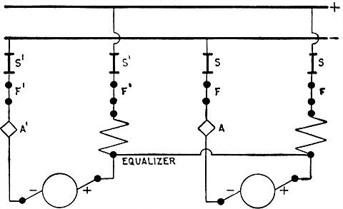
Fig. 686.--Diagram showing method of coupling series dynamos in parallel. In the diagram A, A', are ammeters; F, F', fuses; S, S', switches.
Ques. How are the field coils of all the dynamos connected in parallel?
Ans. This is effected in practice by connecting the ends of all the series coils where they join on to the armature circuit by a [601] third connection, called the "equalizing connection," or "equalizer," as shown in fig. 686.
Ques. What is the effect of the equalizer?
Ans. The immediate effect is to cause the whole of the current generated by the plant to be divided among the series coils of the several dynamos in the inverse ratio of their resistance, without any regard as to whether this current comes from one armature, or is divided among the whole. The fields of the several dynamos being thus maintained constant, or at any rate being caused to vary equally, the tendency for the pressure of one dynamo to fall below that of the others is diminished.
Shunt Dynamos in Series.--The simplest operation in connection with the coupling of dynamos, and the one used probably more frequently in practice than any other, is the coupling of two or more shunt dynamos to run either in series or in parallel. When connected in series, the positive terminal of one machine is joined to the negative of the other, and the two outer terminals are connected through the ammeter A, fuses F, F', and switch S, to the two main conductors or omnibus bars as represented in fig. 687. The machine will operate when the connections are arranged in this manner, if the ends of the shunt coils be connected to the terminals of their respective machines.
Shunt Dynamos in Parallel.--The coupling of two or more shunt dynamos to run in parallel is effected without any difficulty. This method of coupling dynamos is one that is very frequently used. Fig. 688 illustrates diagrammatically the method of arranging the connections. The positive and negative terminals of each machine are connected respectively to two massive insulated copper bars, shown at the top of the diagram, called omnibus bars, through the double pole switches, S, S', and [602] the double pole fuses F, F'. Ammeters, A, A' are inserted in the main circuit of each machine, and serve to indicate the amount of current generated by each. An automatic switch or cutout, Ac, Ac', is also shown as being included in the main circuit of each of the machines, although this appliance is sometimes dispensed with. The pressure of each of the machines is regulated independently by means of the hand regulators R, R', inserted in series with the shunt circuit.
The shunt circuits are represented as being connected to the positive and negative terminals of the respective machines, but in many cases where the load is subjected to sudden variations, and when a large number of machines is connected to the bus bars, the shunt coils are frequently connected direct to these. In such circumstances this method is preferable, as by means of it the fields of the idle dynamos can be excited almost at once direct from the bus bars by the current from the working dynamos; hence, if a heavy load come on suddenly, no time need be lost in building up a new machine previous to switching it into parallel. The pressure of the lamp circuit is given by a voltmeter [603] whose terminals are placed across the bus bars; and the pressure at the terminals of each of the machines is indicated by separate voltmeters or pilot lamps, the terminals of which are connected to those of the respective machines.
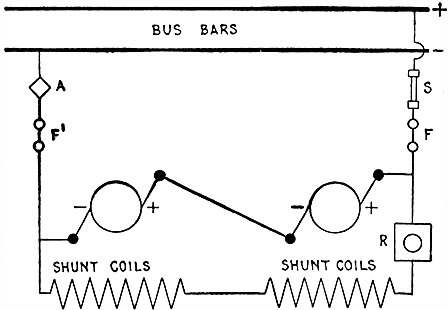
Fig. 687.--Diagram showing method of coupling shunt dynamos in series. The ends of the shunt coils may be connected to the terminals of their respective machine, or they may be connected in series as shown.
Ques. Describe a better method of parallel connection.
Ans. Better results are obtained by connecting both the shunt coils in series with one another, so that they form one long shunt between the two main conductors, the same as in fig. 687.
When arranged in this way, the regulation of both machines may be effected simultaneously by inserting a hand regulator (R) in series with the shunt circuit as represented.
Switching Dynamo Into and Out of Parallel.--In order to put an additional dynamo in parallel with those already working, it is necessary to run the new dynamo up to full speed, and, when it excites, regulate the pressure by means of a hand regulator until the voltmeter connected to the terminals of the machines registers one or two volts more than the voltmeter [604] connected to the lamp circuit, and then close the switch. The load upon the machine can then be adjusted to correspond with that upon the other machines by means of the hand regulator.
Ques. In connecting a shunt dynamo to the bus bars, must the voltage be carefully adjusted?
Ans. There is little danger in overloading the armature in making the connection hence the pressure need not be accurately adjusted.
It is, in fact, common practice in central stations to judge the voltage of the new dynamo merely by the appearance of its pilot lamp.
Ques. How is a machine cut out of the circuit?
Ans. When shutting down a machine, the load or current must first be reduced, by gradually closing the stop valve of the engine, or inserting resistance into the shunt circuit by means of the hand regulator; then when the ammeter indicates nine or ten amperes, the main switch is opened, and the engine stopped.
By following this plan, the heavy sparking at the switch contacts is avoided, and the tendency for the engine to race, reduced.
Ques. What precaution must be taken in reducing the current?
Ans. Care must be taken not to reduce the current too much.
Ques. Why is this necessary?
Ans. There is danger that the machine may receive a reverse current from the other dynamos, resulting in heavy sparking at the commutator, and in the machine being driven as a motor.
Ques. What provision is made to obviate this danger?
Ans. Dynamos that are to be run in parallel are frequently provided with automatic cutouts, set so as to automatically [605] switch out the machine when the current falls below a certain minimum value.
Dividing the Load.--If a plant, composed of shunt dynamos running in parallel, be subjected to variations of load, gradual or instantaneous, the dynamos will, if they all have similar characteristics, each take up an equal share of the load. If, however, as is sometimes the case, the characteristics of the dynamos be dissimilar, the load will not be shared equally, the dynamos with the most drooping characteristics taking less than their share with an increase of load, and more than their share with a decrease of load. If the difference be slight, it may be readily compensated by means of the hand regulator increasing or decreasing the pressures of the machines, as the load varies. If, however, the difference be considerable, and the fluctuations of load rapid, it becomes practically impossible to evenly divide the load by this means.
Under such circumstances, the pressure at the bus bars is liable to great variations, and there is also liability of blowing the fuses of the overloaded dynamos, thus precipitating a general breakdown. To cause an equal division of the load among all the dynamos, under such circumstances, it is needful to insert a small resistance in the armature circuits of such dynamos as possess the straightest characteristics, or of such dynamos as take more than their share of an increase of load. By suitably adjusting or proportioning the resistances, the pressures at the terminals of all the machines may be made to vary equally under all variations of load, and each of the machines will then take up its proper share of the load.
Coupling Compound Dynamos in Series.--Since compound dynamos may be regarded as a combination of the shunt and series wound machines, and as no special difficulties are [606] encountered in running these latter in series, analogy at once leads to the conclusion that compound dynamos under similar circumstances may be coupled together with equal facility.
Ques. How are compound dynamos connected to operate in series?
Ans. The series coils of each are connected as in fig. 685, and the shunt coils are connected as a single shunt as in fig. 687, which may either extend simply across the outer brushes of the machines, so as to form a double short shunt, or may be a shunt to the bus bars of external circuit, so as to form a double long shunt.
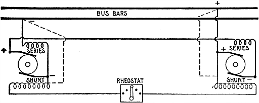
Fig. 689.--Coupling compound dynamos in series; short shunt connection. The dotted lines indicate the changes that would be made for long shunt connection.
Compound Dynamos in Parallel.--Machines of this type will not run satisfactorily together in parallel unless all the series coils are connected together by an equalizing connection, as in series dynamos. The method of arranging the connections [607] as adopted in practice, being illustrated in fig. 690. By means of it idle machines are completely disconnected from those at work.
Ques. How is the equalizer connected?
Ans. The equalizer is connected direct to the positive brushes of all the dynamos, a three pole switch being fitted for disconnecting it from the circuit when the machine to which it is connected is not working. The two contacts of the switch are respectively connected to the positive and negative conductors, while the central contact is connected to the equalizer.
Switching a Compound Dynamo Into and Out of Parallel.--If the characteristics of all the dynamos be similar, and the connections arranged as in figs. 690, or 691, the only precaution [608] to be observed in switching a new machine into parallel is to have its voltage equal, or nearly equal to that of the bus bars previous to closing the switch. If this be the case, the new machine will take up its due share of the load without any shock.
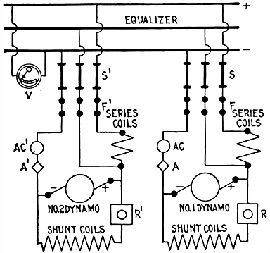
Fig. 691.--Diagram showing another and better method of coupling compound dynamos in parallel. With this arrangement the idle machines are completely disconnected from those at work. The same reference letters are common in both diagrams. S, S' are switches; F, F' fuses; A, A' ammeters, which indicate the total amount of current generated by each of the machines; AC, AC', automatic switches, arranged for automatically switching out a machine in the event of the pressure at its terminals being reduced through any cause; R, R,' are hand regulators, inserted in the shunt circuits of each of the machines, by means of which the pressures of the individual machines may be varied and the load upon each adjusted. The pressure at the bus bars is given by the voltmeter V, one terminal of which is connected to each of the bars; a second voltmeter may be used, to give the pressure of any individual machine, by connecting "voltmeter keys" to the terminals of each of the machines, or a separate voltmeter may be used for each individual machine. The only essential difference between figs. 690 and 691 is, that in fig. 690 the equalizer is connected direct to the positive brushes of all the dynamos, while in fig. 691 the equalizer is brought up to the switchboard and arranged between the two bus bars, a switch being fitted for disconnecting it from the circuit when the machine to which it is connected is not working.
Ques. How is a compound dynamo, running in parallel, cut out of circuit?
Ans. The load is first reduced to a few amperes, as in the case of shunt dynamos, either by easing down the engine, or by [609] cutting resistance into the shunt circuit by means of the hand regulator, and then opening the switch. Previous to this, however, it is advisable to increase the voltage at the bus bars to a slight extent, as while slowing down the engine the load upon the outgoing dynamo is transferred to the other dynamo armatures, and the current in their series coils not being increased in proportion, the voltage at the bus bars is consequently reduced somewhat.
Equalizing the Load.--When a number of compound dynamos of various output, size, or make, are running together in parallel, it frequently happens that all their characteristics are not exactly similar, and therefore the load is unequally distributed, some being overloaded, while others do not take up their proper share of the work.
NOTE.--The action of an equalizing bar in equalizing the load on compound dynamos run in parallel may be explained as follows: The compound winding of a dynamo raises the pressure in proportion to the current flowing through it, and if, in a system of parallel operated compound dynamos without the equalizing connection, the current given by one machine were slightly greater than the currents from the others, the pressure of that machine would increase. With this increase in pressure above the other machines, a still greater current would flow, and so raise the pressure further. The effect is therefore cumulative, and in time the one dynamo would be carrying too great a proportion of the whole current of the system. With the equalizing connection, whatever the current flowing from each machine, the currents in the various compound windings are all equal, and so the added pressure due to the compound winding is practically the same in each machine. Any inequality in output from the machines is readily eliminated by adjusting the shunt currents by means of the shunt rheostats. When compound wound dynamos are operated in parallel, the equalizer bar insures uniform distribution among the series coils of the machines.
NOTE.--To secure the best results in parallel operation, dynamos should be of the same design and construction and should possess as nearly as possible the same characteristics; that is, each should respond with the same readiness, and to the same extent, to any change in its field excitation. Any number of such machines may be operated in parallel. The usual practice is to connect the equalizer and the series field to the positive terminal, though if desired, they may be connected to the negative terminal; both however, must be connected to the same terminal. The resistance of the equalizer should be as low as possible, and it must never be greater than the resistance of any of the leads from the dynamos to the bus bar. Sometimes a third wire is run to the switchboard from each dynamo and there connected to an equalizer bar, but the usual practice is to run the equalizer directly between the dynamos and to place the equalizer switches on pedestals near the machines. This shortens the connections and leads to better regulation. The positive and equalizer switches of each machine differ in pressure only by the slight drop in the series coil, and in some large stations these two switches are placed side by side on a pedestal near the machine. In such cases, the equalizer and positive bus bars are often placed under the floor near the machines, so that all leads may be as short as possible. If all the dynamos be of equal capacity, all the leads to bus bars should be of the same length, and it is sometimes necessary to loop some of them.
[610] If the difference be small, it may be compensated by means of the hand regulator; if large, however, other means must be taken to cause the machines to take up their due proportion of the load.
If the series coils of the several dynamos be provided with small adjustable resistances, in the form of German silver or copper ribbon inserted in series with the coils, the distribution of the current in the latter may be altered by varying the resistance attached to the individual coils. The effect of the series coils upon the individual armatures in raising the pressure may be adjusted, and the load thus evenly divided among the machines.
Shunt and Compound Dynamos in Parallel.--It is not practicable to run a compound dynamo and a shunt dynamo in parallel, for, unless the field rheostat of the shunt machine be adjusted continually, the compound dynamo will take more than its share of the load.
This trouble is of frequent occurrence in both old and new machines. If a dynamo fail to excite, the operator should first see that the brushes are in the proper position and making good contact, and that the external circuit is open if the machine be shunt wound, and closed if series wound.
In starting a dynamo it should be remembered that shunt and compound machines require an appreciable time to build up, hence, it is best not to be too hasty in hunting for faults.
The principal causes which prevent a dynamo building up are:
Brushes not Properly Adjusted.--If the brushes be not in or near their correct positions, the whole of the voltage of the armature will not be utilized, and will probably be insufficient to [612] excite the machine. If in doubt as to the correct positions, the brushes should be rotated by means of the rocker into various points on the commutator, sufficient time being given the machine to excite before moving them into a new position.
Defective Contacts.--If the different points of contact of the connections of the machine be not kept thoroughly clean and free from oil, etc., it is probable that enough resistance will be interposed in the path of the exciting current to prevent the machine building or exciting. Each of the contacts should therefore be examined, cleaned, and screwed up tight.
Ques. Which of the contacts should receive special attention?
Ans. The contact faces of the brushes and surface of the commutator. These are very frequently covered with a slimy coating of oil and dirt, which is quite sufficient to prevent the machine exciting.
Incorrect Adjustment of Regulators.--When shunt and compound machines are provided with field regulators, it is possible that the resistance in circuit may be too great to permit the necessary strength of exciting current passing through the field windings. Accordingly, the fault is corrected by cutting out more or less of the resistance. The field coils of series machines are sometimes provided with short circuiting switches or resistances arranged to shunt the current across the field coils. If too much of the current be shunted across, the switch should be opened, or if there be a regulator, it should be so adjusted that it will pass enough current through the field windings to excite the machine.
[613] Speed too Low.--In shunt and compound dynamos there is a certain critical speed below which they will not excite. If the normal speed of the machine be known, it can be seen whether the failure to excite arises from this cause, by measuring the speed of the armature with a speed indicator. In all cases it is advisable, if the machine do not excite in the course of a few minutes, to slightly increase the speed. As soon as the voltage rises, the speed may be reduced to its regular rate.
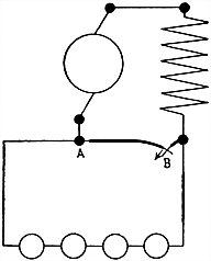
Fig. 692.--Method of testing for break by short circuiting the terminals of the machine. If the external circuit test out apparently all right, and there be no defective contacts in any part of the machine, and all short circuiting switches, etc., be cut out of circuit, the machine still refusing to excite, short circuiting the terminals of the machine should be tried. This should be done very cautiously, especially in case of a high tension machine. It is advisable to have, if possible, only a portion of the load in circuit, and the short circuit should be effected as shown in the figure. The short circuit may be made by momentarily bridging across the two terminals of the machine with a single piece of wire. As this, however, is liable to burn the terminals, a better plan is to fix a short piece of scrap wire in one terminal, and then with another piece of insulated wire make momentary contacts with the other terminal and the short piece of wire. If the machine excite, it will be at once evident by the arc which occurs between the two pieces of wire. As the voltage of a series machine when induced to build in this manner generally rises very rapidly, great care should be taken that the contact is at first only momentary, merely a rubbing or scraping touch of the wires. The contact may be prolonged if the machine do not excite at the first contact. Compound wound machines can often be made to excite quickly by short circuiting their terminals in this manner.
[614] Insufficient Residual Magnetism.--This fault is not of frequent occurrence; it takes place chiefly when the dynamo is new, and may be remedied by passing the current from a few storage cells, or from another dynamo, for some time in the proper direction through the field coils. If a heavy current, such as is obtainable from a storage battery, be not available, and the machine be shunt or compound wound, a few primary cells arranged as in fig. 693 will generally suffice.
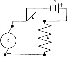
Fig. 693.--Method of overcoming insufficient residual magnetism. The flexible "lead" L of the dynamo D is disconnected from the positive terminal of the machine, and is connected to the negative or zinc pole of the battery B, the other or positive carbon pole being connected to the terminal, from which the lead was removed, and shunt circuit S. As thus arranged, it will be seen that the battery B is in series with the armature and shunt circuit, and therefore its voltage will be added to any small voltage generated in the armature. When the machine is started, the combined voltages will probably be able to send sufficient current through the shunt to excite the machine. As the voltage rises and the strength of the current in the shunt windings increases, the flexible lead may be again inserted into the terminal from which it was removed. The battery will thus be short circuited, and may be cut out of circuit without any danger of breaking the shunt circuit, and thus causing the machine to demagnetize.
Open Circuits.--Dynamos are affected by open circuits in different ways, depending upon the type. Series machines require closed circuit to build up, while an open circuit is necessary [615] with the shunt machine. An open circuit may be due to: 1, broken wire or faulty connection in the machine; 2, brushes not in contact with commutator; 3, safety fuse blown or removed; 4, circuit breaker open; 5, switch open; 6, external circuit open. If the trouble be due merely to the switch or external circuit being open, the magnetism of a shunt machine may be at full strength, and the machine itself may be working perfectly, but if the trouble be in the machine, the field magnetism will probably be very weak. Open circuits are most likely to occur in:
When the open circuit is due to the brushes not making good contact, simple examination generally reveals the fact.
Ques. What causes breaks in the field circuit?
Ans. Bad contacts at the terminals, broken connections, or fracture of the coil windings.
Ques. How is the field circuit tested for breaks?
Ans. The flexible leads attached to the brushes are removed from their connections with the field circuit, and the latter is then tested for conductivity with a galvanometer.
Ques. Where is a break likely to occur in a shunt machine?
Ans. In the hand regulator through a broken resistance coil or bad contact.
Very frequently the fault occurs in the connecting wires leading from the machine to the hand regulator fixed upon the switchboard, or in the short wires connecting the field coils to the terminals or brushes.
[616] The insulation of a broken wire will sometimes hold the two ends together so as to defy any but the most careful inspection or examination; therefore, in order to avoid loss of time, it is advisable to disconnect the wires if possible, and test each separately for conductivity with a battery and galvanometer connected, as in fig. 694. If the fault be not located in the various connections, the magnet coils should be tested with the battery and galvanometer coupled up as in fig. 706, care being first taken to disconnect the ends of each of the coils. A faulty coil will not show any deflection of the galvanometer.
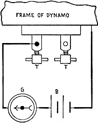
Fig. 694.--Method of testing dynamo for short circuits. In the figure, one pole of the battery B is placed in contact with the frame of the machine at a point which has previously been well scraped and cleaned; the other pole is connected to one of the galvanometer terminals as shown. The other terminal of the galvanometer is connected to each of the dynamo terminals T T under test in turn. If a deflection of the needle be produced when the galvanometer terminal is in contact with either, the terminals are in contact with the frame, and they should then be removed, and the fault repaired by additional insulation or by reinsulating.
Ques. At what point of a shunt coil does a break usually occur?
Ans. At the point where the wire passes through the flanges of the spool or bobbin.
[617] Ques. How should the coil be repaired?
Ans. In most cases a little of the wood or metal of which the flange is made can be gouged or chipped out, and a new connecting wire soldered on to the broken end of the coil without much difficulty.
If it be necessary to take the magnets apart at any time, care should be taken in putting them together again to wipe all faces perfectly clean, and screw up firmly into contact, and to see that the connections of the coils are made as they were before being taken apart.
If the faulty coil cannot be repaired quickly, and the machine is urgently required, the coil may be cut out of circuit entirely, or short circuited, and the remaining coils coupled up so as to produce the correct polarity in the pole pieces.
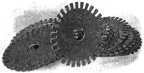
Fig. 695.--Watson armature discs. Each lamination is made from low carbon electrical steel of high magnetic permeability. Each disc is annealed and afterwards varnished.
Ques. What trouble is liable to be encountered in operating after cutting out a coil?
Ans. The remaining coils are liable to heat up to a greater extent than formerly, owing to the increased current, hence it is advisable to proceed cautiously in starting the dynamo, since the temperature may exceed a safe limit. If this occur, a resistance may be put in circuit with the field coils, or the speed of the dynamo reduced.
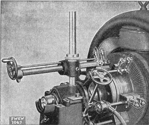
Fig. 696.--Fort Wayne pedestal type commutator truing device. When this device is used, the armature is revolved in its own bearings by means of a handle clamped to the pulley. The tool has a horizontal travel of 21 ins., (being 3 ins. wide inside the fastening bolt in the base), and a vertical adjustment of 12 ins., adapting it to machines with commutators up to 36 ins. in diameter.
Fig. 697.--Fort Wayne yoke type commutator truing device for machines having brush mechanism mounted on a yoke carried by the field frame. It consists of a carriage for the tool holder having a screw feed and a bracket for attaching to the brush yoke. The bracket replaces two brush holder brackets on the brush yoke, and is made to fit the yoke of the particular machine on which it is to be used.
[619] Ques. What kind of dynamo is affected by breaks in the external circuit?
Ans. A series dynamo.
Ques. Name the kind of break that is difficult to locate.
Ans. A partial break.
Short Circuits.--In a series or compound dynamo a short circuit or heavy load will overload the machine and cause the fuses to blow. A shunt machine will not excite under these circumstances, for the reason that practically the whole of the current generated in the armature passes direct to the external circuit, and the difference of potential between the shunt terminals is practically nil.
Ques. What should be done if it be suspected that the failure to excite arises from this cause?
Ans. The main leads should be taken out of the dynamo terminals, then, if due to this cause, the machine will excite.
Ques. What parts of a dynamo are specially liable to be short circuited?
Ans. The terminals, brush holders, commutator, armature coils and field coils.
Ques. How are the terminals liable to be short circuited?
Ans. The terminals of the various circuits of the machine are liable to be short circuited, either through metallic dust bridging across the insulation, or through the terminals making direct contact with the frame of the machine.
The various terminals should be examined, and if the fault cannot be located by inspection, they should each be disconnected from their circuits and tested with a battery and galvanometer arranged as in fig. 694.
[620] Ques. What precaution should be taken with the brush holders?
Ans. Since, they are liable to be short circuited through the rocker by metallic dust lodging in the insulating washers, they should be kept clean.
Ques. How are the brush holders tested?
Ans. A galvanometer and battery are connected in series with one terminal of the galvanometer connected to one set of brushes; the unconnected terminal of the battery is then connected with the other set of brushes. A deflection of the needle will indicate a short circuit.
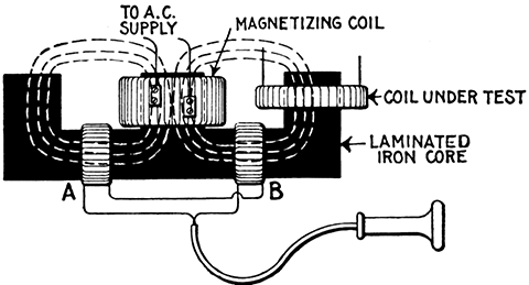
Fig. 698.--Field coil testing with telephone receiver. In the method here shown, a telephone receiver is connected in series with two symmetrically placed coils A and B. Very little sound will be heard when the flux through the two coils AB is the same; but if a short-circuited coil is being tested, the fluxes through the coils A, B will not be equal and a noise can be heard in the receiver.
Ques. What is the effect of a short circuit in the field coils or field circuit?
Ans. The machine generally refuses to excite.
Ques. How are the field coils tested for short circuit?
Ans. By measuring the resistance of each coil with an ohmmeter or Wheatstone bridge. The faulty coils will show a much less [621] resistance than the perfect coils. The fault may also be discovered and located by passing a strong current from a battery or another dynamo through each of the coils in turn, and observing the relative magnetic effects produced by each upon a bar of iron held in their vicinity.
The short circuit may be in the terminals or connections, and these should first be examined and tested.
Some series dynamos are provided with a resistance, arranged in parallel or shunt with the field coils, to divert a portion of the current therefrom, and thus regulate the output.
When making a series dynamo excite, all resistances and controlling devices should be temporarily cut out of circuit by opening the shunt circuit. Series machines have frequently a switch which short circuits the field coils. Care should be taken that this is open, or otherwise the machine will not excite.
Fig. 699.--Watson armature complete. The armature coils are form wound, heavily insulated and so mounted on the core as to insure rapid dissipation of heat by ventilation. Each coil is protected by an insulating sheath and tape covering before mounting. The armature is baked after the coils are mounted to drive out all moisture, then, while hot, is treated with insulating compound and again baked twelve hours.
Wrong Connections.--When a machine is first erected, the failure to build up may be due to incorrect connections. The whole of these latter should therefore be traced or followed [622] out, and compared with the diagrams of dynamo connections given in figs. 190 to 198.
Sometimes errors are made in connecting the field coils, causing them to act in opposition. This may occur when the dynamo is a new one or the coils have been removed for repairs. It may be caused either through the coils having been put on the field cores the wrong way, or through incorrect coupling up. Under these circumstances, the dynamo, if bipolar, will fail to excite; and if multipolar, poles will be produced in the yokes, etc. It may be remedied by removing one of the coils from the core and putting it on the reverse way, or by reversing its connections. The correctness of connections of all the coils should be verified.
In compound dynamos it sometimes happens that the machine will excite properly, but that the series coils tend to reverse the polarity of the dynamo, thus reducing the voltage as the load upon the machine increases. This may be detected when the machine is loaded by short circuiting the series coils, not the terminals. If the voltage rise in doing this, the series coils are acting in opposition to the shunt coils, and the connections of the series coils must be reversed.
Reversed Field Magnetism.--This is sometimes caused by the nearness of other dynamos, but is generally due to reversed connections of the field coils. Under such conditions the field coils tend to produce a polarity opposed to the magnetization to which they owe their current, and therefore the machine will refuse to excite until the field connections are reversed, or a current is sent from another dynamo or a battery through the field coils in a direction to produce the correct polarity in the pole pieces.
A large proportion of the mishaps and breakdowns which occur with dynamos and motors arise from causes more strictly within the province of the man in charge than in that of the designer. The armature, being a complex and delicately built structure, is subject in operation to various detrimental influences giving rise to faults.
Many of the faults which occur are avoided by operators better informed as to the electric and magnetic conditions which obtain in the running of the machine, especially the mechanical stresses on the copper inductors due to the magnetic field and the necessity of preserving proper insulation.
The chief mishaps to which armatures are subject are as follows:
[624] Short Circuit in Individual Coils.--This is a common fault, which makes its presence known by a violent heating of the armature, flashing at the commutator, flickering of the light on lighting circuits, and by a smell of burning varnish or overheated insulation. When these indications are present, the machine should be stopped at once, otherwise the armature is liable to be burnt out. The fault is due either to metallic dust lodging in the insulation between adjacent bars of the commutator, or to one or more convolutions of the coils coming into contact with each other, either through a metallic filing becoming embedded in the insulation or damage to the insulation.
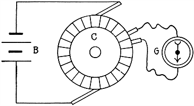
Fig. 700.--Method of locating short circuited armature coil. Disconnect the external and field circuits from the armature, and pass a large current--say from 20 to 100 amperes--from a battery (B) or another dynamo through the whole armature by means of the brushes. Then, having previously well cleaned the commutator, measure the difference of potential between adjacent segments all round the commutator (C), by means of a voltmeter or galvanometer (G), the terminals of which are connected to adjacent segments, as shown. The short circuited coil or coils will be located by the difference of potential between the corresponding segments being little or nothing. It may be remarked, however, that this is not always a decisive test. In some cases the short circuit may be intermittent, or may disappear as soon as the armature ceases to rotate. In such cases, the short circuit is caused by the wire coming into contact through the action of the centrifugal forces developed by the rotation of the armature.
Ques. How is the faulty coil located?
Ans. When the machine is stopped, the faulty coil, if not burnt out, can generally be located by the baked appearance of the varnish or insulation, and by its excessive temperature over [625] the rest of the coils, being detected also by the baked appearance of the varnish or insulation.
Ques. What should be done if the machine do not build, and it be suspected that the fault is due to short circuited armature coils?
Ans. The field magnets should be excited by the current from a storage battery or another dynamo, and, having raised the brushes from contact with the commutator, the armature should be run for a short time. In stopping, the faulty coil or coils may be located by the heat generated by the short circuit.
When the dynamo is started for the purpose of localizing a short circuit, precautions should be taken, and the machine only run for a few minutes at a time until the faulty coil is detected.
When the faulty coil has been located, the insulation between the segments of the commutator to which its ends are connected should be carefully examined for anything that may bridge across from segment to segment, and scraped clean. If the commutator be apparently all [626] right, the fault probably lies in the winding. The insulation of the winding should be carefully examined, and any metallic filings or other particles discovered therein carefully removed, and a little shellac varnish applied to the faulty part.
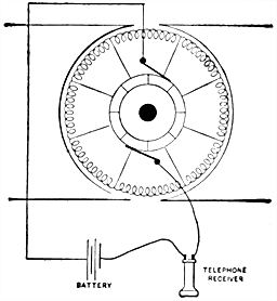
Fig. 701.--Test for break in armature lead. Clean the brushes and commutator, and apply current from a few cells of battery having a telephone receiver in circuit as shown in the figure. If the machine have more than two brushes, connect the leads to two adjoining brushes and raise the others. Now rotate the armature slowly by hand and there will be a distinct click in the receiver as each segment passes under the brushes until one brush bears on the segment at fault, when the clicking will cease. In making this test, the brushes must not cover more than a single segment.
Ques. If the insulation on adjacent conductors has been abraded, how should it be repaired?
Ans. A small boxwood or other hardwood wedge, coated with shellac varnish should be driven in tightly between the wire; this will generally be sufficient.
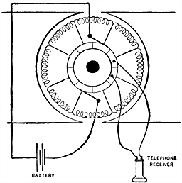
Fig. 702.--Bar to bar test for open circuit in coil or short circuit in one coil or between segments. If, in testing as in fig. 701, on rotating the armature completely around, the receiver indicate no break in the leads, connect the battery leads directly to the brushes, as shown in the above figure, and touch the connections from the receiver to two adjacent bars, working from bar to bar. The clicking should be substantially the same between any two commutator bars; if the clicking suddenly rise in tone between two bars, it indicates a high resistance in the coil or a break (open circuit).
Ques. If a faulty coil cannot be quickly repaired and the dynamo be needed, what should be done?
Ans. The coil may be cut out of circuit, and the corresponding commutator segments connected together with a piece of wire (of a size proportionate to the amount of current to be carried), soldered to each. It will not be necessary to cut out and remove the entire coil.
[627] If the active portions only be separated so that they do not form a closed circuit, it will answer the purpose. If the wires be cut with a chisel at the point where they pass over the ends of the core, and the ends separated, it will be quite as effective as removing the entire coil. It is wise, of course, to rewind the coil at the first opportunity.
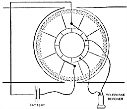
Fig. 703.--Alternate bar test for short circuit between sections. Where two adjacent commutator bars are in contact, or a coil between two segments becomes short circuited, the bar to bar test described in fig. 702 will detect the fault by the telephone receiver remaining silent. If a short circuit be found, the leads from the receiver should then include or straddle three commutator bars, as here shown. The normal click will then be twice that between two segments until the faulty coils are reached, when the clicking will be less. When this happens, test each coil for trouble and, if individually they be all right, the trouble is between the two. To test for a ground place one terminal of the receiver on the shaft or frame of the machine, and the other on the commutator. If there be a click it indicates a ground. Move the terminal about the commutator until the least clicking is heard and at or near that point will be found the contact. Grounds in field coils can be located in the same manner.
Short Circuits between Adjacent Coils.--In ring armatures the presence of this fault does not necessarily imply that the machine will not build; in drum armatures, wound into a single layer of conductors, it entirely prevents this occurring.
Reference to a winding diagram will show that adjacent coils are during a certain period of the revolution at the full difference of pressure generated by the machine. Hence, if any two adjacent coils be connected together or short circuited, the whole of the armature will be practically closed on itself, any current generated flowing within the armature only.
[628] Large drum armatures wound with compressed and stranded bars and connectors are particularly susceptible to this fault, a slight blow generally forcing one or more of the strands into contact with the adjacent bars, thus short circuiting the armature, and rendering it practically useless so far as the generation of current is concerned. In this class of short circuit in drum armatures, the method of locating the faulty coils by exciting the field, and running the armatures on open circuit, does not apply, for the reason that the whole armature will be heated equally.
A method of locating such fault is illustrated in fig. 704. This applies to drum wound armatures. Faults of this description can frequently be discovered by a careful inspection of the windings of the armature without recourse to testing. When located, the fault can usually be repaired with a hardwood wedge, as explained above, or a piece of mica or vulcanized fibre cemented in place with shellac varnish.
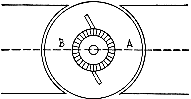
Fig. 704.--Method of locating short circuits between adjacent armature coils. Fasten a monkey wrench to the rim of the pulley, or a crank to the shaft. Now, excite the fields, and, to make the effects more marked, connect the coils in parallel. When this has been done it will require considerable force to rotate the armature, and then it will move quite slowly, except at one position. When this position has been found, mark the armature at points in the center of the pole pieces at points A and B and at both ends of the armature. The explanation is that both halves of the armature oppose one another at this position; but when not at these points a continuous circuit is formed, and the resultant magnetic effect is considerable. The "cross" or "short" circuit is nearly always found on the commutator end in the last half of the winding, where the wires pass down through the first half terminals. This applies to an unequal winding. In armatures where the windings are equal, it is as liable to occur at one point as at another. With this method a defect can be found and remedied in a few moments, for it has always been a simple matter to repair it when discovered. These results can be observed in a perfect armature by connecting the opposite sections of the commutator.
[629] Short Circuits between Sections through Frame or Core of Armature.--Detection of this fault can be effected by the methods described above, and by disconnecting the whole of the armature coils from the commutator and from each other, and testing each separately with a battery and galvanometer coupled up as in fig. 705, one wire being connected to the shaft and the other to the end of the coil under test. As a rule, there is no way of remedying this fault other than unwinding the defective coils, reinsulating the core, and rewinding new coils.
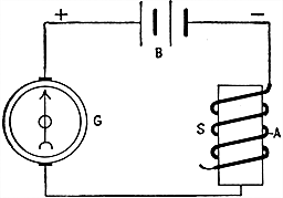
Fig. 705.--Method of locating short circuits between coils through armature core. The galvanometer, battery and coil to be tested are connected in series as shown, and then the unconnected terminal of the galvanometer is brought into contact with the shaft. If then some portion of the insulation of the wire has been abraded or destroyed, thus bringing the bare wire into contact with the metal core, as at A in the figure, the needle of the galvanometer will be deflected since a closed circuit is formed through the core and wire. If the insulation be perfect, the needle will not be deflected. It will thus be seen that in the conductivity test (fig. 700) it is necessary that the needle should be deflected, or turned, to prove that all is right, while in the insulation test the converse holds good; if the needle be deflected, it proves that the insulation is broken down.
Short Circuits between Sections through Binding Wires.--This fault is the result of a loose winding, and is caused by the insulation upon which the binding wires are wound giving way, thus bringing coils at different pressures together. As a consequence of the heavy current which flows, the binding wires are as a rule unsoldered or burned. The location of the fault can [630] therefore be effected by simple inspection. To remedy, it will be necessary to unwind and rewind on new binding wires, on bands of mica or vulcanized fibre, soldering at intervals to obviate flying asunder.
Partial Short Circuits in Armatures.--This is usually due to the presence of moisture in the windings. To remedy the fault, the armature should be taken out and exposed to a moderate heat, or subjected to a current equal to that ordinarily given by the dynamo. Under the action of heat or of this current the moisture will be gradually dispersed. When thoroughly dry, and while still warm, a coat of shellac should be applied to the whole of the windings.
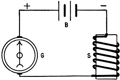
Fig. 706.--Method of testing for breaks. The instruments are connected as shown. B is the battery, G the galvanometer, and S the coil of wire being tested. One terminal of the battery is connected to a terminal of the galvanometer, and the other to one of the ends of the coil under test. The other terminal of the galvanometer is connected to the other end of the coil. If the connecting wires be making good electrical contact with the respective terminals, and the wire of coil being tested be unbroken, the needle of the galvanometer will be deflected as soon as a closed circuit is made by the end of the coil coming into contact with the galvanometer terminal. If the wire of the coil be broken in some part or the ends of the connecting wires do not make good electrical contact with the terminals, the needle will not be deflected. In order to prevent mistakes, it is advisable to test the battery and galvanometer connections and contacts by short circuiting or bringing the ends of the wire connecting the terminal of the galvanometer and negative pole or the battery together before starting to test the circuit or coil. If the needle be deflected, the connections are all right; if not deflected, there is a bad contact somewhere, which must be made good before the test can proceed.
[631] Burning of Armature Coils.--The reason for the burning of an armature coil may be explained as follows: The coil, segments, and the short circuit between the segments form a closed circuit of low resistance so that it is only necessary to have a low pressure set up in the active portion of the coil to force a very large current through the coil and the short circuited commutator bars. The heating effect of this current is sufficient to burn out the coil.
Fig. 707.--Watson field coils. Automatic machinery is employed to wind these coils; after winding, they are bound with tape, then baked to expel all moisture, and while hot, are saturated with an insulating compound and again baked for twelve hours to make them practically oil and water proof. Heavy flexible leads are brought out to avoid danger of breaking or other damage.
Cutting Out Damaged Armature Coils.--To cut out a damaged coil from an armature, first, disconnect the coil from the commutator, and after cutting off the leads, insulate the exposed parts with tape. Then connect the commutator bars (which were connected with the leads) with a wire of the same size as the wire winding.
To remove the coil entirely, cut the band wire or remove the wedges, and lift up a sufficient number of leads and coils to permit of the removal of the damaged coil.
[632] Grounds in Armatures.--These faults occur when the armature coils become connected to the frame or core of the armature. When this grounding is confined to a single coil, it is not in itself liable to do damage. A simple method of locating a grounded coil is illustrated in fig. 708.
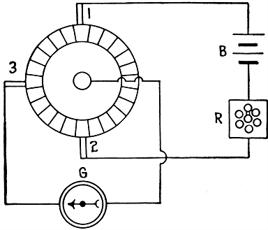
Fig. 708.--Method of locating grounded armature coil. B is a battery or dynamo circuit giving a current of a few amperes through the armature by its own brushes (1 and 2). At G is placed a roughly made galvanometer, to carry some 25 amperes or so, one terminal being in connection with the shaft of the armature, and the other attached to a movable brush 3. Since the function of the particular galvanometer is simply to show a deflection when a current is passing, and to mark zero when there is none, a coil of thick wire with a pocket compass in the center will do all that is required, but care must be taken to remove it sufficiently far away from the disturbing effects of the armature magnetism. The manner of testing is as follows: Assume a steady current to be flowing from battery B through the armature; touch the commutator with brush 3, and a current will flow through G. Slowly rotate the armature or the brush 3 until the galvanometer G shows no deflection. The coil in contact with 3 will be found to be grounded. A hand regulator or rheostat R may be inserted in series with the battery or dynamo circuit to regulate the strength of the current passing.
Ques. What is the advantage of this test?
Ans. The damaged coil can be located without unsoldering the coils from the commutator, which is sometimes a difficult operation without proper tools; further, the fault can frequently be repaired without disconnecting any of the wires if its exact position be determined.
[633] Magneto Test for Grounded Armatures.--A magneto test for grounded armatures is not to be recommended, as armatures often possess sufficient static capacity to cause a magneto to ring even though there be no leak. This is due to the alternating current given by the magneto for when the circuit has capacity it acts as a condenser and at each revolution of the armature of the magneto a rush of current goes out and returns, charging the surfaces of the conductor alternately in opposite directions, and ringing the bell during the process.
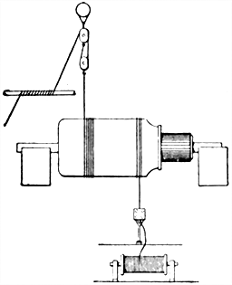
Fig. 709.--Method of binding armature winding. Complete appliances for handling armatures in making repairs are usually not available with most street railway companies, since they are so seldom required. When needed, therefore, some temporary contrivance must be resorted to for help in the dilemma. Should an armature burn out, some local concern that makes coils and rewinds armatures may be available to do the work; again, it will be necessary to send to the manufacturers for a man, as soon as coils can be made ready for the work. In no case should any but an experienced man be given charge of this work. But if there be any doubt as to whether the armature is really burnt out, let a competent man be the judge. When a large armature needs repairing, a pair of chain tongs can be used on some part of the shaft when putting in the coils, and a block and tackle, as shown, can be used, when putting on the band wires. Do not finish one band and then cut off the wire, but run it over for the next, etc. Then solder and trim off the wires.
Breaks in Armature Circuit.--A partial or complete break in the armature circuit is always accompanied by heavy sparking at the commutator, but not, as a rule, by an excessive heating of the armature or slipping of the belt, and this enables the fault to be distinguished from a short circuit. The faulty part can always be readily located by the "flat" which it produces [634] upon the surface of the commutator. The armature circuit being open at the faulty part, heavy sparking results at every half revolution as the brushes pass over it, and as a consequence the corresponding segments become "pitted" or "flattened" with respect to the others; they may easily be discovered on examination.
Breaks in the armature circuit may occur in either the commutator or in the coils of the armature. To ascertain whether it be in the latter, carefully examine the winding of the faulty coil.
The defect may be sought for more particularly at the commutator end of the armature, as breaks in the wire are most frequent where the connections are made with the commutator segments. If no break can be discovered, try passing a heavy current through the faulty coil by means of the brushes.
If a partial break exist with sufficient contact to pass a current, the coil will be heated at that point and may be discovered by running the fingers over the coil.
When located, the fault may be repaired by rewinding the coil, or carefully cleaning the broken ends and jointing.
The fault may also be temporarily repaired by soldering the adjacent commutator segments together without disconnecting the coil.
For satisfactory operation, the brushes and commutator must be kept in good condition. To this end the main thing to be guarded against is the production of sparks at the brushes. If care be taken in the first instance to adjust the brushes to their setting marks, and to regulate their pressure upon the commutator, and afterwards to attend to the lead as the load varies, so that little or no sparking occurs, and also to keep the brushes and commutator free from dirt, grit, excessive oil, etc., the surface of the commutator will assume a dark burnished appearance and wear will practically cease. Under these circumstances the commutator will run cool, and will give very little trouble.
In order to maintain these conditions it will only be necessary to see that the brushes are kept in proper condition and fed forward to their setting marks, as they wear away, and that the commutator is occasionally polished.
If the pressure of the brushes upon the commutator be too great, or their adjustment faulty, or the commutator be allowed to get into a dirty condition, sparking will result, and, if not at once attended to and remedied, the brushes will quickly wear away, and the surface of the commutator will be destroyed. As this action takes place, in the earlier stages, the surface of the commutator will become roughened or scored, resulting in [636] jumping of the brushes, and increased sparking; in the later stages, the commutator will become untrue and worn into ruts, moreover, owing to the violent sparking which takes place through this circumstance, the machine will quickly be rendered uselessD.
[D] NOTE.--In operating dynamos having metal brushes, it is of importance to keep the commutator smooth and glossy. To accomplish this, it is necessary to keep the commutator and brushes clean and free from grit, and to occasionally lubricate the commutator with some light oil, such as ordinary machine oil. This should be done daily if the machine be in constant use. Keep the brushes resting upon the commutator with just enough pressure to insure a good firm contact. This will be found to be much less than the springs are capable of exerting. A good method to follow in cleaning the machine is as follows: Loosen the brush holder thumb screws and tilt the brushes off the commutator (or, if box brush holders be used, take them out of their holders). Then run the machine and hold a clean cloth against the commutator. After the commutator is clean, hold against it a cloth or piece of waste moistened with machine oil and reset the brushes. If for any reason the brushes begin to cut or score the commutator, it may be readily detected by holding the finger against the commutator; the ridge may be easily felt by the finger. This should be attended to at once in the following manner: Tilt back the brushes (or if box brushes are used take them out of their holders), and hold lightly against the commutator a piece of No. 00 sandpaper well moistened with oil, passing it back and forth until the surface is perfectly smooth. Then wipe off the commutator with a clean piece of cloth or waste and lubricate with another clean piece moistened with oil and reset the brushes.
Ques. How is the commutator easily tested as to the condition of its surface?
Ans. It is readily tested by resting the back of the finger nail upon it while in motion; the nail being very sensitive to any irregularities, indicates at once any defect.
Ques. What causes grooves or ridges to be cut in the commutator?
Ans. They result from using brushes with hard burnt ends which are not pliable; also by too great a pressure of the brush upon the commutator surface.
Sparking at the brushes is expensive and detrimental, chiefly because it results in burning the brushes and also the commutator, necessitating their frequent renewal. Every spark consumes a particle of copper, torn from the commutator or brush. The longer the sparking continues, the greater the evil becomes, and the remedy must be applied without delay.
Ques. What kind of oil should be used on the commutator?
Ans. Mineral oil.
Ques. What attention should be given to the brushes?
Ans. At certain intervals, according to the care taken to reduce sparking and the length of time the machine runs, the brushes will fray out or wear unevenly, and will therefore need trimming. They should then be removed from the brush holders and their contact ends or faces examined. If not truly square, [637] they should be filed or clipped with a pair of shears, the course of treatment differing with the type of brush.
If the machine be fitted with metal strip brushes, frayed ends should be clipped square with a pair of shears, the ends thoroughly cleaned from any dirt or carbonized oil, and replaced in their holders. Gauze and wire brushes require a little more attention. When their position on the commutator has been well adjusted and looked after, so that little or no sparking has taken place, it is generally only necessary to wipe them, clean the brushes and clip off the fringed edges and corners with the shears, or a pair of strong scissors. If, however, the machine has been sparking, the faces will be worn or burnt away, and probably fused. If such be the case, they will need to be put in the filing clamp, and filed true.
A convenient method of trimming carbon brushes, or of bedding a complete new set of metal brushes, is to bind a piece of sandpaper, face outwards, around the commutator after the current has been shut off, and then mount the carbon or metal brushes in the holders, adjusting the tension of the springs so that the brushes bear with a moderately strong pressure upon the sandpaper. Then let the machine run slowly until the ends of the brushes are ground to the proper form. Care should be taken, however, that the metal dust given off does not get into the commutator connections or armature windings, or short circuiting will result.
If the contact faces of the brushes are very dirty and covered with a coating of carbonized oil, etc., it will be necessary to clean them with benzoline or soda solution before replacing.
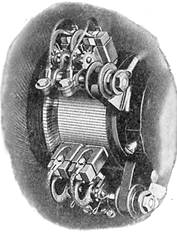
Fig. 710.--Bissell brush gear. The brushes are held in the brushholders radially and work equally well with armature running in either direction. Brushes can be renewed and adjustment made while machine is in operation.
[638] Ques. Describe a filing clamp.
Ans. As usually constructed, it consists of two pieces of metal, both shaped at one end to the correct angle, to which the brushes must be filed. One of the pieces of metal (the back part) has a groove sufficiently large to accommodate the brush, which is clamped in position by the other piece of metal and a pinching screw.
If the clamp be not supplied with the machine a convenient substitute can be made out of two pieces of wood about the same width as the brush. One end of each piece is sawn to the correct angle, and the brush placed between the two.
In filing, the brush is fixed in the clamp, with the toe or tip projecting slightly over the edge of the clamp, and the latter being fixed in a vise, the brush is filed by single strokes of a smooth file made outwards, the file being raised from contact with the brush when making the back stroke.
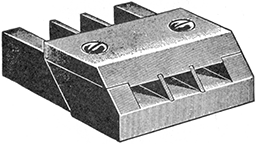
Fig. 711.--Jig for filing brushes to the correct bevel; used with copper brushes to fit them to the commutator.
Sparking.--In all well designed machines there are certain positions upon the commutator for the brushes at which there will be no sparking so long as the commutator is kept clean and in good condition. In other dynamos, badly designed or constructed, sparking occurs at all positions, no matter where the [639] brushes are placed, and in such dynamos it is therefore impossible to prevent this no matter how well they are adjusted.
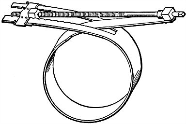
Fig. 712.--Commutator clamp; a useful device for holding the segments firmly in position in taking out the end rings of the commutator to repair for internal grounds. It is made of 2 × 1/8 inch sheet steel, with a 1/2 inch screw. The illustration clearly shows the adjustable fastening. The notches fit around rivets on one side of each fastening, which can be moved by removing the two cotters. The clamp is made loose or taut by screwing the bolt in the nut.
Ques. What two kinds of sparking may be generally distinguished?
Ans. One kind of sparking is that due to bad adjustment of the brushes, and a second kind, that due to bad condition of the commutator.
Sparks due to bad adjustment of the brushes are generally of a bluish color, small when near the neutral plane, and increasing in violence and brilliancy as the brushes recede from the correct positions upon the commutator.
When sparks are produced by dirty or neglected state of the commutator, they are distinguished by a reddish color and a spluttering or hissing. When due to this last mentioned cause, it is impossible to suppress the sparking until the commutator and brushes have been cleaned. In the former case, the sparks will disappear as soon as the brushes have been rotated into the neutral points.
Another class of sparks appear when there is some more or less developed fault, such as a short circuit, or break in the armature or commutator. [640] These are similar in character to those produced by bad adjustment of the brushes, but are distinguished from the latter by their not decreasing in violence when the brushes are rotated towards the neutral plane.
Having distinguished the classes of sparks which appear at the commutator of a dynamo, it remains to enumerate the causes which produce them. These are:
Bad Adjustment of Brushes.--When sparking is produced by bad adjustment of the brushes, it may be detected by rotating or shifting the rocker, by the indication that the sparking will vary with each movement.
To obtain good adjustment of the brushes, it will be necessary to rock them gently backwards and forwards, until a position is found in which the sparking disappears.
Ques. If, in rocking the brushes, a position cannot be found at which the sparking disappears, what is the probable cause of the trouble?
Ans. The brushes may not be set with the proper pitch, that is they may not be separated a correct distance, or the neutral plane may not be situated in the true theoretical position upon the commutator through some defect in the winding, etc.
In this last named case, the brushes may be strictly adjusted to their theoretically correct positions before starting the machine; then, when [641] the machine is started and the load put on, violent sparking occurs, which cannot be suppressed by shifting the rocker. If, however, one set of brushes only be observed, it will generally be found that, at a certain position, the sparking at the set of brushes under observation ceases or is greatly reduced, while sparking still occurs at the other set. When this position is found, the rocker should be fixed by the clamping screw, and the brushes of the other set at which sparking is still occurring adjusted by drawing them back or pushing them forward in their holders until a position is found at which the sparking ceases. Correct position of the brushes and the suppression of sparking is a matter of importance, and any time spent in carefully adjusting the brushes will be amply repaid by the decreased attention and wear of the brushes and commutator.

Figs. 713 to 715.--Brushes making bad contact. A brush making a bad contact, as only at the shaded portion of figs. 713 and 714, will not allow the short circuited coil enough time to reverse, causing sparking and heating. The latter will also result from bad contact on account of the surface being too small for the current to be carried off. This form of bad contact is worse than that shown in fig. 715, where the area of contact surface only is lessened. If the brushes do not make good contact, they should be ground down.
Bad Condition of Brushes.--If the contact faces of the brushes be fused or covered with carbonized oil, dirt, etc., there will be bad contact which is accompanied by heating and sparking. Simple examination will generally reveal whether this be the case. The remedy is to remove the brushes, one at a time if the machine be running, clean, file if necessary, trim, and readjust.
If the brushes be exceedingly dirty, or saturated with oil, it will be necessary to clean them with turpentine, benzoline, or soda solution, before replacing.
Bad Condition of Commutator.--If the surface of the commutator be rough, worn into grooves, or eccentric, or if there be one or more segments loose or set irregularly, the [642] brushes will be thrown into vibration, and sparking will result. A simple examination of the commutator will readily detect these defects. A rough and uneven commutator is due to bad adjustment of brushes, bad construction of commutator, and to neglect generally. If allowed to continue, it results in heavy sparking at the brushes, and the eventful destruction of the commutator. The fault may be remedied by filing or re-turning the commutator.
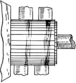
Fig. 716.--Rough and grooved commutator due to improper brush adjustment and failure to keep brushes in proper condition.
Ques. How is an untrue commutator detected?
Ans. If the commutator be untrue, the fact will be indicated when the machine is slowed down by a visible eccentricity, or by holding the hand, or a stick in the case of a high tension machine, against the surface while revolving, when any irregularity or eccentricity will be apparent by the vibration or movement of the stick. The only remedy for an untrue commutator is to re-turn it in the lathe.
[643] Ques. What should be done in case of high segments?
Ans. They should be gently tapped down with a mallet, and if possible the clamping cones at the commutator end should be tightened.
If it be impossible to hammer the segments down, they should be filed down to the same diameter as the rest of the commutator, or the commutator re-turned. For low segments, the only remedy is to pull out the segments, or turn commutator down to their level.
Ques. Explain the term "flats on the commutator."
Ans. This is the name given to a peculiar fault which develops on one or more segments of the commutator. It is not confined to dynamos of bad design or construction, but frequently appears on those of the highest class, and may be recognized as a "pitting" or "flattening" of one or more segments.
Ques. What is the effect of flats on the commutator?
Ans. Sparking at the brushes.
Ques. What are the causes which produce flats?
Ans. Periodical jumping of the brushes due to a bad state of the commutator, bad joint in the driving belt, a flaw, or a difference in the composition of the metal of the particular bar upon which it appears. But more frequently flats may be traced to a more or less developed fault, such as a break, either partial or complete, in the armature coil.
The break may occur either in the coil itself, or at the point where its ends make connection with the lug of the commutator, or at the point where the lug is soldered to the segment.
Ques. What should be done in case of flats?
Ans. The brushes should be examined to see if any periodical vibration take place. If such be the case, the cause should be removed, the flat carefully filed or turned out, and the brushes readjusted.
[644] If it be due to a difference in the composition of the metal of which the segment is made, the flat will exist as long as the particular segment is in use, and will need periodic attention.
With hard drawn copper or phosphor bronze segments, this fault is rarely due to this last mentioned cause. It is more frequently due to bad soldering, of the conductors to the lugs, or of the lugs to the segments. In all cases of flats, if the disconnection in the armature circuit be not complete, and cannot be readily located, the effect of re-soldering or sweating the ends of the coils into the lugs should be tried. Flats may also frequently be cured by drilling and tapping a small hole in the junction between the lug and the segment, and inserting a small screw, or bit of screwed copper or brass wire, afterwards filing down level with the surface of the commutator.
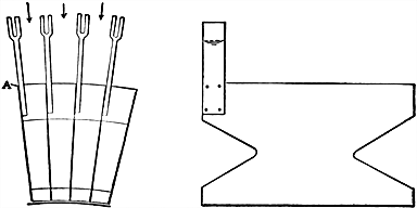
Figs. 717 and 718.--Method of repairing broken joint between commutator segment and lug. To repair such a break push asbestos in between adjacent bars, so that heat from the torch will not affect them. Asbestos should also be worked in at the back if possible, for the purpose of keeping solder from places where it would cause trouble. Then unsolder the armature leads from the lug and remove the latter. Next, with specially made cape chisels, cut in a slot in the commutator bar for a new lug. Care and skill are required not to destroy the mica insulation between the segments. The slot should be cut one-quarter to three-eighths inch deep. The connector is then soldered in place. With care a satisfactory connection can be made in this way, which will last well. If it do not last, the trouble in almost every case is due to poor soldering. Short circuits sometimes occur after this operation, because of solder falling in at the back and lodging on lower connections. In large machines, the excessive current flowing is quite likely to melt this solder, and the machine may buck, throwing out the melted solder, after which it may be all right again. While the bar connector is out, however, asbestos should be packed in back of it to prevent this occurrence, which may be a serious affair. All surplus solder and the asbestos packing should be removed after the connection is finished, and the connections cleaned with compressed air. The armature should be turned over slowly, air being applied all the while.
Segments Loose or Knocked In.--When the segments are loose, it is an indication that the clamping ring or cone has worked loose. This should therefore be tightened up, and the commutator re-turned if necessary.
[645] Ques. How should low commutator segments be treated?
Ans. The commutator surface may be turned down to the level of the low segment, or the latter may be pulled out again to its former level, this latter being the preferable method, if it can possibly be effected.
Ques. How is a commutator segment pulled out to its correct position?
Ans. A hand vise is firmly clamped to the lug, or a loop of copper wire is passed round the conductor where it joins the commutator. A bar of iron, to act as a lever, is supported on a fulcrum over the commutator, and one end of the bar is passed through the loop or vise. Pressure is applied to the other end which will generally bury the segment up to its proper position.
How to Re-turn a Commutator.--In re-turning the commutator, the armature should first be carefully taken out of the armature chamber, avoiding knocks or blows of any kind. The whole of the winding should then be wrapped in calico or canvas before the armature is put into the lathe, to prevent any particles of metal becoming attached to the surface of the armature at the time the commutator is being turned. The armature should on no account be rolled upon the floor, or subjected to blows or knocks while being put into the lathe.
In re-turning the commutator, a sharp pointed tool should be used with a very fine feed. A broad nosed tool ought not to be used, as it is liable to burr over the segments. After turning, the commutator should be lightly filed with a dead smooth file, and finally polished with coarse and fine sandpaper. After the commutator has been turned and polished, the insulation between the segments should be lightly scraped with the tang of a small file to remove any particles of metal or burrs which might short circuit the commutator.
[646] The points where the armature wires are soldered to the lugs should also be carefully cleaned with a brush, and should then receive a coat or two of shellac varnish.
While the commutator is being turned, care should be taken that the setting marks for the adjustment of the brushes are not turned out if these be present. The same care should be used in putting the armature back into the armature chamber as was used in taking it out, otherwise the insulation may be damaged.
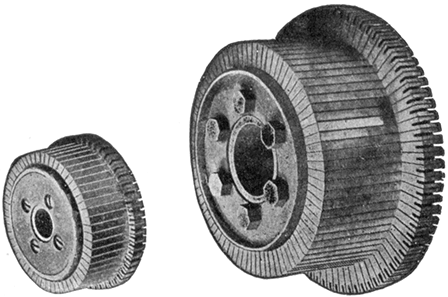
Figs. 719 and 720.--Bissell commutators. The segments are of hard drawn copper and are insulated from each other and from the shell by mica.
Ques. Should the commutator be run without any lubricant?
Ans. In most cases it will be found that a little lubricant is needed in order to prevent cutting the brushes, cutting the commutator; this is especially the case when hard strip brushes are used. The quantity of oil applied should be very small; a few drops smeared upon a piece of clean rag, and applied to the commutator while running, being quite sufficient.
Ques. What kind of oil should be used on the commutator?
Ans. Mineral oil, such as vaseline, or any other hydrocarbon. Animal or vegetable oils should be avoided, as they [647] have a tendency to carbonize, and thus cause short circuiting of the commutator, with attendant sparking.
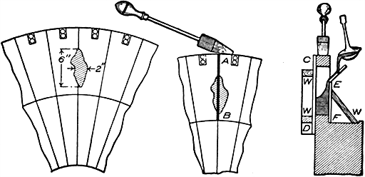
Figs. 721 to 723.--Method of repairing a large hole burned in two adjacent bars of a commutator. Fig. 721 shows the hole. The first operation is to clean carefully and tin the surface of the hole. The two bars are then wedged apart and mica strips, A B, fig 722, of the requisite size and thickness forced in. The commutator must now be warmed up as much as possible by means of soldering irons, and strips of mica, C D, E F, fig. 723, placed at the front and back of the hole, being kept in position by pieces of wood W, solder is poured into the hole from a ladle, using a rough mica funnel to guide it.
Overload of Dynamo.--It may happen, through some cause or other that a greater output is taken from the machine than it can safely carry. When this is the case, the fact is indicated by excessive sparking at the brushes, great heating of the armature and other parts of the dynamo, and possibly by the slipping of the belt (if it be a belt driven machine), resulting in a noise. The causes most likely to produce overload are:
Ques. What is the indication of excessive voltage?
Ans. It is indicated by the voltmeter, or by the brilliancy of the pilot lamp.
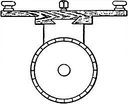
Fig. 724.--Method of smoothing commutator with a stone. The proper stone to use is made out of white sandstone similar to that used for grindstones, but a trifle softer. It is dove-tailed into a holder, as shown in the illustration, and held in place by a set screw. When being used, one knob is grasped in one hand and the other knob in the other hand, the stone being moved back and forth along the length of the commutator. As the stone will become coated with copper at first, it must be cleaned frequently by means of coarse sandpaper. The fine dust from the stone will get under the brushes and wear them to a very close fit. After using the stone, finish with fine sandpaper.
Ques. What are the causes of excessive voltage?
Ans. Over excitation of the field magnet or too high speed.
In the former case, resistance should be introduced into the field circuit to diminish the current flowing therein if a shunt machine; or if a series machine, a portion of the current should be shunted across the field coils by means of a resistance arranged in parallel with the series [649] coils; or the same effect may be produced in both cases by reducing the speed of the armature if this be possible.
If due to excessive speed, which will be indicated by a speed indicator, the natural remedy is to reduce the speed of the engine driving the dynamo, or, if this be not easily done, insert resistance into the dynamo circuit, as described above.
Ques. What are the causes of excessive current?
Ans. If the dynamo be supplying arc lamps, the excessive current may possibly be caused by the bad feeding of the lamps. If this be the case, the fact will be indicated by the oscillations of the ammeter needle, and the unsteadiness of the light.
If incandescent lamps be in the circuit, the fault may be caused by there being more lamps in circuit than the dynamo is designed to carry. Under such circumstances, another dynamo should be switched into circuit in parallel, or, if this be not possible, lamps should be switched off until the defect is remedied.
When motors are in the circuit, sparking frequently results at the dynamo commutator, owing to the fluctuating load. In such cases the brushes should be adjusted to a position at which the least sparking occurs with the average load.
Ques. What may be said with respect to reversal of polarity of dynamos?
Ans. When compound or series wound dynamos are running in parallel, their polarity is occasionally reversed while stopping by the current from the machines at work.
Loose Connections, Terminals, etc.--When any of the connecting cables, terminal screws, etc., securing the different circuits are loose, sparking at the brushes, as a rule, results, for the reason that the vibration of the machine tends to continually alter the resistance of the various circuits to which they are connected.
When the connections are excessively loose, sparking also results at their points of contact, and by this indication the [650] faulty connections may be readily detected. When this sparking at the contacts is absent, the whole of the connections should be carefully examined and tested.
Breaks in Armature Circuit.--If there be a broken circuit in the armature, as sometimes happens through a fracture of the armature connections, etc., there will be serious flashing or sparking at the brushes, which cannot be suppressed by adjusting the rocker. As a rule it results in the production of "flats" upon one or more bars of the commutator.
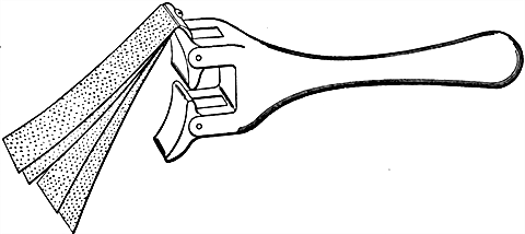
Fig. 725.--Sandpaper holder for commutator. The sandpaper is made fast on top by a clamp and screw. The two face blocks are pivoted and adjust themselves to the commutator, and will fit any size of commutator. If it have four brushes, the lower block will go in between the brush-holders.
Ques. How may such sparking be reduced without stopping the machine?
Ans. By placing one of the brushes of each set a little in advance of the others, so as to bridge the gap.
Short Circuits in Armature Circuit.--This fault is indicated by sparking at the commutator, and in bad cases by an excessive heating of the armature, dimming of the light and [651] slipping of the belt, and in the case of a drum armature, by a sudden cessation of the current.
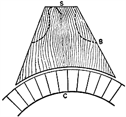
Fig. 726.--Sandpaper block. It is made to fit the surface of the commutator. At S is a saw cut into which the ends are pushed after being wrapped around the block. The latter should be cut down on the dotted lines to form a handle.
Short Circuits or Breaks in Field Magnet Circuit.--Either of these faults is liable to give rise to sparking at the commutator. If one of the coils be short circuited, the fact will be indicated by the faulty coil remaining cool while the perfect coil is overheated. The fault may arise through some of the connections to the coils making contact with the frame of the machine or with each other. To ascertain this, examine all the connections, and test with a battery and galvanometer. A total break in one or more of the field coils may readily be detected by means of the battery and galvanometer.
A partial break is not, however, so readily discovered, for the reason that the coil wires may be in sufficiently close contact to give a deflection of the galvanometer needle. The only methods of detecting this fault is by measuring the resistance of the coils with an ohmmeter or [652] Wheatstone bridge, or by placing an ammeter in circuit with each coil in turn, and comparing the amount of current flowing in each. If the partial break be not accessible, the only way to remedy the fault is to rewind the coil, and the same applies to a break in the interior of the coil.
Short Circuits in Commutator.--These are of frequent occurrence, and result in heating the armature and sparking at the brushes. They are caused either by metallic dust or particles lodging in the insulation between the segments, or by the deterioration of the commutator insulation.
To remedy, the insulation between the segments should be carefully examined, and any metallic dust, filings, or burrs cleaned or scraped out. When the commutator is insulated with asbestos or pasteboard (as is oftentimes the case in dynamos of European make), short circuits very frequently occur through the insulation absorbing moisture or oil, which is subsequently carbonized by the sparking at the brushes. In faults of this description the only remedy is to expel all moisture from the commutator insulation by means of heat, and scrape out all metallic dust which may be embedded in the surface of the insulation. If this do not effect a cure, it will be necessary to dig out the insulation, as far as possible, with a sharp tool, and drive in new insulation. Oil should not be used on commutators insulated with these materials, but only asbestos dust or French chalk.
The excessive heating of the parts of dynamos and motors is probably the most frequent and annoying fault which arises in operation. When the machine heats, it is a common mistake to suppose that any part found to be hot is the seat of the trouble. Hot bearings may cause the armature or commutator to heat, or vice versa.
All parts of the machine should be tested to ascertain which is the hottest, since heat generated in one part is rapidly diffused. This is best done by starting with the machine cold; any serious trouble from heating is usually perceptible after a run of a few minutes at full speed with the field magnets excited.
Heating may be due to various electrical or mechanical causes, and it may occur in the different parts of the machine, as in:
Ques. How is heating detected?
Ans. By applying the hand to the different parts of the machine if low tension, or a thermometer if high tension, and also by a smell of overheated insulation, paint, or varnish.
[654] Ques. What should be done if the odor of overheated insulation, paint or varnish be noticeable?
Ans. It is advisable to stop the machine at once, otherwise the insulation is liable to be destroyed.
Ques. What is the allowable rise of temperature in a well designed machine?
Ans. It should not exceed 80° Fahr., above the surrounding air, and in the case of the bearings, this temperature ought not to be reached under normal conditions of working.
If this limit be exceeded after a run of six hours or less, it indicates a machine either badly designed and probably with the material cut down to the lowest possible limit with a view to cheapness, or some fault or other which should be searched for and remedied as early as possible, otherwise the machine will probably be destroyed.
Ques. How should the rise of temperature be measured?
Ans. It is not sufficient to feel the machine with the hand, but special thermometers must be placed on the armature winding, immediately on stopping the machine, covering them with cotton or wool to prevent cooling. Readings must be taken at short intervals, and continued till no further rise of temperature is indicated.
Heating of Connections.--A rise of temperature of the connections may be due to either excessive current, or bad contacts, or both. The terminals and connections will be excessively heated if a larger current pass through them than they are designed to carry. This nearly always proceeds from an overload of the dynamo, and if this be rectified, the heating will disappear.
If the contacts of the different connections of the dynamo be not kept thoroughly clean and free from all grit, oil, etc., and the connections themselves be not tightly screwed up, heating will result, and the connections may even become unsoldered.
[655] Heating of Brushes, Commutator and Armature.--When heating occurs in these parts, it may be due to any of the following causes: 1, excessive current; 2, hot bearings; 3, short circuits in armature or commutator; 4, moisture in armature coils; 5, breaks in armature coils; 6, eddy currents in armature core or conductor.
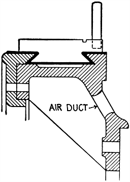
Fig. 727.--Ventilated commutator; sectional view showing air ducts. Air is frequently circulated through a commutator in order to maintain it at a sufficiently low temperature, suitable openings being provided for this purpose as shown.
Ques. What may be said with respect to excessive current?
Ans. When a dynamo is overloaded, the temperature of the armature will rise to a dangerous extent, depending upon the degree to which the safe capacity of the machine is exceeded, and heavy sparking of the brushes will also result. If the overload be not removed, the insulation of the armature may be destroyed.
Ques. State some causes of hot bearings.
Ans. Lack of oil; presence of grit or other foreign matter in the bearings; belt too tight; armature not centred with respect to pole pieces; bearings too tight; bearings not in line; shaft rough or cut.
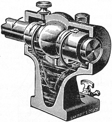
Fig. 728.--Self-oiling and self-aligning bearing. The self-oiling feature consists of rings which revolve with the shaft, and feed the latter with oil continually, which they bring up from the reservoir below. The dirt settles to the bottom, and the upper portion of the oil remains sufficiently clean for a long time, after which it is drawn off, and a fresh supply poured in through holes provided in the top. These latter are often located directly over the slots in which the rings are placed, so that the bearings can be lubricated immediately by means of an oil cup if the rings fail to act or the reservoir become exhausted. The bearing is made self-aligning by providing the bearing proper with an enlarged central portion of spherical shape, held in a spherical seat formed in the pedestal by turning, milling, or by casting Babbitt or other fusible metal around it, thus allowing the bearing to adjust itself to the exact direction of the shaft. The upper half of the box can be taken off to facilitate renewal, etc., and to permit the armature to be removed.
Ques. What is the effect of hot bearings?
Ans. Besides giving trouble themselves, the heat may be conducted along the armature shaft and core, thus giving rise to excessive heating of the armature.
[657] POINTS RELATING TO HOT BEARINGS
Ques. What troubles are encountered with short circuits in the armature or commutator?
Ans. This results in sparking at the brushes, and in the heating of one or more of the armature coils, and even in the burning up of the latter if a bad case.
When the armature is overheated, and the defect does not proceed from an overload or the causes mentioned below, the dynamo should be immediately stopped and tested for this fault.
Ques. What will happen with an overheated commutator?
Ans. It will decompose carbon brushes and cover the commutator with a black film, which offers resistance and increases the heat.
Ques. What should be done if carbon brushes become hotter than the other parts?
Ans. Use higher conductivity carbon. Reduce length of brush by adjusting holder to grip brush nearer the commutator. Reinforce brushes with copper gauze, sheet copper or wires, or use some form of combined metal and carbon brush. Increase size or number of brush if necessary, so the current does not exceed 30 amperes per square inch of contact.
[658] Brushes heat sometimes due to too much friction. They should not press against the commutator more than is necessary for good contact.
Ques. Give some causes for heating of armature.
Ans. Eddy currents; moisture; short circuits; unequal strength of magnetic poles; operation above rated voltage, and below normal speed.
Ques. What trouble is encountered with eddy currents?
Ans. Considerable heating of the whole of the armature results, which may even extend to the bearings.
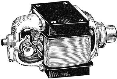
Fig. 729.--Eck Manchester type motor. It is a very small size unit and is designed for special purposes where very little room is available. The motor occupies a space of 2-1/2" × 4-3/8" between bearings and develops 1/16 horse power at 2,000 R. P. M. The frame of this motor is made of high permeability steel so as to reduce the weight to a minimum. The armature is of the hand wound bipolar type built up of thin punchings. The armature, after being wound, is baked at high temperature for a prolonged period and then dipped while hot in insulating varnish. Pulley is one inch in diameter and takes a 1/4 inch round belt. Weight of motor 5-1/2 pounds.
Ques. How can this be overcome?
Ans. There is no remedy for eddy currents other than the purchase of a new armature, or reconstruction.
The fault may be detected by exciting the field magnets and running the machine on open circuit, with the brushes raised off the commutator for some time, when the armature will be found to be excessively heated.
[659] Ques. How does moisture in the armature coils affect the armature?
Ans. The effect of this fault being to practically short circuit the armature, a heating of the latter results. In bad cases, steam or vapor is given off.
Ques. What is the effect of short circuits in the armature?
Ans. It produces overheating.
Ques. What trouble is likely to occur when the armature is not centered in the armature chamber?
Ans. A heating of the bearings is liable to be occasioned through the attractive forces developed by the center of the armature core not being parallel with the centre of the armature chamber or bore, or through the core being nearer one pole piece than the other.
This may result from unequal wearing of the bearings, and therefore the bearings should either be relined or the bolt holes of the bearings readjusted, or the bearings packed up until the armature is correctly centered.
Ques. What happens in case of breaks in the armature coils?
Ans. This fault results in local heating of the armature, for the reason that resistance is interposed in the path of the current at the fracture. It always results in sparking at the brushes, and the heating being confined to the neighborhood of the break.
Ques. What are the effects of operation above the rated voltage and below normal speed?
Ans. Voltage above normal is a possible cause of heating, and operation below normal speed calls for an increase of field strength and reduces the effective ventilation, thus tending to cause heating.
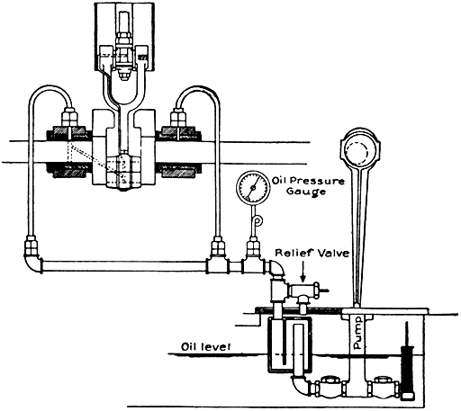
Fig. 730.--Forced system of lubrication as applied to engine of the generating set shown in fig. 443. In engines employing the forced system of lubrication the crank pit, which is formed by the columns, is accessible through doors in the front and back of the engine. The base of the engine forms an oil tank to which is attached a small plunger pump driven by an eccentric on the shaft. The lubricant is carried under pressure to the various parts of the engine by the mechanism shown in the accompanying diagram. The oil is forced by a pump to a groove in the main bearing, and a drilled hole in the shaft connects this groove with the crank pin. From the crank pin box the oil is further forced to the wrist pin through the pipe running along the side of the connecting rod. The passage in the crosshead allows the oil to be forced from the wrist pin to the guides. As the oil is forced from one bearing to another, it is quite important that the bearing caps be set tight, otherwise the oil will escape before reaching the last bearing. After passing through the bearings, the oil is collected in the base, strained and used again. The oil should be free from foreign substances, and to guard against the introduction of any foreign matter, a strainer, which may be taken out for examination or cleaning, is attached to the suction valve of the pump. An oil pressure of from 10 to 20 lbs. should be maintained, and may be regulated by adjusting the set screw on the relief valve of the oiling system. The pressure gauge need not remain in the circuit continuously. Only mineral oils should be used for lubrication. A heavy oil gives better results and prevents knocking more effectively than thin oil. An oil which has been found to give good results, consists of two-thirds red engine oil and one-third heavy cylinder oil. As the oil passes through the bearings repeatedly, it gradually loses its lubricating properties, becoming thick and gritty, and should be occasionally run through a filter and mixed with new oil. The frequency of this change depends on the oil, as well as the number of hours the engine is in operation, and can easily be determined by observation. The oil in the reservoir should stand about 2 inches over the suction and discharge valves, and no water should be allowed to mix with it. Should any water accumulate in the base, it should be drawn off by the cock provided for the purpose before starting the engine.
[661] Ques. How may the field magnets become heated?
Ans. By excessive field current; eddy current in pole pieces; moisture; short circuits.
Ques. What may be said with respect to excessive field current?
Ans. When heating results from this cause, all the exciting coils will be heated equally. It may be due to excessive voltage, in the case of shunt dynamos; or to an overload in the case of compound and series dynamos. In either case it may be remedied by reducing the voltage or overload. If due to the coils being incorrectly coupled up, that is, coupled up in parallel instead of in series, it will be necessary to rectify the connections or insert a resistance in series.
Ques. State the causes of eddy currents in the pole pieces?
Ans. This fault may be due to defective design or construction of the armature. Slotted armatures are particularly liable to cause this fault, if the teeth and air gap be not properly proportioned. The defect may also be occasioned by variation in the strength of the exciting current.
If due to this latter cause, it will be accompanied by sparking at the brushes. If a shunt dynamo, insert an ammeter into the shunt circuit, and note if the deflection be steady. If this be not the case, the variation in the current most probably proceeds from imperfect contacts thrown into vibration.
Ques. How is the insulation affected by moisture?
Ans. Moisture tends to decrease the insulation resistance, thus in effect producing a short circuit with its attendant heating.
Ques. How is moisture in the field coils detected?
Ans. It is easily detected by applying the hand to the coils, [662] when they will be found to be damp, and in addition steam or vapor will be given off where the machine is working.
The fault may be remedied by drying and varnishing the coils.
Ques. What is the indication of short circuits in the field coils?
Ans. This fault is characterized by an unequal heating of the field coils. If the coils be connected in series, the faulty coil will be heated to a less extent than the perfect coils; if connected in parallel, the faulty coil will be heated to a greater extent than the perfect coils. The former can thus be easily located.
In operating motors of any considerable size, whether connected to the public supply mains of a central generating station for combined lighting and power service, or to power service mains only, there are certain precautions to be observed in starting, stopping, and regulating the motor, in order that the efficiency of the supply, and indirectly the working of other motors and lamps connected to the mains in the immediate neighborhood, may not be affected by abnormal variations of pressure. These precautions should be observed also to prevent any danger of the motor itself being subjected to detrimental mechanical shocks and excessive temperatures in the working parts.
Before Starting a Motor.--The general instructions relating to inspection and adjustment, lubrication, etc., which have already been given, should be carefully followed preparatory to startingE.
[E] NOTE.--In starting a motor, first see that the bearings contain sufficient oil and that the brushes bear evenly on the commutator. If a circuit breaker be used, close it; then close the main switch. Rotate slowly the handle of the starting rheostat as far as it will go. Care should be taken, in starting the motor, that the handle of the rheostat be not rotated too fast. To stop a motor, open the circuit breaker or switch, which will cut in the resistance of the starting box. Never attempt to stop a motor by forcibly pulling open the starting box, Disregard of these instructions may cause burning out of the field coils.
Starting a Motor.--In starting a motor, resistance must be put in series with the armature because, since there is no reverse electromotive force to counteract the applied voltage when the motor is at rest, the switching of the latter direct to the motor would result in an abnormal rush of current. This, in addition to being uneconomical and productive of a drop of voltage in [664] the mains, would injure all except the smallest motors. Hence motors above two horse power usually require a rheostat.
Ques. Describe a rheostat or "starting box."
Ans. It consists essentially of a suitable resistance to be inserted at starting to reduce the initial rush of current, and which can be cut out in sections by successive movements of a lever as the speed increases.
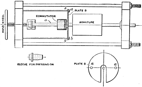
Fig. 731.--Press for forcing on and removing a commutator. Small commutators are pressed on to the shaft by a hand press. All of the larger commutators are pressed on by means of a power press. In the above figure is shown a hand press. The plate B is used in removing old commutators. It is placed back of the commutator as at x y with the slot C over the shaft. Bolts a b are passed through the holes in the plate and secured by nuts. The commutator can then be forced off the shaft. In pressing on a commutator, a sleeve is placed over the shaft at O, and against the commutator. The rear end of the shaft is secured so it will withstand the pressure, and the commutator is forced on. The power presses are built on the principle of a hydraulic press. In pressing on a commutator a piece of babbitt metal or soft brass should be used against the end of the shaft. The shaft should be painted with white lead before having the commutator pressed on, in order to lubricate the shaft so that the commutator will press on easily. The wiper rings are pressed on after the commutator and then the armature is ready to be connected.
Ques. Describe what occurs in starting a motor.
Ans. When the lever of the starting box is moved to the first contact some of the resistance is cut out of the circuit and current flows through the motor. This produces a torque and starts the armature rotating. The movement of the armature induces a reverse voltage, which, as the speed increases, gradually reduces [665] the applied current. With this reduction of current, the torque is reduced and the speed not accelerated as quickly as at first. When the applied current has been reduced to a certain value by the increasing reverse current, the handle of the starting box is moved to the next contact, and so on till all the resistance in the starting box has been cut out, the motor then attaining its normal speed.
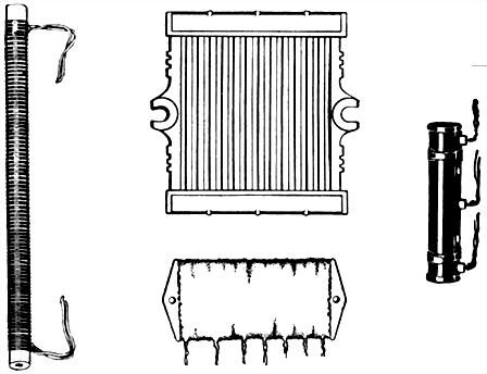
Figs. 732 to 735.--Various starting resistances. The type of resistance used in motor starting rheostats of small size consists usually of tinned iron wire wound on asbestos tubes, as shown in fig. 732, the tubes being firmly supported by porcelain nipples, the ends of which fit into holes in the top and bottom of the enclosing case. In starters of larger size, cast metal grids, as shown in fig. 733, are used. In addition to these types of resistance, some forms of starter are equipped with what is known as "unit" type resistance. In this form, the resistance is built up of a number of separate sections, or units, which are connected to form the complete starting or regulating resistance as the case may be. A single unit consists of a moulded core of vitreous material upon which is wound the resistance wire, as shown in fig. 734. The surface of the unit is then coated with a special cement and baked. By this method the resistance material is protected from mechanical injury and is also made proof against moisture and other conditions which sometimes affect the ordinary type of resistance. In addition to units coated with cement only, there are still other types of units, as in fig. 735, which are provided with a sheet metal covering around the cement, as a further precaution against injury. Each of the various types of resistance described possesses certain characteristics not shared by the others, the use of any particular type being largely governed by conditions of service.
Ques. What is the difference between a starting box and a speed regulator?
Ans. Motor starting rheostats or "starting boxes," are [666] designed to start a motor and bring it gradually from rest to full speed. They are not intended to regulate the speed and must not be used for such purpose.
Failure to observe this caution will result in burning out the resistance which, in a motor starter, is sufficient to carry the current for a limited time only, whereas in the case of speed regulators sufficient resistance is provided to carry the full load current continuously.
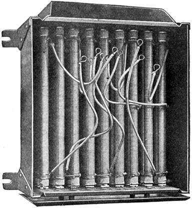
Fig. 736.--View of Cutler-Hammer starter with slate front removed showing open wire coil resistance. The type of resistance here used consists of tinned iron wire wound on asbestos tubes. The bottom of the casing is perforated to secure ventilation.
Ques. For what kinds of service are speed regulators used?
Ans. In cases when the speed must be varied, as in traction motors, organ blowers, machine tool drive, etc.
Ques. How long does it take to start a motor?
Ans. Usually from five to ten seconds.
[667] Ques. How is the starting lever operated?
Ans. It is moved progressively from contact to contact, pausing long enough on each contact for the motor to accelerate its speed before passing to the next.
Ques. What are the conditions at starting in a series motor?
Ans. There is a rush of current, the magnitude of which depends on the amount of resistance cut out at each movement of the starting lever.
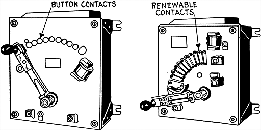
Figs. 737 and 738.--Sliding contact starters. Fig. 737, starter with button contacts; fig. 738, starter with renewable contacts. Motor starters in which the successive steps of resistance are cut out by a pivoted lever carrying a contact shoe which slides over button contacts or over contact segments, are known as sliding contact starters. Button contacts are usually furnished with motor starting rheostats of small size while contact segments are used on those of greater capacity. The contact segment being held in position by two screws, is readily renewable when worn by long service or damaged by arcing. The fixed button contact is not so easily renewed but being used only on small size starters is never likely to be subjected to severe service. Some starters, however, have renewable button contacts.
Ques. How are small series motors started on battery circuits?
Ans. By simply closing a switch to complete the circuit, the resistance of the battery being sufficient to prevent a great rush of current while starting.
[668] Ques. How is a shunt motor started?
Ans. In starting a shunt motor, no trouble is likely to occur in connecting the field coils to the circuit. Since the resistance of the armature is very low, it is necessary on constant voltage circuits to use a starting rheostat in series with the armature.
The necessary connections are shown in fig. 756. The switch is first closed thus sending current through the field coils, before any passes through the armature. The rheostat lever P is then moved to the first contact to allow a moderate amount of current to pass through the armature. The resistance of the rheostat is gradually cut out by further movement of the lever P, thus bringing the motor up to speed.
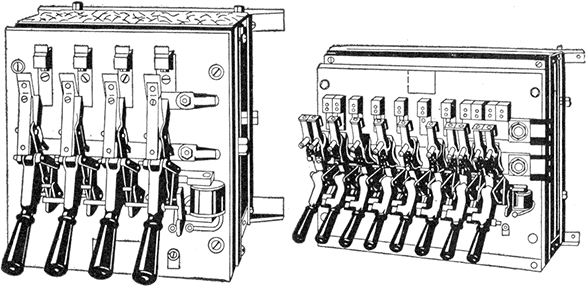
Figs. 739 and 740.--Multiple switch starters. Fig. 739, starter with no voltage release; fig. 740, starter with no voltage release and circuit breaker. The multiple switch type of starter is designed to overcome the arcing on sliding contacts which, in the case of large motors would be very severe. The cutting out of each step of resistance is accomplished in the multiple switch starter by a separate carbon contact switch which breaks the circuit with a quick snappy action.
Ques. How does the reverse voltage affect the starting of a motor?
Ans. When a motor is standing still, there is no reverse voltage, and the current taken at first is governed principally by the resistance of the circuit. If the motor be series wound, there is a momentary reverse voltage, due to self-induction while [669] the field is building up. If the motor be shunt wound, self-induction delays the current through the field coils, but that through the armature is not impeded by such cause. When the armature begins to revolve, reverse voltage is developed which increases with the speed. The resistance of the starting box may be gradually cut out as the armature comes to speed. Thus the reverse voltage gradually replaces ohmic drop in limiting the current as the motor comes to speed.
Fig. 741.--Starting rheostat with no voltage and overload release. The no voltage release permits the starting lever to fly to the "off position" should the voltage fail momentarily, thus protecting the motor against damage should the voltage suddenly return to the line. The movement of the lever is due to a spring. The overload device causes the lever to back to the off position should the current exceed a predetermined maximum for which the release is adjusted.
Fig. 742.--Compound starter. Rheostats designed for the double duty of starting a motor and regulating its speed are commonly known as compound starters, the resistance provided being a combination of armature resistance for starting duty and shunt field resistance for speed regulation.
Failure to Start.--This fault, which is liable to occur in a motor of any description, is similar to failure to excite in a dynamo, and is liable to be produced by any of the causes mentioned in connection with the latter fault, excluding insufficient speed, and insufficient residual magnetism.
When a motor fails to start, it should first be ascertained if a supply of electrical energy be available in the [670] mains. This may readily be discovered by means of a voltmeter, or if low tension service, by means of the fingers bridging across the main terminals. If the supply of energy be present, the contact arm of the starter should be moved into such position that all resistance is inserted into circuit with the motor. This is important, as the motor may start suddenly while trying to ascertain the cause of the stoppage.
Fig. 743.--Starting panel. In installing any kind of motor starting rheostat, it is necessary to provide main line knife switch and fuses in addition to the starting box. The appearance of the installation can be much improved by mounting all of these upon one panel.
Having closed the switch, if the motor fail to start, it will be advisable to remove the load if possible, as the failure may arise from an overload of the machine. This being effected and the motor not starting, the terminals of the latter should be tested by the means already described for voltage. If no voltage be [671] generated, a broken circuit or a defective contact may be looked for in the main fuse, switch, or starting box. The resistance coils of the latter, through the heat developed, frequently break in positions out of sight. If a defective contact of this nature cannot readily be seen, the contact arm should be moved slowly over the contacts, as it is possible the broken coil may be cut out of circuit by this means.
Figs. 744 to 746.--Cutler-Hammer motor starting rheostats with no voltage and overload release. Fig. 744, starter with fixed button contact, fig. 745, with renewable button contact, and fig. 746, with contact segments. In construction the resistance is enclosed in a pressed steel box on which is mounted a marbleized slate panel carrying the starting lever, contacts and protective devices. By means of a calibrated scale, the overload release (shown in the lower left hand corner, figs. 744 and 745, and in the lower right hand corner fig. 746) can be set to break the circuit on any overload not exceeding 50 per cent. of the rated capacity of the motor. This calibrated scale can also be used for determining, with a fair degree of accuracy, the amount of current being consumed by the motor.
If a difference of pressure exist between the motor terminals, the field magnets will, if shunt or compound wound and in good order, be excited, which may be ascertained by means of a bar of iron. If no magnetism be present, it will of course, indicate a broken or bad connection, either between the terminals of the field coils, or one or more of the coils themselves. If the bar pull strongly, the position of the brushes upon the commutator in regard to the neutral points should be ascertained, and the rocker adjusted, if necessary, to bring them into their correct positions. If this fail to start the motor, the connecting leads from the motor terminals to the brushes and the brushes themselves should be carefully examined for broken or bad connections, and defective contact of the [672] brushes with the commutator. In the latter case, it may arise from a dirty state of the commutator, or from the brushes not being fed properly. If due to these causes, pressing the brushes down upon the commutator with the fingers will probably start the motor. If the failure to start arise from none of these causes, it is probably due to the field coils acting in opposition, or to a short circuited armature. This latter remark applies more especially to motors provided with drum armatures.
Fig. 747.--Allen-Bradley compression type resistance units. The contact resistance between the discs composing the resistance column is subject to variations of pressure thereby producing proportionate resistance changes in the column as a whole. In the complete resistance unit, the resistances column is encased in a drawn steel tube, which is lined with a highly refractory cement, for purpose of insulation, affording the column both mechanical and electrical protection and excluding the air which effectually prevents any combustion should the column become red hot due to overload. The ends of the tube are closed by means of caps through which pass electrodes for making connections between the discs and exterior conductors. The steel tube, when necessary, is provided with ribs or fins for the dissipation of acquired heat.
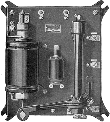
Fig. 748.--Allen-Bradley type Z automatic motor starter. The operation of this machine is as follows: When the main switch is closed, the motor circuit is made through the fuses, resistance unit, current relay, and the motor armature. At the same time, the solenoid circuit is closed (this is connected directly across the line, and takes a current which is a small fraction of an ampere), and the plunger of the solenoid is drawn up, which produces a pressure on the resistance unit, and increases the current in the motor circuit to the predetermined value at which the current relay is set. When this value is reached the current relay operates and opens the solenoid circuit, which reduces the magnetic pull and allows the solenoid plunger to drop back slightly. This action increases the resistance in the motor circuit, which decreases the current sufficiently to allow the relay to close again. Similar cycles of operation are repeated as the motor accelerates, and each time the plunger is drawn a little farther into the solenoid, until the short circuiting contacts on the top are pushed together, which short circuits the current relay and resistance unit, making them inoperative, and completing the operation of starting the motor. It will be noted that in starting a motor with this device the current is always held down to a certain predetermined value, and it is impossible to overload the motor by too rapid starting. The current relay is calibrated in amperes, and may be set to suit existing conditions. The action of the starter being controlled by a current relay and not by an oil or air dash pot, the motor will start rapidly when under a light load, and slowly when more heavily loaded. The fuses or circuit breakers may be set at a value that will furnish protection to the motor under running conditions.
Precautions with Shunt Motors.--With motors of this type, because of the large amount of self-induction in the shunt windings, it is important to note: 1, that in switching on the field magnet, the current may take an appreciable time to grow to its [674] normal value, and 2, that in switching off, especially with quick break switches, high voltages are induced in the windings, which may break down the insulation.
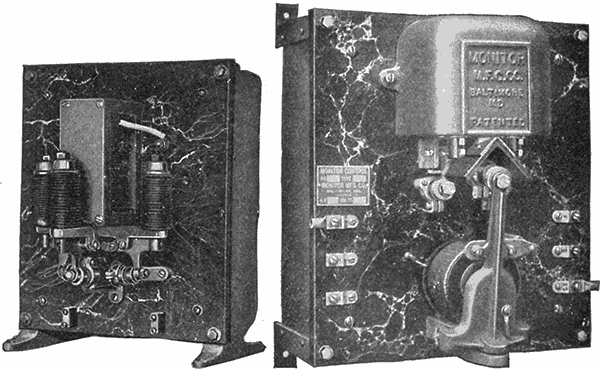
Fig. 749.--Monitor starter giving automatic start with knife switch control; designed for use with printing presses. It consists of a set of solenoids connected in series and so interoperating as to cut resistance out of the armature circuit of the motor as the apparatus it is driving comes up to speed. This type is for small motors or where no need arises for speed regulation; there is, therefore, no adjustment of speed possible aside from an actual change in motor conditions. At full speed the motor is directly across the main supply line.
Fig. 750.--Monitor automatic starter, equipped with relay for push button control.
Ques. What provision is made so that the magnetizing current will have time to reach its normal value?
Ans. The field connections are generally separated from the actual starter, and taken to the main switch, so that wherever the main switch is closed, the current flows through the field coils, before the starting lever is moved.
[675] Ques. How are the connections arranged to avoid excessive voltage in the windings due to self-induction?
Ans. Generally the armature and field magnet circuits are placed in a closed circuit that is never opened.
In other cases, in order that the rise of voltage may not injure the insulation when the shunt is opened, a special form of main switch is sometimes used which, before breaking from the supply, puts a non-inductive resistance across the shunt of the motor. This is known as a flashing resistance.
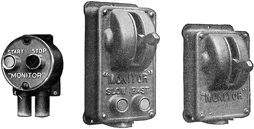
Figs. 751 to 753.--Monitor control switches. Fig. 751, push button "start" and "stop" switch; fig. 752, safety lever control switch with "slow" and "fast" buttons for rotary printing presses. This device will upon pressure of the "start" button, set the machine in motion and bring it up to the predetermined speed, either as previously set by the starter limits or by the setting of the rheostat arm. The stop button projects some distance beyond any other portion of the device, in order that in case of emergency the operator may stop the machine merely by hitting the face of the switch with his open hand. The lever control switch, fig. 753, is similar in its action to the push button switch but combines two other features: locking point, and visual indication of the station from whence the press has been stopped. With the lever at the downward position, the press is locked and cannot be started from any other station. In order to make the press ready to start the lever must be raised to the central position. Thus a man may safely enter the press without delay by setting his station to the locked position, knowing that it cannot be started except by some one coming to that station and realizing that the press has been purposely locked. Also, by looking along the press, it is possible to tell from which station it has been locked, and proper action can be immediately taken. The safety control station is usually combined for use on large rotary presses with the "slow" and "fast" push buttons as shown in fig. 752. A pressure upon the fast or slow buttons will cause the press speed to be correspondingly accelerated or retarded, and this action will continue so long as the button is pressed. The press continues to run at the speed attained at the instant of releasing the button. Any speed may, therefore, be selected or changed to suit momentary requirements. This gives complete control excepting reversal which is not required of such a press.
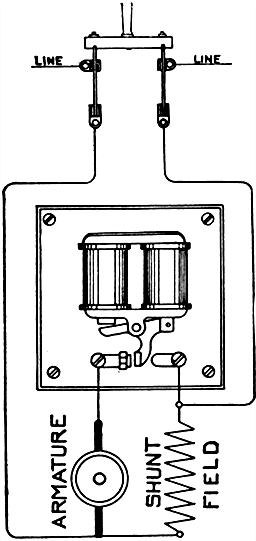
Fig. 754.--Wiring diagram of the standard form of Monitor controller. A set of solenoids are connected in series and so interoperating as to cut resistance out of the armature circuit of the motor as the apparatus it is driving comes up to speed. The controller is designed to be used on all classes of work. In its simplest form, a single copper and graphite contact, is controlled by two magnets, so proportioned as to cut out the entire starting resistance when the armature current falls to a predetermined value. In the larger sizes, the number of steps controlling the resistance is increased and arranged to produce the correct acceleration. In every case the regulation of the starting resistance is effected entirely by the current passing to the motor without the use of dash pot, mechanical governor or delicate cut outs. The time element is thus directly proportioned to the load and the motor brought up to speed in the shortest time consistent with the load, but always with safe limitation of the armature current. The distinction between the current controlled starter and the starter with dash pot governor should be noted. The starter here shown limits the starting current to a fixed value throughout the starting operation, which is an ideal condition and prevents blowing fuses in starting.
[677] Ques. How can shunt motors be controlled from a distant point?
Ans. The starter and switch are placed at the desired point and the two main wires and the field wires run from that point to the motor.
This requires additional wire which increases the cost and line loss.
Regulation of Motor Speed.--Motors are generally run on constant voltage circuits. Under these conditions, the speed of series motors varies with the load and at light loads becomes excessive. Shunt motors run at nearly constant speeds.
For many purposes, particularly for traction, and for driving tools, it is desirable to have speed regulation, so that motors running on constant voltage circuits may be made to run at different speeds.
The following two methods are generally used for regulating the speed of motors operated on constant voltage circuits:
1. By inserting resistance in the armature circuit of a shunt wound motor;
2. By varying the field strength of series motors by switching sections of the field coils in or out of circuit.
Ques. Describe the first method.
Ans. This method is illustrated in fig. 756. When the main switch is closed, the field becomes excited, then by moving the lever P of the starting rheostat the various contacts (1, 2, 3, 4, 5), more or less of the rheostat resistance is cut out of the armature circuit, thus varying the speed correspondingly.
This is the same as the method of starting a motor, that is, by variation of resistance in armature circuit, but it should be noted that when this method is used for speed regulation, a speed regulating rheostat should be used instead of the ordinary starting box, because the latter, not being designed for the purpose, will overheat and probably burn out.
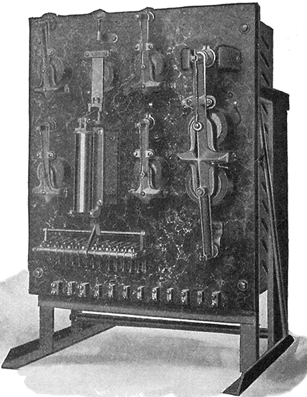
Fig. 755.--Monitor printing press controller. It provides variable speed and other control features required in the operation of large rotary presses, such as those used for printing newspapers. From any one of various stations similar to the one illustrated in fig. 753, located at all desirable places about the press, the latter may be started, stopped, accelerated, slowed down or locked. It differs from other types of printing press controller in that the solenoid has an overall maximum pull of less than one inch and does not actuate the main line current directly but through pilot circuits, which in turn, operate flapper switches; there are no sliding contacts. At the control stations, the operator can distinguish the accelerating button from the retarding button by the sense of touch and obviously he can in the same manner ascertain the position of the lever. The position of the lever whether at start, stop or safety, can be readily observed at a distance. When the lever of either control station is placed at stop, the current is disconnected from the motor and a powerful dynamic brake brings the press to rest without delay and without shock or harmful strain. The start will always be made with all resistance in the armature circuit, and with full field, and should the current supply fail, the controller will release and open the circuit to the motor. This controller will give a speed range as low as 10% of normal speed by armature resistance and, by field control, any increase within the speed of the motor.
[679] Ques. Describe the second method.
Ans. This method of regulating the speed of a series motor is shown in fig. 757. The current through the armature will flow through all the field windings when the position of the switch lever S, is on contact 4, and the strength of the field will be the maximum. By moving the arm to contact 3, 2, etc., sections of the field winding are cut out, thus reducing the strength of field and varying the speed.
Ques. How does the speed vary with respect to variation of field strength?
Ans. Decreasing the field strength of a motor increases its speed, while increasing the field strength decreases the speed.
Under the conditions of maximum field strength, as with switch S on point 1, the torque will be greatest for any given current strength and the reverse voltage also greatest at any given speed. The current through the armature of the motor, to perform any given work, will thus be a minimum, as well as the speed at which the motor has to run, in order to develop sufficient reverse voltage to permit this current to flow. Regulation of speed by varying the field strength is limited in range of action, since the field saturation point is soon reached, moreover, with too low a field strength, armature reaction produces excessive field distortion, sparking, etc.
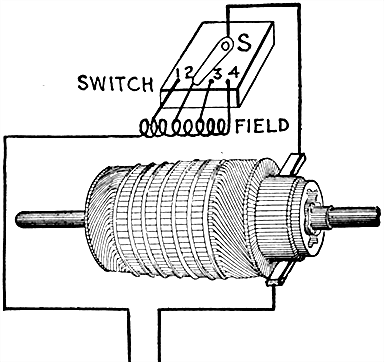
Fig. 757.--Speed regulation of series motor by cutting out sections of the field winding. In this method the field winding is tapped at several points, dividing the coil into sections and the leads from these points are connected a multi-point switch of the type that would be used on a rheostat. By moving the lever S, to the left or right, the current will flow through one or more sections of the field winding, thus decreasing or increasing the ampere turns and thereby providing means of regulation.
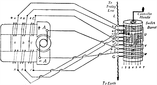
Fig. 758.--Speed regulation of a series motor by the method of short circuiting sections of the field winding. It will be seen that there are seven different positions for the contact springs on the barrel contacts. A. represents the armature and brushes, little A, B, and C, the divided field magnet coils, L the line connection, and G the earth connection. The diagram shows the connections for trolley car operation.
Ques. How is the speed of shunt and compound motors varied with respect to the normal speed in the two methods?
Ans. The first method (variable resistance in armature circuit) reduces the speed below the normal or rated speed of the machine, while the second method increases the speed above the normal.
In the first method the amount of speed reduction depends partly upon the amount of resistance introduced into the armature circuit, and partly upon the load.
In the second method the amount of speed increase depends entirely upon the amount of resistance placed in the shunt winding circuit.
[682] Eighty-five per cent. is about the maximum speed reduction obtainable by armature resistance but so great a reduction is seldom satisfactory since comparatively slight increases in the load will cause the motor to stall.
Shunt field regulation may be obtained up to any point for which the motor is suited, the only limitation in this case being the maximum speed at which the motor may be safely operated.
It should be remembered, however, that speed increase by shunt field weakening increases the current in proportion to the increase in speed, and care should be taken not to overload the armature.
NOTE.--A compound motor may be made to run at constant speed, if the current in the series winding of the field be arranged to act in opposition to that of the shunt winding. In such case, an increase of load will weaken the fields and allow more current to flow through the armature without decreasing the speed of the armature, as would be necessary in a shunt motor. Such motors, however, are not very often used, since an overload would weaken the fields too much and cause trouble. If the current in the series field act in the same direction as that in the shunt fields, the motor will slow up some when a heavy load comes on, but will take care of the load without much trouble.
NOTE.--Motors have much the same faults as dynamos, but they make themselves manifest in a different way. An open field circuit will prevent the motor starting, and will cause the melting of fuses or burning out of the armature. A short circuit in the fields, if it cut out only a part of the winding, will cause the motor to run faster and very likely spark badly. If the brushes be not set exactly opposite each other, there will also be bad sparking. If they be not at the neutral point, the motor will spark badly. Brushes should always be set at the point of least sparking. If it become necessary to open the field circuit, it should be done slowly, letting the arc gradually die out. A quick break of a circuit in connection with any dynamo, or motor is not advisable, as it is very likely to break down the insulation of the machine. The ordinary starting box for motors is wound with comparatively fine wire and will get very hot if left in circuit long. The movement of the arm from the first to the last point should not occupy more than thirty seconds and if the armature do not begin to move at the first point, the arm should be thrown back and the trouble located.
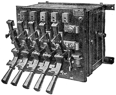
Fig. 759.--Cutler-Hammer multiple switch starter with no voltage release; for use with large motors, or with motors of medium size where the starting conditions are severe or when more than fifteen seconds are required to accelerate the motor. In operation, the cutting out of each step of resistance is accomplished by a separate lever and the levers themselves are so interlocked as to prevent closing switches except in proper order, beginning with the lever on the left. The last switch (the one on right hand side) is held by an electro-magnet when closed, each of the other switches being held in the closed position by a latching device on the switch next to it. In front of each switch is placed a metal stop, so arranged as to prevent any switch being operated until the one next to it on the left has been closed. These metal stops constitute the interlocking mechanism and prevent the starting of the motor in any way except by closing the switches in regular rotation, thus insuring proper resistance in the circuit and protecting the motor from excessive starting currents. When the current is interrupted, the electro-magnet releases the last switch, which, on opening, releases the latch on the switch next to it, allowing that switch to open, and this in turn releases the next latch and so on, the switches opening automatically one after another. In starting the motor, each switch should be closed quickly and firmly, pausing a second or two before closing the next switch to give the motor time to accelerate.
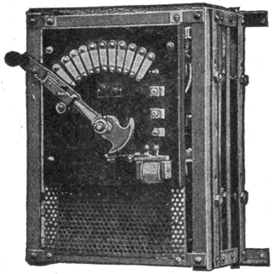
Fig. 760.--Cutler-Hammer speed regulator with no voltage release, regulation by armature resistance only, reducing speed of motor below normal. No resistance in the armature circuit. No provision is made in regulators of this type for increasing the speed of the motor. The maximum speed obtainable when these regulators are used is, therefore, the normal speed at which the motor is designed to operate with no resistance in circuit. With all resistance in circuit and the motor taking normal current these regulators will reduce the speed of the motor 50 per cent. If the motor be taking less than normal current the percentage of speed reduction obtainable will be correspondingly less. The notched fan tail extension on the lower end of the lever engages with a magnetically operated pawl to hold the lever squarely on any contact so long as the no voltage release magnet is energized.
Ques. How is a wide range of speed regulation secured?
Ans. By a combination of the two methods.
Regulation by Armature Resistance.--Speed regulators for this method of regulation, are designed to carry the normal current on any contact without overheating and when all the resistance is in the circuit, they will reduce the speed of the motor about 50 per cent. provided the motor be taking the normal current. When operating without resistance in the armature circuit, shunt wound and compound wound motors will regulate to approximately constant speed regardless of load. This [684] characteristic of inherent regulation is lost, however, when armature resistance is employed to reduce the speed of the motor, fluctuations in load resulting in fluctuations in speed, which become more noticeable as the amount of resistance inserted in the armature circuit is increased. Accordingly, it becomes necessary to move the lever of the speed regulator forward or backward to again obtain the speed at which the machine was operating before the load changed.
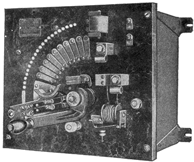
Fig. 761.--Cutler-Hammer compound starter with no voltage and overload release. This is a starting rheostat and field regulator combined. In operation, two levers are employed, both being mounted on the same hub post and one lying directly under the other. The upper lever only is provided with a handle, but when moving from the off position to the starting position (that is to say, from left to right) the lower, or starting, lever is carried along by the upper, or speed regulating, lever until it comes in contact with the no voltage release magnet where it is held fast by the attraction of the magnet, leaving the upper lever free to be moved backward over the field contacts, thus weakening the shunt field of the motor little by little until the desired speed is attained. During the operation of starting the motor, the field resistance is short circuited by an auxiliary contact (the slotted metal strip shown near center of rheostat) but as soon as the starting lever touches the no voltage release magnet or, in other words, when the motor has been accelerated to normal speed, this short circuit is removed, and the field resistance becomes effective for speed regulation. The motor is accelerated from rest to normal speed by moving both levers from left to right, while increases in speed above normal are obtained by moving the upper lever from right to left. Only the lower, or starting lever comes into contact with the no voltage release magnet. This lever is provided with a strong spiral spring which tends always to throw the lever back to the off position. Hence should the voltage fail, the no voltage release magnet releases the starting lever and this, in flying back to the off position, opens the armature circuit of the motor and carries the speed regulating lever with it to the off position. The upper, or speed regulating lever, not being influenced by the spring, though mounted on the same hub post as the starting lever, may be moved back and forth at will or left indefinitely in the position which gives the speed desired.
[685] When the speed of a motor driving a constant torque machine is reduced by inserting resistance in the armature circuit there is no corresponding reduction in current consumed. The motor runs more slowly simply because a part of the energy impelling it is shunted into the resistance and there dissipated in the form of heat. Hence, whether the motor be operating at full speed or half speed, the amount of current consumed is the same; the only difference being that in the one case all the energy taken from the line is expended in driving the motor while in the other case only one half is utilized for power, the other half being dissipated in the resistance. Speed regulation by armature resistance only is therefore open to two objections: 1, the difficulty of maintaining constant speed under varying load conditions, and 2, the necessity of wasting energy to secure speed reduction. These objections are, in part, offset by the fact that speed reduction by armature resistance may be applied to any motor of standard design and requires nothing more than the simplest and least expensive speed regulating rheostat.
In cases where the motor will be operated nearly always at full speed, the difference in first cost of the installation may justify the use of the armature resistance method of control. As a rule, speed regulation by shunt field resistance is preferable.
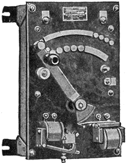
Fig. 762.--Cutler-Hammer compound speed regulator with no voltage and overload release; regulation by combined armature and shunt field resistance, designed to both decrease and increase the speed of a motor. Speed reduction is accomplished by inserting resistance in the armature circuit, the maximum amount of speed reduction obtainable with these controllers being 50 per cent. below normal. Speed increase is obtained by inserting resistance in the shunt field circuit, the maximum amount of speed increase obtainable with these controllers being 25 per cent. above normal.
Regulation by Shunt Field Resistance.--Since regulation by this method is for speeds above normal, a starter must be used to bring the motor up to its rated speed. Usually the starter is combined with the regulator, as shown in fig. 761, the device being called a compound starter.
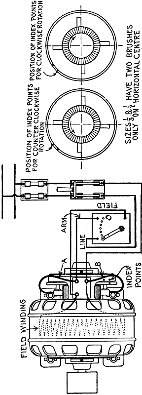
Figs. 763 to 765.--Holzer-Cabot shunt wound motor; diagrams showing connections and positions of index point for forward and reverse rotation.
LOCATION AND SETTING.--The motor should be placed in as cool, clean and well ventilated a location as possible, away from acid or other fumes which would attack the metal parts or insulation, and should be easily accessible for cleaning and oiling. Do not put it in some corner where care of motor will be neglected because of the trouble of getting at it. The motor should be set so that the shaft is level and parallel with the shaft it is to drive so that the belt will run in the middle of the pulleys. Do not use a belt which is much too heavy or too light for the work it has to do, as it will materially reduce the output of the motor. The belt should be about one-half inch narrower than the pulley.
ROTATION.--In order to reverse the direction of rotation, interchange leads A and B, and shift brush ring as shown in the diagram above.
SUSPENDED MOTORS.--Motors with ring oil bearings may be used on the wall or ceiling by taking off end caps and revolving 90 or 180 degrees until the oil wells come directly below the bearings.
STARTING.--Before starting the motor see that the armature revolves freely, that the bearings are full of oil, and the oil rings are in place and free to turn.
[687] Examine connections carefully to see that they are according to above diagram, after which proceed as follows:
1. Close the main knife switch. This action should not allow any current to pass through the motor (see Note 2);
2. Move the lever of the starting rheostat quickly and squarely onto the first segment, and hold it there for about a second;
3. Move the lever to the second segment and hold it there for about a second;
4. Move the lever to the third segment and hold it there for about a second, and so on from one segment to the next until the lever has been moved over all the segments to the short circuit position, where it should be held firmly by the retaining magnet.
If the motor do not start when the lever of the starting rheostat is on the third segment, open the main knife switch and look for the trouble. This may consist of any of the following:
a. Wrong connections;
b. Too great a load on the motor;
c. The motor brushes not in proper position;
d. An open circuit of some kind;
e. A short circuit of some kind.
NOTE 1.--It is always advisable, in case of trouble, to make sure that the fields of the motor are magnetized. This test is easily made by first closing the main knife switch, then moving the lever of the starting rheostat to the first segment, and finally having an assistant place a screw driver or other piece of iron against the pole pieces of the motor. If the fields be magnetized, a heavy pull on the iron should result.
NOTE 2.--Any possibility of arcing on the first contact of the starting rheostat when starting can be obviated by first moving the lever onto the initial contact, holding it there, and then closing the main line switch, after which proceed as per paragraphs 3 and 4.
TO STOP THE MOTOR.--Open the main knife switch and let the starting rheostat take care of itself. The lever will not fly back immediately, but will hold until the motor has slowed down considerably.
NOTE.--The above directions apply only to starters of the sliding contact type.
TEMPERATURES.--If located as instructed above, these motors will carry full load as indicated on the name plate on the motor with a temperature rise of not over 40 degrees Centigrade, or 75 degrees Fahrenheit above the surrounding air. This will feel hot to the hand but is far below the danger point. If the motor feel too hot, get a thermometer and measure the temperature. To do this, place the bulb of the thermometer for 10 minutes against the frame, cover with a cloth or piece of waste, and note temperature as compared with that of room. If the motor run in a small, enclosed space with no ventilation, the temperatures will be somewhat higher than those given above.
OILING.--Fill the oil wells to the overflow before starting and keep them full. Use good "dynamo oil." Be sure that the oil rings turn freely while the motor is running. If in a dirty place, draw off the old fluid and fill with new every two or three months.
CARE OF MOTOR.--The motor must be kept clean. If the commutator become rough, smooth it up with No. 00 sandpaper moistened with oil. When fitting new brushes or changing them, always sandpaper them down until they fit the commutator perfectly, by passing to and fro beneath the brush a strip of sandpaper, having the rough side toward the brush.
Brushes must always be renewed before the metal of the holder comes in contact with the commutator.
Don't use anything on commutator except good mineral machine oil, or kerosene, and this only in very small quantities applied with a cloth having no lint or threads.
Fig. 766.--Sectional view showing principal parts of Reliance adjustable speed motor: 1, lever fulcrum pin; 2, lever; 3, sliding thrust bearing box; 4, ball bearing; 5, armature shaft end nut; 6, cap; 7, commutator end yoke; 8, lever rod; 9, compression spring; 10, steel frame; 11, speed adjustment nut; 12, thrust collars and pins; 13, hand wheel rod; 14, hand wheel; 15, sleeve nut; 16, oil well cover; 17, bearing bushing; 18, sleeve; 19, oil ring; 20, pinion end yoke; 21, rocker arm; 22, brush holder stud; 23, brush; 24, commutator; 25, armature; 26, armature laminations; 27, armature coils; 28, armature end plate; 29, armature shaft; 30, leads; 31, axial position of commutating pole; 32, axial position of main field pole; 33, slide rail screws; 34, end yoke cap screws; 35, slide rails; 36, commutating coil; 37, commutating pole; 38, main field pole; 39, main field coil.
Fig. 767.--Cutler-Hammer reversible starter with no voltage release, adapted to start and operate motor at full speed in either direction, such for instance as motors driving auxiliary motions on lathes, planers and other machine tools which may rotate in either direction but always at constant speed. They are not designed to reduce the speed of the motor, but merely to start it and bring it smoothly up to full speed in either direction. Two no voltage release latching devices are provided so that the lever will be held in the full speed position in either direction so long as the voltage of the line remains constant. On failure of voltage a strong centering spring attached to the hub-post of the lever throws the latter to the central, or off position. The shunt field circuit is not opened by starters of this type.
The weakening of the shunt field of a motor by the insertion of resistance in the shunt field circuit causes the armature to revolve more rapidly. One advantage of this method of control is that the motor will inherently regulate to approximately constant speed under widely varying load conditions. Another advantage is found in the fact that all of the current taken from the line is utilized for power, the changes in speed being obtained not by dissipating a portion of the effective energy in the resistance (as in the case of the armature resistance method of [690] control) but by weakening the reverse voltage by inserting resistance in the shunt field circuit. Speed increase by shunt field weakening is limited, however, to about 10 to 15 per cent. above the normal speed in motors of standard construction. Greater ranges of speed can be obtained from motors especially designed for shunt field control but should not be attempted with motors of standard design without first ascertaining from the manufacturer the maximum safe speed.
Combined Armature and Shunt Field Control.--Regulation by combined armature and shunt field resistance is by far the easiest way of obtaining a wide range of speeds. Rheostats embodying these methods are known as compound speed regulators, one form being shown in fig. 762. Standard regulators can be obtained giving a wide range of speed variation, and special regulators may be constructed giving practically any desired range.
Selection of Starters and Regulators.--Unsatisfactory operation of these devices is, in nearly all cases, due to lack of precaution in selecting the proper piece of apparatus for the work to be done. One of the commonest errors is to select a rheostat of insufficient capacity. If the current required to operate the motor at full speed with no resistance in circuit be greater than the rated capacity of the rheostat, overheating of the resistance will result. An increase in temperature even to a point where the hand cannot be held on the enclosing case need cause no apprehension, but should the resistance become red hot it indicates that the apparatus is being worked far beyond its capacity, and the load on the motor should be reduced or a regulator of greater capacity substituted.
If the current required to operate the motor at full speed with no resistance in circuit be less than the rated capacity of the [691] rheostat no overheating will occur, but it will not be possible to secure the full 50 per cent. speed reduction the rheostat is designed to give with all resistance in circuit.
Fig. 768.--Various sizes of Watson commutator. The segments are punched from hard drawn copper strip and are insulated from each other and the core by amber mica, of hardness corresponding to that of the copper in order that the wear of mica and copper may be uniform. The segments are assembled in a ring under great pressure and are repeatedly heated and tightened, being finally secured and rigidly locked together.
In ordering a starter or regulator, the manufacturer should be furnished with the following information:
Fig. 769.--Organ blower speed regulator; diagram showing operation and method of installing. A cord running from the top of the organ bellows passes over two pulleys and is then made fast to the chain furnished with the regulator. This chain passes around a sheave which turns on a post projecting from the center of the slate panel. Attached to the lower end of the chain is a weight, also furnished with the regulator. As the air is exhausted from the bellows the latter slowly collapses, drawing the rope down with it, and in so doing turns the sheave from left to right, thus cutting resistance out of circuit and increasing the speed of the motor which pumps air into the bellows. Responding to the inrush of air, the bellows expands, relaxing the tension on the rope which is now pulled in the opposite direction by the weight, thus turning the sheave from right to left, cutting resistance into circuit once more and slowing down the motor. The speed of the motor is thus automatically regulated by the bellows, with the result that a practically uniform pressure is maintained at all times. In connection with an organ blower regulator it is necessary to install a separate starting rheostat. This is required for the reason that all organ bellows leak. During the intermissions in the musical part of the service, or at other times when the blower is not operating, the air gradually escapes and the bellows settles down, moving the rheostat arm to the right and cutting out resistance. With the motor at rest and the bellows empty all the blower regulator resistance would be short circuited and it is therefore necessary to avoid throwing the motor directly across the line when starting again. A starting rheostat with no voltage release is suitable for this purpose, and should be installed within easy reach of the organist, so that a moment or two before beginning to play he can move the lever of the starting box and get the motor into operation. Where remote control is desirable a self starter can be substituted for the manually operated starting box, in which case the entire installation can be controlled by a push button, or single throw knife switch.
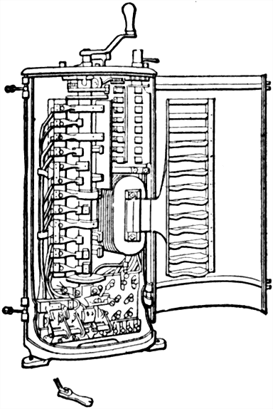
Fig. 770.--General Electric type K7 controller with cover open showing construction. The mechanism consists of a long spindle, carrying a number of heavy brass or gun metal segments, making contact for a longer or shorter time with a corresponding number of spring contacts. The spindle is provided at its upper end with a handle, and the various contacts are made by turning it through an arc of about 150°. For this method a moderate amount of resistance is employed. The first contact joins both motors and the full amount of resistance in series across the line, and as the motors are standing still, maximum current flows so that they exert their full torque. The moment they start to revolve, the current tends to fall, due to the generation of a reverse voltage; to prevent this and maintain a heavy current for some time, thus obtaining rapid acceleration, the resistance is arranged so that it can be gradually reduced, until at about the fourth notch the two motors are in series without resistance across the line. To increase still further the speed in the above type of controller, the series fields may be shunted, and then the next steps place the motors in parallel with the resistance.
Speed Regulation of Traction Motors.--The speed regulator for motors of this class is called a controller, and being located in an exposed place is enclosed in a metal casing. Controllers are designed to be used for starting, stopping, reversing, and regulating the speed of motors where one or more of these operations have to be frequently repeated.
[694] The controller used with a single motor equipment is practically the same as any other single motor starting box, excepting that the resistance has sufficient carrying capacity to be left in the circuit some time. When the motor is to operate at full speed all the resistance is cut out. To reverse, a reversing notch is placed in the armature or field circuit, but not in both.
Ques. What provision is made to overcome the arc when the circuit is opened?
Ans. A magnetic field is used with such polarity that it blows out the arc.
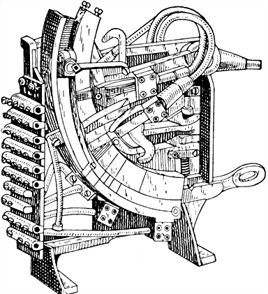
Fig. 771.--Controller of the Rauch and Lang electric vehicles. It is of the flat radial type. Two movable copper leaf contacts of ample size make all commutations necessary to obtain the various speeds. Five speeds forward and reverse are provided.
Magnetic blow out coils are used on all controllers designed for 500 volt circuits, and on types designed for lower voltages requiring more than 60 amperes normal capacity.
The coils are wound with either copper wire or flat strips of sufficient capacity to carry full load current continuously without undue heating, and after being wound they are treated with an insulating compound making them moisture proof.
[695] Ques. What provision is made to prevent reversal before bringing the controller lever to the "off" position?
Ans. Controllers having separate reversing cylinders are fitted with mechanical interlocks making it necessary to place lever in off position before reversing.
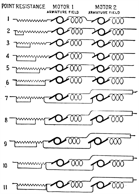
Figs. 772 to 782.--Diagram of controller connections, illustrating the series parallel method of two motor control.
Two Motor Regulation.--With a two motor equipment, the controller becomes more complicated because it must be arranged to switch the motors in series or in parallel, so as to secure economy at half and full speed. The various connections of series-parallel regulation are shown in figs. 772 to 782.
[696] From these diagrams it is seen that the motors are first operated in series until all the resistance is cut out by the controller (figs. 772 to 777).
The next point on the controller puts the two motors in parallel with some resistance in the circuit (fig. 778), which resistance is gradually short circuited on the remaining controller points, until at full speed all the resistance is cut out, the two motors remaining in parallel (figs. 778 to 782).
Stopping a Motor.--If it be desired to stop a motor, the main switch is opened. As the armature of the motor continues to operate, due to its inertia, it generates an electromotive force which sends a current through the shunt connected field circuit and helps to maintain the field excitation. When the speed of the motor has decreased sufficiently so as not to endanger the motor should the main switch be thrown, the current in the series magnet becomes weakened, and the spring throws back the starting box arm.
It should be noted that in stopping a motor having a starting box provided with a no voltage release simply open the main switch and do not touch the lever because otherwise, the self induced voltage of the field circuit may puncture the field winding or the insulation of the adjoining wires in the starting box.
They are not only the best, but the cheapest work published on Electricity. Each number being complete in itself. Separate numbers sent postpaid to any address on receipt of price. They are guaranteed in every way or your money will be returned. Complete catalog of series will be mailed free on request.
ELECTRICAL GUIDE, NO. 1
Containing the principles of Elementary Electricity, Magnetism, Induction, Experiments, Dynamos, Electric Machinery.
ELECTRICAL GUIDE, NO. 2
The construction of Dynamos, Motors, Armatures, Armature Windings, Installing of Dynamos.
ELECTRICAL GUIDE, NO. 3
Electrical Instruments, Testing, Practical Management of Dynamos and Motors.
ELECTRICAL GUIDE, NO. 4
Distribution Systems, Wiring, Wiring Diagrams, Sign Flashers, Storage Batteries.
ELECTRICAL GUIDE, NO. 5
Principles of Alternating Currents and Alternators.
ELECTRICAL GUIDE, NO. 6
Alternating Current Motors, Transformers, Converters, Rectifiers.
ELECTRICAL GUIDE, NO. 7
Alternating Current Systems, Circuit Breakers, Measuring Instruments.
ELECTRICAL GUIDE, NO. 8
Alternating Current Switch Boards, Wiring, Power Stations, Installation and Operation.
ELECTRICAL GUIDE, NO. 9
Telephone, Telegraph, Wireless, Bells, Lighting, Railways.
ELECTRICAL GUIDE, NO. 10
Modern Practical Applications of Electricity and Ready Reference Index of the 10 Numbers.