Title: Motor-car principles; the gasoline automobile
Author: Roger B. Whitman
Release date: March 3, 2023 [eBook #70194]
Language: English
Original publication: United States: D. Appleton and Compay, 1907
Other information and formats: www.gutenberg.org/ebooks/70194
Credits: Bob Taylor, Charlene Taylor and the Online Distributed Proofreading Team at https://www.pgdp.net (This file was produced from images generously made available by The Internet Archive)
MOTOR-CAR
PRINCIPLES
THE GASOLINE AUTOMOBILE
BY
ROGER B. WHITMAN
ILLUSTRATED
NEW AND ENLARGED EDITION
D. APPLETON AND COMPANY
NEW YORK, LONDON MCMX
Copyright, 1907, 1909, by
D. APPLETON AND COMPANY
[Pg v]
The development of the gasoline automobile at home and abroad has produced a great variety of designs, good, bad, and indifferent, but the advancement of the industry has weeded out the unsatisfactory and improved the good until with few exceptions the leading makes show a striking similarity in all but details. The advantages of certain forms of construction have been recognized, and their adoption by the large majority of makers has produced what may be called a standard type.
The object of this book is to explain the principles that underlie automobile construction and operation, and to illustrate the movements and mechanical combinations adopted in present-day practice. It is not the intention to explain the exact details of construction[Pg vi] of the different cars, and the illustrations have been prepared with the sole object of making the principles clear, for with an understanding of these there should be no difficulty in comprehending any particular application of them.
The lubrication table on pages 244 and 245, which was prepared by Mr. T. D. Hanauer, is reproduced through the courtesy of the Scientific American.
The advantages of magneto ignition for internal combustion engines are so obvious that designers and inventors have directed their attention to the perfection of apparatus that will improve present methods. The number of systems proposed for the purpose is very large in comparison with the number in actual and practical use, and as in a work of this size it would be impossible to describe the many methods for the application of the magneto that are on the market, attention has been given only to those that are in actual, everyday use. The absence of a practical treatise on the principles, application, and care[Pg vii] of low and high tension magnetos is the reason for the addition of the appendix to this work.
R. B. W.
[Pg ix]
| CHAPTER I | |
| GASOLINE-ENGINE PRINCIPLES | |
| PAGES | |
| Properties of gases—Steam-engine principles—Gasoline-engine principles—Combustion and explosion—Events of cycle—Four-cycle and two-cycle engines—Strokes of cycle—Fly wheel—Valves—Inlet stroke—Inlet valve closing—Compression-combustion stroke—Advantages of compression—Instant of ignition—Advancing and retarding ignition—Limit of compression—Power stroke—Heat losses—Opening of exhaust valve—Exhaust stroke—Clearance—Back pressure—Steam and Gasoline engines compared—Gasoline—engine power | 1-19 |
| CHAPTER II | |
| ENGINE PARTS | |
| Crank shaft—Crank-shaft bearings—Relative position of cranks—Connecting rod—Wrist pin—Piston and piston rings—Automatically and mechanically operated valves—Cams and cam shaft—Secondary shaft—Two-to-one gears—Valve-lifter rod—Valve locations—Muffler—Engine cooling—Cooling by Water—Pumps—Radiators—Pressure and gravity systems—Cooling by air—Lubrication | 20-36 |
| CHAPTER III | |
| ENGINE BALANCE | |
| Vibrations of engine—One-cylinder engine—Horizontal double-opposed—Two-cylinder vertical—Four-cylinder—Firing order—Balance of three- and six-cylinder engines—Comparison of engine types | 37-46 |
| CHAPTER IV | |
| TWO-CYCLE ENGINES | |
| Principle—Construction—Ports—Cycle—Action—Advantages and disadvantages | 47-51 |
| CHAPTER V | |
| CARBURETION AND GASOLINE FEEDS | |
| Carburetion—Carburetor—Carburetor parts—Carburetor action—Necessity for auxiliary air—Auxiliary air inlet—Automatic and mechanically controlled air inlet—Carburetors with side and central mixing chambers—Mechanically controlled carburetor—Surface carburetors—Gravity feed—Pressure feed—Check and relief valve | 52-73 |
| CHAPTER VI | |
| IGNITION | |
| Ignition system—Electric current—Parts of ignition system—Flow of current—Conductors and insulators—Resistance—Measurements of current—Lead and return wires—Grounding the return—Generators—Dry cell—Storage cell—Electrolyte—Hydrometer—Battery connections: series, parallel and multiple—Magnetism—Magnets—Magnetic lines of force—Magnetic field—Field and armature—Magneto and dynamo—Switch—Switch parts | 74-90 |
| CHAPTER VII | |
| IGNITION—(Continued) | |
| Ignition systems—Make-and-break system—Igniter—Tappet—Connections—Primary induction coil—Action of coil—Induced current—Magneto—Jump-spark system—Secondary induction coil—Primary and secondary circuits—Timers—Mechanical and magnetic vibrators—Spark plug—Circuit—Condenser—Secondary distributer | 91-111 |
| CHAPTER VIII | |
| TRANSMISSION | |
| Transmission parts—Clutches—Friction-cone clutch—Reversed friction-cone clutch—Multiple disk clutch—Internal expanding clutch—Change-speed mechanisms—Sliding gear: progressive and selective types—Use of clutch in changing gear | 112-131 |
| CHAPTER IX | |
| TRANSMISSION—(Continued) | |
| Planetary type of change-speed mechanism—Individual clutch—Friction type—Final drive—Turning the direction of the power—Bevel gears—Single-chain drive—Propeller-shaft drive—Universal joints—Live axle—Floating axle—Torsion rod—Double-chain drive—Jack shaft—Differential—Bevel-gear differential—Spur-gear differential—Driving-gear ratios | 132-160 |
| CHAPTER X | |
| RUNNING GEAR | |
| Steering—Front axle—Steering knuckles and arms—Drag link—Steering principles—Steering mechanisms—Brakes: contracting and expanding—Brakes: single- and double-acting—Running brake—Emergency brake—Engine as a brake—Brake equalizer—Tires—Tire construction—Tire inflation—Skidding—Antiskid devices—Springs—Shock absorbers—Distance rods | 161-178 |
| CHAPTER XI | |
| TROUBLES | |
| Ignition—Circuit—Battery—Magneto—Coil—Spark plug—Igniter—Timer—Secondary distributer—Switch—Gasoline—Tank—Carburetor—Compression—Cooling—Freezing—Lubrication | 179-202 |
| CHAPTER XII | |
| LOCATING TROUBLE | |
| Make-and-break ignition—Jump-spark ignition—Carburetor—Engine will not start—Engine will not deliver full power—Weak explosions—Missing explosions—Missing at high speed—Engine starts well, but comes to a stop—Overheating—Engine comes to a stop—Noises | 203-219 |
| CHAPTER XIII | |
| MAINTENANCE AND CONSTRUCTION | |
| Inspection—Washing the car—Tires—Care of the engine—Care of the chains—Valve grinding—Care of the steering mechanism—Care of the springs—Adjusting the vibrators—Matching coils—Adjusting the carburetor—Setting the valves—Ignition wiring | 220-242 |
Lubrication Table 244-245
| APPENDIX | |
| Magnetism—Induction—Magneto principles—General magneto troubles—Low tension ignition system—Setting up, care and troubles—Low tension magneto with secondary coil—Direct high tension magneto—Bosch two-spark magneto—Bosch four-spark magneto—Dual systems—Magnetic plug ignition—Inductor magnetos | 247-326 |
Testing Chart Between 326 and 327
Index 327-339
[Pg xv]
| FIG. | PAGE | |
| 1. | Engine Actions | 3 |
| 2. | Gasoline Engine Cycle | 7 |
| 3. | Gasoline Engine in Section | 21 |
| 4. | Crank Shafts | 22 |
| 5. | One-Throw Crank Shaft | 23 |
| 6. | Connecting Rod | 23 |
| 7. | Piston and Piston in Section | 24 |
| 8. | Piston Rings | 24 |
| 9. | Conical Valve Seat | 25 |
| 10. | Automatic Inlet Valve in Cage | 25 |
| 11. | Cam Action | 27 |
| 12. | Four Arrangements of Valves | 29 |
| 13. | Circulation of Cooling Water | 31 |
| 14. | Types of Pumps | 32 |
| 15. | Radiator Constructions | 33 |
| 16. | Radiator and Fan | 33 |
| 17. | Engine Arrangements Showing Order of Firing | 40 |
| 18. | Two-Cycle Engine | 48 |
| 19. | Carburetor Principles | 54 |
| 20. | Automatic Carburetors | 59 |
| 21. | Mechanically Controlled Carburetor | 63 |
| 22. | Float-Feed Carburetor with Gravity Gasoline Feed | 65 |
| 23. | Pressure-Feed Gasoline System | 67 |
| 23A. | Types of Float Valves | 69[Pg xvi] |
| 23B. | Types of Auxiliary Air Inlets | 71 |
| 24. | Battery Connections | 85 |
| 25. | Make-and-Break Ignition | 92 |
| 26. | Types of Timers | 99 |
| 27. | Mechanical Vibrator | 104 |
| 28. | Magnetic Vibrator | 104 |
| 29. | Spark Plug and Spark Plug in Section | 107 |
| 30. | Ignition Circuit | 108 |
| 31. | Friction Cone Clutches | 115 |
| 32. | Multiple-Disk Clutch | 117 |
| 33. | Sliding Gear—Progressive Type | 122 |
| 34. | Selective Type | 127 |
| 35. | Planetary Type | 133 |
| 36. | Individual Clutch and Friction Drive | 139 |
| 37. | Propeller and Single-Chain Drives | 143 |
| 38. | Typical Universal Joint | 144 |
| 38A. | Types of Shaft Drives | 145 |
| 39. | Live Axle—Non-floating Type | 147 |
| 40. | Live Axle—Floating Type | 147 |
| 40A. | Dead Axle with Driving Shaft | 149 |
| 41. | Torsion Rod | 150 |
| 42. | Double Side-Chain Drive | 151 |
| 43. | Differentials | 154 |
| 44. | Two Arrangements of the Drag Link | 162 |
| 45. | Steering Principles | 163 |
| 46. | Steering Mechanisms | 165 |
| 47. | Three Varieties of Brakes | 168 |
| 48. | Springs | 175 |
| 49. | Distance or Radius Rods | 177 |
| 50. | Jump-Spark Wiring Diagrams | 237[Pg xvii] |
| 51. | Jump-Spark Wiring Diagrams | 239 |
| 52. | Make-and-Break Wiring Diagram | 241 |
| 53. | Make-and-Break Wiring Diagram | 241 |
ILLUSTRATIONS IN APPENDIX
| 1. | Magnetic Lines of Force | 250 |
| 2. | Armature | 256 |
| 3. | The Armature and Lines of Force | 256 |
| 4. | The Armature and Lines of Force | 257 |
| 5. | The Armature and Lines of Force | 257 |
| 6. | The Armature and Lines of Force | 258 |
| 7. | The Armature and Lines of Force | 259 |
| 8. | Make-and-Break System | 271 |
| 9. | Eisemann Ignition System | 285 |
| 10. | Wiring Diagram, H.-T. Magneto Interchangeable with Secondary Coil | 298 |
| 11. | Wiring Diagram, Two-Spark Magneto | 302 |
| 12. | Timing Diagram, Two-Spark Magneto | 304 |
| 13. | Diagrams showing Position of Shield Revolving about Armature | 309 |
| 14. | Wiring Diagram, Four-Spark Magneto | 312 |
| 15. | Timing Diagram, Four-Spark Magneto | 314 |
| 16. | Bosch Jump-Spark Dual System | 318 |
| 17. | Remy Inductor | 321 |
| 18. | Inductor Giving Six Waves | 321 |
| 19. | Magnetic Igniter | 324 |
| 20. | Wiring Diagram of Magnetic Igniter System | 324 |
[Pg 1]
MOTOR-CAR PRINCIPLES
The action of a steam, gasoline, or hot-air engine depends on the principle that when air or other gas is heated it expands, and that if it is confined in a space that will not permit it to expand, in striving to do so it creates pressure against all parts of the chamber in which it is contained. The more a gas is heated, the more it will expand if it is free to do so, and if not free, the greater will be the pressure that it will exert in striving to expand. Pressure may thus be generated by heat, and following along similar lines, heat may be produced by pressure, for when the pressure of a gas is increased by compressing it, or forcing it to occupy a smaller space, the gas will become heated. The reverse is also true, that when a gas is cooled, its volume is[Pg 2] reduced, which reduces the pressure that it exerts; similarly, reducing the pressure by permitting the gas to expand reduces its temperature.
To state these principles in another form, to create pressure in a gas it must either be heated or compressed into a smaller space, and to reduce its pressure it must either be cooled or permitted to expand.
The action of a locomotive, the most familiar type of steam engine, is no mystery, and the production of steam in the boiler, its passage to the cylinder, and the application of its steady pressure against first one side of the piston and then the other, resulting in the turning of the driving wheels, are well understood. Water being converted into steam in the boiler, pressure is created because of the tendency of the steam to expand, but the only place in which it may expand is the cylinder, where in so doing it moves the piston.
[Pg 3]

Fig. 1.—Engine Actions.
A gasoline engine is similar to a steam engine in that its piston is moved by the pressure exerted by a heated and expanding gas; it is different in that the pressure is produced inside [Pg 4]of the cylinder by the combustion of an inflammable mixture of gasoline vapor, instead of being generated in a boiler away from the cylinder. The heat of the combustion creates great pressure, and as the piston is the only part that can give before it, it is moved from one end of the cylinder to the other, this motion being utilized in the turning of the crank shaft. The combustion, which is so rapid that the generally accepted term for it is explosion, can occur only after the mixture has been drawn into the cylinder, and so prepared that it ignites quickly and burns completely, with the object of obtaining the greatest possible heat from it in the shortest possible time. In order that one explosion may be followed by another, the burned and useless products of combustion must be expelled to make place for a fresh charge of the inflammable mixture.
These successive events, forming a cycle, must be performed as long as the engine runs, and the constantly changing pressure in the cylinder due to the movement of the piston allows a fresh charge to enter, prepares it, and expels the products of combustion after the[Pg 5] pressure that they have exerted has been utilized.
While in the great majority of steam engines the steam acts first on one side of the piston and then on the other, in an automobile gasoline engine the pressure is exerted on only one side, the combustion of the mixture taking place between the piston and the closed end, or head, of the cylinder. The other end of the cylinder is open, and the piston slides between the ends, its movement from one end to the other, called a stroke, corresponding to a half revolution of the crank shaft.
Gasoline engines are divided into two classes, according to the number of strokes of the piston that are necessary to accomplish the cycle; in the most usual type, four strokes are necessary, the class being called the four-stroke-cycle, or four-cycle, in distinction to the two-stroke-cycle, or two-cycle, in which but two strokes are necessary.
Of the five events that compose the cycle, three (the inlet, during which the fresh mixture enters the cylinder, its compression or preparation, and the exhaust of the burned gases) are performed[Pg 6] by the piston; during the power event the piston is moved by the pressure resulting from the combustion, while the combustion event is due to an outside source. In the four-cycle type of engine, which is in almost universal use for automobiles, the events are considered with reference to the movement made by the piston during which they are performed, and may be called the inlet, compression-combustion, power, and exhaust strokes. In order that the engine may continue to run, it is obvious that the events must be performed in the correct order, and that the failure of one will affect all the others.
During the inlet stroke, a charge of fresh mixture enters the cylinder as the piston makes an outward stroke from the closed toward the open end. When the piston makes the following inward stroke, the mixture is compressed and combustion occurs, the pressure from which drives the piston outward on the power stroke. This is followed by another inward stroke, which pushes the burned gases out of the cylinder. It will be seen that power is developed during only one stroke of the four, [Pg 8]the other three being required in the preparation for the following power stroke. The movement of the piston over these three dead strokes is secured by attaching to the crank shaft a heavy fly wheel, the momentum of which, acquired during the power stroke, keeps the crank shaft revolving and the piston in motion while the events are performed.
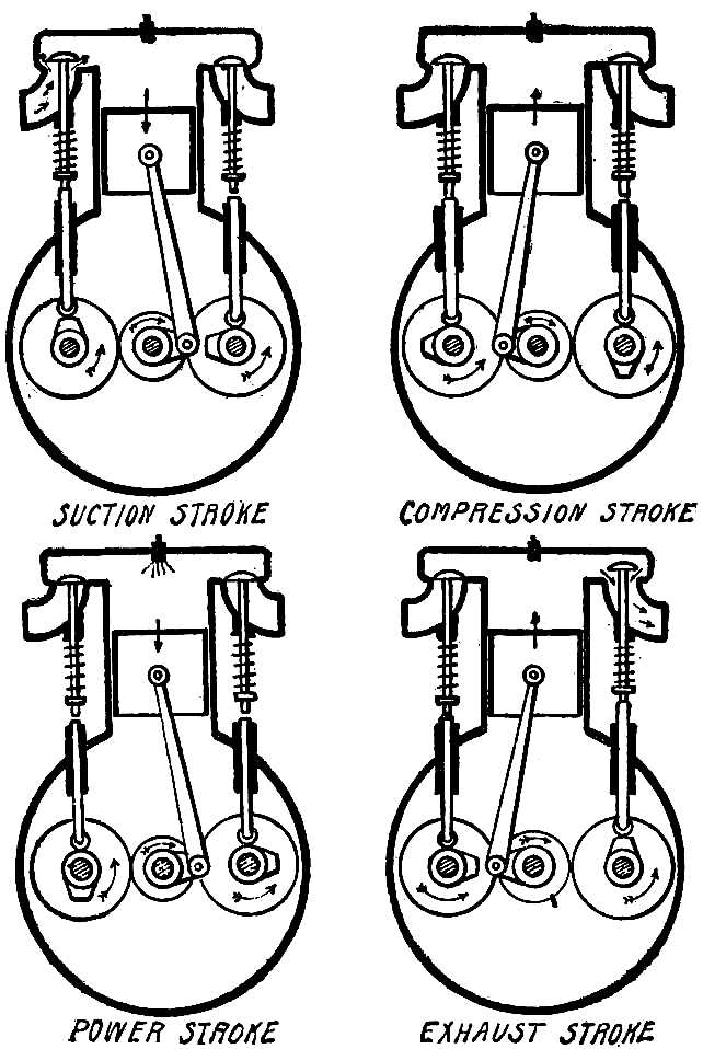
Fig. 2.—Gasoline Engine Cycle.
The space between the piston and cylinder head in which the combustion occurs is called the combustion space, and the inlet and exhaust valves open into it, the first being that by which the fresh mixture enters, and the second that by which the products of combustion escape. The device for igniting the mixture projects into the combustion space, and the means of ignition in universal use for automobile engines is an electric spark.
During the stroke (Fig. 2), the piston is moved outward by the crank shaft, which is revolved either by hand or by the momentum of the fly wheel. This movement increases the size of the combustion space, thereby reducing[Pg 9] the pressure in it, and the higher pressure of the atmosphere outside of the cylinder will force fresh mixture into the combustion space, the inlet valve being open to admit it. If the piston moves slowly, the mixture will be able to enter fast enough to keep the pressure in the combustion space equal to that outside, but at the high speed at which a gasoline engine is run the piston will reach the end of its stroke before a complete charge has had time to enter, so that the pressure in the combustion space will still be below that of the atmosphere. If the inlet valve closed at this point so that no more mixture could enter, the combustion of the partial charge would result in a lower pressure than would be possible with a full charge; the inlet valve should therefore remain open until the piston reaches the point of its next inward stroke at which the pressure in the cylinder equals that outside.
The compression and the combustion of the charge occur during the next inward stroke of the piston.
[Pg 10]
The period between the bringing together of the liquid gasoline and air and its admission to the cylinder is too brief to secure perfect combination, and the mixture that results is not satisfactory. A portion of the air will not have been able to come into contact with the gasoline, and much of the liquid will not have been vaporized; what passes into the cylinder consists of pure air, liquid gasoline, and a more or less perfect mixture of the two. The combustion of this would be slow and incomplete, resulting in loss of power and waste of fuel. In order to render the mixture more perfect, advantage is taken of the heat that is produced by compression; the inward stroke of the piston raises the temperature of the mixture by compressing it, the heat rendering the gasoline more volatile, and the compression forcing it into combination with the air. Even this does not result in the formation of a perfect mixture, for the period is too short to effect it. The failure of an engine to deliver full power may often be traced to this condition, for the air and gasoline vapor, instead of being thoroughly combined and mixed, will be in[Pg 11] layers, so to speak, and the combustion will be slow and uneven. Future development of the internal combustion engine will no doubt eradicate this, to the increase of efficiency and economy.
The charge of inflammable mixture can produce a certain amount of heat, and the more rapidly and completely this heat is obtained, the greater and more sudden will be the rise in pressure. The pressure will be greater when the mixture is contained in a small space than when in a large, and as the combustion space is smallest when the piston is at its inmost point, the greatest pressure will be obtained if combustion is complete at this point. If the combustion of the mixture were instantaneous, it should be ignited at this point; but even though very rapid, it nevertheless burns slowly enough to make it necessary to ignite it sufficiently before the end of the stroke to have the combustion complete as the piston comes into position to move outward. The instant at which the mixture must be ignited in order to produce this result depends on the speed of the piston, for the interval[Pg 12] between the ignition of a good mixture and its complete combustion does not vary to any great extent. When the piston is moving slowly, the mixture may be ignited toward the end of the compression stroke, for there will be sufficient time for complete combustion by the time the stroke is ended; but when moving at high speed, ignition must occur much earlier in the stroke, as otherwise the piston will have completed the compression stroke and begun to move outward on the power stroke before the mixture is entirely burned. The instant at which ignition occurs also depends on the mixture that is used, for its quality and proper combination make a difference in the rapidity with which it burns. The better the quality of the mixture, the faster and more completely it will burn, and ignition may occur later in the stroke than would be possible with a mixture of poor quality. As the mixture is ignited by the passing of an electric spark in the combustion space, the difference in the instant at which it occurs may be secured by permitting the spark to pass earlier or later, and this is under the control of the driver.
[Pg 13]
When ignition occurs early in the compression stroke, the spark is said to be advanced, in distinction to a retarded spark, which passes when the compression stroke is more nearly complete.
If the spark is advanced too much, combustion will be complete before the piston has reached the end of the compression stroke, and it will be necessary to force it to the end of the stroke against the pressure by the momentum of the fly wheel, in order that it may get into position to move outward on the power stroke. In such a case, the momentum may not be sufficient to overcome the pressure, and the piston will be brought to a stop. A retarded spark results in the combustion of the mixture being completed after the piston has begun to move outward on the power stroke, and the pressure will then be reduced because it is exerted in a larger space, the piston consequently being moved with less force; if the spark is still further retarded, the combustion will not be complete by the time the exhaust begins, and the heat from only a portion of the mixture will be utilized, because it will[Pg 14] still be burning as it is forced out of the cylinder.
The position at which the spark occurs is one of the means by which the speed of the engine is controlled, for the low pressure that results from a retarded spark moves the piston at low speed, while the greater pressure from an advanced spark drives the piston outward with more force and higher velocity.
While high compression of the charge improves its quality, and results in combustion being more rapid and complete, it has limits, and if carried too far the heat generated by the compression will be sufficient to ignite the mixture. This would have a bad effect on the operation of the engine, for the pressure would then be produced at the wrong point of the stroke, retarding instead of assisting the revolution of the crank shaft. Modern practice has shown that in engines that are maintained at a proper temperature the best results are obtained by compressing the mixture to from sixty to eighty pounds to the square inch; there are instances in which a higher compression is obtained, but the liability[Pg 15] to ignite the mixture prematurely makes it undesirable.
The increasing size of the combustion chamber as the piston moves outward on the power stroke permits the gases to expand, and in doing so the temperature will fall, the pressure decreasing in consequence. A further decrease in pressure is caused by the hot gases being in contact with the metal cylinder and piston, which absorb heat. The more slowly the engine runs, the longer the gases will be in contact with the cylinder walls, and the more opportunity there will be for loss of heat from this cause; at higher speeds, there will be less time for heat to be absorbed by the cylinder walls, and more will be utilized in expanding the gases and producing work.
Even at the outmost position of the piston, the combustion space will not be large enough to permit the gases to expand until their pressure has dropped to that of the atmosphere, so that they will still be exerting pressure. By opening the exhaust valve, the gases will have an outlet[Pg 16] for expansion, and will begin to rush out. While the pressure might be utilized against the piston to the end of the power stroke, it has been found that better results are obtained by opening the exhaust valve before the piston reaches the end of the power stroke. There is then a higher pressure forcing the gases out than there would be later in the stroke, and the greater quantity of gases that escapes leaves less to be expelled during the exhaust stroke.
The inward movement of the piston pushes out of the open exhaust valve the gases that have not escaped through their desire to expand. The exhaust valve remains open for the entire stroke, but when the engine is running at high speed the piston moves so rapidly that the gases cannot escape fast enough to prevent their being slightly compressed. When the piston is at its inmost point, the gases are still flowing through the valve because of this slight compression, and if the valve closed, a portion would be retained. The best results come from the closing of the exhaust valve not[Pg 17] at the end of the exhaust stroke, but a short time after the piston has begun to move outward again, during which period the compression forces the gases out. The exhaust valve closes at the point when the slight compression has been reduced to the pressure of the atmosphere by the escape of the gases and the enlargement of the combustion space.
If the piston completely filled the combustion space when at its inmost point, all of the burned gases would be expelled, but the necessity for leaving a space in which combustion may take place renders this impossible, and a small portion of the burned gases therefore remains in the cylinder. The space between the cylinder head and the piston when at its inmost point, called the clearance, should be as small as possible, in order that the amount of these gases remaining in the cylinder may not be sufficient to contaminate the fresh charge and weaken the pressure of its combustion.
The passages through which the burned gases are led away from the cylinder must be large and free from obstructions, for if a free[Pg 18] flow is not permitted back pressure will be set up, which will prevent the largest possible amount of gases from escaping, and leave a greater portion to contaminate the fresh charge.
The power that a gasoline engine is capable of developing depends on the size of the cylinder, the pressure acting on the piston, and the speed at which it operates. A steam engine, which obtains its pressure from a boiler, can do work as soon as the steam is turned into the cylinder, but a gasoline engine must be running before it can be called on to deliver power. Because of the cycle of events on which its operation depends, the piston must be forced to perform the inlet and compression strokes before pressure can be developed, and it is necessary to revolve the crank shaft by outside means until a charge of mixture has been taken into the cylinder, compressed, and ignited, when the engine begins to work by the pressure from the combustion, and takes up its cycle. Not until this has been done can it be called on to do work.
A steam engine can be made to deliver more power than it is built for by increasing the[Pg 19] pressure acting against its piston, and the full pressure of the boiler can be utilized when extra work is necessary. The power developed by a gasoline engine being greatly dependent on its speed, and there being no reserve by which greater power can be developed in emergencies, it is necessary for an engine of this type to be perfectly adapted to the work that is desired of it. At excessive speeds the piston acquires great momentum, which must be overcome at each end of a stroke by the crank shaft, and while a speed above normal may be attained, it results in the quick destruction of the bearings and the severe straining of the engine. The best results in efficiency and long life accompany the running of the engine at the slowest speed possible for the development of the required power.
[Pg 20]
The sudden and powerful outward movements of the piston under the pressure from the combustion are transmitted to a crank shaft, which must be of great strength in order to resist the heavy strains under which it operates. It is made of the best steel available for the purpose, and has as many cranks as the engine has cylinders. The cranks are generally made in one piece with the shaft for the sake of strength, and for stiffness there are as many bearings as possible. The number of bearings for the crank shaft of an engine with four or more cylinders depends on the arrangement of the cylinders. If the cylinders are evenly spaced, there will be room for a bearing between each pair of cranks, so that a four-cylinder engine will have five bearings, [Pg 22]one at each end, the other three being between the cranks. If the cylinders are in pairs, there will not be room between the cranks of a pair for a bearing, the only space for it being between the pairs; a four-cylinder engine built in this way will thus have but three bearings, one at each end and one in the center. Crank shafts are described by their bearings as three, five, etc., point crank shafts.
[Pg 21]
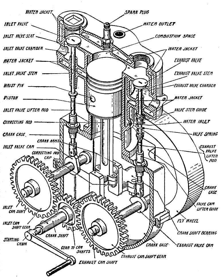
Fig. 3.—Gasoline Engine in Section.
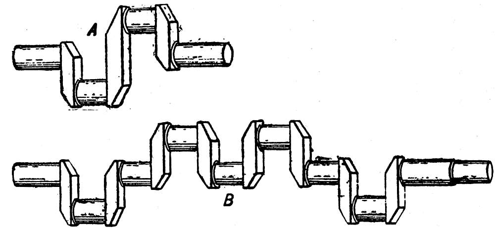
Fig. 4.—A, Two-throw crank shaft; B, four-throw crank shaft, 180°.
The relative positions of the cranks of a crank shaft are expressed in degrees of a circle; if, for instance, the cranks project from opposite sides of the shaft so that they are a half revolution apart, it is called a 180-degree crank shaft.
The outer ends of the crank arms, which correspond to the cranks of a bicycle, support[Pg 23] the crank pin, which may be likened to the pedal, and to this the large end of the connecting rod is attached, the small end being connected to the piston. The connecting rod must be of great strength, tough but not brittle, and is made of steel or bronze.
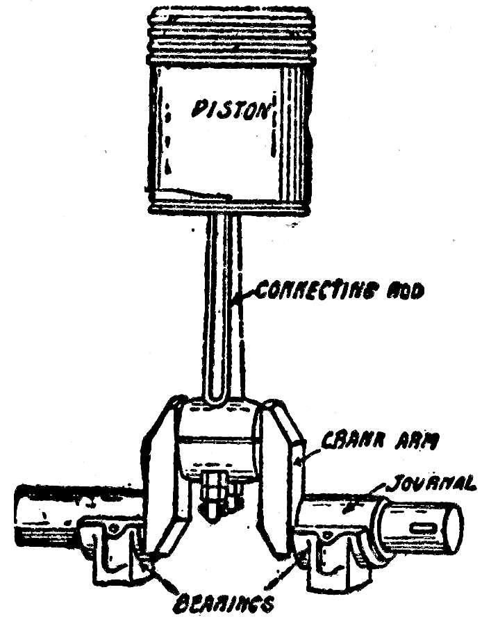
Fig. 5.—One-Throw Crank Shaft.
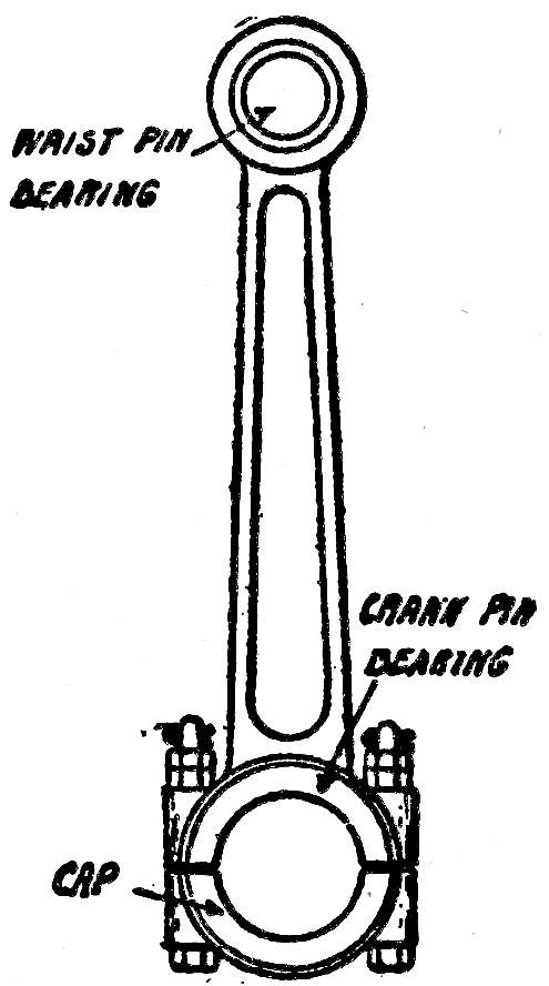
Fig. 6.—Connecting Rod.
The piston is a trifle smaller than the bore of the cylinder, and its length is usually greater than its diameter. It is hollow, with one end closed, the closed end being that against which the pressure is exerted. A wrist pin passes through it, and through the small end of the connecting rod, to enable the latter to swing from side to[Pg 24] side in following the turning of the crank shaft. A tight joint is maintained between it and the cylinder walls by cast-iron piston rings, which are of square or rectangular cross-section, split so that they may spring open, and fitted into grooves cut around the piston. They are of such shape that their tendency to expand keeps them pressed against the cylinder walls, but being split, their elasticity prevents their binding; they fit the grooves snugly, and while they may move freely in them, they hold the pressure from escaping. The number of rings varies with the design of the engine, but the most usual arrangement is three to a piston, placed around the upper end.
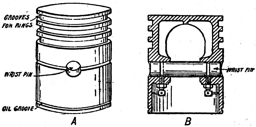
Fig. 7.—A, Piston; B, piston in section.
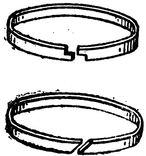
Fig. 8.—Piston Rings.
[Pg 25]
The cylinder should be of the highest grade of cast iron, with the smoothest possible surface for the piston to slide against.
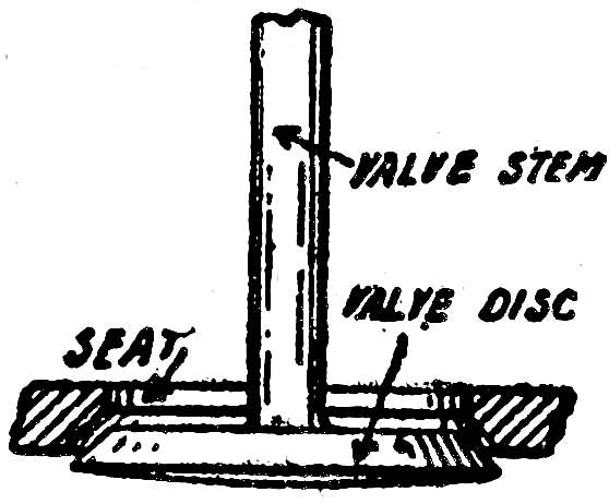
Fig. 9.—Conical Valve Seat.
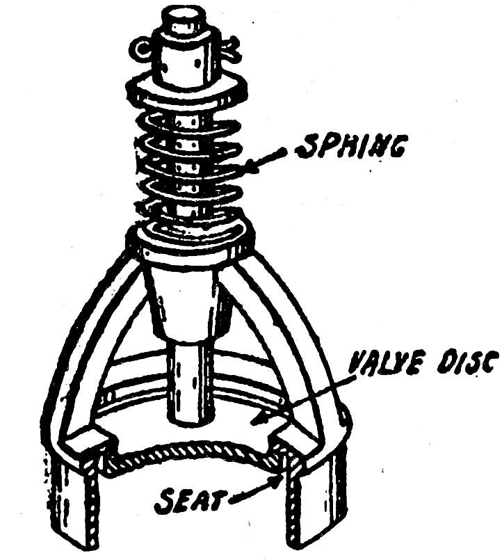
Fig. 10.—Automatic Inlet Valve in Cage.
The valve openings, or seats, are circular, and are usually made slightly funnel shaped, the disks that cover them being slightly conical to fit. The large end of the funnel is toward the combustion space, so that when the disk is lifted from its seat it moves inward. Valves are held against their seats by coil springs that surround the valve stems, which are rods extending from the center of the disks, and there are two methods by which they are opened. In an automatic valve, the spring that holds the disk against its seat is weak, and the higher pressure outside of the cylinder during the suction stroke forces the disk away from its[Pg 26] seat against the pressure of the spring. The valve remains open until the pressure in the combustion space is about equal to that outside, when the spring draws the disk back to its seat, to which it is held as long as the pressure inside is higher than that of the atmosphere. This arrangement is only possible for inlet valves, and is largely used, but exhaust valves, and often inlet valves as well, are mechanically operated; that is, they are opened and held open by a mechanism driven by the crank shaft, in the form of a cam. A cam can best be described as a “wheel with a hump on it,” or, in other words, it is a piece of metal mounted on a shaft, cylindrical in form except for one portion, which projects farther from the shaft than the rest. The cam revolves with the shaft, and the projection, called the nose, will displace anything resting against it. The illustration shows a cam in three positions of its revolution, with the end of a valve stem resting against it—the roller being attached to the stem to reduce the friction. The valve stem is held in guides, so that the only movement it may have is up and down; when the[Pg 27] cam revolves, the nose lifts the stem and opens the valve, holds it open as long as the flat end of the cam is under the stem, and when the nose passes from under, the valve is drawn to its seat by the spring.
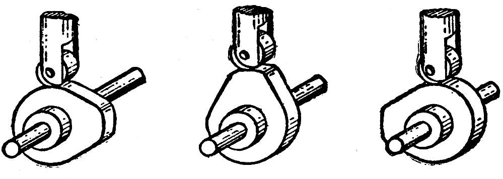
Fig. 11.—Cam Action.
The moment at which an automatic valve opens is governed partly by the tension of its spring; if it is too strong, greater pressure will be required to open it, and it will close sooner than if the tension is light. Accurate adjustment of this spring is necessary in order that the charge may enter the combustion space without delay, and continue to enter as long as possible. The opening and closing of mechanically operated valves depend on the shape of the cam, and not being affected by the more or less uncertain action of a spring, they are more positive in action.
[Pg 28]
The cam shaft on which the cam is mounted is driven by the crank shaft, but as the valve opens but once during two revolutions, the cam shaft revolves at half speed, making one revolution while the crank shaft makes two. This is done by means of gears.
If two gears running together, or in mesh, have the same number of teeth, they will make the same number of revolutions, but if one has twice as many teeth as the other, the smaller will revolve twice while the larger revolves once. As the cam shaft must revolve but once while the crank shaft revolves twice, its gear must have twice the number of teeth as the gear on the crank shaft. The cam shaft is also called the secondary, or half-time shaft, and the gears that drive it the two-to-one gears.
In some designs of engines, the nose of the cam bears directly against the valve stem, but it is more usual to place a valve-lifter rod, or push rod, between them, the cam acting on the rod and lifting it, and that in turn lifting the valve stem. When the nose of the cam is not acting on the stem or rod, there must be a small space between them, for if the stem or rod[Pg 29] rests firmly against the cam at all times, the valve disk might be prevented from seating firmly. The space is left between the stem and lifter rod, the spring acting only on the stem.
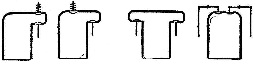
Fig. 12.—Four Arrangements of Valves.
The valves may open into the cylinder in a variety of ways; both may be in one pocket, or one may be in a pocket and the other in the head, or each in a separate pocket, or both in the head. The first two illustrations show automatic inlet valves, and the third and fourth mechanically operated valves; when two mechanically operated valves are in the head, it is necessary to open them by means of rocker arms, for because of their position it would be impossible for the valve-lifter rod to act directly on their stems.
If after the explosion the burned gases were permitted to escape directly into the open air from the cylinder, the effect would be the same[Pg 30] as the firing of a gun, and for the same reasons. The pressure in the cylinder being higher than that of the atmosphere, the sudden expansion of the gases would produce a report, and as this would be most undesirable for an automobile, provision is made by which the gases are cooled and permitted to expand gradually, so that when they reach the open air they are at its pressure, or nearly so. This is done in the muffler, or silencer, to which the exhaust pipe conducts the products of combustion. The muffler consists of a series of chambers of different sizes, one inside of the other; the gases pass from the smaller to the larger, expanding as they go, until from the largest they should escape without noise, having lost their heat and pressure.
While the pressure exerted during the power stroke depends on the heat of the gases, and it is necessary to have the engine hot in order that there may be as little loss of heat as possible, the temperature must not be permitted to rise to the point at which the lubricating oil would burn. Lubricating oil for gasoline engines is made to stand high heat, but if heated[Pg 31] beyond its limit it will burn, and then, besides the loss of its property of lubrication, a deposit of carbon, hard or gummy, will form, fouling the combustion space or piston rings, and interfering with the operation of the engine. Overheating is prevented either by circulating water through channels surrounding the combustion space, or by directing a blast of air against it.
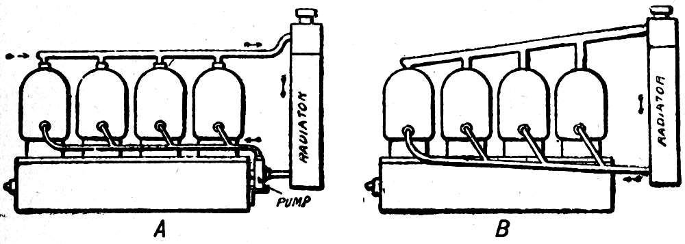
Fig. 13.—A, Force circulation water-cooling system; B, thermosiphon circulation water-cooling system. (Flow of water indicated by arrows.)
The channels, called water jackets, provided for the circulation of the water, are usually cast with the cylinder, or formed of sheet metal. Cool water enters at the bottom and escapes at the top, absorbing heat during its passage. Of the two systems of keeping the water in circulation, the most usual consists of a rotary[Pg 32] pump, which forces the water through the jackets and then to a cooler, or radiator, which is so placed that it is exposed to the air currents set up as the car moves. In order to cool the water, the radiator must have a large surface exposed to the air, and the water must pass through it in small streams. The early types consisted of coils of small copper tubing, on which were strung disks of copper, the water[Pg 33] flowing through the tubing, and the disks absorbing its heat and giving it up to the air, but these are being abandoned in favor of cellular or honeycomb radiators. These types, which are usually placed at the extreme front of the car, are made up of a great number of short lengths of small tubing, in any one of several shapes, placed side by side, and held together either by plates or by soldering their ends.
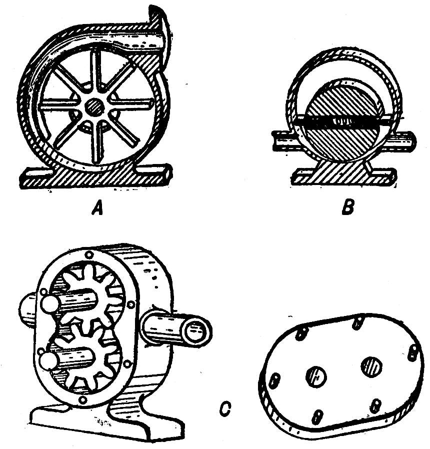
Fig. 14.—A, Centrifugal pump; B, vane pump; C, gear pump and cover.
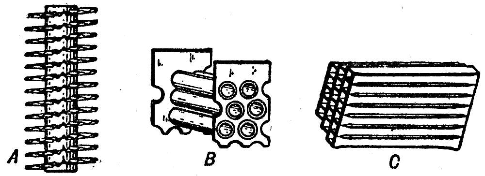
Fig. 15.—Radiator Constructions. A, Spiral flange (water passes through the tube); B, cellular, and C, honeycomb (air passes through the tubes; water passes between the tubes).
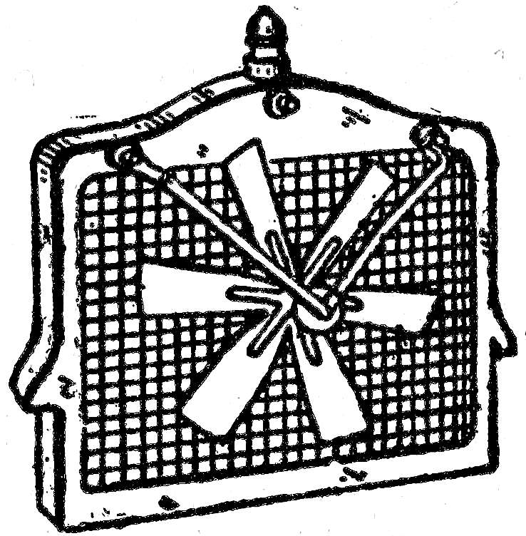
Fig. 16.—Radiator and Fan.
The heated water enters at the top of the case in which the tubes are contained, and flows to the bottom, finding passages between the tubes,[Pg 34] while the air passes through, being assisted by a fan driven by the engine.
The second system of keeping the water in circulation follows the principle that heated water tends to rise, its place being taken by the cooler water that tends to sink. This, called the thermosiphon or gravity system, requires all of the parts and connections to be large and completely filled with water. The water in the jacket rises as it absorbs heat from the cylinder walls, and flows out to the radiator, which it enters at the top. Its place in the jacket is taken by the cooled water from the bottom of the radiator, and this circulation continues, being more rapid as the difference in temperature between the heated and cooled water increases. It is naturally not so rapid as circulation that is forced by a pump, and more liable to become inoperative by the clogging of the pipes, jacket, or radiator.
Of the methods of increasing the surface of a cylinder in order to cool it by a blast of air, the most usual is to cast it with flanges that project from all parts of the combustion space. These become heated as the temperature of the[Pg 35] cylinder walls increases, and the air that is blown against them carries off the heat. Other methods consist of setting pins or copper strips into the cylinder walls, of such form that the air current strikes a surface composed of points, by which the heat easily passes to the air. Another system consists of surrounding the combustion chamber with a jacket open at the bottom, air being blown into it from the top by a powerful blower.
Other things that are necessary for successful air cooling are large valves by which the hot gases may be quickly discharged when their period of usefulness is ended, and small cylinders rather than large, as the heat from small quantities of gases may be carried off more quickly than from large.
The lubrication of a gasoline engine must be carefully looked after, as on its thoroughness depends the continued delivery of power. The most usual method of lubricating the piston and cylinder walls is to keep the crank case filled with oil to such a point that the end of the connecting rod dips into it in turning. This spatters the oil to all parts of the crank[Pg 36] case, and a portion is caught in a groove cut around the lower end of the piston. The inward movement of the piston spreads the oil on the cylinder walls, and it is distributed around the piston rings, so that they move easily in their grooves. As the oil is used up, it is replaced from a lubricator so that a constant level is maintained, and this operates either by gravity, or by a small force pump driven by the engine, or by the maintaining of pressure in the oil tank.
Mechanically operated or pressure lubricators supply oil to all parts of the engine, and as the quantity passed to each bearing is adjustable, a feed may be maintained that is exactly suited to the requirements.
The bearings of an automobile operate under such widely different conditions that one kind of lubricant will not be suitable for all. The maker of the car has tested the different oils, and it is advisable to follow his instructions on the brand and grade most suitable for each bearing, rather than to try experiments. The Lubrication Table on pages 244 and 245 gives the kind and quantity of lubricant most suitable to the work performed by each bearing.
[Pg 37]
A drawback to the use of reciprocating engines is that the weight of the piston and connecting rod in sliding first one way and then the other produces great vibration, and that the crank shaft in bringing these parts to a stop at each end of the stroke is subjected to violent shocks that in time wear it loose in its bearings. With internal-combustion engines this vibration, and the shock on the crank shaft, are greatly increased by the intensity with which the pressure is exerted.
Engines with one cylinder may be balanced to some extent by the use of counterweights attached to the crank shaft, and by the use of so heavy a fly wheel that its momentum produces a comparatively steady movement; but a perfect absorption of the vibration would[Pg 38] require the engine to be run at a constant speed, which is not possible with those used on automobiles.
In two-cylinder engines the vibration may be reduced by so arranging the parts that the pistons slide in opposite directions, the weight of one being balanced by that of the other. This plan is used in engines of the horizontal double-opposed type, which is considered to be the most satisfactory for low powers. The cylinders are horizontal, with their open ends toward each other, the crank shaft lying between them. The crank shaft is two-throw, 180°; that is, there are two pairs of crank arms, projecting from opposite sides of the shaft, so that they are a half revolution apart.
Two cylinder engines are also built with vertical cylinders, and are of two types, according to the construction of the crank shaft. In one, the crank shaft is 180°, and in the other both pairs of crank arms project from the same side of the shaft so that the crank pins are in line, this being called a 360° crank shaft.
In the 180° type one piston moves up as the other moves down, so that they balance,[Pg 39] but it results in the power strokes occurring in both cylinders during one revolution of the crank shaft, with no power during the revolution that follows.
To understand the reason for this, the order in which the events of the cycle occur must be recalled, and it must be remembered that of the four strokes of the piston during which they are performed the two outward strokes are inlet and power, and the two inward strokes compression and exhaust. If the piston of a two-cylinder vertical engine (Fig. 17) is moving downward on the power stroke, piston No. 2 will be ascending, and the only events that can then be performed in its cylinder are compression or exhaust. If performing compression, it will move under power during the next stroke (the other half of the revolution), No. 1 then exhausting (Table No. 1). This brings the two power strokes in one revolution, and during the next revolution there will be no power stroke, for No. 1 will be performing suction and compression, and No. 2 exhaust and suction.
[Pg 40]
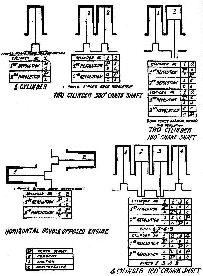
Fig. 17.—Engine Arrangements Showing Order of Firing.
If, as shown in the second table, No. 2 is [Pg 41]moving upward on exhaust while No. 1 moves down under power, its previous stroke, the first half of the revolution, will have been the power stroke, and the same condition will exist of two power strokes occurring in the same revolution.
In either case the balance of the moving parts is offset by the irregular production of power, which produces bad results in the setting up of strains in the engine, and the uneven running of the car.
In two-cylinder vertical engines with 360° crank shaft (Fig. 17) the pistons move up and down together, which of course results in bad balance. In this arrangement, however, the applications of power may be evenly spaced, for as the piston in cylinder No. 1 moves downward on the power stroke, piston No. 2 moves in the same direction, and may make either the inlet or power stroke. If it makes the inlet stroke, it must move inward before it can again move outward on the power stroke, and there will be an interval of one stroke between the power strokes of the two cylinders. To have the power strokes in the two cylinders occur[Pg 42] together, as suggested as the alternative, would obviously give bad results in the great strain imposed on the crank shaft, the weight of the fly wheel that would be necessary to carry two pistons through three dead strokes, and the jerky running of the car.
The defects of two-cylinder vertical engines with either design of crank shaft outweigh any possible advantage of that construction, and the horizontal double-opposed type, in evenly occurring power strokes, mechanical balance, and simplicity, is in almost universal use for cars of low power.
A two-cylinder engine does not require so heavy a fly wheel as a one-cylinder engine in proportion to the power delivered, because there is a power stroke every revolution instead of in alternate revolutions, and the parts must be carried over only one dead stroke instead of three. Similarly, the fly wheel of a four-cylinder engine may be still lighter, for in that type there are two power strokes in every revolution, with no dead strokes. At the same time, it is not possible to dispense with it entirely, for the pressure acting on the piston[Pg 43] at the beginning of the power stroke falls rapidly as the piston moves before it, and the momentum by which the fly wheel tends to revolve at a constant speed steadies and smooths what would otherwise be a jerky motion.
The crank shaft of a four-cylinder engine is 180°, four-throw, with the two end cranks projecting in the opposite direction to that of the two inside cranks. This arrangement is used in preference to having the cranks project alternately; that is, the first and third to one side and the second and fourth to the other, because of economy in manufacturing, and because practice has shown that it results in less vibration in the running of the engine.
This construction of the crank shaft does not permit the power strokes to occur in rotation, cylinder No. 2 following No 1, and then Nos. 3 and 4, for it has been explained that when cranks are 180° apart the power strokes occur during one revolution, and that when 360° apart there is a dead stroke between the two power strokes. Cranks 1 and 2 are 180° apart, as are 3 and 4, and also 2 and 4, but 2 and 3 are 360°; that is, their crank pins are in line,[Pg 44] which is also the case with 1 and 4. The power stroke in cylinder No. 2 may follow that in cylinder No. 1, but must be followed by that in cylinder No. 4, as that is 180° away from No. 2, and No. 3 comes last, being 180° from No. 4. The succession in which the power strokes occur, called the firing order, is thus 1, 2, 4, 3, and this is arranged for by the setting of the valves and the timing of the ignition.
This firing order was used for the first four-cylinder automobile engines, but it has lately been suggested that the firing order 1, 3, 4, 2 shows advantages in the reduction of strains and vibration, and is being adopted.
Three-cylinder engines are built with 120° crank shafts; that is, the cranks are one third of a revolution apart, instead of one half of a revolution, as is the case with 180° crank shafts. This gives three power strokes during two revolutions, and results in excellent balance. Six-cylinder engines have crank shafts of similar construction, and produce six power strokes during two revolutions, with the best balance that it is possible to obtain without an excessive number of cylinders. A power[Pg 45] stroke occurs at every 120° that the crank shaft revolves, and as each power stroke endures for a half revolution, or 180°, it follows that one commences when the previous one is only two thirds complete. This gives a very steady application of power, for the crank shaft is at all times operated by the driving effect of the combustion strokes, and it is possible to run the engine smoothly at greatly varying speeds by control of the position at which the spark occurs in the combustion space, and the admission of a greater or less volume of the mixture during the inlet stroke.
The type of engine that will give satisfaction depends on the work that is demanded of it, the care that it will receive, and the knowledge of the operator. A one-cylinder engine, having a minimum of parts, may be successfully managed by a novice, but its vibration, and the fact that it delivers power for only one fourth of the time that it runs, make it unsatisfactory for any but light work. Cars of medium power are almost universally equipped with horizontal double-opposed engines, with excellent results, and they are not difficult to[Pg 46] maintain. More powerful cars have four-cylinder vertical engines, which give a sufficiently constant pull for all practical purposes, with a correspondingly greater demand for care and attention. Six-cylinder engines are of doubtful advantage for general use, without the services of a chauffeur, for while they develop more constant power than engines with fewer cylinders, the complication of parts and the care necessary are increased.
[Pg 47]
The two-cycle type of gasoline engine differs from the four-cycle type described in the foregoing chapters in that the five events composing the cycle are performed during one revolution of the crank shaft, or two strokes of the piston, power being developed during every outward stroke of the piston instead of alternate outward strokes.
[Pg 48]
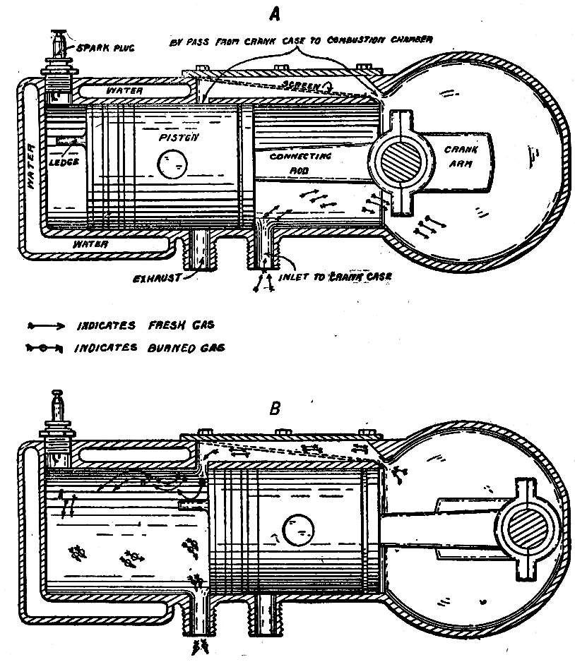
Fig. 18.—Two-Cycle Engine.
In order that this result may be attained, the construction of the engine is changed, and, as will be seen in Fig. 18, the crank case is utilized as a receiver for the mixture before it passes to the combustion space. The valves are replaced by ports, which are openings into the combustion space that are covered and uncovered by the piston as it slides in the cylinder. The inlet port is uncovered when [Pg 49]the piston is at the inmost point of its stroke (Fig. 18, A), and then admits the mixture to the crank case; the by-pass port and the exhaust port are uncovered when the piston is at the outmost point of its stroke (Fig. 18, B), the former then permitting the mixture to pass from the crank case to the combustion space, and the latter is that through which the burned gases escape after combustion has taken place.
During an inward stroke, the pressure in the crank case is reduced as the piston slides away from it, and fresh mixture is forced into it by the higher atmospheric pressure as soon as the inlet port is uncovered. This port is covered when the piston makes an outward stroke, and the mixture, not being able to escape, is compressed. Its tendency to expand causes it to flow to the combustion space when the by-pass port is uncovered, and in entering it strikes a ledge on the piston so that it is deflected to the top of the combustion space instead of being able to shoot across the cylinder and out the open exhaust port. The inward stroke of the piston covers these two ports and compresses the mixture, ignition occurring in[Pg 50] the regular manner. The pressure developed by the combustion drives the piston outward, and as soon as the exhaust port is uncovered (which is slightly before the uncovering of the by-pass port), the gases, which are still expanding, begin to escape, and are further expelled by the fresh charge that enters and drives them before it. Thus the five events of the cycle are performed during an inward and an outward stroke of the piston, the crank case end of the piston drawing a charge of fresh mixture into the crank case and forcing it into the combustion space, and the combustion chamber end compressing it and being acted on by the pressure from the combustion.
At slow speeds, two-cycle engines have advantages over the four-cycle type in the production of a power stroke at every revolution of the crank shaft, and the absence of valves and valve mechanism with their weight and possibility of giving trouble. This simplicity makes the two-cycle engine popular for motor boats, where they are run at slow and constant speed, but for higher and changing speeds these advantages are outweighed by disadvantages[Pg 51] that show little sign of being overcome.
With the engine running at a thousand revolutions a minute, it can be understood that the ports will be open for only a brief period during each stroke, and that the faster the engine runs the shorter will be the period during which the gases may enter or leave the combustion space. The inefficiency of two-cycle engines as compared with engines of the four-cycle type is due entirely to the fact that the burned gases have not sufficient time in which to escape from the combustion space, nor the fresh charge time to enter. The fresh charge that does enter being incomplete, and being contaminated by the portion of the burned gases that has not been able to escape, result in the “choking up” of the engine, and in the production of lower power than the dimensions and weight of the engine should warrant.
[Pg 52]
Pure gasoline vapor will not burn, and in order to render it inflammable it must be combined with oxygen. The simplest manner of effecting this is to mix air with it, and when the correct proportions are obtained, the oxygen supplied by the air will be sufficient to result in the complete combustion of the gasoline vapor, without a surplus of either of the ingredients. This mixing is called carburetion, the air being said to be carbureted. A correct proportion of gasoline vapor and air results in rapid combustion; an excess of air makes combustion slower, and excess of gasoline vapor prevents the combustion from being complete, a residue of carbon remaining. The correct proportions of air and gasoline vapor are obtained by the use of[Pg 53] a device called a carburetor, which is connected to the combustion chamber by the inlet pipe, and in such a manner that everything entering the combustion space by the inlet valve must first pass through it.
Liquid gasoline is led to the carburetor from the supply tank, and the air enters it when the pressure in the combustion space is reduced by the piston in making the inlet stroke. The speed with which the air flows through the carburetor depends on the extent to which the pressure is reduced, and the gasoline vapor that is required to form a mixture of the correct proportion must be maintained in accordance with it. While there are various classes of carburetors, practically all that are used for automobile engines are of the float-feed type; that is, the supply of gasoline is maintained by a float, just as water tanks are kept filled to a desired depth by a hollow metal ball that floats on the liquid and controls the valve by which the water enters.
[Pg 54]
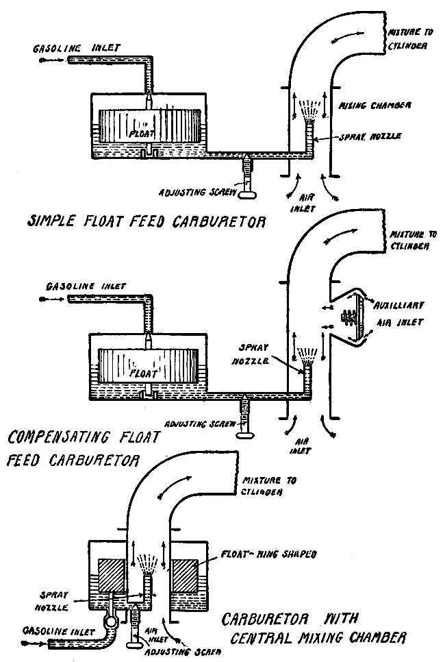
Fig. 19.—Carburetor Principles.
The principal parts of a float-feed carburetor are the float chamber and the mixing chamber, the gasoline flowing from the supply tank to [Pg 55]the float chamber, and from there to the mixing chamber, where it is combined with the air. The gasoline flows out of the float chamber through a small pipe, the end of which, called the spray nozzle, projects into the mixing chamber so that the current of air rushes past its tip (Fig. 19). When the inlet stroke is not being performed, and there is no air passing through the mixing chamber, the float in the float chamber keeps the gasoline at such a level that it stands just below the tip of the spray nozzle. In this condition the gasoline in both the float chamber and the spray nozzle is under atmospheric pressure; but when the pressure in the combustion space is reduced as the piston makes the inlet stroke, the pressure in the inlet pipe and mixing chamber is also reduced, and the gasoline will be forced out of the spray nozzle by the higher pressure in the float chamber. The passage in the tip of the spray nozzle is small, and the gasoline is broken up into fine drops as it spurts out, and in this condition is partly absorbed by the air and partly carried into the cylinder. By regulating the amount of gasoline that may pass out of the spray[Pg 56] nozzle, it may be adjusted to the volume of air flowing through the mixing chamber, so that any desired proportion may be obtained.
If the engine were to be run at a constant speed, the relative pressures on the gasoline in the float chamber and spray nozzle, and the quantity of gasoline forced out of the spray nozzle, would remain in correct proportion to the volume of air; but as the engine of an automobile is run at greatly varying speeds, the pressure in the mixing chamber is not constant, but varies to correspond. If the piston makes fifty inlet strokes a minute, the reduction of the pressure in the mixing chamber is more gradual than would be the case with the piston making two hundred inlet strokes a minute. The more rapidly the pressure is reduced, the greater will be the effect of the unchanging atmospheric pressure in the float chamber, and the more gasoline will be forced out of the spray nozzle. This will result in the presence of too much gasoline in proportion to the air, giving a mixture that is too rich. It is therefore necessary to provide an arrangement by which the pressure in the mixing chamber will[Pg 57] not be changed as the speed of the engine varies, and this is accomplished by the auxiliary air inlet, which is closed when the engine runs slowly, but opens to correspond with increasing speed (Fig. 19). The faster the engine runs, the more the auxiliary air inlet will open, to admit a correspondingly greater amount of air to prevent the pressure in the mixing chamber from being reduced below the point at which the required amount of gasoline is forced out of the spray nozzle.
The most rapid combination of the gasoline and air is secured by breaking the gasoline up into fine spray as it leaves the nozzle. In order to break the gasoline into fine particles, the tip of the spray nozzle is made with a fine opening, and often forms the seat for the gasoline adjusting valve, which is a needle-pointed rod that is screwed in or out to reduce or enlarge the opening; a further breaking up results from the placing of a metal cone, or the end of a rod, in such a position as to be struck by the gasoline as it flows out.
A carburetor with an auxiliary air inlet is provided with two points of adjustment, to[Pg 58] control the flow of gasoline from the float chamber to the spray nozzle, and to govern the admission of the auxiliary air. The flow of gasoline must be just sufficient to carburet thoroughly the air passing through the mixing chamber when the engine runs at low speed, and the auxiliary air inlet must open to correspond with increasing speed, to admit sufficient air to keep the pressure reduced to proper proportions.
The auxiliary air inlet may be operated either by the reduced pressure that permits the atmospheric pressure to open a valve, or by the governor of the engine, which opens the inlet as the speed increases, and closes it on slowing down. The first of these two types, called an automatic carburetor, is in most general use for automobiles, and is sufficiently satisfactory, but is not as accurate as the mechanically controlled type, which acts independently of pressure, and exactly according to the speed of the engine.
[Pg 59]
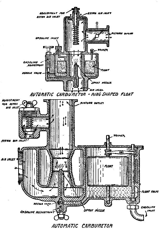
Fig. 20.—Automatic Carburetors.
Carburetors may be divided into two types, according to design: those in which the float and mixing chambers are side by side, and those [Pg 60]in which the mixing chamber passes through the center of the float chamber (Fig. 20). The former is along the lines of the first forms of float-feed carburetors, and the latter is of more recent design, its object being a more compact device, and one that is not affected by a change of level when the car is on a hill. Both have advantages and disadvantages, and the use of one as against the other is optional and a matter of opinion.
The carburetors illustrated are not of any particular makes, and are intended to show principles rather than construction.
In carburetors with a side mixing chamber the float is usually a metal box, the joints of which are as far as possible proof against leakage. Guides prevent it from having any but an up-and-down motion, and in thus moving it controls the gasoline inlet valve by a rod attached to it, or by a separate valve stem. In this carburetor a separate valve stem is used, and it is moved through the action of a rocker arm controlled by the float. This construction is usual when the gasoline enters the float chamber from the bottom, the flow being[Pg 61] permitted or checked by a needle valve. When the level in the float chamber drops as the gasoline runs out of the spray nozzle, the float sinks, and lifts the valve point from its seat. This admits gasoline from the supply tank, and the float in rising on it depresses the valve point, shutting off the flow. The gasoline adjusting valve is in the passage between the float and mixing chambers. The main or initial air inlet is in the side, the air being drawn through the mixing chamber, and past the spray nozzle. The auxiliary air inlet is a simple valve, opening inward, and held against its seat by a coil spring, the tension of which is adjustable. The pressure in the mixing chamber being reduced in accordance with the increasing speed of the engine, the valve is opened more and more as the atmospheric pressure against the outer surface of the valve overcomes the tension of the spring.
In carburetors with central mixing chamber the float is ring- or horseshoe-shaped, and usually made of cork, well varnished to prevent the absorption of the gasoline. The air enters at the bottom, passing directly to the[Pg 62] mixing chamber. The auxiliary air inlet is at the top, and is of the arrangement already described. The mixture passes out at the side, and may be controlled by a throttle, which may be a damper arrangement, as shown, or other device by which the quantity passing to the combustion space is at the will of the operator.
[Pg 63]
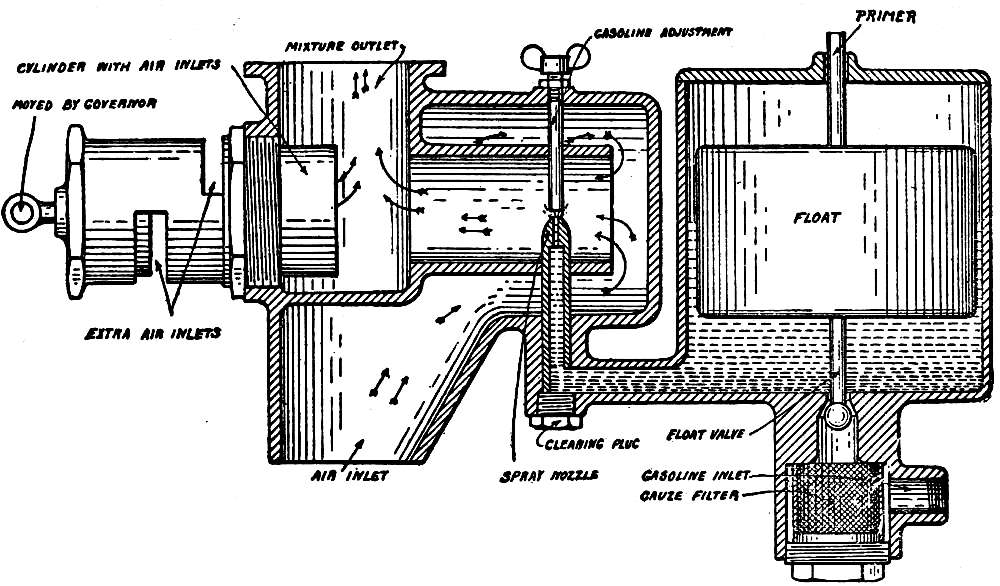
Fig. 21.—Mechanically Controlled Carburetor.
The float and mixing chambers of a mechanically operated carburetor are the same as in the side-float chamber type, the difference being in the control of the auxiliary air inlet (Fig. 21). This consists of a tube attached to the mixture outlet, within it sliding another tube moved by the governor as that expands or contracts with the speed of the engine. There are openings in the sides of both tubes, but when the sliding tube is at its inmost position these are not in line, and consequently are closed. When the governor acts with increased engine speed, the sliding tube is drawn out, and one or more openings come into line, air entering through them to the mixing chamber. The faster the engine runs, the larger become the openings, and in consequence the [Pg 64]greater is the amount of air that they admit. The illustration shows the ball type of gasoline valve, the ball on the end of the valve stem being drawn against its seat as the float rises.
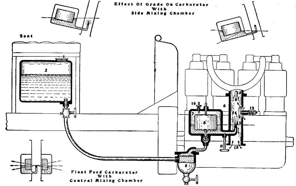
Fig. 22.—Float Feed Carburetor with Gravity Gasoline Feed. 1, Filling cap; 2, tank; 3, gasoline valve; 5, trap and strainer; 6, carburetor; 7, float chamber; 8, float; 9, float valve; 10, spray nozzle; 11, gasoline adjustment; 12, air adjustment; 13, throttle; 14, mixing chamber; 15, initial air inlet; 16, primer.
While these types are in practically universal use for automobile engines, there are other methods by which the proportions of the mixture may be maintained. In one form the gasoline drops on a funnel made of fine wire gauze, which is placed in the mixing chamber in such a manner that the air in entering passes through it. The liquid forms a film over the gauze, and is picked up by the air, as it is in a condition that permits it to evaporate rapidly. In surface carburetors air is forced through the gasoline tank, or through an absorbent material soaked with gasoline, and becomes thoroughly saturated. This mixture is then thinned with pure air until the desired proportion is obtained, when it passes to the combustion space. The objections to these forms arise from the clogging of the parts with the impurities present in gasoline, and while they give excellent results when new, they deteriorate rapidly and present such resistance to [Pg 66]the flow of the air current that they become useless.
There are two methods of supplying the carburetor with gasoline. Of these the most usual is the gravity feed, in which the tank is placed at a higher level than the carburetor, so that the gasoline flows down to it. The tank is usually placed under the seat, and the piping so arranged that the carburetor is the lowest point of the system. This method of feeding is satisfactory if the tank can be placed sufficiently above the carburetor to have the flow unaffected by an ordinary hill, but if it is not so placed, a steep ascent may tilt the car to such an extent that the carburetor is above the level of the gasoline in the tank, in which case the flow of course ceases.
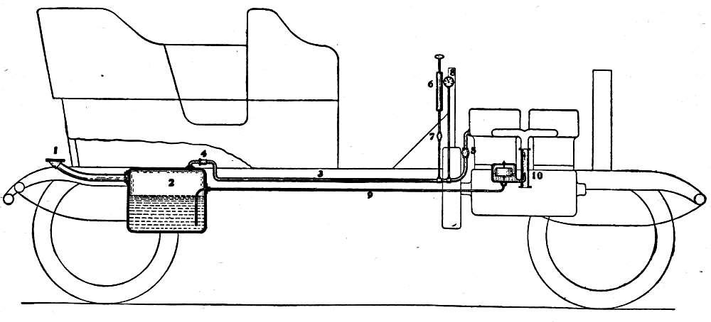
Fig. 23.—Pressure Feed Gasoline System. 1, Filling cap; 2, tank; 3, pressure pipe; 4 and 5, check and relief valves; 6, hand pump; 7, check valve; 8, pressure gauge; 9, feed pipe; 10, carburetor.
The pressure feed, which has been adopted on all high-grade cars, operates through the maintenance of pressure in the supply tank, the gasoline being forced out without regard to gravity. The tank is tight, so that the pressure cannot escape, and is connected by a long pipe of small diameter either with the combustion space of one of the cylinders or with the exhaust [Pg 68]pipe, so that the pressure of the burned gases is maintained in it. As the pressure cannot exist until the engine is running, a hand air pump is usually provided, by which a sufficient pressure may be produced in the tank to force out enough gasoline for starting. It is necessary to use as long a pressure pipe as possible, in order to prevent the possibility of flame passing through it to the supply of fuel, a long pipe, exposed to the air, cooling the gases to such an extent that they cannot ignite the gasoline.
The pressure pipe is always fitted with a check and relief valve, which acts as a safety valve in preventing the pressure in the tank from reaching a point at which the joints might be strained, and also retains the pressure which would otherwise escape when the engine stops. In some cars an auxiliary gasoline tank is provided on the dash, being fed by pressure from the main tank, and from which gasoline flows to the carburetor by gravity. The short distance of this tank from the carburetor and its elevation prevent the possibility of the flow being stopped by any tilting of the car short of an upset.
[Pg 69]
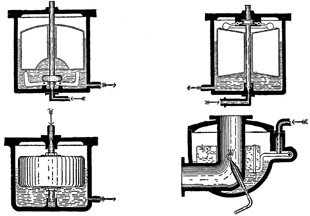
Fig. 23A.—Types of Float Valves.
[Pg 70]
Because of the liability of the presence of water in the gasoline, as well as dirt and grit, the gasoline line should be fitted with a strainer, or trap. This may be in any position, but it is usual to have it close to the carburetor, if not built into it. The simplest strainer consists of a number of thicknesses of fine wire gauze, so arranged that it may be easily taken out for cleaning. This will separate the dirt from the gasoline, and water may be caught in a trap, which is a pocket where the water, being heavier than the gasoline, may settle and be drawn off.
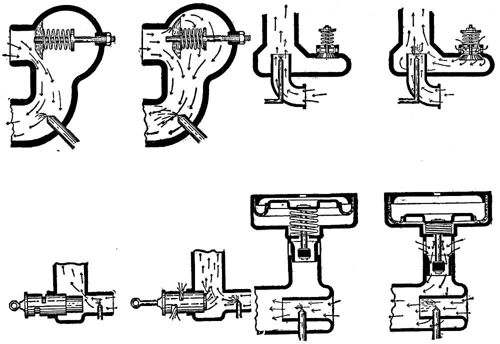
Fig. 23B.—Types of Auxiliary Air Inlets.
Practically all the carburetors on the market are combinations of a few forms of float valves, auxiliary air inlets, and spray nozzles. In addition to the forms shown in Figs. 20 and 21, the most usual float valves may be seen in Fig. 23A. In the first two types shown in this diagram, the float valve stems are separate from the floats, and are sufficiently heavy to shut off the flow of gasoline by their weight. In the third type, the gasoline enters the float chamber [Pg 72]from the top, and as the valve stem is attached to the float, the rising of the float results in the shutting off of the gasoline. The fourth type is in use on carburetors with central mixing chambers, the float being hinged to one wall of the float chamber. The loose valve stem is supported by the hinge, and rises to a seat in the valve when the gasoline is at the proper depth on the float chamber.
Fig. 23B illustrates the most usual forms of auxiliary air inlets. In the first type, the valve disk slides on the valve stem, and enlarges the size of the main air inlet. All of the air thus passes the spray nozzle. In the second type, the inlet for the auxiliary air is separate from the main air inlet, the two currents meeting in the mixing chamber, and the extra air diluting the rich mixture that is formed at the spray nozzle. This action is more correct in theory than that of the preceding type, and better practical results are obtained from it. These air valves are defective in opening and closing too abruptly, and in tending to vibrate rather than to remain open a fixed distance. The air inlet illustrated in the fourth diagram was designed[Pg 73] to overcome these faults. When the engine is not operating, the air inlets are closed by a hollow piston that is held up by a spring. The upper part of the piston rod carries a metal disk that is attached by a flexible leather washer to the walls of an upper chamber. The portion of the chamber above the disk is tightly closed, except for a small hole in the cover that provides the only communication between the atmosphere and the air confined in the chamber. When the engine runs at speed, the atmospheric pressure against the upper side of the disk is greater than the pressure against the lower side, and the disk is therefore forced downward against the action of the spring. The movement of the disk moves the piston, and as this latter slides downward it uncovers the openings and admits air. The small size of the opening in the cover prevents air from entering or leaving the chamber above the disk rapidly, and the movement of the piston is therefore steady and free from jerks. The third diagram illustrates two positions of a mechanically operated auxiliary air inlet, controlled by a governor.
[Pg 74]
The charge of explosive mixture in the combustion space is ignited, or set on fire, by an electric spark, and the apparatus for producing and controlling this spark is called the ignition system. It is with this part of the mechanism of an automobile that a novice has the greatest difficulty, for an electric current is usually regarded as being surrounded by an air of mystery. It does its work silently and without visible reason, and when it fails the average man is under the necessity of beginning at the beginning and examining all of the parts of the system because he has so little understanding of the why of it that he is unable to locate trouble in any but a rule-of-thumb method. The principles of electricity may be involved, but the production[Pg 75] of a current, its handling, and the uses to which it may be put are not difficult to understand.
Speaking broadly, the parts of the ignition system are the source of current, the arrangement in the combustion space at which the spark is produced, the device by which the instant when the spark passes may be controlled, and the circuit by which these parts are connected. Before going into a description of these, however, it is necessary to understand something of the nature and action of an electric current.
Every generator of electricity has two terminals, or poles, and the flow of current from one to the other is due to what may be explained as a difference in pressure between them. This difference in pressure is similar to that existing when two tanks, one full of water and the other empty, are connected by a pipe. The water will flow from the full to the empty tank as long as there is a difference in level, which is the same thing as a difference in pressure, the flow ceasing when the water in one tank is level with that in the other. When a path is provided between the two poles of the[Pg 76] generator, the current will flow from one to the other, always in the same direction, leaving by the positive pole and returning by the negative.
Because of this tendency to flow, the current may be made to perform work, for it will light a lamp, ring a bell, or do anything else within its power in order that it may flow from the positive pole of the generator to the negative. In this there is also a similarity to the two tanks, for if a water wheel is placed in the pipe connecting them, the flow of water from one to the other will operate it.
The path over which the current flows may be formed of any conductor of electricity, such as carbon or any metal; substances by which the current will not flow are called nonconductors or insulators, and those in most common use are rubber, china and glass, wood, wood fiber, mica, etc.
While all metals are conductors, some are better than others, the difference being in the resistance that they offer. A comparison illustrating resistance may be made between the friction presented to the flow of water by a[Pg 77] small pipe and by a larger one, the water flowing more easily through the latter than the former. In flowing, the current must overcome the resistance of the conductor, and in so doing will lose part of its strength and will heat the conductor, there being more loss of current and greater heat as the resistance increases.
It is obvious that in order to obtain a current of the greatest strength the conductor by which it flows must present the least possible resistance, and for this reason copper is used almost universally to convey the current from one place to another. A copper wire will carry safely a current that would heat an iron wire of the same size to the melting point. The resistance of a small conductor is much greater than that of a large one, so that the size of a conductor must always be considered in relation to the current that is to be conveyed.
A current of electricity may be measured, just as water flowing through a pipe may be measured, and by the same measurements of pressure and volume. The pressure under which the current flows is measured in volts, and the quantity that passes in amperes; there is[Pg 78] also a term for resistance, that being measured in ohms.
Because of the desire of the current to flow from the positive to the negative pole, the circuit must be so guarded that there may be no leakage, for if it can return to the generator without doing its work it will do so, taking any path that offers less resistance to its passage. Leakage is prevented by insulating the wires, which may be done by wrapping them with silk or cotton thread, or by coating them with rubber. The wire by which the current flows from the generator to its work is called the lead (pronounced leed), and the conductor by which it flows back, the return. The greatest care must be taken that there is no leakage from the lead wire in order that there may be enough current to perform the work; but when the current has done what was expected of it, any conductor that does not present too much resistance will serve to return it to its source.
While wire is sometimes used on ignition circuits for the return as well as the lead, the most usual method is to utilize the metal of the engine to return the current to its source.[Pg 79] The engine being made of iron, it is a conductor, and while this metal is not so good a conductor as copper, yet there is so much of it in an engine that its resistance need not be considered. This method is called grounding the return, the term coming from telegraphy, in which the dampness of the earth forms one of the conductors.
A grounded circuit requires careful insulation of the lead wire, for as it is very likely to come into contact with the metal of the engine, a break in the insulation would permit the current to leak and to return to the generator without doing its work, this condition being called a short circuit. Grounding the circuit saves wire and reduces complication; simplicity is important in automobile work, and a reduction of the parts much to be desired.
In the foregoing the word flow has been used in describing the action of an electric current in a wire, and there are so many points of similarity with the flow of water in a pipe that the term conveys a better idea than would technical expressions. Electricity, however, has neither substance nor weight, and cannot be[Pg 80] said to flow or to move in the strict sense of the words; but as flow is in general use, and is the most descriptive of the commonly understood words that are applied to it, it is made use of here.
A current of electricity may be generated either chemically or mechanically, and always at the expense of something else. A chemical generator produces a current at the expense of a metal, usually zinc, which is eaten by the chemicals in proportion to the amount of current delivered; a mechanical generator produces a current at the expense of the power that drives it.
Chemical generators are of two kinds, primary and secondary cells. While primary cells are of many forms, that called the dry cell is universally used for the ignition of automobile engines, being adapted to the purpose because there is nothing to spill, and may be used in any position. It consists of a zinc cup lined with some material of the nature of blotting paper, in which, but not touching it, is a stick of carbon, the space between being filled with absorbent material and broken bits of carbon[Pg 81] moistened with the proper chemical solution. The top of the cell is sealed to prevent evaporation, and thumb nuts on the projecting end of the carbon stick and the zinc cup form the terminals to which the wires are attached. The carbon being the positive pole and the zinc the negative, the current flows in that direction whenever a circuit is provided.
The dry cell gives a current at a pressure of about one and a half volts when new, the voltage dropping as the cell is used until it is exhausted, when the trifling cost of a new cell should not be considered in replacing it.
A better source of current than the dry cell is the secondary or storage cell, which is a reservoir rather than a generator. When a current of electricity is passed to it, usually from a lighting circuit, a chemical change takes place, the action being called the charging of the cell. When the change is complete, the cell is disconnected, and will then deliver a current because the parts of the cell that underwent a chemical change tend to return to their previous condition. The current that it gives off is practically equal to that by which it was[Pg 82] charged, and may be used steadily or intermittently until the cell is exhausted. It is made of prepared lead plates, which are placed in a hard-rubber or celluloid jar, with a cover to prevent the spilling of the solution with which the plates are covered.
The charging of storage cells must be done by an expert, for mishandling will ruin them, and it is far better to put this matter, as well as repairs, in the hands of a man who knows his business than to attempt it without the proper knowledge and appliances.
One point that the automobilist must watch, however, is the position and quality of the solution in the cells, called the electrolyte. The cells should always be full enough to have the plates well covered, and any loss by leakage or splashing should be made up, for the plates must not be exposed to the air.
Electrolyte is made by adding one part of chemically pure sulphuric acid to from three to four parts of distilled or rain water, adding the acid slowly and stirring constantly. The combination of acid and water generates heat, and care must be taken not to pour the water[Pg 83] into the acid, for the generation of heat would then be so sudden that the mixture would boil and splash, burning whatever it touched. By means of an instrument called a hydrometer, the density of the mixture may be ascertained, and when the proportions are correct the scale should read 1,200. Hydrometers are made with the instrument inside of a glass tube, one end of which has a spout, the other being fitted with a rubber bulb. By inserting the spout in the vent hole of the cell cover, the tube may be filled with electrolyte, the hydrometer showing whether or not it is of the correct density.
The cells should be tested every little while, and if the density is not correct acid or water should be added to make it so. Never probe inside of the cells with anything but a glass or hard-rubber rod, for metal would cause a short circuit between the two plates it touched, and probably ruin the cell.
The terminals of a storage cell are marked in order to distinguish them, the symbols being the plus (+) sign for the positive pole and minus (-) for the negative, these being universally used in this way on all electrical work.[Pg 84] In some makes of storage cells the positive pole in addition is painted red and the negative black.
A storage cell when fully charged gives a current at a pressure of about two and a half volts; the voltage drops as the cell is used, and when it gets down to 1. 8 volts it must be recharged. When a storage cell is discharged, it should be recharged immediately, for otherwise it will deteriorate.
One dry or storage cell does not give a sufficient current to supply the required spark, and several must therefore be used. The most usual method of connecting dry cells, and the only method of connecting storage cells, to form a battery, is to connect the negative pole of the first cell to the positive pole of the second, using a short length of insulated wire of sufficient size, the negative of the second to the positive of the third, and so on, until all of the cells necessary to supply the required current are used. This leaves the positive pole of the first cell and the negative pole of the last cell free to be connected into the circuit. The current obtained will have a pressure that is[Pg 85] as much greater than the pressure of one cell as there are cells in the battery; for instance, if there are four cells in the battery, of one and a half volts each, the voltage of the battery will be six volts. This method is called connecting in series (Fig. 24).
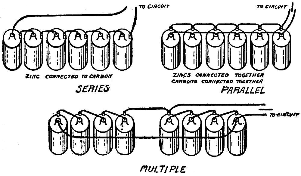
Fig. 24.—Battery Connections.
When the voltage of one cell is sufficient, and it is desired to increase the volume, or amperage, of the current, the cells may be connected in parallel, which is done by connecting together all of the negative poles by one wire, and all of the positive poles by another,[Pg 86] the two wires leading to the circuit. This increases the amperage as many times as there are cells.
If it is desired to connect the cells so that both the voltage and amperage are increased, the cells may be divided into two or more groups, with the same number of cells in each. The cells of each group are connected in series, and the free poles of the groups connected in parallel, which is called connecting in series-multiple (Fig. 24). This is a most satisfactory method of connecting the cells for an ignition circuit, for it gives a uniform current, and increases the life of the cells. The voltage of the current is equal to the voltage of one cell multiplied by the number of cells in one group, and the amperage that of one cell multiplied by the number of groups.
The action of a mechanical generator, which when driven produces a current of electricity, is due to magnetism, that being understood to be the power sometimes possessed by iron or steel to attract other pieces of iron or steel. Magnetism may be manifested either by permanent or electro-magnets. If a piece of steel[Pg 87] is magnetized—that is, made a magnet—it continues to be a magnet, for steel retains that property, while iron does not. A magnet made of steel is called a permanent magnet.
If a piece of iron is wound with insulated wire through which an electric current passes, the iron will become a magnet, and will remain so as long as the current flows. This is called an electro-magnet.
The two ends of a magnet are the positive and negative poles, and the positive pole of one magnet will repel the positive pole and attract the negative pole of another magnet. Between the two poles of a magnet there is a constant flow of what are known as magnetic lines of force, which may be made visible by laying a piece of paper over the two poles and scattering iron filings on it. The filings will form into curves from one pole to the other, showing the presence of these lines.
If a wire is moved across these lines of force, so that it cuts them, a current of electricity will be set up in it, and if the wire is wound into a coil and moved across the lines, the current will be as much stronger as there are turns of[Pg 88] wire cutting them. A mechanical generator consists of a coil of insulated wire, arranged so that as it revolves in the magnetic field each turn of wire cuts across the lines of magnetic force.
The magnet producing the lines of force that compose the magnetic field is called the field, and the revolving coil of wire the armature.
Mechanical generators for producing the current for an ignition circuit are of two types, magnetos and dynamos, the former being in much more general use than the latter. In a magneto the field is a permanent magnet, and in a dynamo it is an electro-magnet. The magnets forming the field of a magneto are bent into horseshoe shape, so that the poles are close together, and the armature revolves between them. The field of a dynamo is of similar shape, wound with insulated wire, the current that flows through it being generated by the dynamo itself; the field is strongly magnetized only when the dynamo is running.
The armature of either type is a piece of soft iron, with grooves cut in it lengthways, in which[Pg 89] the wire is wound; the winding thus being contrary to that of thread on a spool. The current generated in the wire of the armature is taken off by means of brushes, and connection is made through binding posts set in the base.
As the care of a mechanical generator requires a knowledge of electrical engineering, it is better to return it to the makers in case of injury, rather than to attempt to repair it without the necessary experience. (See Appendix.)
Practically all ignition circuits are provided with two sources of current, so that in case of the failure of one the other will be available, and either may be connected into the circuit by means of a switch. The simplest form of switch is a piece of flat spring brass, pivoted at one end so that the other may be swung from side to side to make contact with one or the other of two brass knobs, or switch points. One pole of each generator, usually the negative, is grounded, and the other connected to one of the points. The flat spring, or switch blade, is connected to the ignition circuit, so that when it is in contact with one of the points[Pg 90] the corresponding source is called on to supply the current. The blade may rest between the points, not touching either, in which case the circuit is broken, and no current flows.
[Pg 91]
While there are various methods by which an electric spark may be produced, but two are in use for automobile work, one being the high-tension or jump-spark system, and the other the low-tension or make-and-break system. The difference between these is in the pressure of the current, which in the first is great enough to enable it to jump from one terminal to another a short distance away, forming a spark as it passes. The pressure of the current of the low-tension system is not sufficient to permit it to do this, but when two terminals of the system are brought into contact so that the current may flow, a spark will form as they are separated.
In the make-and-break system, the igniter, which is the device in the combustion space at[Pg 92] which the spark occurs, is made with two metal points, one of which is stationary and the other movable, the latter being acted on by a cam, through a tappet. As the cam revolves, the tappet is lifted and the movable point brought into contact with the stationary; when the nose of the cam passes from under the tappet, the movable point is snapped away from the stationary through the action of a spring (Fig. 25). These points are so connected into the circuit that when they are in contact the current flows, the circuit being broken when they separate. Shortly before the spark is desired the movable point is brought into contact with the other so that the circuit is completed and the current flows, and they are separated at the instant when the spark is required to ignite the mixture, this occurring as they separate and break the circuit.
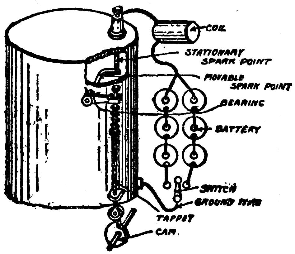
Fig. 25.—Make-and-Break Ignition.
The current that is supplied by the battery[Pg 93] is not capable of producing this spark, for it flows with large volume and small pressure—i.e., high amperage and low voltage—and it is necessary to transform it to a current of higher voltage and lower amperage, which is done by means of a primary induction coil. A coil of this description consists of a core made of a bundle of soft iron wires, around which is the primary winding, formed by winding several layers of insulated copper wire on it. The core becomes a magnet when a current of electricity flows through the winding, and ceases to be a magnet when the flow ceases, the magnetization occurring slowly on the completion of the circuit, and demagnetization instantly on the breaking of the circuit.
The influence of a magnet, as, for instance, its attraction for a piece of iron, is felt throughout a field the extent of which depends on the strength of the magnetization. When a loop of wire forming a closed circuit is placed in the magnetic field, a current of electricity will be set up in it whenever the strength of the field changes. If the strength of the field does not change, no current will be set up; but the greater[Pg 94] the change in strength, whether from strong to weak or from weak to strong, the greater will be the strength of the current. This principle is applied in the case of a coil, for the wire that forms the winding is in the magnetic field of the core, and a current is set up in it whenever the strength of the field changes. The strongest current will be set up, or induced, when the strength of the field changes from no magnetism to a degree when the core is magnetized to its fullest capacity or the reverse, and when the change occurs in the least possible time. The current that is set up will last only during the time when the change in strength occurs, ceasing to exist when the strength of the field is uniformly strong or weak. The more rapid the change, the greater will be the pressure of the current, but the shorter the period of its existence.
It is this induced current that forms the spark in the combustion space, the battery current serving only to establish the condition that will produce it. When the two points of the igniter come into contact and complete the circuit, the flow of the battery current through the[Pg 95] winding of the coil will gradually magnetize the core, and on the igniter points being separated, this flow through the winding will cease, the strength of the magnetic field dropping instantly from full intensity to practically nothing. This change induces a powerful current in the winding, which current in passing over the circuit causes a spark between the points of the igniter as they separate. The induced current is set up so instantaneously on the breaking of the battery circuit that the spark is usually considered as being that of the battery current, but, as stated, the battery current serves only to magnetize the core, the spark resulting from the current induced by its demagnetization on the breaking of the circuit.
A magneto is a machine that when driven generates an electric current, and is in almost universal use for this system of ignition. In many cars the system is so arranged that the driver has his choice between ignition by battery and coil, as described, and ignition by magneto, but the mechanical production of a current is so reliable that many automobile builders rely on the magneto alone. Magnetos[Pg 96] of the type used for ignition are described in the appendix.
The jump-spark or high-tension system of ignition depends on the production of a current at such a pressure that it can jump from one point to another through high resistance, such as is presented by air at ordinary or low temperature, and especially when compressed, the spark occurring as it passes.
This high pressure is obtained through the use of a secondary induction coil, which consists of a core and primary winding similar to those of the primary induction coil already described, and in addition has a secondary winding, formed by a great length of insulated copper wire, which to save bulk and weight is very fine, wound over the primary winding. The change in the strength of the magnetic field produced by the core affects this secondary winding, just as it affects the primary winding; that is, a current is set up in it at every change in the strength of the magnetic field, the pressure of the current depending on the greater[Pg 97] or less extent of the change, and the rapidity with which it occurs. The magnetization of the core takes place but slowly, for the particles of iron must absorb it one from the other, but the demagnetization occurs instantly; the current that is induced during the demagnetization is therefore the greater, and is the current that has sufficient pressure to jump across the gap.
The ignition system employing this coil consists of two distinct parts: the primary circuit, which magnetizes the core, and the secondary circuit, which leads to the combustion space the current that is induced in the secondary winding.
The primary circuit includes the battery or generator that supplies the current, the primary winding of the coil, a timer, and a vibrator.
The spark must occur in the combustion space only at the instant when the mixture is in a condition to be ignited, and it is obvious that only then is the secondary current required. As the secondary current results from the flow[Pg 98] of the primary current through the primary winding, a device must be included in the primary circuit to permit the current to flow and magnetize the core at this instant. This device is called a timer, or commutator, and is nothing more than a revolving switch operated by the engine, that completes the primary circuit at such times as the secondary current is required, and breaks the circuit when the secondary current has done its work in the production of the spark. Because ignition occurs but once in each cylinder during two revolutions of the crank shaft, the timer completes the circuit but once in that interval, and is placed on the half-time shaft that operates the exhaust valves. In its simplest form, a timer consists of a disk of hard rubber, wood fiber, or other insulating material in which is set a metal plate, mounted on the half-time shaft and revolving with it. A flat spring carried on a plate of hard insulating material bears against the edge of the disk, and during one revolution of the latter the metal plate set in it will be brought into contact with the spring (Fig. 26, first diagram). If one wire of the primary[Pg 99] circuit is connected to the metal plate of the disk and the other wire to the spring, it will be seen that the circuit will be complete when the revolution of the disk brings the two together, and broken when the further revolution of the disk separates them.
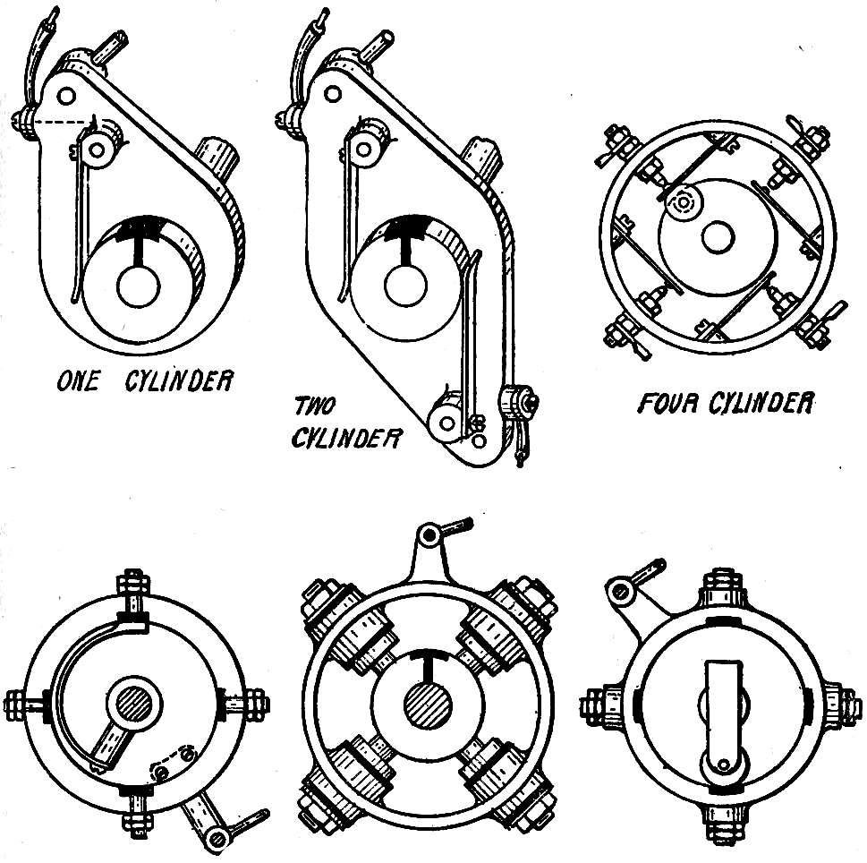
Fig. 26.—Types of Timers.
[Pg 100]
There is a great variety in the methods by which this result is secured, the chief essential being that the contact must be made as positively as possible in order that the resistance to the current in passing from one part of the timer to the other may be as low as possible, and broken equally positively. The number of contacts that the timer makes during one revolution depends on the number of cylinders of the engine, the revolving part touching two, three, four, or more springs or contact points on the stationary part as it turns. A timer for a two-cylinder engine is shown in the second diagram on Fig. 26, the third diagram being of a form of timer in which the revolving part is not connected into the circuit, but serves to bring together a spring and a contact point, the circuit being completed when they touch. A modern form of timer consists of a ring of hard rubber on the inside face of which are set the metal plates, while the moving part revolves within it, and may be a flat spring, or a plunger, or a roller, contact being maintained by a coil spring. The difficulty of attaching a wire to the moving part of the timer is overcome by[Pg 101] having its contact in connection with the half-time shaft, the current flowing from the contact on the stationary part to that on the moving part, and from there flowing by the half-time shaft to the ground connection of the battery, for, as all parts are of metal, the current can pass from the shaft to the ground connection through the bearings and the engine.
If the spark were always required to pass in the combustion space at the same point in the stroke of the piston, this could be secured by setting the stationary part of the timer in such relation to the moving part that contact would be made when the half-time shaft reached any desired point in its revolution. As it is necessary to change the point at which ignition occurs, however, the timer must be so arranged that it closes the circuit earlier or later, according to conditions. To effect this, the stationary part of the timer is so made that it may rotate around the shaft for about a half turn, and it is controlled by a lever on the steering column, which holds it in any desired position. If the stationary part is rotated in the direction opposite to that in which the[Pg 102] half-time shaft revolves, contact will be made and the circuit closed at an earlier point in its revolution than if it is rotated in the same direction. It must be remembered that the revolution of the half-time shaft, in operating the exhaust valve, revolves exactly in accordance with the crank shaft and the movement of the piston, and that as the moving part of the timer is attached to it, contact can be made at any desired point in the stroke of the piston by the position in which the stationary part is placed.
The secondary current occurs whenever the core is magnetized and demagnetized, and it is clear that the oftener the magnetization occurs the more constant will be its presence. The timer closes and opens the primary circuit, which results in the production of but two impulses of the secondary current, and as these are not sufficient to produce the necessary spark, additional means are employed to make and break the circuit while the timer makes contact. This is accomplished by means of a[Pg 103] vibrator, or trembler, which consists of a flat steel spring secured at one end, so that it may vibrate after the manner of a tuning fork. About midway between its ends the point of an adjusting screw touches it, and when the flat spring, or blade, vibrates, it springs away from this screw and returns to it, both screw and blade being tipped with platinum to offset corrosion. If one wire of the circuit is attached to the blade and the other to the screw, the circuit will be complete when the blade touches the screw, and broken when it springs away from it. In the early type of vibrator the blade was set in vibration by mechanical means. At the end of the blade was a weight, which rested on the edge of a cam, the blade then being out of contact with the adjusting screw (Fig. 27). During the revolution of the cam the weight dropped into a deep notch, thus setting the blade into vibration and the circuit being made and broken. This type has been almost entirely superseded by the magnetic vibrator, which is more rapid and accurate. In this the blade is so placed that its free end is close to the end of the core of the coil (Fig. 28). When[Pg 104] the timer makes contact and the current passes through the primary winding, the core becomes magnetized and attracts to it the free end of the steel blade, this movement drawing the blade away from the adjusting screw with which it was in contact. The vibrator is so connected into the primary circuit that the current flows from the battery to the adjusting screw, thence to the blade and through the primary winding; when the attraction of the blade by the core[Pg 105] draws it away from the adjusting screw, the circuit is broken, and the magnetism then ceasing to exist, the elasticity of the blade causes it to spring back to the screw, to make contact, and to be again attracted by the magnetism.
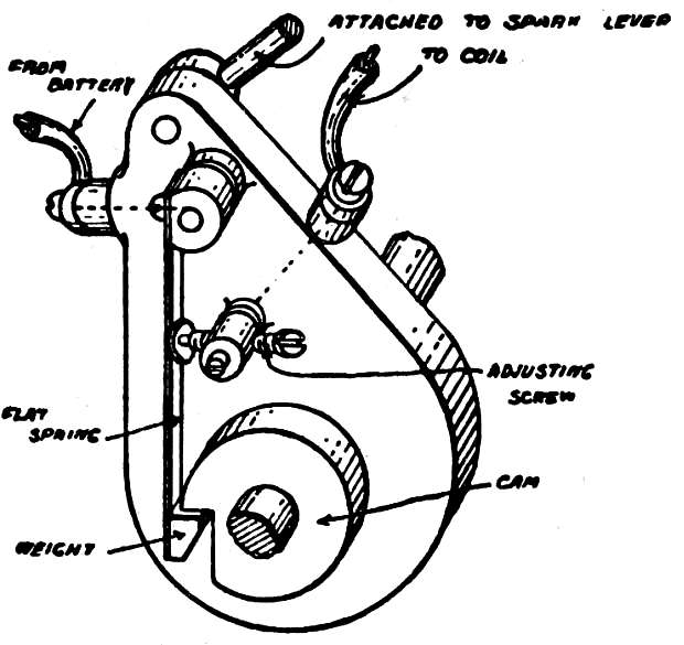
Fig. 27.—Mechanical Vibrator. When the weight drops into the notch on the cam, the flat spring touches the adjusting screw and the current passes.
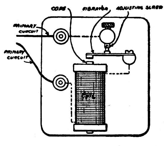
Fig. 28.—Magnetic Vibrator. When the magnetism of the core attracts the vibrator the contact is broken at the adjusting screw.
This action continues as long as the timer holds the circuit closed, and a wave of secondary current is set up in the secondary winding for every make and break that results. By means of the adjusting screw, the vibrations may be made long and slow, or short and quick, with a corresponding difference in the secondary current. As the object to be attained is the production of a spark that will ignite the mixture rapidly, the vibrator must be adjusted with this end in view; but it is also advisable to obtain the spark with the least possible expenditure of current, and with the least wear of the parts. The passing of the battery current through the primary winding establishes the condition that exists in the make-and-break ignition system, and the demagnetization of the core will set up an induced current that will result in a spark at the points where the circuit[Pg 106] is broken; that is, at the vibrator and timer contacts. This spark can be greatly overcome in the timer by packing it with vaseline, which, being an insulator, breaks down the spark in flowing between the contacts of the stationary and moving parts as they separate. If the vibrator contacts presented no resistance—an impossible condition—there would be no spark, but as they will always be slightly burned and corroded, the spark must be kept as small as the requirements of the secondary current will justify by the adjustment of the screw. In other words, adjust the vibrator so that it gives the best results in the production of the secondary spark with as little sparking as possible at the vibrator contacts.
The secondary circuit includes the secondary winding of the coil and the spark plug, which is the device in the combustion space at which the spark occurs. The spark plug provides two points of metal at a fixed distance apart, which are so connected into the circuit that the current must jump from one to the other in[Pg 107] order to complete its circuit. The secondary current, as well as the primary, may make use of the metal of the engine as a ground return, and one of the points of the spark plug is therefore in contact with the metal, being supported on a metal sleeve that is screwed into the cylinder. The other point must of course be insulated from it, for if it were not the current could pass from one to the other without jumping the space between them. The insulation is secured by a tube of porcelain or mica set in the sleeve, the lower end of a metal rod that passes through it being the required distance from the wire or projection on the sleeve (Fig. 29). This device must be strong enough to resist the pressure in the combustion space during the compression and power strokes, and must be unaffected by the intense heat.
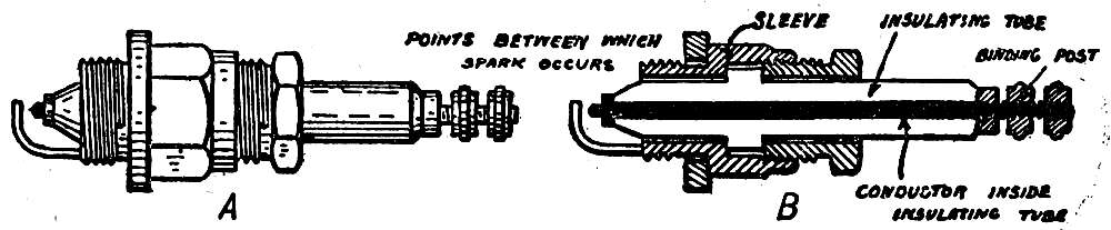
Fig. 29.—A, Spark plug; B, spark plug in section.
[Pg 108]
Fig. 30 shows the primary and secondary circuits of the jump-spark system, as applied to a one-cylinder engine, the light lines representing the primary circuit and the heavy lines the secondary. Each circuit forms a complete path by which the current passing over it may return to the point at which it started. In practice the wiring is simplified by the use of but one ground return for both circuits, the primary and secondary windings of the coil being connected at one point, and the secondary[Pg 109] current returning either through the timer as it makes contact or through the battery.
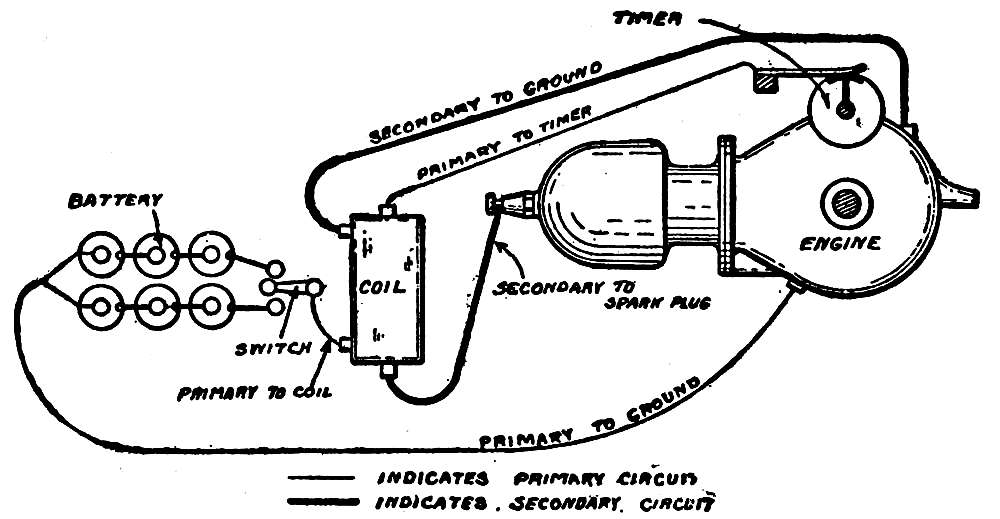
Fig. 30.—Ignition Circuit. Wiring diagram for one-cylinder engine, with coil, timer, and two batteries; coil with magnetic vibrator.
The flow of the primary circuit is from the battery to the switch, to the vibrator, which is built into the coil, through the primary winding and the timer contacts, whence it passes by the metal of the engine and ground wire back to the battery. The secondary circuit consists of a wire from the secondary winding of the coil to the spark plug, and back to its winding by the metal of the engine and a ground wire, which, as has been explained, may be the separate ground wire shown in the diagram, or the return that is common to both circuits.
The timer makes contact as the half-time shaft revolves, and the vibrator operates as long as the circuit is closed; while this occurs, the secondary current is set up, and the spark passes.
Included in the primary circuit and built into the base of the coil is a condenser which, while of such delicate construction that it is most inadvisable for the automobilist to attempt to examine or repair it, is of such advantage that[Pg 110] it should be understood. A current flowing in a circuit possesses momentum, and if the circuit is broken, the momentum will cause the current to flow across the break for a greater or less time, according to the pressure. This will produce a spark, and a spark at the vibrator as it breaks the circuit will not only burn away the contacts, but will prevent the instant demagnetization of the core. The passing of a spark between the vibrator contacts indicates that the current is still flowing through the primary winding, and that the core is still magnetized. The function of the condenser is to prevent sparking at the vibrator by absorbing the momentum of the current, and, what is more important, to cause the instant demagnetization of the core by the instant breaking of the circuit.
While it is usual to provide a multicylinder engine with one coil for each cylinder, it is possible to equip it with but one, in such a case a secondary distributer being used. This consists of two parts: a primary timer, and a somewhat similar device by which the secondary current induced in the coil is switched from cylinder to cylinder as it is required. For a[Pg 111] four-cylinder engine the timer has four contacts, as in the usual type; but the primary winding is connected to all of them, so that as the moving part of the timer revolves, the core of the single coil is magnetized four times to two revolutions of the crank shaft. A single wire leads the secondary current that is thus induced to the distributer, by which it is switched to the several cylinders. The moving part of the distributer rotates in unison with the moving part of the timer, making contact as it does so with contact pieces, each of which is connected to one of the spark plugs.
When the timer makes its contact the distributer is in position to pass the induced current to the proper cylinder, the connections being made in accordance with the firing order of the engine. While this system has advantages in that there is but one vibrator to adjust, the fact that the coil is operating for the greater part of the time makes it more liable to injury through heating and the consequent breaking down of its insulation.
[Pg 112]
The transmission of an automobile consists of those parts that transmit to the driving wheels the power developed by the engine.
Because a gasoline engine must be in operation before it can deliver power, a clutch is provided by means of which it may run free or be so connected that it drives the car, one of its two chief parts being attached to the engine and the other to the transmission. When the two parts are in contact, the transmission is driven, and when separated, the engine and transmission are independent of each other, and may be stationary or in motion. A clutch must be of such a nature that it does not apply the power of the engine instantly, but gradually,[Pg 113] so that the car starts slowly and without jerking. If the power were to be applied suddenly, the effort of starting the stationary car would either overcome the momentum of the engine and stop it, or would jerk the car into such sudden motion that it might be badly wrenched. By making the clutch so that it is permitted to slip when first applied, the part that is driven is gradually brought to the speed of the part that drives, when slipping ceases and the two make firm contact.
The most usual form of clutch is the friction cone, in which the fly wheel of the engine is utilized as the driving part, the rim being broad and thick, with its inner side funnel-shaped, or beveled. A metal cone that fits the bevel is carried on the end of a shaft of the transmission, the shaft at this point being square, to fit a square hole in the hub of the cone. This arrangement permits the cone to slide along the shaft while always revolving with it. When the cone is pressed to a seat in the fly wheel, which is accomplished by means of a heavy coil spring, the friction between its leather-covered surface and the surface[Pg 114] of the fly wheel causes the two parts to revolve together, and by its fit on the square shaft the transmission is set in motion, and through that the car. The clutch is thrown out of contact by means of a foot pedal that acts on a ring fitting in a groove around the hub of the cone; when the pedal is released, the spring forces the cone to its seat (Fig. 31). In order to support it, the end of the shaft carrying the cone projects into the hub of the fly wheel, where it rests in a bearing, this arrangement in no manner preventing the two parts from acting independently of each other.
In the reversed type of friction-cone clutch a funnel-shaped ring is bolted to the rim of the fly wheel and forms the seat, the cone fitting inside of it (Fig. 31). Depressing the pedal moves the cone toward the fly wheel instead of away from it, as in the regular type, and while there is no difference in the effect of one as against the other, the reversed type is more compact.
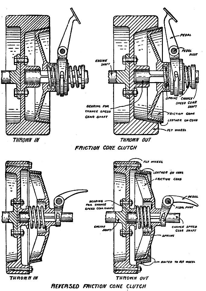
Fig. 31.—Friction Cone Clutches.
The multiple-disk clutch, which is rapidly coming into use, depends on the friction between the flat surfaces of metal when pressed [Pg 116]together. An experiment illustrating this is to place a silver dollar between two half dollars, and to press them together between the thumb and finger. It will be found that a light pressure is sufficient to produce friction that will make it difficult to revolve the large coin between the smaller ones.
The parts of a simple form of multiple-disk clutch, as shown in Fig. 32, are a flange on the engine shaft, a smaller flange with a square-hole, square-shaft arrangement on the transmission shaft, and large and small rings placed alternately. The large rings are driven by the large flange, fitting loosely on pins, or studs, projecting from it, and the small rings are similarly attached to the transmission shaft. The openings in the large or driving rings are large enough to contain the studs carrying the small rings, so that when the parts are assembled the outer surfaces of the small or driven rings are in contact with the inner surfaces of the driving rings. A heavy coil spring is arranged to press the small flange toward the flange on the engine shaft, binding the rings that it carries between the driving rings, and the latter are[Pg 117] often faced with leather to increase the friction between them. When the small flange is released from the pressure of the spring by depressing the pedal, the driving and driven flanges with their rings are independent of each[Pg 118] other, and the engine may run free while the transmission shaft is stationary or revolving. A clutch of this type is incased and runs in oil, which prevents the rings from gripping suddenly; when the pressure of the spring is applied, the oil is gradually squeezed out from between them, and the slipping of the driving and driven rings is reduced as they are forced into contact.
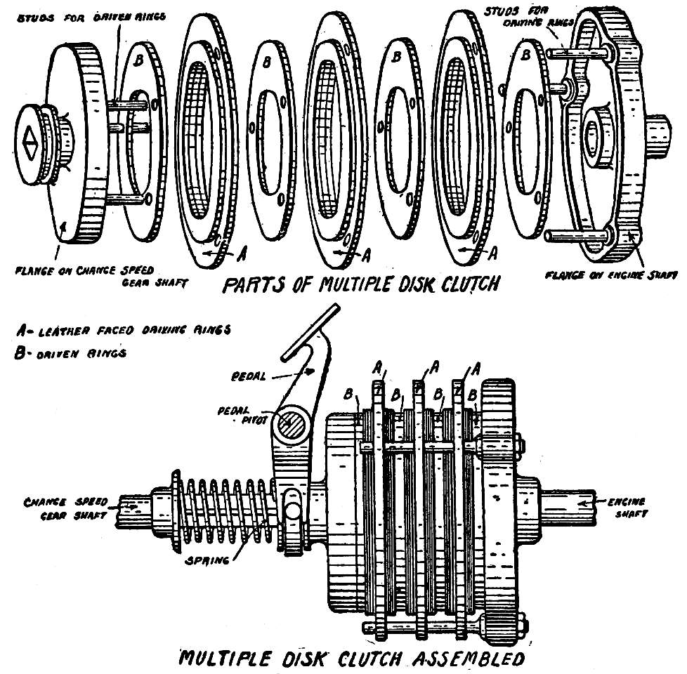
Fig. 32.—Multiple Disk Clutch.
An internal-expanding clutch consists of a broad ring, or drum, against the inner surface of which bear two pieces of metal shaped to fit. The pieces of metal, or shoes, are pivoted together at one end so that they may be moved in or out, after the manner of the handles of a pair of scissors; when open they bear against the inside surface of the drum, and when closed they are free from it. The drum is attached to the engine shaft and the shoes to the transmission shaft, the friction between them being so great that the transmission shaft is carried around as the drum revolves. The shoes are kept in contact with the drum by a coil spring, the depression of a pedal releasing them from its pressure.
[Pg 119]
The change-speed mechanism, to which the clutch transmits the power of the engine, is to the engine what a block and tackle is to a man who lifts a heavy weight, and is necessary because of the varying resistance to the movement of the car in traversing steep, rough hills and smooth avenues. A change-speed mechanism may be defined as an arrangement by which the relative number of revolutions of the crank shaft and driving wheels may be altered to suit conditions. If the driving wheels revolve but once while the crank shaft makes twelve revolutions, the car will move at one sixth the speed that it would have if the wheels revolved once to every two revolutions of the crank shaft, but it will have six times the ability to overcome the resistance presented by a hill or sandy road.
If a gasoline engine were so connected that the relative number of revolutions of the crank shaft and wheels could not be changed, a slowing down of the car through the resistance presented by a rough hill would slow the engine[Pg 120] to correspond, and as speed is an important factor in the power that the engine delivers, it would be prevented from doing the work of which it is capable at the time when it was most necessary. By means of the change-speed mechanisms in most general use, the relative number of revolutions of the crank shaft to one of the wheels may be varied to from two to eighteen, the former giving the car high speed over a smooth road, and the latter slow speed, but greater ability to overcome hills and heavy roads.
To attain this result, gears are used. If two gears having the same number of teeth are in mesh, they will make the same number of revolutions, and the force with which the driven gear will revolve will be the same as that of the driving gear, less the friction of the teeth. If the driven gear has twice the number of teeth of the driving gear, it will revolve at half the speed, but with twice the force.
The forms of change-speed mechanism most largely used are based on this principle, which is so applied that the gear driven by the engine may be in mesh with a gear that has many[Pg 121] more teeth and revolves much slower in consequence, or a gear that has possibly one and a half times the number of teeth, or a gear that has the same number of teeth, and therefore revolves at the same speed. The sliding-gear mechanism takes its name from the arrangement by which the changes in the combination of gears is effected by sliding them along a shaft, to mesh with other gears on a shaft driven by the engine.
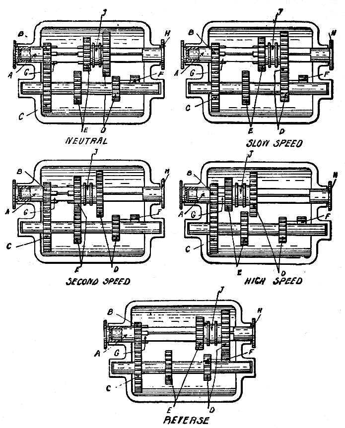
Fig. 33.—Sliding Gear—Progressive Type. A, Sleeve driven by engine; B, gear on sleeve; C, gear on countershaft; D, low-speed gears; E, second-speed gears; F, idler for reverse; G, clutch for high speed; H, connected to rear wheels; J, gears sliding on square shaft.
The driver changes the gears by moving a lever that in the progressive type moves forward by degrees to move the car on the slow speed, the intermediate speeds, and the high. A typical arrangement of the progressive type of sliding change-speed mechanism is shown in Fig. 33. The power of the engine is transmitted to a short, hollow shaft, called a sleeve (A), which carries a gear (B) that is in permanent mesh with a gear (C) on the end of the countershaft. Parallel to the countershaft is another shaft, one end of which is held in a bearing in the hollow sleeve; while the sleeve supports this shaft, the two may revolve independently of each other. The second shaft is square, [Pg 123]or of such a construction that while the two gears that it carries may slide along, they revolve with it. The gears on the square shaft are of different sizes, and in sliding on it come successively into mesh with gears carried on the countershaft. Because of the gears between them, the countershaft revolves when the engine revolves the sleeve; but the speed of the square shaft depends on the combination of gears in mesh between it and the countershaft. When the sliding gears are in such a position that they are not in mesh with the countershaft gears, the square shaft is independent of the countershaft, and may revolve or be stationary, the gears then being in the neutral position. When the sliding part is moved so that its largest gear is in mesh with the smallest of the countershaft gears (D), the square shaft will revolve at a slower speed than the countershaft, because its gear is larger than the one driving it. Again sliding the moving part will separate these gears, and bring the next pair (E) into mesh, the square shaft then moving at a higher speed, but still slower than the countershaft because[Pg 124] of the difference in the size of the gears. Sliding the moving part still farther along the shaft will disengage the second-speed gears and engage the high speed, in which the square shaft revolves at the speed of the sleeve and crank shaft, this being effected by locking the moving part to the sleeve by means of a clutch (G). This clutch consists of several fingers projecting from the moving part, corresponding to the spaces between similar fingers on the end of the sleeve. The locking together of the square shaft and sleeve gives what is known as the direct drive, which is of comparatively recent development; many designs of sliding gears still use a third pair of gears which, being of the same size, give the square shaft the speed of the crank shaft. By the use of the direct drive, the power of the engine is directly applied to the square shaft, avoiding the loss that occurs through the friction of the teeth of the gears.
The revolution of the square shaft is transmitted to the driving wheels, the speed of the car therefore corresponding to the speed at which the square shaft is driven by the gear[Pg 125] combinations between it and the countershaft. To obtain the reverse, which enables the car to be backed without reversing the engine, a third gear is introduced between the low-speed gears of the square shaft and countershaft. When two gears are in mesh, they revolve in opposite directions, but when one of them is in addition meshed with a third gear, the first and third will revolve in the same direction, and opposite to the direction in which the middle gear revolves. When the car is going forward, the square shaft and countershaft revolve in opposite directions, but when the reverse gear is introduced between them, the square shaft is revolved in the same direction as the countershaft, reversing the rotation of the driving wheels.
The ends of the teeth of the gears are chisel-shaped, instead of being flat, as in ordinary gears, so that they will go into mesh easily.
The greatest economy in the operation of a gasoline engine results from its running at as nearly constant a speed as possible, and the gear is therefore changed when the resistance of the road to the movement of the car decreases[Pg 126] the speed of the engine, or permits it to increase.
The selective type of sliding change-speed mechanism as shown on Fig. 34 is in use on many of the high-grade cars, and its control differs from that of the progressive type described in that the lever has only a short movement forward and back, and in addition may slide sideways. To the lower end of the lever is attached a shaft that rocks in its bearings as the lever is moved forward or back, and slides lengthways when the lever is moved toward or away from the car.
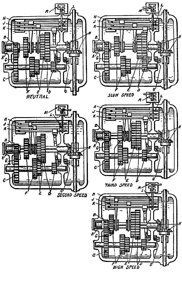
Fig. 34.—Selective Type. A, Sleeve driven by engine; B, fixed gear on sleeve; C, fixed gear on countershaft; D, low-speed gears; E, second-speed gears; F, third-speed gears; G, clutch for direct drive; H, rod and arm for third-speed and direct drive; J, rod and arm for low and second speeds; K, rod and arm for reverse, L, rocking-shaft finger in groove; M, guide plate and control lever; N, bevel gears on square shaft and jack shaft; O, idler gear for reverse.
The arrangement of the countershaft and square shaft is the same as in the progressive type, but there are two sets of sliding gears instead of one, and these are moved by means of arms that extend from rods sliding in bearings at the side of the gear case. When these rods are slid endways, the gears attached to their arms slide on the square shaft to correspond, and go in or out of mesh with the countershaft gears. Across the ends of these rods are grooves, which when the gears are in the neutral position are in line with the rocking shaft attached [Pg 128]to the control lever. From the inward end of the rocking shaft a finger (L) projects downward into the groove; when the grooves are in line, the rocking shaft may be slid endways, the finger passing from one groove to the next without affecting the rods. When the shaft is rocked, however, the finger in engaging one of the grooves slides the rod endways, shifting the gears controlled by its arm. Moving the control lever into such a position that it may enter the middle slots of the guide plate (M) slides the rocking shaft so that its finger projects into the groove of the central sliding rod (J), and if the control lever is then pushed forward so that it enters the front half of the slot, the sliding rod will be moved by the finger in the opposite direction, and the low-speed gears (D) will be brought into mesh. Bringing the lever back to the central position will separate the gears, and moving it to the back half of the slot will slide the same gears in the opposite direction, meshing the second-speed combination (E). Moving the control lever outward so that it is in line with the outside slot brings the finger into the groove of[Pg 129] the sliding rod (H) that moves the third and high speeds (F and G), the latter being direct drive, and the reverse is obtained through the movement of the sliding rod (K) that is engaged by the finger when the control lever is in the inside slot. The movement of this rod brings a third gear (O) into mesh with the low-speed gears on the square shaft and countershaft, and the rotation of the countershaft is reversed.
While this type is in general use, the gears are often so arranged that the direct drive combination is reached when the control lever is in the third-speed position, the gears meshed by the fourth-speed position driving the square shaft at a still higher speed. This high speed can only be used for running under the best road conditions.
The advantages of the selective type over the progressive are the shorter movements of the control lever and the ability to pass from one speed to any other without the necessity of first meshing and unmeshing those between, or, in other words, there is a neutral position between every combination of gears, and from neutral[Pg 130] any desired combination may be obtained directly without reference to the others.
In starting up a car fitted with either of these types of change-speed mechanism, it is necessary to withdraw the clutch before sliding the gears, and this is also necessary in changing from one combination to another. The square or corresponding shaft of a change-speed mechanism is always connected with the driving wheels, and is at rest when the car is standing. With the engine running, the countershaft will be revolving, and it will obviously be difficult to slide the stationary gear into mesh with a gear that is revolving. When the clutch is withdrawn, the countershaft moves only through momentum, and will be brought to a stop by the contact of the teeth of the sliding gear as that is moved against it, the two then easily going into mesh. The clutch is then thrown in slowly, and will bring the speed of the countershaft to the speed of the crank shaft.
When the car is moving, sliding the gears without first withdrawing the clutch will bring together two gears that are revolving at different speeds, and as it is necessary for them[Pg 131] to be rotating equally in order that they may mesh, either the speed of the car must be changed to bring the speed of the gear on the square shaft to that of the countershaft gear, or the speed of the engine must be changed to bring the countershaft gear to the speed of the gear on the square shaft. If the change is from a low to a higher speed, the countershaft will be moving much faster than the square shaft, and their gears being brought into contact will result in the slowing of one and speeding up of the other until the speeds are the same, but in so doing the ends of the teeth will grind against each other, resulting in the wear of the chisel-pointed ends, if not in the breaking of the teeth. Withdrawing the clutch obviates this difficulty, for it frees the countershaft, permitting its gear to take the speed of the square-shaft gear without wear or damage, and when the change is made, the slow engagement of the clutch brings the speed of both to that required by the crank shaft.
[Pg 132]
While the planetary type of change-speed mechanism, which is in extensive use for runabouts and light commercial wagons, also employs gears, their arrangement is along different lines. The first three diagrams in Fig. 35 serve to illustrate the principle.
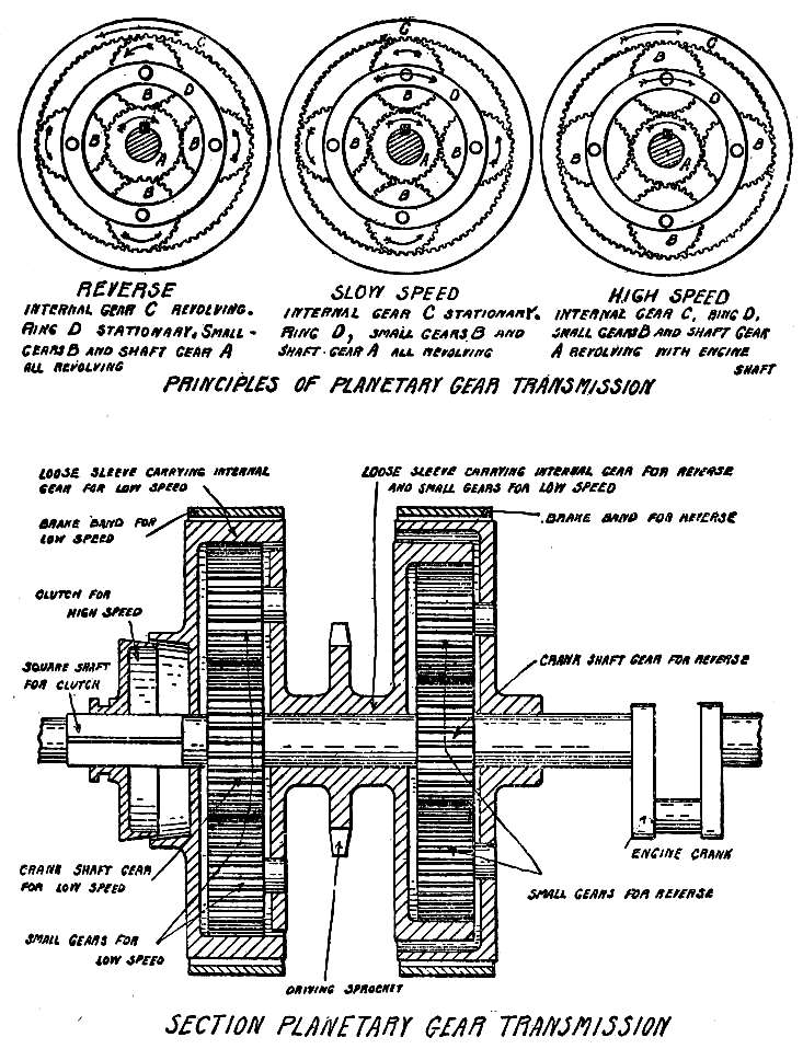
Fig. 35.—Planetary Type.
The gear A in these diagrams is attached directly to the crank shaft, and in mesh with it are four other gears (B) of the same size. Surrounding them is an internal gear (C), this being a ring with teeth cut on its inner face, the four gears meshing with it. The shafts, or studs, on which the four gears revolve are supported by a metal ring (D), which maintains the gears at equal distances from each other. The first diagram shows the mechanism in the reverse [Pg 134]position, for driving the car backward, the car being driven by the internal gear. To have the internal gear revolve in the direction opposite to that of the crank shaft, as is necessary, the ring supporting the four gears is held stationary, with the result that as the crank-shaft gear revolves the four gears are revolved on their studs. As these gears are in mesh with the internal gear, that is revolved, and moves in the same direction as the four gears and in the opposite direction to the crank shaft.
For the low-speed forward, the ring is released and the internal gear held stationary, the car now being driven by the ring instead of by the internal gear. If the four gears were free from the internal gear, they and their ring would revolve with the crank-shaft gear without rotating on their studs, but being in mesh with the internal gear, they roll around it as a wheel rolls along the ground, rotating on their studs. A simple experiment that will illustrate this motion is to crook the forefinger around a napkin ring or similar object, placing a pencil between it and the finger, and revolving the ring with the other hand. The finger being stationary, the pencil,[Pg 135] which is revolved in the opposite direction to the ring, will roll along it. In this the napkin ring represents the crank-shaft gear, the pencil one of the four gears, and the finger the internal gear. As the four gears roll around, the ring moves also, for it is carried by the studs on which the four gears revolve. If each of the four gears has fifty teeth, and the internal gear two hundred teeth, each gear must make four revolutions in order to roll around the internal gear to the point where it started. The crank-shaft gear also having fifty teeth, it revolves at the same speed, and as four revolutions of the four gears are necessary in order that they may roll completely around the internal gear, the crank-shaft gear will make four revolutions in the same time. The ring moves with the four gears, and revolves once around the crank shaft in the same time. As the car moves according to the rotation of this ring, it will go at one quarter the speed that it would make if the wheels were directly connected with the crank shaft instead of with the ring.
For the high speed, the internal gear and the ring are locked to the crank shaft so that all[Pg 136] revolve together, the wheels being driven by either the ring or the internal gear.
In these diagrams the drive of the wheels is supposed to be shifted from the internal gear to the ring, which is not a practical arrangement, and the planetary change-speed mechanism as applied to an automobile is shown in the lower diagram in Fig. 35.
In this there are two sets of crank-shaft gears, gears and rings, and internal gears, one set being for the reverse and the other for low and high speeds. Between the two crank-shaft gears is a loose sleeve, one end of which forms the internal gear for the reverse, and the other end the ring supporting the studs on which revolve the four gears for the low speed. The sprocket for the chain drive to the rear axle is carried on this sleeve. Two more loose sleeves are on the shaft, one forming the ring on which revolve the four gears for the reverse, and being extended to form a brake drum outside of the internal gear, and the other carrying the internal gear for the low-speed combination, its outside face serving as a brake drum.
To obtain the reverse, a brake band is tightened[Pg 137] on the drum of the reverse combination, which holds stationary the ring supporting the four gears, giving the result shown on the first diagram of the four gears revolving on their studs, and rotating the internal gear in the direction opposite to that of the crank shaft. The sleeve bearing the sprocket is thus revolved, and the car backs.
For the low speed, the reverse brake band is loosened, and the internal gear of the low-speed combination held stationary by the tightening of the brake band surrounding its drum. The revolution of the crank-shaft gear causes the four gears to revolve on their studs and to roll around the internal gear, revolving the ring and the sleeve bearing the sprocket, which now turns in the direction opposite to that resulting to the application of the reverse, or in the same direction as the crank shaft.
For the high speed, a clutch is engaged that locks the internal gear to the crank shaft, and the four gears then being held between these two are carried around with them, and the sprocket rotates accordingly. When this combination is used, none of the gears are in motion,[Pg 138] all revolving with the crank shaft but not on their studs.
The planetary change-speed mechanism gives excellent results for light work, but having only two speeds forward is not adapted to high-powered cars. As the speeds result from the tightening of brake bands on the drums, there is no danger of damaging the gears by mishandling, for the brakes will slip before the teeth will give way. The brakes, which are leather-lined strips of steel, require attention from the wearing of the leather, and the slipping that results from oil working in between them and their drums. No foot clutch is necessary, for the tightening and loosening of the brake bands is controlled by a lever; in some designs, the reverse is applied by means of a foot pedal, and this may be used in braking the car.
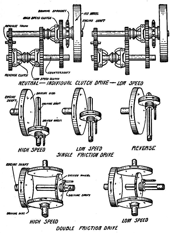
Fig. 36.—Individual Clutch and Friction Drive.
The individual-clutch type of change-speed mechanism consists of two shafts, one being an extension of the crank shaft, and the other parallel to it (Fig. 36). On the crank shaft is a sleeve bearing the sprocket and a gear, this sleeve being so arranged that it may revolve loosely, or be locked to the crank shaft and [Pg 140]made to revolve with it by a clutch. The crank shaft in addition bears two fixed gears, one being for the low speed and the other for the reverse. On the countershaft is a fixed gear in mesh with the gear carried on the sleeve on the crank shaft, and two loose sleeves bearing gears that are in mesh with the fixed low-speed and reverse gears on the crank shaft. These sleeves are provided with clutches by which they may be locked to the countershaft to revolve with it, or disconnected from it. When the three clutches are disengaged, the crank shaft in revolving carries with it the fixed low-speed and reverse gears, the sleeve bearing the sprocket and gear remaining stationary. The sleeves on the countershaft revolve because their gears are in mesh with the fixed crank-shaft gears, but the countershaft remains stationary. In engaging the low speed, the clutch is thrown in, forcing the countershaft to revolve with the fixed gear, the fixed gear on the countershaft then revolving the gear and driving sprocket carried on the sleeve on the crank shaft. Because of the difference in the size of the gears, the countershaft will revolve[Pg 141] at a slower speed than the crank shaft, and the driving sprocket will make but one revolution while the crank shaft makes several. This it is free to do, for the sleeve carrying the sprocket is in no way connected with the crank shaft. For the high speed, the low-speed clutch is withdrawn, and the driving-sprocket clutch engaged, causing the sprocket to revolve with the crank shaft.
The reverse is caused by the introduction of an idler gear between the gears of the crank shaft and countershaft, by which the movement of the latter is reversed.
The application of the friction type of change-speed mechanism to automobiles is recent, and is giving good results for light work. It consists in its simplest form of a heavy disk carried on the engine shaft, on the face of which runs a wheel sliding on a square shaft, so that the two may be in contact at any point from the edge to the center of the disk (Fig. 36). When the wheel is at the center of the disk it is not moved, and the number of speeds at which the square shaft may be driven in relation to that of the disk varies from nothing to the limit,[Pg 142] which is obtained when the wheel is in contact with the outer edge of the disk. For the reverse, the wheel is moved across the center of the disk, where it is revolved in the opposite direction.
Another form of friction drive provides two driving disks, the wheel bearing against both, so that its movement is more positive, and there is less chance for slipping.
From the change-speed mechanism the power is passed to the driving wheels by the final drive.
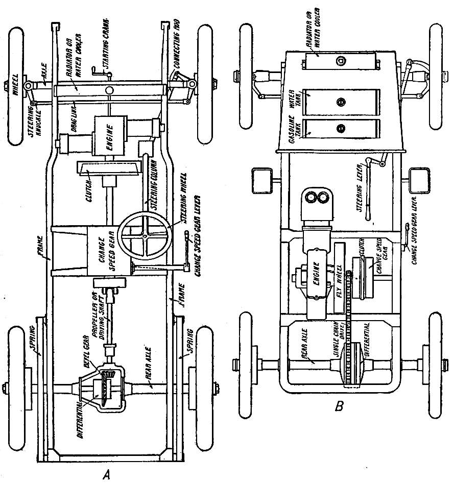
Fig. 37.—A, Propeller or driving-shaft drive; B, single-chain drive.
In the most usual construction the engine is so placed that the crank shaft is at right angles to the axle, and it is therefore necessary to change the direction in which the power acts, which is done by means of bevel gears. In ordinary spur gears the teeth are parallel to the shaft, and the two shafts that carry them are parallel, while in bevel gears the teeth are at an angle, and the shafts may be at right angles to each other. In Fig. 37 the diagram of the single-chain drive illustrates a car in which the engine is in the center of the frame, [Pg 144]and as the crank shaft is parallel to the axle, the power may be directly applied. In the illustration of the propeller or driving-shaft drive the crank shaft is at right angles to the axle, and the power is turned by means of the bevel gears at the rear axle.
The single-chain drive can only be used for light cars, and is usually applied in connection with a change-speed mechanism of the planetary type.
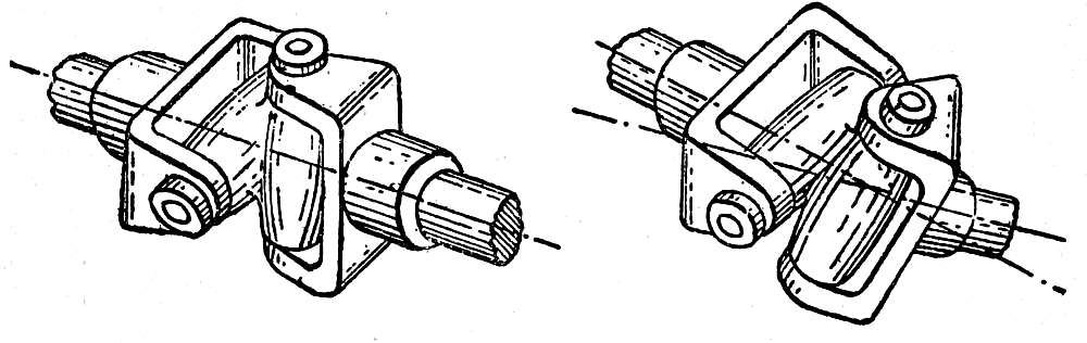
Fig. 38.—Typical Universal Joint.
The propeller-shaft drive requires the use of universal joints, which are devices that permit one shaft to drive another, even though they are at an angle with each other. A typical universal joint is illustrated in Fig. 38. The ends of the shafts bear yokes, the ends of which are pivoted to a block of metal of + shape. When the two shafts are in line, the joint will [Pg 146]force one to rotate with the other, and this will not be prevented if the two are out of line, for then the pivots will act, the + swinging on its pivots in the yokes.
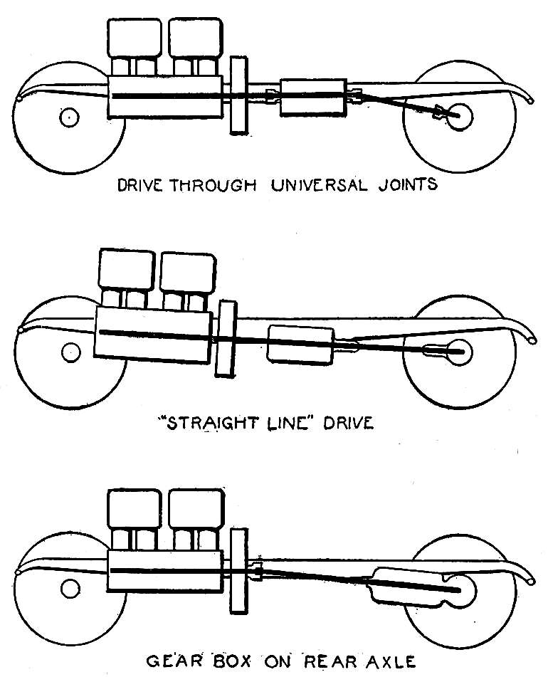
Fig. 38A.—Types of Shaft Drives.
The change-speed mechanism is carried on the frame of the car, and is therefore supported by the springs, but the axle end of the driving shaft follows the axle as that follows the inequalities of the road. One end of the propeller shaft is therefore comparatively stationary, while the other is in constant motion, and if the shaft were inflexible it would be jammed in its bearings and twisted out of line. This is prevented by the universal joints with which the shaft is provided, there being one and often two in the shaft, and usually one between the clutch and change-speed mechanism.
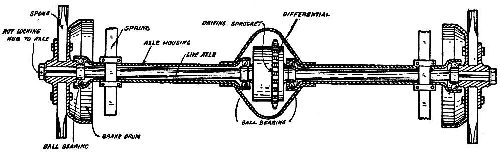
Fig. 39.—Live Axle—Non-Floating Type.
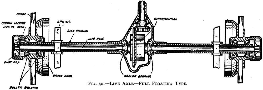
Fig. 40.—Live Axle—Full Floating Type.
The single-chain and driving-shaft drives require the use of a live axle, which is an axle that revolves with the wheels. The simple type of live axle consists of the shaft to which the wheels are attached, and the housing that contains and supports it (Fig. 39). This axle is continuous, and usually has square ends that fit into the square hubs of the wheels so there [Pg 148]may be no slipping. The second diagram in Fig. 40 shows a live axle of the floating type, in which the revolving part serves only to turn the wheels. The housing is extended, and the wheels run on its ends, the driving part projecting beyond the housing and having square ends that are secured to the outside of the hubs by square caps. The wheels thus run on the housing, which takes the weight of the car from the driving part. A live axle must be divided into two parts in order that a differential gear may be fitted, and the housing must therefore be strong enough to support the weight and prevent sagging. The efficiency of a bevel gear is greatly reduced if the teeth are not in their exact mesh, and sagging of the axle will throw them out to such an extent that they will be noisy, and wear rapidly. The floating type of live axle, in relieving the driving part of the weight, has a great advantage over the simple type, and is in general use.
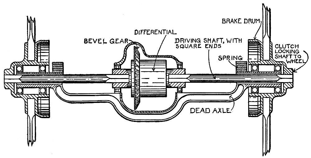
Fig. 40A.—Dead Axle with Driving Shaft. Axle supports Bevel Gear and Differential. The Driving Shaft is supported in Bearings at the Differential end, and drives the wheels through clutches in the hubs.
With the driving-shaft drive it is necessary to use a torsion rod, which extends from the gear case, or a crosspiece of the frame, to the rear axle. The necessity for this is the tendency [Pg 150]of the driving bevel gear to roll around on the driven bevel gear rather than to revolve it. If it were not for the torsion rod, there would be a continual strain on the parts because of the tendency of the axle housing to revolve around the axle, instead of the axle being revolved inside of the housing. The torsion rod has a flexible joint at one end, that permits it to give as the axle follows an uneven road surface, but it retains the housing in the correct position, preventing the bevel gears from getting out of line (Fig. 41).
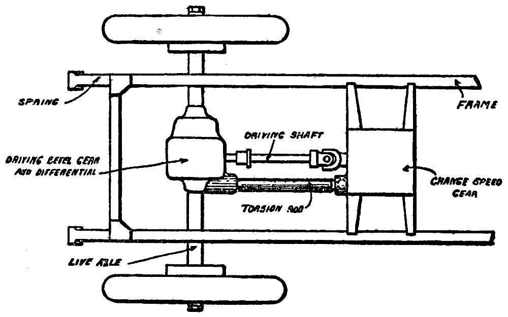
Fig. 41.—Torsion Rod.
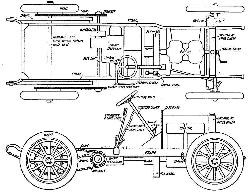
Fig. 42.—Double Side-Chain Drive.
In Fig. 42 is shown a car with double-chain drive, in which the bevel gears that change the [Pg 152]direction in which the power is applied are contained within the gear case that incloses the change-speed mechanism. As will be seen from Fig. 34, the bevel gears connect the square shaft with the jack shaft, which is a shaft passing across the car, and bearing on its ends the sprockets by which the wheels are driven. This type of drive requires the use of a dead axle, which is stationary with the wheels running loose on its ends, like the axle and wheels of a coach. An axle of this type may have great strength with light weight, and is usually a manganese-bronze or steel forging. The sprockets on the rear wheels are bolted to the spokes, and should be, of course, exactly in line with the sprockets on the jack shaft in order that the chains may run true.
When a car takes a corner, the outside wheels make a larger curve than the inside, and cover a longer distance. As the front wheels are loose on the axle, they accommodate themselves to this; but as both rear wheels are driven by the engine, it is necessary to apply a device[Pg 153] that will permit them to rotate at different speeds without interfering with their driving the car. This is accomplished by means of a compensating and differential gear.
To understand the necessity for a differential, stand behind a wagon, with one hand on each tire; push, and if the vehicle is steered straight ahead, the hands will move ahead equally; but if the vehicle turns, the hand on the outside wheel will move ahead faster than the other. Now take a stick, and run it through the rear wheels so that it bears against the spokes; press it forward from its center, and if the vehicle moves straight ahead, the stick will go forward equally; but if the vehicle turns, the outside end of the stick will go ahead faster and farther than the other, although the pressure is being applied to its center.
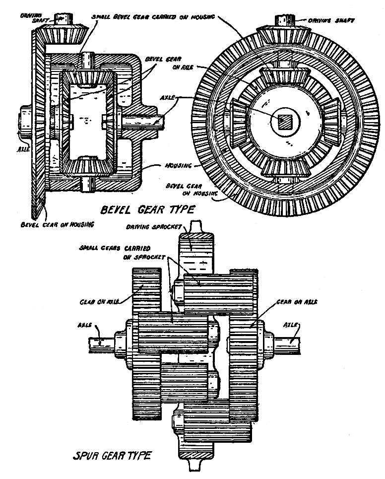
Fig. 43.—Differentials.
In applying a simple form of differential the axle is divided into two parts, to the inner ends of which are fitted bevel gears, these being held at a fixed distance apart by the construction of the housing (Fig. 43). Between the bevel gears and in mesh with both of them are small bevel gears, or pinions, which may revolve [Pg 155]on short studs carried on a ring so that they are a fixed distance apart. When the ring is revolved it carries with it the studs and pinions. The ring forms a housing that incloses the differential, and is driven by the single chain or driving shaft. To understand the action of the differential, imagine the rear wheels of a car to be jacked up clear of the ground so that they are free to revolve, and the housing to be revolved by hand. As it turns, the driving wheels will turn also, for the resistance to each is the same, and the pinions, being in mesh with both bevel gears, cannot revolve on their studs. If one of the wheels is now held stationary and the housing revolved, the bevel pinions will revolve on their studs, and roll around on the stationary gear; this will drive the gear of the free wheel at twice the speed of the housing. The revolving of the housing in the first instance caused the wheels to turn equally at the speed of the ring, and in the second permitted one to remain stationary while the other turned at twice the speed of the housing, the speed of the latter being unchanged. The first is the effect when the car moves straight ahead, and[Pg 156] the second the result if the car could make so short a turn that it would pivot on one wheel.
With the wheels jacked up, hold one hand lightly against one of the wheels, so that while it may turn, there is more resistance to it than to the other. If the housing is now revolved, the bevel pinions will revolve on their studs, and roll slowly around the gear of the wheel that presents the resistance, the free wheel being revolved at a higher speed than the housing. This is the condition when the car takes a corner, for there is then more resistance to the inside than to the outside wheel, and it slows down; this will start the pinions revolving on their studs, and they will drive the outside wheel correspondingly faster.
With the housing revolving at a fixed speed, the outside wheel will revolve as much faster as the inner wheel is revolving slower; for an illustration, if the housing makes fifty revolutions a minute, and the inner wheel is slowed to forty, the outer will be driven at sixty revolutions.
If one wheel of a jacked-up car is revolved by hand, the other wheel will revolve in the[Pg 157] opposite direction. This is caused by the housing remaining stationary and the pinions being revolved on their studs by the turning of the wheel, the movement being transmitted to the free bevel gear and wheel in the reverse direction.
The bevel gear differential described was the early type, but a more recent design employs spur gears. The axle ends carry spur instead of bevel gears, these being in mesh with other spur gears that are long, but of small diameter. These small gears are in pairs, as shown in Fig. 43, being in mesh with each other at their inner ends, and each member of a pair meshing with one of the axle gears. The small gears revolve on studs supported by the housing that is revolved by the drive, the studs in this case being parallel with the axle instead of at right angles to it, as are the studs in the bevel-gear type.
If the small gears meshed only with the axle gears, and not with each other, revolving the housing would cause them to roll around the axle gears, all rotating on their studs in the same direction, and the axle gears remaining[Pg 158] stationary. Being in mesh with each other, they cannot revolve in the same direction, for when two gears are in mesh they must revolve in opposite directions. Thus the small gears cannot roll around on the axle gears when the housing is revolved, and if there is equal resistance to the turning of the wheels, the small gears will not revolve on their studs, but will carry the axle gears with them.
If the car is turning a corner, the greater resistance to the inner wheel will cause the small gears to revolve on their studs, rolling around the resisting gear and driving the other correspondingly faster.
On cars with double-chain drive, the differential is fitted to the jack shaft, and of course receives the drive from the change-speed mechanism through its housing.
Both the driving-shaft and double-chain drive have points of advantage and of weakness, and each type has its advocates. For the double chain, great strength can be claimed with light weight, as the axle is in one piece, and perfectly adapted to support the car. Against it is the difficulty of keeping the chains[Pg 159] properly lubricated, and their consequent wear and stretching. The driving-shaft type has the advantage of the perfect lubrication of the parts, for all may be inclosed and running in oil or grease; the rear axle must be divided, however, which requires it to be heavily braced in order that the weight imposed on it may not bend or spring it out of line. Where a bent dead axle can be straightened by a blacksmith, a similar condition in a live axle requires the services of an expert mechanic; on the other hand, bevel gears make less noise than chains.
Even when on the direct drive, the crank shaft makes more revolutions than the rear wheels, in order that the momentum of the moving parts of the engine may be sufficient to keep the car in motion. On shaft-driven cars, the bevel on the driving shaft has fewer teeth than that on the axle, so that it revolves more than once to one revolution of the axle. On chain-driven cars, the driving sprockets are smaller than those driven. This driving-gear ratio,[Pg 160] as it is called, varies from one and a half to three and a half, or, in other words, the wheels revolve once while the driving shaft or sprocket makes from one and a half to three and a half revolutions. Other conditions remaining equal, a higher driving gear gives the car lower speed, but greater ability in hill-climbing and the traversing of heavy roads.
[Pg 161]
The steering of a motor car, or the change in the direction of its movement, is effected by changing the position of its steering wheels, usually those in front, in relation to the rear wheels. In a horse-drawn vehicle, the axles are parallel when it is moving straight, as are also the planes of its front and rear wheels. To turn the vehicle to one side or the other the front axle is swung so that it is out of parallel with the rear axles, the vehicle turning to the side on which the axles would meet if they were extended. This construction requires the wheels to run loose on the axle, and the axle to be permitted to swing on the pivot by which it is attached to the body of the vehicle.
Such a construction would be impracticable[Pg 162] for an automobile, because the weight resting on the front axle would require the pivot to be of greater strength and stiffness than could be conveniently obtained, and because of the effort that would be necessary to swing the axle in steering. The front axle of an automobile is stationary, and the steering effect is obtained by pivoting short pieces to its ends, these carrying the wheels. From these pivoted ends, called knuckles, extend short steering arms, which are connected by a drag link, so that moving the drag link moves the pivoted ends of the axle and the wheels to correspond (Fig. 44).
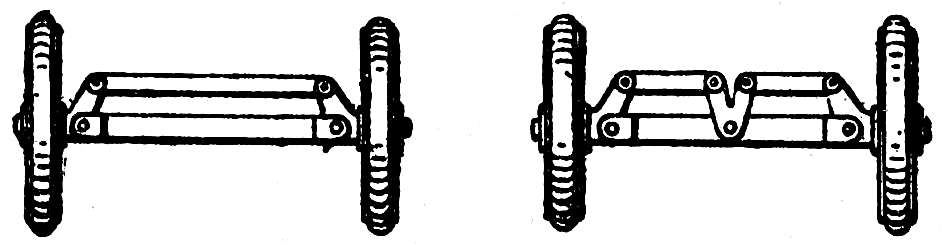
Fig. 44.—Two Arrangements of the Drag Link.
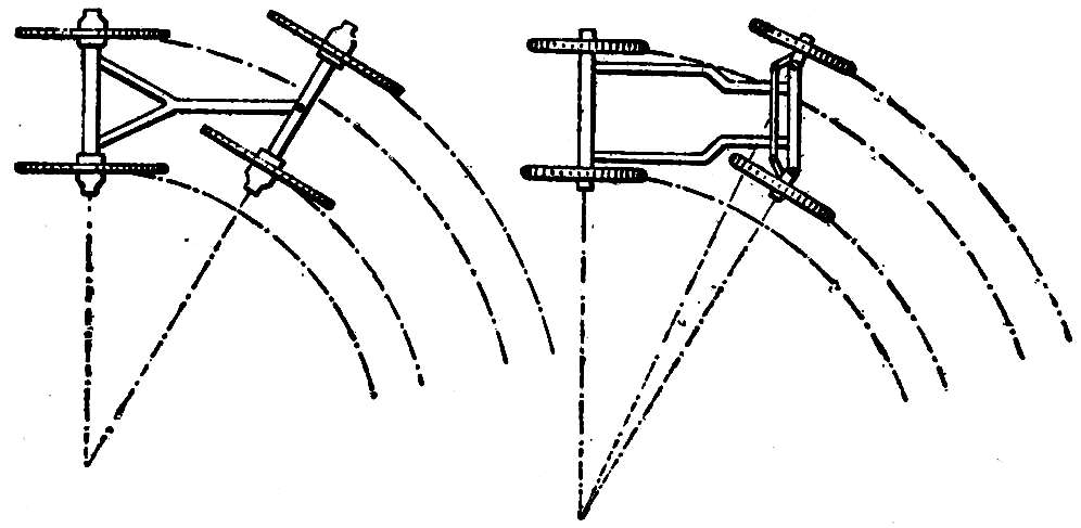
Fig. 45.—Steering Principles.
For a wheel to follow a curved path without slipping, it must be at all times tangent to the path, and will be perpendicular to a radius of the curve at that point. The front axle of a horse-drawn vehicle points toward the center of the circle on which the vehicle may be turning[Pg 163] and forms part of the radius, the wheels, of course, being perpendicular to it (Fig. 45). As the main part of the front axle of an automobile is stationary, only its pivoted ends may point to the center of the circle, and this must occur in order that the wheels may be tangent to the curve (Fig. 45). Both axle ends point to the center, but along different radii; if both pointed along the same radius, it would necessitate their being in line with the stationary part of the axle, which then also would be part of the radius. As the axle ends are in line with different radii of the same curve, it follows that the wheels are perpendicular to different radii, and not parallel with each other, a condition impossible in horse-drawn[Pg 164] vehicles. The front wheels of an automobile are parallel with each other when the axle ends are in line with the stationary part, but go out of parallel as soon as they are at an angle with it, as is the case when the car takes a curve.
If the steering arms projected from the knuckles at right angles to the axle ends on which the wheels revolve, moving the drag link would move each knuckle through an equal angle, and the wheels would be parallel at all times; this is prevented by so constructing the knuckles that the steering arms incline toward each other, with the result that when the drag link is moved, one of the wheels swings through a greater angle than the other, the difference between the angle of each steering arm and the stationary part of the axle increasing with a greater movement of the drag link.
The control of the drag link is obtained either by a steering lever or wheel. When the steering lever is moved by the driver, the drag link is moved to correspond by a connecting rod, and this type is usual in small cars. It is impracticable for heavy cars because it is reversible;[Pg 165] that is, the moving of the steering wheels moves the lever, and a firm grasp is required to prevent the shock of striking a stone or rut from tearing the lever from the hand and changing the course of the car. The irreversible type is used for all but the lightest cars, and while it permits the driver to change the direction of the front wheels it prevents any movement from being transmitted from the wheels to the steering wheel or lever. The screw-and-nut type of irreversible steering mechanism (Fig. 46, B) consists of a[Pg 166] heavy screw attached to the lower end of the shaft that revolves when the driver turns the steering wheel. The screw passes through a nut that is held in guides so that it cannot revolve, and is therefore moved up or down when the screw is turned by the steering wheel. From the nut extends an arm that is connected to the drag link, so that its movement is transmitted to the wheels. The turning of the steering wheel thus moves the nut and the front wheels, but a movement of the front wheels from any other cause is prevented, because no pressure on the nut can revolve the screw. Another type is the worm-and-worm wheel, or worm-and-segment (Fig. 46, A), which, while of different construction, depends on the same principle that the movement of the worm or screw can move a worm wheel or nut in mesh with it, but the movement cannot be reversed.
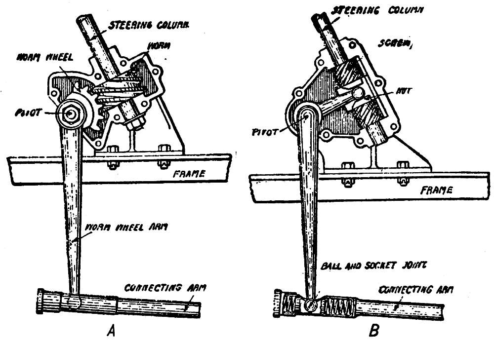
Fig. 46.—Steering Mechanisms. A, Worm and worm-wheel steering gear; B, nut and screw steering gear.
The stationary part of the front axle of an automobile is usually a forging, and must be of considerable strength in order to support the weight imposed upon it by the engine. It is usually bent down in the center, in order that it may be the lowest point of the mechanism,[Pg 167] thus to receive possible blows of stones or other high points of the road that would cause serious damage should they strike the crank case or fly wheel.
The brakes used in controlling the speed of an automobile may be as many as four in number, and there should be at least two, for on them depends the safety of the car. Brakes are of two types, expanding and contracting, and usually operate through the friction between a drum and a band that surrounds it, or blocks that press against its inner surface. The band or contracting brake may be either single- or double-acting, the latter being by far the better. In a single-acting band brake (Fig. 47) a flexible steel band surrounds the drum, one end being made fast to the frame of the car or some other stationary part, and pressure applied by drawing the free end. The friction caused by the binding of the leather or fiber lining of the band on the drum restrains the movement if the drum is revolving in the opposite direction to the pull, but there is little[Pg 168] effect if the revolution is in the same direction as the pull. In the double-acting type, both ends of the band are pulled, and the drum is prevented from revolving in either direction. The single-acting type would be satisfactory when the car moves forward, but will not hold it from running downhill backward, while the double-acting brake holds it in either direction. The expanding brake usually consists of two bronze shoes, of such shape that they fit the[Pg 169] interior surface of the drum. The shoes are pivoted together at one end, and so arranged that the pull of the brake pedal or lever expands them, binding them against the drum (Fig. 47). When pressure is not being exerted, a coil spring, not shown in the diagram, holds them together and out of contact with the drum.
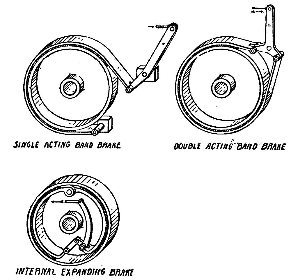
Fig. 47.—Three Varieties of Brakes.
Brake drums are usually attached to the spokes of the rear wheels, and one drum often serves for both an expanding and a contracting brake. Brake drums are also applied to the jack shaft, or to an extension of the countershaft of the change-speed mechanism. It is usual to have one set of brakes controlled by a foot pedal, and another, called the emergency brake, by a lever at the side of the car. The foot brake, or running brake, is always connected to the clutch, so that applying it throws out the clutch. The emergency brake is also connected in the same manner in some makes of automobiles, but this is not recommended, for if it is necessary to stop the car when going uphill, the brakes must be released before the clutch can be thrown in, and the possibility of the car starting downhill backward before power[Pg 170] can be applied, the chance of stalling the engine through this, and the danger of the combination to any but an experienced driver, make it advisable to have the emergency brake separate from any connection with the clutch.
Band brakes are usually lined with leather, to increase the friction between the band and the drum, and this often gives rise to troubles in the burning of the leather when the brake is applied for a considerable period, as in the descent of a long hill. The emergency brake has advantages in that it operates through the friction of metal against metal, but excessive heat from continued application may be enough to melt the metal and fuse together the shoe and drum. For long descents, it is well to use the motor as a brake, for it is logical to consider that the means of propulsion may also be the means of retarding, as the wind that urges a sailboat forward may also bring it to a stop. It is obviously impossible to reverse the motor or gears, but by switching off the ignition circuit and throttling down, the forward movement of the car is caused to operate the motor, and the work necessary in driving the motor as an air[Pg 171] compressor is sufficient to check the speed. The effect is so great that if the low-speed gears are engaged, the car will be brought to a stop even on a steep hill. Another advantage of this course is that it gives the motor an opportunity to cool, which is often necessary after a long ascent.
In case of the failure of the brakes to operate, which may result from poor adjustment or worn bands and shoes, the speed may be checked by throwing out the clutch, switching off the ignition, engaging the intermediate speed gears, and letting in the clutch very slowly. Great care must be taken that the clutch is not permitted to bind suddenly, for that would probably result in the stripping of the gears. If the low-speed gears are engaged, the checking would be so sudden, no matter how slowly the clutch might be engaged, that the shock would probably throw the passengers from their seats.
The failure of the brakes when descending a hill produces a condition that requires skill and coolness, and danger can only be averted by a steady hand and a clear head.
Brakes applied to the rear wheels must have an equal grip on each, for if one binds more[Pg 172] tightly than the other, the car will have a tendency to skid, or slide sideways. In the best cars this is taken care of by an equalizer, in which the pull of the lever or pedal is not applied directly to the brakes, but to the center of a bar, each end of which is connected to one of the bands or shoes. The lever action of this bar distributes the pull equally between the two brakes, and unless there is a great difference in the grip on the two drums, as might be the case if one were oily and the other dry, the effect will be the same on both sides.
For low speeds, solid tires give good results in traction and the absorption of jolts from small obstacles, but for anything above six or eight miles an hour, pneumatic tires are a necessity in preventing the rapid shaking to pieces of the mechanism. A hard tire touches the ground at but one point, and its grip on the road will be much less than that of a pneumatic tire which, being slightly flattened by the weight it bears, presents an oval or elliptical surface to the road. While a pebble will force a solid[Pg 173] tire to roll over it, it will sink into a pneumatic tire, and the jolt that it might cause will be entirely absorbed. Pneumatic tires are formed of alternate layers of heavy canvaslike fabric and soft rubber, and the processes through which they are put in manufacture are supposed to effect their perfect combination; but as it is not the nature of rubber to be absorbed by the fabric, the layers are only bound together by its tenacity. The bending of the sides of the tire under the weight of the car tends to separate these layers, and water or dirt entering between them through cuts quickly brings ruin; it is obvious that the less the sides bend, the smaller will be the opportunity for the layers to work apart. A pneumatic tire should always be pumped as hard as possible, so that it stands up practically round under a loaded car. While the car will ride a little harder under these conditions than when the tires are soft, there will be greater resistance to punctures, and the life of the tires will be increased. The normal wear to a tire should give it a smooth surface, but if it is noticed that the tread is rough and uneven, it may be taken for granted that the[Pg 174] wheels do not run true. Rear wheels will be thrown out of true by the springing or bending of the axle, and front wheels also from this cause, but more probably from faulty adjustment of the steering mechanism or the bending of the drag link or steering arms.
The grip of the tire on the road is much affected by the nature of the surface, the traction on dry macadam being much greater than on wet asphalt. When the pull of the engine on the wheel exceeds the grip of the tire on the road, there will be a slip, and the wheel will revolve without moving the car. This will wear the tread of the tire far more rapidly than will ordinary running. The better the traction of the tires on the road surface, the less will be the tendency of the car to skid or slide sideways, and less power will be lost through the slipping of the wheels. To reduce the chance of slipping, because of wet asphalt or muddy roads, various devices are in use, all of which encircle the tread of the tire, and present a rough surface. The form in most general use consists of chains that fit across the tread, these being detachable and used only in case of necessity. While it is[Pg 175] often done, it is nevertheless bad practice to apply chains or other antiskid devices to only one of the rear wheels instead of to both, for it increases the diameter of the wheel and makes a difference in the resistance against the wheel, causing the differential to operate at all times. The differential is not constructed to operate steadily, and will wear rapidly if forced to do so.
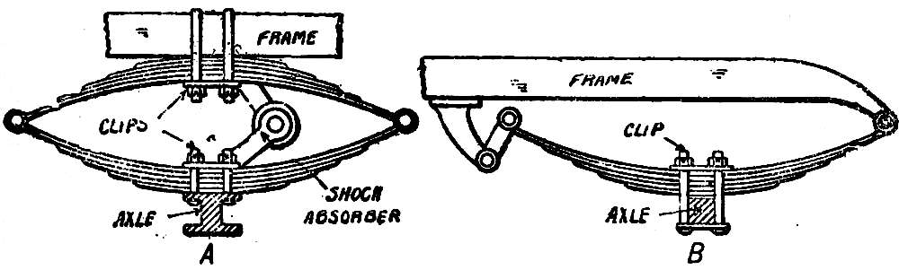
Fig. 48.—A, Full elliptic spring; B, half elliptic spring.
In addition to tires, an automobile is fitted with springs, which are necessary to absorb the shocks and jolts that are too great to be taken up by the tires. These are usually full or half elliptic (Fig. 48), and made of flat plates, or leaves, of different lengths, the small being placed on the large, and all bound together at[Pg 176] the center. The combined action of the springs and tires permits the frame and body of the car to move in a nearly straight line, while the wheels and axles follow the inequalities of the road. When springs break, as is frequently the case, it is from the rebound of the body that results when the wheels drop into a deep hole, the upward movement separating the leaves, and the entire strain coming on the long leaves alone. To prevent this, shock absorbers are recommended, which permit the springs to have a certain amount of action, but check them if they tend to expand or compress to too great an extent. They act either by the friction between metal plates and washers, or by air or oil in a cylinder that permits a piston to move freely to a certain degree, but presents resistance to a greater motion. Shock absorbers are placed between the axles and frame, and there should be four, two to each axle.
As the springs are placed between the axles and body and are flexible, it is necessary to[Pg 177] provide some method of preventing an obstruction in the road from twisting the axle, as might result if one wheel struck heavy sand or a stone while its mate was on good surface. A twist of this sort would throw the axle out[Pg 178] of line with the drive and bind the chain or driving shaft.
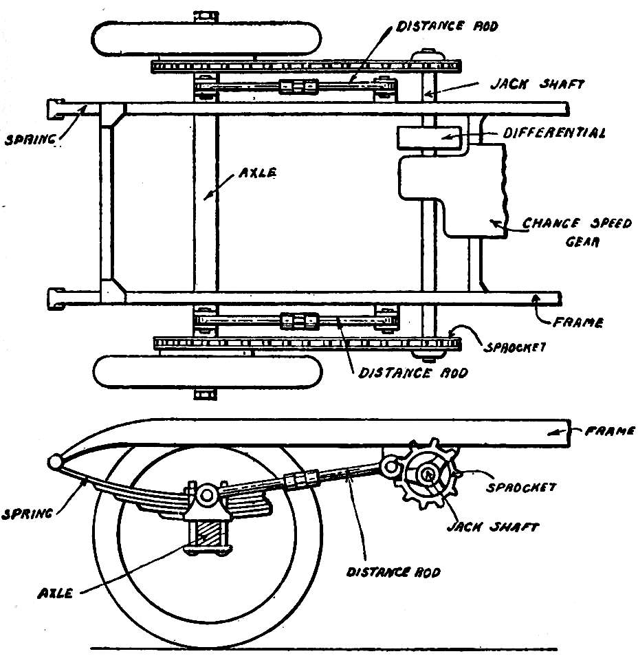
Fig. 49.—Distance or Radius Rods.
To prevent this, radius or distance rods are attached to the axle, one on each side, extending to a point well forward on the frame (Fig. 49). These rods are pivoted to the frame, and have a loose joint on the axle, so that the latter is free to move up and down, but prevented from moving forward or back. Distance rods are adjustable, and on chain-driven cars serve to adjust the chains, which are tightened by lengthening the rods and slackened by shortening them.
[Pg 179]
Practice and experience are the best instructors in keeping the car running, and the operator quickly acquires the ability to recognize the source of trouble from the action of the engine in failing to deliver power, or from the manner in which it stops. Each part of the mechanism may be counted on to give trouble, and the possibilities are numerous, but in general it may be said that an interference with the proper operation of the engine may be laid to the failure of the ignition system or gasoline supply, a defect of the combustion space in not retaining the pressure, or the overheating of the engine.
The ignition system is the greatest producer of trouble, and the reason is usually difficult[Pg 180] to locate. Any interference with the flow of the current, or leaks by which it evades passing over the entire circuit, will cause irregular running or the stopping of the engine, and the circuit must be maintained in the best possible condition in order to prevent these as much as possible. The wires should be well insulated, the insulation of the secondary circuit being heavier than that of the primary because of the higher pressure of the current that must be retained. The constant vibration to which the wires are subjected requires the use of cable composed of a number of strands of fine wire rather than a single heavy wire, for the latter is much more liable to be broken; but in securing the end of a cable under a nut, great care must be exercised that all of the strands are bound. A single strand is hardly noticeable, but if it comes into contact with uninsulated metal, it will permit the current to leak. In making connections, the best plan is to solder the end of the cable to a copper or brass terminal which holds the strands secure, and gives a firm bearing for the nut. Before making connections the terminals should be scraped bright,[Pg 181] and after running the nuts down firmly, covered with vaseline to prevent corrosion. Corrosion of copper or brass produces a greenish deposit (copper sulphate) which is an insulator, and when it forms between the terminals of the conductor it produces high resistance, cutting down or even preventing the flow of current. A worse effect of corrosion is to bind the nuts on the screws, preventing their removal. A loose connection presents resistance to the flow of current, and the current will flow irregularly, as the vibrations bring the terminals together or separate them. A wire broken at a terminal is easily seen, but when a break occurs inside of the insulation, it is more difficult to detect. When a broken wire is suspected, its circuit may be located by testing, and new wires laid, one length at a time, until the faulty one is replaced. It is poor economy to use cheap wire, for the best is none too good for the hard use to which it is put. The wearing away of insulation by chafing will produce a short circuit, and the wires should be prevented from coming into contact with any part of the car or engine in such a manner as to give this result.
[Pg 182]
When a battery is exhausted, or nearly so, it will not magnetize the core of the coil sufficiently to induce a current that will give a strong enough spark to ignite the mixture. The length of time that a battery should last, or the mileage that it should give, is learned from experience, and when it is exhausted in less time there is evidence that it has either been short-circuited or that the current has been used too extravagantly.
The extra source of current that should be provided should not be switched into circuit until the short circuit that exhausted the regular source has been located and removed, or there will be a further waste of current. It occasionally happens that through carelessness the battery is so connected that one of the cells is reversed, in which case the current will be reduced by the loss of the current from two cells, for the energy of the reversed cell will neutralize that of another. If both sets of battery have become exhausted by short circuit, current for further running may be[Pg 183] obtained by connecting the two sets together in multiple, supposing that each set is, as is usual, connected in series.
An apparently exhausted dry battery will recuperate, or pick up, if allowed to stand, but a storage battery that shows 1.8 volts or less for each cell should be immediately recharged, for further use will cause fatal injury.
The principal troubles that come to magnetos are due to lack of lubrication and the weakening of the permanent magnets. The clearance between the armature and the pole pieces between which it revolves is very small, and even slight wear of the bearings through insufficient lubrication will permit the armature to touch. The oil cups with which the bearings are provided must be kept filled, or if the parts are connected to a mechanical lubricator, the proper adjustment must be maintained.
When a magnet is permitted to stand without a piece of iron connecting the poles, the magnetism will dissipate; to prevent this, a bar of soft iron, called a keeper, is placed across the[Pg 184] poles, the magnetic lines of force flowing through it from one pole to the other, and the strength being retained. The permanent magnets forming the field of a magneto are very strongly magnetized, and the proportion of the strength lost through misuse will be large, resulting in their being weakened to such an extent that the current produced will not be sufficient for ignition purposes. These magnets can be re-magnetized by the makers when this occurs, the magneto regaining its current-producing ability.
The strength of the magnets will be retained for a much longer period if, when the car is standing, the armature is in such a position that it acts as a keeper; this will occur when its iron core is horizontal. As the armature will be in this position when the current is being produced, it is only necessary to bring the engine to a stop at the point when one of the pistons is approaching the end of a compression stroke. On leaving the car, the low speed should be engaged and the clutch withdrawn; the engine may be cranked slowly, and the armature held in position by throwing in[Pg 185] the clutch to hold the crank shaft when compression is nearly complete.
It is most inadvisable to take a magneto to pieces without an exact knowledge of its construction. Except for lubricating the bearings, it is best to leave it entirely alone. In setting a magneto, it must be remembered that it is not delivering current continuously, and that when the iron core of the armature is parallel to the poles of the magnets no current is produced. The greatest strength of current is delivered as the core moves into a vertical position, and revolving the armature by the fingers will show this, for during part of a revolution it will turn easily, and during the rest of the revolution there will be resistance. The engine should be cranked until a piston is near the top of a compression stroke; holding it there, the magneto gear may be meshed with that on the half-time or crank shaft in such a manner that the armature core has moved a trifle past the vertical position. This will result in the production of a current at the instant that it is necessary for the ignition of the charge. (See Appendix.)
[Pg 186]
There is always a small spark between the vibrator contacts of a coil, and in time the platinum will be burned and corroded, the oxide that forms being an insulator and preventing the flow of the current. In such a case the points may be smoothed with a fine flat file and polished on a strip of leather, or if too far gone for this, may be renewed by soldering a short length of platinum wire to the adjusting screw and a plate of the same metal to the blade. While this job is a delicate one, it is not beyond the range of a careful amateur.
When the insulation of the coil or condenser breaks down, as may result from overwork or long use, it should be returned to the maker, for the construction of a coil is exceedingly delicate, and repairs on it require expert workmanship. It is not advisable to take the coil apart in any way, beyond the vibrator parts, for inexperienced handling may injure it beyond repair.
[Pg 187]
The spark plug is a frequent source of trouble, for the insulation may break down, or a carbon deposit may form between the points, either fault permitting the current to pass without jumping the gap. Plugs should be so made that when the parts are screwed together the strain will not come against the insulation. Porcelain insulation is brittle, and may be cracked inside the sleeve, the damage not showing on handling and inspection, but being sufficient to permit the spark to pass inside of the sleeve instead of between the points. Mica insulation is usually formed of a large number of washers squeezed together under great pressure, but the action of the heat and the presence of oil will frequently cause the layers to separate, permitting a short circuit.
The carbon deposit that fouls and short-circuits spark plugs results from a rich mixture, or overlubrication, and this should be prevented by proper adjustments. Under the intense heat the carbon bakes hard, and can be removed only by scraping or by the action[Pg 188] of strong ammonia or gasoline. As in scraping the smooth surface of the insulation may be scratched (which would give a rough surface to which a fresh carbon deposit would cling more tightly), the removal of the deposit by ammonia or gasoline, applied with a stiff brush, is recommended.
The points between which the spark passes should be about one thirty-second of an inch apart. After long use, the corrosion due to the heat of the spark will increase this distance, when the points should be bent together. The high compression through which the spark is required to pass presents greater resistance than air at atmospheric pressure, practically in proportion to the pressure, and a current that will produce a spark outside of the cylinder may not have sufficient pressure to give a like result when the engine is running. If the pressure of the compression is four times that of the atmosphere, the current should be able to produce a spark four thirty-seconds, or one eighth, of an inch long outside of the cylinder, and for safety this should be increased four-fold.
[Pg 189]
The stationary point of the igniter is carried on the end of a screw that passes through the cylinder head or wall, and by means of this screw its position in relation to the moving point may be altered as desired. The distance between the points when they are separated should be about one sixteenth of an inch; more than this will result in the formation of a longer spark between them, and as the passage of the spark through the high resistance of the compressed charge will produce great heat, the igniter points will be burned and corroded more than need be. The adjustment may be made by loosening the lock nut on the stationary point, and running the screw down until the stationary point is in contact with the movable when the latter is acted on by the cam. The lock nut should be run down until it bears lightly against the cylinder and the point then unscrewed, the lock nut being carried with it, until the latter is about one sixteenth of an inch away from the cylinder. This gives a corresponding distance between the igniter points,[Pg 190] and running the lock nut down firmly will secure it.
The tappet spring should be of considerable strength in order to snap the movable point from the stationary when the tappet ceases to act. Too great strength will bring the movable point against the stationary with such force that the platinum plate that it carries will be battered out of place. The principal difficulty that is encountered is the corrosion of these points, the flow of the current being decreased or stopped by the insulating film that covers them. The blow with which the two come together tends to knock this off and to keep the surfaces flat, but when they become badly worn and pitted they must be filed smooth.
The bearing in the cylinder wall in which the movable point rocks is made after the manner of a valve; the opening must be tight in order to prevent the leakage of compression, but sufficiently free to move as the cam acts on the tappet. This joint cannot be lubricated with oil because of the heat, and the two parts must therefore be kept as smooth as possible.[Pg 191] To attain this result they are ground together as engine valves are ground.
The spring that keeps the revolving part of a timer in contact with the stationary part must be of sufficient strength to squeeze out the vaseline with which the timer is packed, as otherwise the grease will form an insulating film between them, preventing the flow of the current. The timer must be securely attached to its shaft, for if it is loose the contacts will be made at the wrong time, and the sparks will not occur in the combustion space at the correct intervals. All of its parts and connections should be as firm as possible. The rods with which the stationary part is connected to the control lever on the steering column should be provided with adjustments by which lost motion due to wear may be taken up. There are usually several joints in these rods, all of which may wear loose, and if there are no means by which they may be kept tight, the lever will move a considerable distance before the timer[Pg 192] will respond. It is often possible to remedy this by placing coil springs in such positions that they take up the lost motion. A timer should be so set on the half-time shaft that the revolving contact is just touching the stationary contact when the piston is at its highest point in the cylinder on the compression stroke, the control lever being in nearly its most retarded position.
As dirt will interfere with the action of a timer, the cover should always be in place and tightly secured.
A secondary distributer will give trouble through loose contacts, dirt, or the splitting of the spark, the effect of the last being the passing of the spark from the revolving part to two or more contact points instead of but one. Particles from the carbon brush in wearing off may stick to the insulating ring between the contacts and form a path, or a strand of wire may project, producing the same result.
[Pg 193]
Loose switch parts will prevent the flow of the current or give a vibrating contact, and should be frequently looked after. If the switch is mounted on metal, as is occasionally the case, a loosening of the parts or the wearing of the insulation will result in a short circuit that is difficult to locate because the good condition of the switch is usually taken for granted.
Commercial gasoline is frequently dirty, carrying particles of matter that will stop the fine passages and openings of the carburetor, or containing water, the presence of which will prevent the proper operation of the engine. Dirt may be removed by the use of a strainer made of fine wire gauze, and water may be separated by filtering the liquid through chamois skin, the gasoline passing through and the water remaining. It is advisable to have a strainer and trap placed in the piping that connects the tank with the carburetor to form the lowest point of the system, the gasoline passing[Pg 194] through it and being cleansed of dirt and water.
The tank of a gravity feed system is always provided with a small hole or vent, usually drilled through the filling cap, through which air may enter to replace the gasoline that is drawn off in the running of the engine. If this hole becomes plugged with dirt, the escape of the gasoline will reduce the pressure in the tank to such an extent that further flow will be prevented, and the engine will stop with all of the symptoms of a lack of gasoline. On opening the tank for the purpose of investigation, the air supply will be renewed, and the engine will again run, to stop slowly as before. Clearing the hole will relieve the condition. This vent may also cause trouble in permitting water to enter and contaminate the gasoline, this being liable to happen when the car is washed.
The pipe by which the gasoline flows from the tank to the carburetor should project slightly above the bottom of the tank, to prevent sediment from being drawn into it.
[Pg 195]
As gasoline rots rubber rapidly, hose should never be used to conduct it, nor should joints be packed with rubber. Copper and brass are attacked by gasoline less than other metals, and should always be used in preference to iron, which is corroded by the liquid. Joints may be made tight by the use of shellac or soap.
Besides the possibility of getting out of adjustment, the greatest trouble with a carburetor comes from the clogging of the passages and openings with dirt. When dirt enters, it clogs the gasoline inlet valve and prevents it from seating properly, the float chamber being flooded as a result. When the level in the float chamber is raised, more than the required amount of gasoline flows out of the spray nozzle, and the mixture that is produced is too rich. This will also result from the bending of the valve stem or the wearing of the seat, either of which will prevent the proper shutting-off of the flow when the correct level in the float is reached.
A flooding float chamber may also be caused[Pg 196] by a float that is out of adjustment on its stem or too heavy. In the course of time the gasoline will cut a hole through the metal of a float and leak in, and leakage will also occur if the soldered joints open, the float then becoming too heavy and not closing the gasoline inlet valve at the correct time. These holes will be too small to permit the gasoline to be poured out, but by placing the float in hot water, the gasoline will be evaporated and driven out as a gas. In repairing a float, as little solder as possible should be used in order that the weight of the float may not be greatly altered. A cork float will become soggy and heavy if the varnish coating is damaged and the gasoline soaks in.
Carburetors are built so that the float valve and spray nozzle may be easily cleaned, for by withdrawing plugs fine wire may be run through them. When a carburetor is taken apart for more thorough cleaning, the position of the gasoline and air adjustments should be remembered, in order that they may be replaced in approximately the correct positions, thus saving time in making the adjustments that will be necessary.
[Pg 197]
The main air intake should be kept clean, especially when it is covered with a wire gauze screen. Dirt will reduce the size of the opening, and the air that enters will not be sufficient to give a mixture of the correct proportion. The screen should be kept clean and free from oil, for the latter is a dust collector.
A leak in the combustion space will reduce the compression by permitting the fresh mixture to escape during the compression stroke, and will also give an escape for the pressure resulting from the combustion, the pressure on the piston being reduced in consequence. The most frequent cause of leakage is worn valves, the intense heat tending to warp the disks and to roughen their surfaces, the exhaust valve being especially liable to this as it is surrounded by the hot gases during the time that it is open. A badly fitting spark plug, igniter stem, relief cock, or other opening into the combustion space will produce the same result. Whenever possible, these parts should be fitted with copper asbestos washers, which are soft enough to[Pg 198] squeeze into the inequalities of the surface, at the same time resisting the heat and pressure.
When piston rings or cylinder walls are cut or scratched by running without oil, the pressure will escape into the crank case, which, while warm when the engine is running properly, will be heated to a very noticeable degree under these circumstances. The only remedy is the use of new piston rings and the reboring of the cylinder. Piston rings, being of cast iron, are brittle, and must be handled carefully. To place them in position in their grooves, thin strips of steel, like pieces of a hack-saw blade, should be bound to the piston, covering all but the lower groove. The ring for this groove can then be slipped on, and when it is in position the steel strips moved upward to expose the upper grooves, one at a time.
Piston rings are usually prevented from revolving around the piston by pins driven into the piston between their ends; if these are not provided, the turning of the rings will bring their ends into line, and the pressure will leak through them. The appearance of the rings[Pg 199] is the best indication as to whether they are permitting leakage; if they are tight, they will be smooth and polished all around, but if there is leakage, they will be streaked with black carbon deposit.
Other losses of compression may be due to a cracked piston, cylinder head or wall, the former being indicated by a hot crank case and the latter by the presence of water in the cylinder and crank case.
The failing of the cooling or lubrication systems will permit the engine to heat, and if continued will produce disastrous results. The radiator of a water-cooled engine should begin to heat shortly after the engine has started, and will rapidly become warm all over, thus showing that the water is circulating properly. A failure of the circulation may be due to a clogged pump or passage, and the cause should be located and removed without delay. Dirt in the water is the most usual cause of the failure of the pump, and also of the stopping of the circulation in the gravity system. A strainer[Pg 200] should be fitted to the filling cap of the radiator to remove bits of wood, leaves, sand, etc. The connections of the water system are frequently made of rubber hose, and this in rotting will free bits of rubber that will prevent the flow. A difficulty occurring at the clamps that attach the hose to the metal pipes is the tearing off of a strip of the rubber lining, which closes the passage after the manner of a valve.
The fan must be kept running correctly, and if belt-driven, the belt must be kept tight and the pulleys free from oil that would permit slipping.
Water that has been heated freezes much more readily than water that has not, and therefore the water system of an automobile must be carefully guarded against low temperatures. A freeze of the water may crack the water jackets or split the radiator, either of which will require the laying up of the car for repairs. The best protection is to draw off the water if there is the slightest danger of freezing, drain cocks being provided at the low points of the system for this purpose. If this is not practicable, a solution of four pounds of calcium[Pg 201] chloride to the gallon of water, mixed hot and allowed to cool, may be used, and it will stand a temperature of 15° F. below zero without freezing.
The flanges or corresponding parts of an air-cooled motor should be kept clean, for dirt will prevent the free radiation of heat.
A lack of lubricating oil, either through the failure of the supply or the clogging of the pipes, will cause the engine to heat and the piston to stick or seize. When the car is new, it is better to supply too much oil than too little, but when the bearings have smoothed down the supply may be reduced. The operation of the engine is the only indication as to whether it is receiving a proper amount of oil, and rather than run the risk of underlubricating the piston rings and cylinder walls, it is better to have enough to produce a faint smoke at the exhaust pipe. This will show that the engine is receiving a little more than is necessary. Too much oil in the cylinder will foul the spark plug, and as this would prevent the passing of the spark, it is to be as much avoided as too little.
[Pg 202]
When the lubricator pipes are clogged, the easiest method of clearing out the obstruction is to force air through them by means of a foot pump.
[Pg 203]
Any interference with the regular running of an automobile is usually due to engine trouble, and the nature of the irregularity or the unfamiliar noise will often give a clew to the experienced driver by which the fault may be located. When the engine shows that something is wrong, it is of little use to guess at the cause, for changing an adjustment without being sure that it is the right thing to do will probably add to the difficulty instead of remove it. The laying out of a system for the location of a fault is not difficult, and its application simplifies matters when trouble is encountered. By following a process of elimination, the condition of the different parts of the mechanism can be learned, and if on test the ignition system proves to be operating correctly, the production of the mixture may[Pg 204] be considered to be guilty until that in turn is shown to be innocent.
An engine equipped with the make-and-break ignition system is always provided with a conducting bar across the top or side of the cylinders, called a bus bar, connected with the source of current, and each igniter is connected to it through a switch. If one of the cylinders fires regularly, it is an indication that the current is being generated properly, and that no time need be wasted in examining the generator. By means of the switches, the igniters may be tested individually by cranking the engine with one switch closed and the others open. When the clutch is disengaged the engine should run on one cylinder, and if this is the case, the igniter on the line of the closed switch is shown to be in good condition. The opening of this switch and the closing of the next will give a comparison when the engine is again cranked, and if explosions occur, the igniter points may be adjusted until the two cylinders work equally well. If the cylinder does not operate,[Pg 205] the stationary igniter point should be withdrawn and its contact examined; this should be bright and clean. The movable point should be worked by hand, to determine whether the joint is stuck or the spring weak or broken.
If none of the cylinders show signs of explosions, the connections should be examined to make sure that they are secure. On systems employing a magneto alone, the wiring consists of a single wire from the magneto to the bus bar, and the shorter wires from there to the igniters. These wires are clearly visible, and any loose connections or broken wires may be detected without difficulty. If the connections and wiring are in good condition, the fault may be located in the magneto, or, if it has recently been dismounted, its incorrect setting in relation to the crank shaft. (See Appendix.)
If the ignition system proves to be in proper working order, attention may be paid to the carburetor and its connections.
In testing an engine fitted with the jump-spark ignition system, the circuit should be[Pg 206] closed and the crank shaft revolved twice, attention being paid to the sound of the vibrators. On a four-cylinder engine, the timer makes four contacts in two revolutions of the crank shaft, and if all of the vibrators are heard it is proof that the primary circuit is in good condition, and not the seat of the trouble. If only one of the vibrators buzzes, the battery circuit may be considered to be working properly, for otherwise no current could have passed to the coil box. The trouble may then be identified as being in part if not altogether in the adjustment of the vibrators of the dead coils, their connections with the timer, or in the timer itself. One end of a short piece of wire should be touched to the timer binding post of one of the dead coils, and the other to any metal part of the engine, the lubricator, for instance, to form a short circuit through the primary circuit with the exception of the timer and its connections. If the vibrator buzzes, the trouble is not in the coil, but in that part of the circuit cut out by the short-circuiting wire. The same piece of wire may be used to bridge across to any metal part of the engine from the[Pg 207] binding post on the timer at which the wire from the coil is connected, and if the wire from the coil to the timer is in good condition, the vibrator will again buzz, showing that the fault must be in the timer, for all other parts of the primary circuit of that particular coil have been proven to be working correctly. A dirty or faulty contact in the timer, or a loose connection, will probably be the cause.
If the primary circuit is shown to be in good order, attention may at once be given to the gasoline feed, for while the secondary circuits have not been tested, it is extremely unlikely that the spark plugs or their connections will prove defective on all four cylinders at the same time.
Touching the primer of the carburetor will show whether the gasoline flows to the float chamber, for if it is present it will spurt out of the opening through which the priming stem passes. If the air inlet is so arranged as to permit it, gasoline dropping out of it when the carburetor is primed excessively indicates that the[Pg 208] liquid flows out of the spray nozzle, this part thus being shown to be clear. If no gasoline shows around the priming stem, the feed pipe or float valve may be suspected of being clogged, it being taken for granted that there is gasoline in the tank and that the supply cock is open. If it is found that gasoline is present in the air inlet, and that the carburetor is damp with it when the primer has not been touched, it indicates that the float chamber is flooded; the carburetor should be taken apart for inspection and thorough cleaning.
When the engine will not start on cranking it eight times or so, it is useless to continue to crank it, for there is every reason to believe that something is wrong. Too often the difficulty is in forgetting to switch on the ignition circuit or to open the gasoline feed. Cranking the engine slowly will not reduce the pressure in the inlet pipe sufficiently to draw out of the spray nozzle the quantity of gasoline required to form an inflammable mixture; quick cranking is necessary. Too much priming will result[Pg 209] in the formation of a rich mixture; the gasoline should be permitted to evaporate, or the carburetor drained, and then primed gently.
The failure of an engine to start on a cold day may be due to the slowness with which gasoline evaporates when chilled. As it is obviously most unwise to heat the carburetor with a flame, the best thing to do in such a case is to pack it with cloths soaked with hot water. A little gasoline squirted into the air inlet, or cotton waste soaked with gasoline and held over the same opening, will almost always permit the engine to be started; another method is to squirt a few drops of gasoline into the cylinders through the relief cocks.
Regularly occurring explosions indicate that the cylinders are receiving the proper quantity of mixture, and that the ignition is operating correctly. If under these conditions the engine fails to deliver full power, which is shown by the sluggish running of the car, the trouble may be identified as the result of a condition by which power is absorbed between the engine and[Pg 210] wheels. This may be from a slipping clutch, binding brakes, or tight bearings, these more probably on the wheels than on the change-speed mechanism or drive.
The brake rods may get out of adjustment, or the spring stick, with the result that the bands or shoes are in continual contact with the drums. A simple test for the condition of the brakes is to push the car across the floor by hand; it is not difficult to recognize unusual stiffness. This test also applies to the wheel bearings. Engine or transmission bearings that are too tight will heat, and a touch of the hand will show the presence of this condition. A tight bearing should be permitted to cool before readjusting it and proceeding.
Regular but weak explosions may be due to too rich or too poor a mixture, or to the escape of compression. Cranking the engine twice will produce a compression stroke in each of the four cylinders, and if there is a leak, the ease with which the piston in which it occurs may be pulled over dead center will show its[Pg 211] presence. A little soapy water around the spark plug, relief cock, or other opening into the combustion space will show the escape of compression in the formation of bubbles. A hiss inside of the cylinder indicates a leaky piston ring, or that the openings of the rings are in line, and when this sound is sharp and clear, the presence of a broken ring. An additional proof of this is the undue heating of the crank case. If the compression is correct, the carburetor may be readjusted to improve the quality of the mixture. A poor mixture may be due to the partial clogging of the spray nozzle or its passages, and a rich mixture to the choking of the air inlet by dirt or dust, this being especially liable to occur when the part is oily.
The missing of explosions is a common failing of automobile engines, and while it may be due to a variety of causes, the most usual is that the spark does not pass. It is not always an easy matter to determine which of the cylinders is missing; if the missing is constant, the coolness[Pg 212] of the exhaust pipe of one as compared to the others locates the fault. If the missing is not constant, the difference in temperature will not be noticeable, but the one at fault may be located by holding down all of the vibrators but one. If the cylinder corresponding to the free vibrator runs steadily, its vibrator may be held down and another released, this being continued until the faulty cylinder is located. The condition of the secondary circuit of this cylinder may be ascertained by disconnecting the secondary wire from the plug, and holding it about a half inch away from the plug terminal while the engine is cranked. If no spark passes when the timer makes contact, the trouble is in either the wire or the coil; if a spark shows, it should be of good strength, for a current that will produce a fair spark in the open may not have sufficient strength to produce a like result when under compression. If a good spark shows, the spark plug may be suspected of being fouled and thus short-circuited, of having a breakdown in its insulation, or of there being too great a distance between its points. The threads wear a little each time that a spark plug[Pg 213] is removed from the cylinder, and in order to retain a gas-tight joint it is best not to unscrew the plug unless it is necessary.
If the secondary circuit is proven to be in good condition, attention should be paid to the carburetor, for a poor mixture, or water in the gasoline, will cause the engine to miss. A badly fitting exhaust valve will permit the burned gases to be drawn back into the cylinder, the fresh charge thus being weakened, and as the valve will shift around on its seat, this may happen irregularly. Missing will also be caused by a weak or broken inlet-valve spring, or by the sticking of the inlet valve, these conditions resulting in failure to retain the mixture in the combustion space during the compression stroke. This pushing back into the inlet pipe of the charge will usually produce a popping or gurgling noise that is easily recognized.
If an engine runs well at low speed, but misses when speeded up, the trouble may be due to weak battery, stuck vibrator blade, or loose connections. A battery that will produce a[Pg 214] good spark at low engine speed may not be able to respond to the greatly increased demands of high speed, and similarly, at low speed the period during which the timer holds the circuit closed is longer than at high speed, and the vibrator has more time to get into action before the circuit is broken. A loose connection may be so shaken by the vibrations of high speed as to break the circuit.
If the battery is nearly exhausted, it will recuperate during a rest to such an extent that it will produce good sparks, but as its condition of strength is only temporary, the engine will slow down and come to a stop as the current fails. This action of the engine may also be due to carburetor defects by which the vibrations of running either cause the flooding of the float chamber or the clogging of the spray nozzle, the mixture in both cases becoming noninflammable; the condition will also result from an air-bound supply tank.
[Pg 215]
It sometimes happens that the engine will continue to run after the ignition circuit is opened. This may be due to a failure of the water circulation, which is indicated by the low temperature of the radiator, or by the low speed or stopping of the fan from a slipping or broken belt. If the cooling system is working properly, the lubrication must be investigated. If the oil is flowing as it should, the cause will be found in the formation of a carbon deposit in the combustion space, fine points of which will become incandescent and ignite the mixture as it passes into the cylinder or as it is compressed. A more unlikely fault may be that the points of the spark plug are fine enough to become heated in a similar manner; modern plugs are made with points of such size that this possibility need hardly be considered. This ignition of the mixture by other cause than the proper spark is termed preignition.
[Pg 216]
If the engine stops suddenly, the fault will be found in the accidental opening of the switch, or the breaking of a wire or connection. An abrupt stop cannot be caused by anything but an interruption of the ignition circuit, for the cessation of the gasoline feed will bring the engine to a stop slowly, the gasoline in the float chamber and spray nozzle being sufficient to permit weakened explosions before the supply entirely fails. A slow stopping of the engine from causes other than those previously mentioned may be laid to defective gasoline feed, the emptying of the tank, the clogging of the supply pipe, float valve, or spray nozzle, or the closing of the supply cock from jolts and vibrations.
If the engine comes to a stop when there appears to be no fault with the explosions, the cooling or lubricating systems may be at fault, resulting in the heating of the cylinder to such an extent that the piston sticks or seizes. Excessive heat is proof of this, the burning or “frying” of excess oil on the outside of the[Pg 217] cylinder being an early warning. A seized piston may be freed by injecting kerosene into the cylinder, and cranking, the cylinder first being given time to cool.
The noises made by the engine when operating properly become so familiar to the careful automobilist that any other sound is recognized more by instinct than by attention. Faults will often make themselves known by noises, and these may be broadly classified as pounds or knocks, hisses, squeaks, and rattles. A pound that occurs regularly may be due to a loose connecting rod or wrist-pin bearing, and in this case will be heard once to every two revolutions of the crank shaft. A pound that occurs oftener than this may be set down as a loose crank-shaft bearing, or a loose or cracked fly wheel. If often happens that a fly wheel in this condition will make itself heard, while sufficiently tight to show no sign of the defect on casual inspection.
A hard metallic pound is caused by the combustion of the charge before the completion[Pg 218] of the compression stroke; this condition may result from preignition or from the spark being too far advanced. If the latter is the case, retarding the spark will stop the pounding.
Hisses are due to leaks in the combustion space, as already described.
Squeaks indicate a dry bearing, or a lack of lubrication in one of the moving parts. The bearing may be detected by its heat. A squeak of the leaves of a spring will often be difficult to trace and locate, because of its irregularity.
Rattles indicate that something is loose, and should be located without loss of time. All nuts and bolts should not only be tight, but in addition secured in position by the use of lock nuts or cotter pins.
Backfiring, which is an explosion of the mixture in the inlet pipe or carburetor, may be due to a stuck inlet valve that permits flame to pass and ignite the mixture before it reaches the combustion space, but more probably either to ignition occurring so late that combustion is still occurring when the inlet valve opens, or to preignition.
[Pg 219]
Explosions in the exhaust pipe or muffler are due to the presence of unburned mixture, which is passed out of the exhaust valve after ignition has failed, and ignited by the heat of the exhaust pipe, or by the hot gases from the next explosion.
[Pg 220]
In order that an automobile may be maintained at its highest efficiency, a constant watch must be kept over all of its parts, and repairs and replacements made as soon as the necessity is apparent. A worn bearing or loose part may continue to operate, but the wear will be far greater than would occur under normal conditions, and may result in serious breakage. A system of inspection to be gone through every time that the car is used will keep the driver informed as to its condition, and it is best to form the habit of doing this at the end of a run rather than before, for then the necessity for making readjustments or repairs will be fresh on the mind.
The condition of the ignition circuit and of the compression will be shown in revolving the[Pg 221] crank shaft twice, and the action of the carburetor may be ascertained at the same time. Pushing the car across the floor will show the presence of tight brakes or wheel bearings, and the tires may then be examined for cuts. Beginning at the front of the car, every bearing not fed by the lubricator should be oiled, and all grease cups given a slight turn, those that are empty or nearly so being filled. While this is being done, a watch may be kept for nuts and bolts that may have been loosened by the vibrations.
The car should be washed with clear, cold water only, and mud floated off; to remove mud by rubbing or any other method than sluicing it away by the action of a gentle stream of water will scratch the varnish and ruin the appearance of the car. When clean, the varnished parts may be dried with chamois or wash leather, and the finish retained by a light coating of a good furniture polish, which is to be immediately dried by rubbing.
The tires may be cleaned by sponging, but[Pg 222] water should not be allowed to settle in the bead. On cars having the gravity system of gasoline feed, the water should not be permitted to splash on the tank, for it will enter through the vent. Water should also be kept from the upholstery, for if it enters the folds and buttonholes it will cause rotting.
Light and heat are the worst enemies of rubber; spare tires should be kept in a cool, dark place, and protected from dust and moisture. French chalk, or some similar preparation, should be well dusted over the shoes and tubes, and if the tubes are folded, they should occasionally be opened and refolded in fresh places, to prevent the formation of creases. The spare tire that is carried on the car should be kept in a casing, and because a dark surface will absorb more heat than a light, the casing should be tan, gray, or white rather than black. The casing should be as proof as possible against moisture, but for safety should occasionally be removed and aired. The position of the shoe in the holders should be changed every little[Pg 223] while, in order that the straps may not cut into the bead.
The tires on the wheels should receive care, and when the car is left standing, it should be in the shade whenever possible, to protect them from the deleterious action of the sunlight in hardening the rubber. They should frequently be examined, and any cuts filled with strong cement, for otherwise water and sand will work in to form blisters and to separate the layers of fabric from the rubber. The cutting of tires can be reduced by withdrawing the clutch when crossing broken stones, the car coasting over them; driving the car over such a surface will force the tires against the sharp edges, and cutting will result more surely than when the tire rolls over them.
The carbon deposits that will form in the combustion space will in time tend to stick the piston rings in their grooves, and this may be prevented by squirting a few drops of kerosene oil into the cylinders and cranking the engine to distribute it. This should be done at the[Pg 224] end of a run, and the engine permitted to stand in that condition. The first explosions will vaporize the kerosene and drive it off unless too much has been used, when there will be a tendency to foul the spark plugs.
The lubricating oil should be drained out of the crank case every five hundred miles, and the case washed out with kerosene before refilling it with fresh oil. Gasoline has too great a cutting action to warrant its use for this, as it cleans down to the bare metal, while kerosene removes the dirt and grease, leaving a good surface. The case should be filled with oil to such a depth that the connecting rods will dip into it from a half-inch to an inch.
The same should be done with the change-speed gear case every thousand to fifteen hundred miles, for the particles of metal that will be ground from the gears will injure the teeth and bearings. In refilling, the smallest gear should project about an inch into the oil. If the differential is packed in grease, it will run for an entire season with one filling, but if it runs in oil it should be cleaned and washed two or three times a year. The bevel gear case of[Pg 225] a shaft-driven car should receive the same attention.
Properly lubricated chains should run for at least a thousand miles without attention. Because of their exposed position they should be protected against undue wear, and this is best attained by soaking them, when thoroughly cleaned, in melted tallow, working each joint in order that the liquid may penetrate. The chain should be hung up to cool and dry, the surplus tallow being wiped off. The hardened tallow in the joints will prevent grit from working in, and is a lubricant as well. To clean a chain, soak it in kerosene, working each joint to remove the grit. The stretching of the chain may be taken up by lengthening the radius rods, but when the stretching reaches a point that permits it, the chain should be shortened by the removal of a link, and the rods readjusted. If a complete chain is not carried as a spare part, the kit should always include a few extra links for emergency repairs. These are not difficult to apply, being secured in position by[Pg 226] nuts instead of by burring over the ends of the rivets.
To grind a pitted or worn mechanically operated valve, the pressure should be released by compressing the spring and removing the key or other device by which it is held in place. On removing the plug over the valve pocket, the upper surface of the valve disk will be exposed, and it will be found to be provided with a slot. While many grinding pastes may be purchased, good results will be obtained by mixing machine oil with flour of emery until it is thick. Plugging the opening from the valve pocket to the combustion space with cotton waste to prevent the paste from entering the cylinder, spread it on the valve disk and seat, and rotate the disk on its seat with a screwdriver, preferably by means of a bit brace. Every little while the disk should be lifted and replaced on the seat in a new position, in order to distribute the wear evenly, and the grinding continued until a smooth surface shows all around both disk and seat. It is not necessary[Pg 227] to smooth the entire surface of the disk and seat, for the pressure will be retained by a narrower surface.
An automatic valve may be removed from the cylinder by unscrewing or unbolting its cage, and after releasing the spring the cage may be held in a vise while the grinding is performed.
After grinding, all traces of the paste should be removed by washing with gasoline, for any particles that remain will cause rapid wear. When replacing the spring, that of the mechanically operated valve will be found difficult to compress to the point at which the key or washer may be slipped into position, and to simplify this many engines are built with a knob or boss on the cylinder to serve as a fulcrum by which a forked lever may be used. If this is not the case, the spring may be sufficiently compressed in a vise, and bound endwise with wire to retain it, the wire being cut when the spring and key are in position.
A failure of the steering mechanism will cause a wreck more surely and quickly than the breakdown[Pg 228] of any other part of the car, and the best protection is absolute knowledge that it is in perfect condition. All joints should be kept well lubricated, and protected from dust; the leather protectors that are furnished do not accomplish this any too well, but they are much better than nothing, and if the joints are packed with grease before applying them, the results will be good. While guarding against stiffness, there should be very little play or lost motion in the mechanism, and the parts should be frequently examined for bent rods and loose joints. A bend in the drag link or steering knuckles will throw the front wheels out of true, in which case the tires will be badly worn. When going straight ahead, the wheels should be parallel; if this is the case, the angles of the steering arms will give the proper track when making a turn.
The springs of an automobile are in constant motion, and should be as carefully lubricated as the other parts of a car. The spring hangers by which the two halves of a full elliptic spring[Pg 229] are joined, or by which a half elliptic spring is attached to the frame, are often provided with grease cups, but in the absence of these the parts should be frequently oiled. Once a season fresh lubricant should be applied to them. The leaves of a spring may usually be separated enough for this by jacking up the body, applying the jack to the frame; the springs will thus be relieved of the weight, and the leaves will separate sufficiently to permit heavy grease or graphite to be introduced between them by means of a table knife. If the springs are too heavy to permit this, they must be taken apart, which may be done by removing them from the car and releasing the clips by which they are held together. In reassembling a spring, it may be clamped in a vise, when the clip may easily be secured.
In adjusting the vibrators, the best guide is the running of the engine. The musical tone that they make is misleading, for a difference in the steel of which the blades are made, or in the quality of the core, will produce a difference[Pg 230] in the tone, and because two vibrators sound alike is not proof that they are producing equal secondary sparks. With a one-cylinder engine, the adjusting screw may be turned until the engine is running at its best, while at the same time there is the smallest spark between the vibrator contacts. The adjustment of the vibrators of a multicylinder engine is proceeded with along similar lines, all of the blades but one being held down, while the free blade is adjusted until the best results are obtained in the operation of the cylinder to which it corresponds, and the smallness of the spark between the vibrator contacts. When one is correct, it is held down and another released, this process being continued until all are adjusted.
When coil boxes are so built that the units may be removed conveniently, as is usually the case, it often happens that the running of an engine may be improved by matching the coils and cylinders. A difference in the compression in one cylinder will often cause it to run better on one coil than on another, for no two coils[Pg 231] will give identical results. Taking each cylinder in turn, and transposing the coil units in the box, the effect of each coil may be noted, and a combination found that will improve the operation of the engine.
When adjusting a carburetor, it must be remembered that the proportion of liquid gasoline to air in a correct mixture is very small; because this is not well understood, a rich mixture is present far more commonly than a poor one. To begin at the beginning, close both the gasoline and auxiliary air inlets, and opening the gasoline adjustment a very little at a time, crank the engine with the relief cocks open until combustion is secured, the spark being retarded and the throttle nearly closed. When the engine runs, note the color of the flame that shoots out of the relief cocks. A poor mixture will produce a yellow flame, and a rich mixture a red and smoky flame, with black smoke at the exhaust and a smell of gasoline. The flame of a correct mixture is blue and hardly visible. On securing a correct mixture at low speed,[Pg 232] advance the spark and open the throttle to speed up the engine, and the mixture will at once become too rich. Adjusting the auxiliary air inlet by weakening the tension of its spring will bring the mixture to approximately correct proportions. A more careful adjustment under road conditions can be obtained by adjusting the air inlet while the car is being operated, for the position of the carburetor is usually such that this may be done while standing or kneeling on the running board.
Faulty adjustment of the carburetor is often suspected when the real source is in the throttle or governor connections. The bending of a rod connecting the throttle with either the foot, hand, or governor control, or the wear of the joints, will throw the carburetor out, and the possible failure of these parts must be borne in mind accordingly.
In setting or timing the valves of a gasoline engine, the point to be considered is the closing of the exhaust valve, for upon this good results depend. If this valve is held open too long, the[Pg 233] burned gases driven out will be drawn back into the cylinder, and if it closes too soon the greatest possible quantity of burned gases will not have been expelled. The many experiments carried on by the manufacturers, and the attention that they must pay to this point, result in the delivery of cars with valves correctly timed, and usually with marks made on the two-to-one gears to guide in resetting them. In the absence of these guides, the setting of valves need not be difficult, although experimenting is required to secure the best results. The first step is to locate the position of the piston in the cylinder. There is always an opening in the cylinder head—a relief valve, the spark-plug opening, or other—and a stiff wire may be dropped through it, with its lower end resting on the piston and its upper end projecting. As the piston is moved by cranking the engine, the wire will move with it, and is to be marked with a file at its highest and lowest positions. While no fixed rule can be laid down, it may be said that in general the exhaust valve should close when the piston has made from 1/64 to 1/32 inch of its outward stroke. The two-to-one gears having been unmeshed,[Pg 234] the cam shaft may be revolved in its bearings by hand; cranking slowly, move the piston down from its highest point to that at which the exhaust should close, and hold it there. Revolve the cam shaft until the nose of the cam is passing from under the roller of the valve-lifter rod, and the valve just closed. This point may be accurately ascertained by placing a strip of thin paper between the valve-lifter rod and valve stem; when the cam is acting on the valve-lifter rod, the paper will be pinched, but the seating of the valve will release it. When the paper can be pulled out, mesh the two-to-one gears, and the relations thus established between the crank and the cam shafts will be maintained. Cranking the engine a few times, using the strip of paper, will verify results, and the engine may then be started and the effect noted. If the running is not satisfactory, unmesh the gears, and mesh them with a difference of one tooth, first one way and then the other, noting results, and retaining the most satisfactory position. Cams are often cut in one piece with the cam shaft, and the gear keyed on the end; there is therefore no chance[Pg 235] to make a finer adjustment than what is permitted by shifting the gears one tooth at a time. On multicylinder engines, one cam shaft operates all of the exhaust valves, and the setting of one valve sets all.
When inlet valves are of the mechanically operated type, but controlled by a separate cam shaft, this must be set in a similar manner. The nose of the cam should just be coming into contact with the push rod roller at the instant when the exhaust valve is completely closed. This should occur as the piston begins to move outward on the inlet stroke, the exact position being determined by experiment.
When the cams are so badly worn that if they are set to open correctly they close too soon, the best remedy is a set of new cams; for while the brazing of a strip of brass to the sides of the cams can be resorted to, the result is only temporary at best, and not as accurate as that secured by the use of new cams.
While the tension of the spring of an automatic valve is sometimes controlled by a nut, its adjustment usually depends on the stretching of the spring to strengthen it, or the cutting off[Pg 236] of part of a turn to weaken it. The tension should be adjusted, one cylinder at a time, until the best results from each are secured.
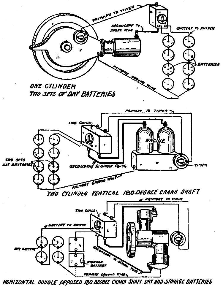
Fig. 50.—Jump Spark Wiring Diagrams.
In laying the wires for the ignition system, only the best wire should be used, and all contacts should be bright and clean. Connections should be tight, and covered with vaseline to prevent corrosion, additional protection being secured by binding all exposed places with so-called electric tape. There should be the fullest protection against chafing and moisture, and no sagging of the wires. Beginning with the battery, the cells should be placed in a box that holds them securely, so that there may be no jolting, for this in working the wires will tend to loosen the connections. In connecting the cells, the wires should be cut to correct length, but not so short that they will be drawn tight when connected. The insulation should be cut off cleanly, and the paraffin that will cling to the metal scraped off. The ground wire may then be run, after which the wires from the two batteries may be connected to the switch. [Pg 238](Fig. 50). On multicylinder engines, one circuit should be completed and tested before another is started, as this obviates the danger of confusing the wires. The primary wire should be run from a coil unit to its timer contact, making sure by the buzzing of the vibrator that the current flows when the switch is closed. A buzz of the vibrator when the timer is not making contact indicates a short circuit. The primary circuit for the coil having been correctly arranged, the secondary connection should be made and tested before laying the primary of the next coil unit. In making the timer contacts of a four-cylinder engine the firing order as established by the opening of the exhaust valves must be kept in mind. With the spark control lever in the retarded position, the timer should be set so that it is just beginning to make a contact when the piston in cylinder No. 1 is at top dead center of the compression stroke. This contact should then be connected to the primary terminal of the first coil, and the secondary of that coil connected to the spark plug. If the firing order is 1, 2, 4, 3, (Fig. 51), cylinder No. 2 will be the next to fire, and the [Pg 240]primary of coil 2 should be connected to the next timer contact in the direction of rotation. As the next cylinder to fire will be No. 4, the timer contact that will next be reached should be connected to coil No. 4, the remaining contact point being connected to coil No. 2. In the diagram the timer is supposed to be moving in the same direction as the hands of a watch.
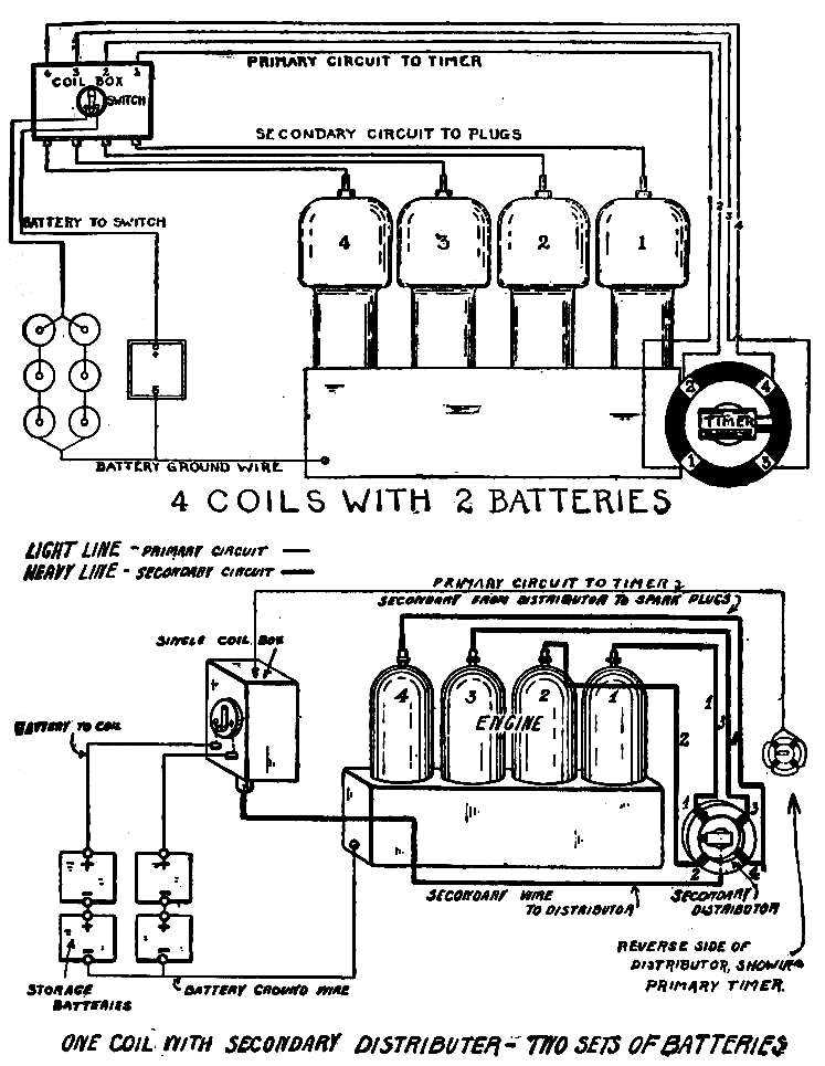
Fig. 51.—Jump Spark Wiring Diagrams.
There is no difference in the wiring of a horizontal double-opposed and a two-cylinder vertical 180° crank-shaft engine, as shown in Fig. 50, except that the timers are so built that in the first the two contacts are a quarter revolution apart, and in the second a half revolution.
In wiring a car with a single coil and secondary distributer the four contacts of the timer all lead to the primary terminal of the coil, the firing order being according to the manner in which the secondary terminals of the distributer are connected to the cylinders (Fig. 51).
Wiring for the make-and-break system is much simpler than that of the jump-spark, and when a magneto alone is used, it consists, as will be seen from Fig. 52, of only a wire from the magneto to the igniters, the other terminal of [Pg 242]the magneto being attached to its metal base in such a manner that the ground connection is made when the magneto is secured in position on the engine. The firing order is according to the setting of the cams that operate the igniter tappets.
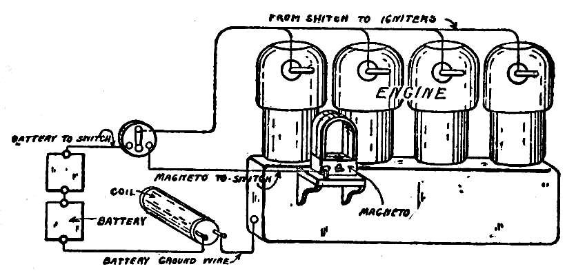
Fig. 52.—Make-and-Break Wiring Diagram. Magneto and coil. Battery for starting.
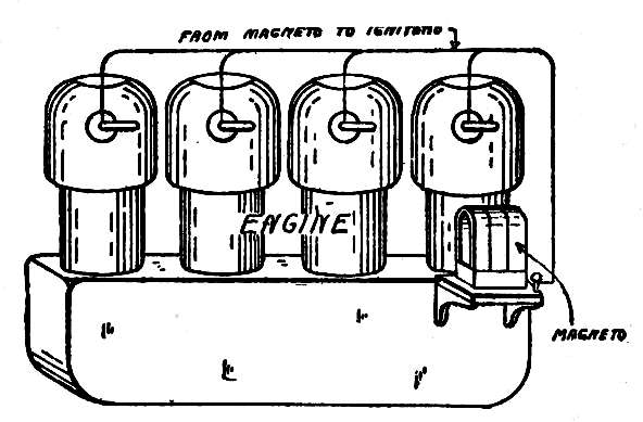
Fig. 53.—Make-and-Break Wiring Diagram. Magneto ignition without coil. Starting on magneto.
[Pg 244]
| PART. | LUBRICANT. | QUANTITY. | |
| Engine cylinder | Cylinder oil | 6-12 drops per minute. | |
| Engine bearings | Cylinder oil | 8 drops per minute. | |
| Require constant attention. | Fan bearings | Cylinder oil | 1 drop every 2 minutes. |
| Magneto, plain bearing | Cylinder oil | Keep pockets ⅔ full. Wash out with kerosene once a season. | |
| Clutch leather | (Vegetable), castor oil, neatsfoot oil | If clutch slips or leather gets hard, keep off machine oil. | |
| Valve lifters | Cylinder oil | With oil-can. | |
| Timer-shaft | Cylinder oil | With oil-can. | |
| Pump shaft drive | Cylinder oil | With oil-can. | |
| Magneto drive | Cylinder oil | With oil-can. | |
| Lubricator shaft | Cylinder oil | With oil-can. | |
| Require attention daily. | Clutch release | Cylinder oil | With oil-can. |
| Lever bearing | Cylinder oil | With oil-can. | |
| Steering knuckle | Grease | One turn. | |
| Water pump | Grease | One turn. | |
| Clutch-shifting collar | Grease | One turn. | |
| Transmission bearings | Grease | Two turns. | |
| Outer bearing live rear axle | Grease or oil | Two turns. | |
| Starting-crank bracket | Cylinder oil | Few drops. | |
| Spring shackles | Cylinder oil | Few drops. | |
| Make and break tappets | Cylinder oil | Few drops. | |
| Pedal-shaft brackets | Cylinder oil | Few drops. | |
| Speed-change lever | Cylinder oil | Few drops. | |
| Emergency lever | Cylinder oil | Few drops. | |
| Require attention weekly. | Brake supports | Cylinder oil | Few drops. |
| Brake equalizers | Cylinder oil | Few drops. | |
| Control levers and joints | Cylinder oil | Few drops. | |
| Spring hangers | Cylinder oil | Few drops. | |
| Clutch; multiple disk, steel on steel | Spindle oil and kerosene, or kerosene and little graphite | ||
| Clutch; multiple disk, leather on steel | No oil, little graphite | ||
| Internal expanding clutch | Thin oil | ||
| Engine crank case. | Cylinder oil. | ||
| Require attention every two weeks or every 300 miles.[Pg 245] | Steering gear case. | Grease. | 3 turns or gunful. |
| Transmission-case, sliding gear system. | Gear case compound or heavy oils, or either mixed with about ten per cent. of graphite. | Let gears dip. | |
| Transmission case, individual clutch type. | Light motor oil and little graphite. | ||
| Planetary transmissions. | Non-fluid oil, or oil and graphite. | Fill up no higher than shaft bearing. | |
| Live rear axle housing. | Non-fluid oil or heavy steam engine cylinder oil; grease and oil. | One quart. | |
| Magneto, ball bearing. | Cylinder oil. | Small amount. | |
| Front and rear wheel-hubs; ball or roller bearing. | Grease. | ||
| Require attention monthly or every 500 miles. | Front and rear wheel-hubs; plain bearing. | Graphite and oil. | |
| Leather boots of steer-rod joints and steer drag-rod joints. | Grease. | ||
| Universal joints. | Grease. | Remove covering, inspect and repack. | |
| Torsion and distance rods. | Oil. | ||
| Timing gears. | Non-fluid oil; graphite if exposed. | ||
| Require attention at greater periods. | Friction disk transmission. | Keep oil off friction surfaces, wash off with gasoline, dress with belt dressing or French chalk. | Renew friction compost every 1,000 miles. |
| Chains. | Chain graphite. | Twice a year boil in graphite and grease after washing well in kerosene. |
[Pg 247]
[Pg 249]
The red-painted toy magnet that is one of the properties of childhood and with which everyone is familiar, may well be used as the beginning of a study of the magneto, for with it the characteristics of magnetism may be observed. A little experimenting will show that the magnet will attract, or “pick up”, iron and steel objects only, having no effect on copper, brass, lead, wood, or, for practical purposes, any other substance. Furthermore, it illustrates the fact that when iron and steel are in contact with it, they in turn become magnetic, able also to attract tacks and other bits of the same metals. Iron, however, is shown by experiment to be magnetic only when in actual contact with the magnet, losing its magnetism as soon as the contact is[Pg 250] broken, while when steel is magnetized by touching it to a magnet it remains magnetic. This fact is illustrated by the magnet itself, which is of steel and therefore capable of retaining its power for a greater or less time, depending on its quality and hardness.
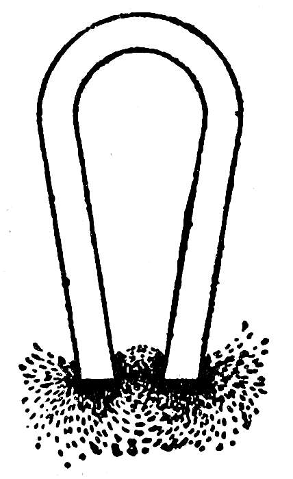
Fig. 1.
Magnetic
Lines of
Force.
If iron filings are scattered on a piece of paper laid over a magnet they will not fall evenly and regularly, but will collect most thickly at the ends, or poles, of the magnet, showing that there the magnetic attraction is stronger than at any other points. If the filings are examined closely it will be seen that they have taken up definite positions, forming lines and curves extending between the two poles (Fig. 1). This is the simplest method by which the magnetism may be made visible, and it illustrates the fact that the power of a magnet acts in a series of lines passing from one pole to the other. If a piece of iron or steel is placed across the poles of a magnet these lines, or as many of them as possible, will use it as a bridge or conductor, because they can pass through it more easily than through air. Such a piece of iron or steel is called a keeper, and by its use the magnet[Pg 251] will retain its strength for a much greater time than if the lines are obliged to make their way through the far greater resistance that the air presents to their passage.
These lines, which are known as magnetic lines of force, always move in the same direction, passing through the air or the keeper from the north pole of the magnet to the south pole, and passing through the metal of the magnet itself from the south pole to the north pole.
The strength of a magnet depends on the number of these lines of magnetic force that it possesses. If two magnets, one strong and the other weak, are placed under sheets of paper on which iron filings are scattered, their comparative strengths are clearly shown by the difference in the number of lines of force that the filings show them to possess.
The space through which a magnet makes itself felt is known as the magnetic field, and this is large or small, according to the number of lines of force. The stronger the magnet, the larger will be the sweep of the curves of its lines of force, and the greater will be the field that they form.
When a piece of iron or steel is placed in contact with a magnet, the lines of force flow into it, and it becomes magnetized, throwing out lines of force[Pg 252] and forming its own magnetic field, which is quite distinct from the magnetic field of the original magnet. If the piece is of iron, its lines of force and its field die away as soon as it is separated from the magnet, but a piece of steel once magnetized will retain its magnetism and, of course, its lines of force.
A wire of nonmagnetic metal, such as copper, for instance, will not have the slightest attraction for iron filings, but when an electric current is passed through it the filings will act as if the copper were a magnet, clinging to it as long as the current passes, and dropping as soon as the circuit is broken. As a matter of fact, an electric current sets up lines of magnetic force exactly similar to those of a permanent magnet, their number being in proportion to the strength of the current.
As has been stated, iron becomes magnetized when magnetic lines of force flow into it. If, therefore, a wire through which an electric current passes is wound around an iron rod, the lines of force set up by the current will pass into the rod and magnetize it, so that it sets up its own magnetic field. This magnetic field is created when the electric current starts flowing in the wire and dies out when the flow of the current is stopped, for then[Pg 253] the lines of force due to the current die out, and the iron, which depends on them for its magnetism and which has not the ability to retain its lines of force, returns to its original nonmagnetic condition. An arrangement of this sort, consisting of a soft iron core, around which is wound a number of layers of insulated wire, forms an electro-magnet, and will produce a magnetic field whenever an electric current passes through the wire. The action is practically instantaneous, the magnetic field appearing and dying out on the making and breaking of the electric circuit.
A magnetic field may thus be produced by the action of an electric current, and an electric current in turn may be produced by the action of a magnetic field. To generate a current by this method it is only necessary to place a conductor forming a closed circuit in a magnetic field, and to change the strength of the field, making it stronger or weaker. For an example, a length of insulated wire may be wound on an iron bar, and the bar then touched with a magnet. As soon as the lines of force flow into the bar it becomes magnetized and sets up a magnetic field in which the lines of force follow the law and flow from one pole to the other through the air. The formation of this field is exceedingly[Pg 254] rapid, but during the time that the field is forming and increasing to its full strength, an electric current will flow in the wire winding. When the field has reached its full strength, the flow of the current ceases. On separating the bar from the magnet it loses its magnetism, and the field set up by it dies away; or in other words, its strength undergoes another change, now growing weaker as the bar returns to a nonmagnetic condition. This dying out of the field generates another momentary flow of current in the wire, which moves in the direction opposite to the flow of the current generated while the strength of the field was increasing.
The current generated is called an induced current, and the method of producing it is called induction.
The intensity of the induced current in any given winding depends on the extent of the change in the strength of the field and upon the rapidity with which it occurs. A bar of iron is limited as to the strength to which it can be magnetized; or in other words, it can only set up a limited number of lines of force. Increasing the strength of the field from nothing to this point, or reducing its strength from this point to nothing, gives the greatest change in strength possible to obtain, and if this change occurs[Pg 255] in the shortest possible time, then the current induced will be of the greatest intensity that can be obtained from a conductor of the size and length used.
For an understanding of the action of a magneto it is necessary to bear in mind the following points:
First. That a magnetic field is composed of lines of magnetic force that flow from one pole of the magnet to the other.
Second. That the lines of force will take the path that presents the least resistance.
Third. That an electric current will be generated, or induced, in a conductor placed in a magnetic field whenever the strength of the field changes.
Fourth. That the current flows only while the change in strength is taking place, ceasing to exist when the field becomes uniformly strong or weak.
To make a practical application of the laws governing the production of an induced current, a conductor forming a closed circuit is placed in a magnetic field, and the strength of the field caused to change, alternately becoming strong and weak. In magnetos, the magnetic field is due to two or more powerful steel magnets, and the conductor, a length of insulated copper wire, is wound on a soft iron core and revolved between the poles of the magnets[Pg 256] where the field is strongest. The magnets are known as the field of the magneto, and the wire on its core the armature. The shape of the iron armature core is shown in Fig. 2, the winding being indicated by heavy black lines. On the inside of the poles of the field are pole pieces, which are blocks of soft iron hollowed out to receive the armature. As the successful operation of the magneto requires the lines of force to have as easy a path as possible, the air space between the armature heads and pole pieces is very small, being in the neighborhood of 1/100 of an inch.
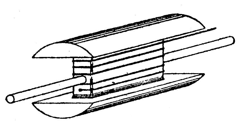
Fig. 2.—Armature.

Fig. 3.
When the armature is not in position, the lines of force will be required to pass from one pole piece to the other through the air, and as they will seek the path of lowest resistance, most of them will pass between the lower points of the pole pieces, where the air gap is short, and where the lines of force are present in the greatest number (Fig. 3).[Pg 257] When the armature is placed between the pole pieces, however, it gives the lines of force a path of still lower resistance, and they will therefore follow it, whatever its position may be. If the armature is free to turn, it will take a horizontal position, as shown in Fig. 4, for then the heads are entirely in contact with the pole pieces, and the greatest possible number of lines of force can take the path offered by the neck of the armature.

Fig. 4.
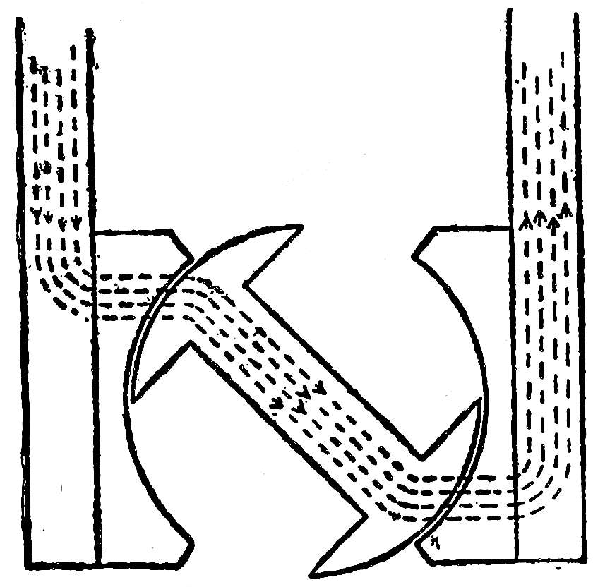
Fig. 5.
When the armature is in this position, the neck is magnetized by the flow of lines of force through it and sets up a powerful magnetic field which is quite distinct from the field thrown out by the field magnets. If the armature is revolved, it takes the lines of force, or most of them, with it, and they continue to flow through the neck as long as one head of the armature is in contact with the north[Pg 258] pole piece and the other head in contact with the south pole piece, for even this long and distorted path, as shown in Fig. 5, is of less resistance than the air gap. The lines of force, however, resist this lengthening of their path, and tend to hold the armature with the neck horizontal, when their passage is easiest. If the armature is turned by hand, it will be noticed that it becomes harder to turn as the neck approaches the vertical position, and if the magnets are sufficiently powerful, a great effort will be necessary. Once vertical, however, the armature hangs, and a still greater effort is required to continue the revolution, for the lines of force have found new paths of low resistance (Fig. 6). Each armature head now forms a bridge between the pole pieces, and the lines of force divide, some going through the upper head and some through the lower. The lines entirely abandon the neck, and in consequence its magnetic field dies out. When these paths are broken by continuing the revolution of the armature, the lines of force again flow through the[Pg 259] neck, and its magnetic field is again established (Fig. 7). This action occurs twice during each complete revolution of the armature, and if the armature is revolved by hand, the two points when the neck is horizontal and the movement easy will be very distinct from the hard points when the neck is going over the vertical position.
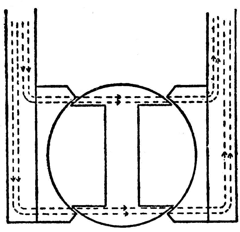
Fig. 6.
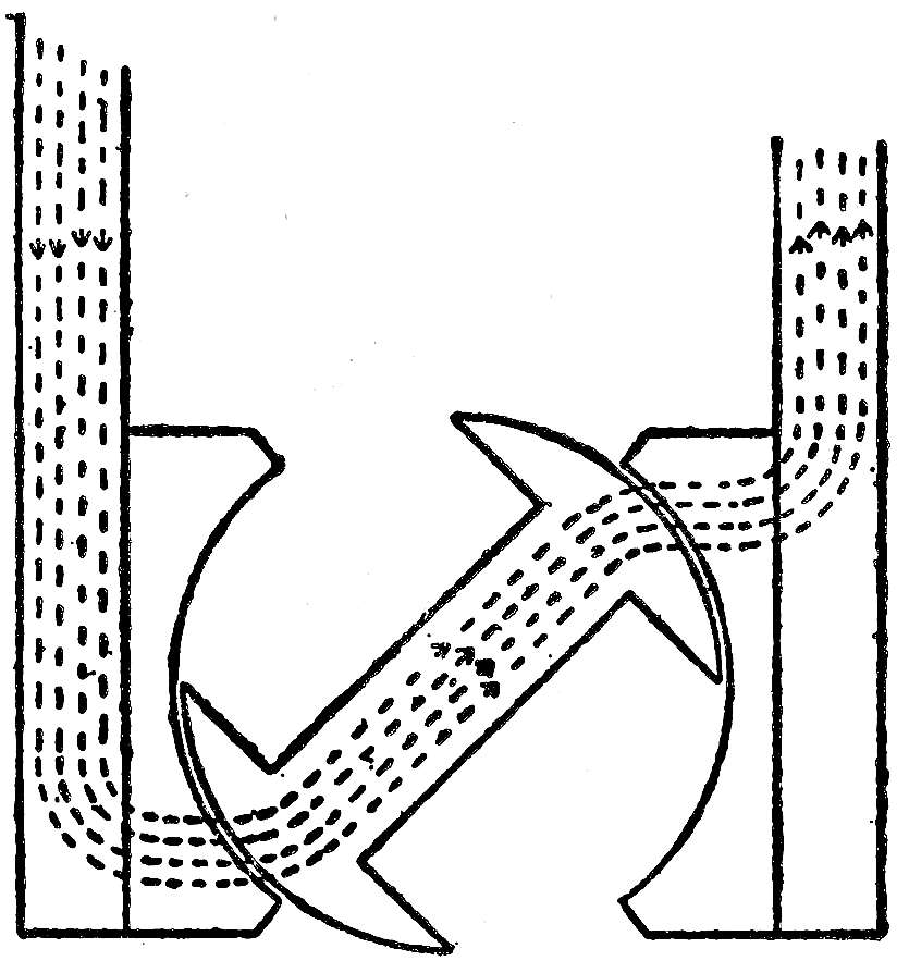
Fig. 7.
In one revolution the neck is twice magnetized and demagnetized; or in other words, the magnetic field set up by the neck as the lines of force pass through it twice changes its strength, being strong when the neck is horizontal and weak when it is vertical. The winding on the armature is affected by this magnetic field, and electric currents are induced in it by these changes in its strength.
The greatest change in the strength of the field occurs as the armature moves into the vertical position, when its heads form bridges between the two pole pieces (Fig. 6). Up to this point the armature neck is strongly magnetized, but its magnetic field dies out as the neck becomes vertical. It is[Pg 260] at this point then that the induced current is at its greatest intensity and becomes sufficient for ignition purposes.
In making an armature the channels are wound full of wire, and this is retained against the action of centrifugal force by two or three short lengths of wire bound around the armature and lying in grooves cut in the heads for that purpose. Disks of brass are also screwed to the ends of the armature core, and assist in making it dust and water proof. The magneto must have a base, and this must be of some nonmagnetic metal, like brass, for if it were made of iron it would provide a convenient path for the lines of force, and they would have no interest in passing through the armature. There must also be bearings for the armature shaft, and these are either plain or ball, set in brass plates screwed to the ends of the pole pieces. A zinc or aluminum plate covers the space over the armature and between the upper edges of the pole pieces, so that the armature revolves in a tunnel that is proof against the entrance of dust and water.
There are, of course, two ends to the wire wound on the armature, but the simplicity of a magneto is increased by grounding one end on the metal of the armature, the other end being brought to the[Pg 261] single terminal (Fig. 2). The circuit is therefore complete when this terminal is connected to any metal part of the magneto; or, as the magneto is mounted directly on the metal of the engine, to any metal part of the engine or frame of the car. The live end of the armature winding is brought out by means of a metal rod passing lengthways through the shaft of the armature, the rod being insulated from the shaft by means of a hard rubber bushing or tube. The terminal of the winding is therefore found at one end of the armature shaft, and the current flows from this revolving part to the stationary binding post by means of a carbon or steel spring that is kept pressed against the end of this rod.
Magnetos are classified as L. T. (low tension) and H. T. (high tension) according to the current that they deliver, the word tension being used to indicate the pressure or voltage of the current, but more accurate expressions would be primary and secondary magnetos. The magneto already described is of the low-tension type, and is used for the make-and-break ignition system, its winding being so proportioned that at maximum speed it delivers a current of from 100 to 150 volts. What is often spoken of as a high-tension magneto is employed[Pg 262] for the jump spark system, a magneto of the type described delivering a current that flows through the primary winding of a secondary induction coil; but this use of the term is erroneous, for while the system delivers a high-tension spark, this is from the coil. The magneto itself is not only of the low-tension type, but its current must be so feeble that the danger of burning out the coil is obviated. A true high-tension magneto has two windings on the armature; one, the primary, consisting of a few layers of coarse wire, over which the very great number of layers of fine wire forming the secondary is wound. This may give a current of from 10,000 to 20,000 volts, and is used for the jump spark ignition system.
These types and their applications will be discussed in the succeeding chapters.
One of the great advantages resulting from the use of a magneto is that for ordinary running it does away with the necessity for the hand advance of the spark. The greater the speed at which a magneto runs, the more abrupt is the change in the strength of the magnetic field, and in consequence[Pg 263] the greater is the intensity of the current delivered. When running at slow speed, the spark produced in the cylinder will be weak and thin; it will be sufficient to ignite the mixture, but the ignition will occur slowly. At high speeds, on the contrary, the intensity of the current produced will be such that a flame rather than a spark will be produced, and ignition will occur much more rapidly and positively. When starting an engine on the magneto, the spark control lever must be advanced more than is necessary for ignition by battery, and the engine must be cranked at such a speed that the magneto will produce a current sufficient for ignition. Once started, it is rarely necessary to move the spark control lever, except for high speeds, for speeding the engine up by opening the throttle will increase the speed of the magneto, and the flaming spark will result in a quicker ignition of the mixture.
Because a magneto does not deliver a continuous current, it cannot be driven by a belt or by friction, for a slight slip would throw it out of time with the engine. The best drive is by gears, for this is positive, and there is a minimum of lost motion. In some cases the magneto is driven by chain and sprocket, and while this prevents slipping, there is[Pg 264] considerable lost motion when the chain is loose enough to run smoothly, and the magneto cannot be timed as accurately as is possible with gears.
If the ignition fails, and the question arises as to the reason, the condition of the magneto may be tested quickly and in a most satisfactory manner. It either gives a current or it does not, and to learn its condition it is only necessary to disconnect it from the ignition system, and to connect one end of a length of wire to its terminal. Holding the free end of this wire in the bare fingers of one hand, and cranking the engine with the other hand, also bare, a shock will be felt as the armature revolves, if it is in good condition. If this test is too strenuous, the free end of the wire may be held lightly against the teeth of a gear while an assistant cranks the engine briskly. As the wire falls from tooth to tooth, a time will come when the point of maximum current coincides with the breaking of the circuit at the gear, and if the magneto is in good condition, a flaming spark will appear.
There is little about a magneto of the type described to get out of order. Oil or dirt between the spring or brush and the end of the conducting[Pg 265] rod may prevent the flow of current, or, what is more unlikely, the wire of the armature may be broken. The last trouble is of rare occurrence, for when winding the wire on the armature it is shellacked, and for all practical purposes the whole becomes a solid mass. The only point where the wire can break is the half-inch of it that is connected to the inside end of the conducting rod that passes through the shaft, and the condition of this may be learned by removing the dust cover and looking. If broken, a drop of solder, carefully applied, will repair the damage.
A question that is frequently asked is regarding the liability of the field magnets to lose their magnetism. If made of the proper material, and handled and used under proper conditions, they should hold their magnetism indefinitely. The strength of a toy magnet may be increased by tearing its keeper sharply away from the poles, and as sharply replacing it, the operation being repeated. When the armature of a magneto revolves, it performs the same office for the field magnets, and it has the effect of keeping them up to strength indefinitely. If the magneto is mishandled, however, it is another story, and an inquisitive or careless worker can almost instantly weaken a field by removing the[Pg 266] armature without taking the proper precautions. The armature, when in position, acts as a keeper, and provides a path of low resistance for the passage of the lines of magnetic force. If the keeper is taken away, the lines of force are required to traverse the higher resistance of the air, and many of them then being overcome, their number decreases and the field becomes greatly weakened. This takes place instantly on the removal of the armature. It is rarely necessary for a chauffeur to remove the armature of a magneto, but when it is required, the first step is the placing of a heavy plate of iron under the arch of the magnets, and in close metallic contact with the pole pieces, the dust plate being removed. This will act as a keeper, and the armature may then be removed. If such a plate of iron is not at hand, both of the end plates may be unscrewed and one of them removed, and then, as the armature is drawn out slowly, small steel tools, or short lengths of iron rod, well cleaned, may be fed in after it, so that the cavity is well filled. If these precautions are taken the armature may be removed with safety, but it is better not to attempt this, and it is never advisable to detach the magnets from the base or pole pieces. So much damage may be done to a magneto by an unskilled man, that some of the[Pg 267] manufacturers go to the length of equipping their magnetos with seals, the breaking of which is evidence that the machine has been tampered with, and that someone is directly to blame if it does not deliver current.
When an engine is equipped with a double system of ignition, or when there are two sources of current, one being a magneto, the greatest care must be taken to prevent even the momentary flow of the battery current through the armature winding, for this will result in the demagnetization of the field. The same trouble will result if the magneto current is led through the winding of a primary induction coil in the hope of intensifying the current. Should the battery current flow through the armature winding, the core would be magnetized, for it would then be an electro-magnet, and the magnetic field set up by the armature under such conditions would overcome the less powerful field set up by the field magnets and their strength would instantly be reduced.
It is very essential to keep the armature bearings thoroughly lubricated in order that there may be as little wear as possible. The clearance between the armature heads and the pole pieces is so slight that a trifling amount of wear in the bearings would permit[Pg 268] the two to rub or strike. The best magnetos are equipped with ball bearings, provided with wick feeds that keep them lubricated, but even with these the lubrication must be watched. Oil cups are provided, which must be kept filled, but it must be remembered that an excess of oil may make trouble in working its way into the armature winding and destroying the insulation. In some cases the oil cups are provided with an overflow, which prevents excessive oiling and the collection of surplus oil around the bearings.
In utilizing the current of a magneto for ignition purposes, the circuit is so arranged that it is first closed and then opened, the closing of the circuit permitting the current to flow, and the breaking of the circuit resulting in a spark at the break. The closing and opening of the circuit is due to the action of the igniter, which is a device located in the cylinder wall, one end projecting into the combustion space and the outside end bearing the parts by which it is operated. The two chief parts of an igniter are the stationary and movable electrodes, so arranged and connected that when the movable[Pg 269] electrode comes into contact with the stationary electrode the circuit is closed, and when it moves out of contact the circuit is broken.
The stationary electrode is a steel pin or screw passing through the cylinder wall, and carefully insulated from it by a tube or bushing of mica or other insulant that is proof against the heat and pressure produced in the combustion space. The current developed by the magneto is led to this stationary electrode. The movable electrode rocks in a bearing in the cylinder wall, the inside end of its short shaft carrying a finger that touches or separates from the stationary electrode as the shaft is rocked. The outer end of the short shaft carries one or two short arms by which the shaft is moved. The operation of the igniter is due to the action of a cam on the half-time shaft, which moves a tappet rod that in turn acts on the arm controlling the movable electrode.
When the cam is not acting on the tappet, the movable electrode is held out of contact with the stationary electrode, and there is consequently no circuit for the current. As the tappet is moved by the revolution of the cam, the movable electrode is freed and is brought into contact with the stationary electrode by the action of a light spring.[Pg 270] This closes the circuit, and the current flows. The further revolution of the cam separates the movable electrode from the stationary, and the sudden breaking of the circuit results in the production of a spark between the two.
[Pg 271]
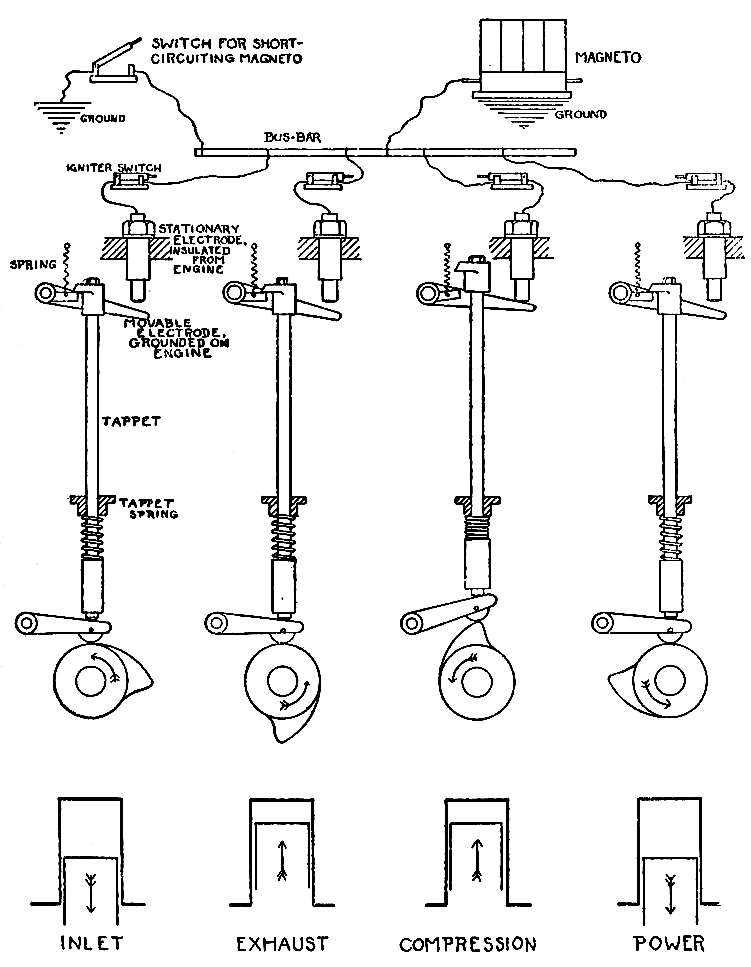
Fig. 8.—Make-and-Break System.
There is a great variety in the construction of igniters, but the operation is the same in all. Once in its revolution the cam operates the movable arm of the igniter, permitting it to touch the stationary electrode, and this establishment of the circuit is followed by its rupture as the continued movement of the cam causes the tappet again to operate the movable electrode. A better spark for ignition purposes is obtained when the movable electrode is moved out of contact with the stationary electrode sharply than when it is moved slowly, and for this reason the parts are so arranged that the tappet strikes the movable electrode a blow instead of pushing or pressing it. This construction is shown in Fig. 8. When the cam is not acting on the tappet, the head on the tappet holds the movable electrode away from the stationary, against the action of a light spring. As the cam lifts the tappet, the tappet head releases the movable electrode, and the light spring draws it upward and against the stationary electrode, establishing the circuit. When [Pg 272]the tappet drops off the cam, it is brought down sharply by the tappet spring, and its head strikes the movable electrode a sharp blow that results in the sudden breaking of the circuit.
In some types, the movable electrode comes into contact with the end of the stationary electrode, which is then a screw, and the distance between them may be adjusted by screwing it in or out. In other types, contact is made with the side of the stationary electrode, in which case the adjustment of the distance is provided for on the movable electrode. This distance should be about one sixteenth of an inch, for this is ample for the production of a satisfactory spark, and a greater distance will result in the more rapid burning of the contact points.
In multicylinder engines, the current from the live end of the armature winding is led to a bus-bar of conducting material that serves to distribute it to the igniters. The stationary and insulated electrode of each igniter is connected to this bus-bar by a short length of wire that either leads through a switch of ordinary construction, or is provided with a plug on its end that fits into a socket on the bus-bar and serves the purpose of a switch by which the igniters may be thrown out of circuit[Pg 273] when it is desirable. As the magneto is grounded when it is placed on the engine, and as the movable electrode of the igniter is also grounded on the engine, a circuit for the current is provided only when a movable electrode is in contact with a stationary electrode. The construction of the cam shaft is such that only one igniter at a time makes contact, which occurs during the compression stroke, so that the rupturing of the circuit will occur at the point in the compression stroke when the spark is required for ignition.
To cut off the ignition circuit for the purpose of stopping the engine, it would be bad practice to break the contact between the magneto and the bus-bar, for while this would bring the desired result it might result in the injury of the magneto, as there would then be no circuit for the current that the magneto would still be developing. The best practice is to short-circuit the magneto, and this is provided for by means of a simple switch, one point of which is grounded, and the other connected to any insulated part of the ignition system; the magneto terminal, bus-bar, or other. When this switch is closed, a circuit is provided for the magneto current, which, in the arrangement shown in Fig. 8, flows from the magneto to the bus-bar,[Pg 274] to the switch (when closed), to ground, and back to the magneto. If this circuit is provided, the current will follow it, abandoning the paths across the igniters as they operate, and the production of sparks ceasing, the engine will come to a stop.
To obtain successful results, the spark must be produced at the correct point in the compression stroke, and this requires such adjustment of the igniters that the movable electrode breaks the circuit at this point. Because the magneto delivers a fluctuating current, it is clear that the most satisfactory spark will be produced when it is so set that it will be delivering its maximum current at the instant that the igniters separate. As most of the running of a car is done on an advanced spark, the point of maximum advance must be determined in order to set or adjust a low-tension ignition system. This point varies with different engines; in a large proportion the piston has a “lead” of one half inch, while in a smaller number the “lead” varies from this to three quarters of an inch. By this it is meant that when advanced, the spark occurs when the piston still has one half inch to travel to reach top[Pg 275] dead center of the compression stroke, or anything up to three quarters of an inch, as the case may be. Inquiry of the manufacturers regarding this point will secure the information, but if this is not possible, the point may be found by experiment.
The first step is to bring one of the pistons to within one half inch of top dead center of the compression stroke. This position may be determined by dropping a stiff wire through a compression relief cock or other opening in the cylinder head, so that it rests on the piston and is moved by it. The crank shaft of a four-cycle engine must make two revolutions to complete the cycle in one of the cylinders, and during these two revolutions the piston will twice pass top dead center, as will be shown by the movements of the wire. It is necessary, however, to distinguish between top dead center of the compression stroke and top dead center of the exhaust stroke, and this may be accomplished by watching the stem of the exhaust valve. When the wire shows that the piston is moving toward top dead center, and the exhaust valve stem shows the valve to be open, the piston is known to be making the exhaust stroke, and to get it to top dead center of the compression stroke it is necessary to continue the revolution of the crank shaft while the[Pg 276] piston moves downward on the inlet stroke, and again upward on the compression stroke. During this second upward stroke the exhaust valve stem will not move, showing the valve to be closed. Cranking must stop when the lack of movement of the wire shows the piston to be at top dead center, and then the crank shaft must be turned backward by means of the flywheel until the piston has moved down one half inch. This may be determined by making a mark on the wire and holding a rule firmly in such a position that as the wire follows the piston the mark will move along the graduations. When the mark has moved down one half inch below top dead center, the movement of the crank shaft must be stopped so that the piston is held in that position.
Place the spark control lever in the advanced position, when the nose of the cam should be just ceasing to act on the tappet. The movable electrode must then be adjusted so that it is in the act of separating from the stationary electrode, and this is performed by shortening or lengthening the tappet, or otherwise setting the parts so that the tappet head is in contact with the outside arm of the movable electrode and beginning to move it away from the stationary electrode.[Pg 277] This point may be accurately determined by the use of an electric bell circuit. Connect a bell with three or four dry cells, grounding the free terminal of the battery on the engine. Then breaking any connection between the igniter terminal and the ignition system, connect the free terminal of the bell to the igniter. The circuit will then consist of battery, bell, igniter, and ground return, and the bell will ring when the movable electrode is making contact with the stationary. Having adjusted the movable electrode so that it is approximately correct, it may be tested by cranking the engine. The bell should begin to ring during the compression stroke, and should stop ringing when the marks of the wire show the piston to be one half inch from top dead center. The igniter of each cylinder must be adjusted separately, and when tests have shown them to be correct, the lock nuts must be set up to hold them in position.
In attaching the magneto to the engine, means must be provided for driving it at the proper speed. In a four-cylinder engine, two revolutions of the crank shaft are necessary for the production of a cycle in each of the cylinders, two power strokes occurring in each revolution. As the magneto delivers its maximum current twice in each revolution[Pg 278] of the armature, it must be driven at the speed of the crank shaft, and as the drive is usually taken from the cam shaft, the gear on the magneto must have half as many teeth as the gear on the half-time shaft with which it meshes. To set the magneto, the crank shaft should be revolved until one of the pistons (it makes no difference which) is in the firing position; that is, the position for which the igniter is set to open. The armature should then be revolved by hand until it is just past the vertical position of Fig. 6, with about one sixty-fourth of an inch of space showing between its rear edge and the edge of the pole piece from which it is moving. This can most easily be accomplished by removing the dust cover and reaching under the arch of the field with the fingers. Holding the armature in this position, its driving gear should be slipped into mesh with the gear on the half-time shaft.
In some makes of magnetos the gear is keyed to the armature shaft, which determines its position in relation to the armature. In this case, the gears must be meshed as close to the indicated position as possible. In other designs the magneto is driven by a positive clutch, so that it is impossible to mesh it in any but the correct position. In Bosch magnetos[Pg 279] there is no key, but the shaft is tapered to fit a tapered hole in the gear, so that a very exact setting of the magneto is possible.
When the gear is keyed to the armature shaft, the closeness of the setting depends on the thickness of the teeth; the thinner the teeth, the closer it is possible to adjust the magneto. If the armature gear has an uneven number of teeth, however, it is possible to make the setting by one half the thickness of a tooth. If it is found that the thickness of the teeth is such that the armature cannot be set correctly, give the armature and its gear a half turn, when, if the number of teeth is odd, it will be found that a tooth on one side corresponds to the space between two teeth on the opposite side.
Having set the magneto and drawn up the nut securing the gear to the armature shaft, the system may be wired by running a wire from the terminal of the magneto to the bus-bar, and other wires from the bus-bar to each of the igniter terminals. The short circuiting switch should also be connected up, the running of its wires depending on convenience.
The system installed, it should be tested. With the system adjusted as indicated, the engine should start, and a very short run will show if it is correct.[Pg 280] If it does not respond to advancing the spark, or if its operation is not satisfactory, a readjustment should be made, giving the piston a lead of one eighth of an inch more, or five eighths of an inch in all, with the spark advanced. If this shows an improvement, but the engine still does not develop its full power, the operation may be repeated, the piston being given more lead by one sixteenth of an inch.
If the compression is not the same in all of the cylinders, a closer adjustment of the igniters may be made that will improve the operation of the engine, the tappet of the high compression cylinder being adjusted to operate the movable electrode slightly before the others, so that the larger volume of mixture will have more time in which to burn. The switches through which the igniters are connected to the bus-bar may now be brought into use, and when three of them are open the engine should run on the single cylinder of which the circuit is complete. Testing the cylinders in this way, running one at a time, gives an opportunity for comparing their action, and for noting those in which the power is weak. If the weakness is due to ignition trouble, it may be corrected by a further adjustment of the tappet.
[Pg 281]
Failure of ignition due to magneto trouble has already been described.
Any short circuit of the system will prevent ignition, for the current will not flow across the igniters if another path is open to it. Short circuiting may be due to the chafing of the insulation of the wires, to a frayed end of a stranded cable making contact with the metal of the engine, to the carbonization or breaking of the insulation around a stationary electrode, or to the sticking of a movable electrode in contact with a stationary. Operating the igniters by hand will show the presence of this last named condition, and inspection of the insulation and terminals the presence of any defects. Loss of power is frequently due to the leakage of compression around the plate carrying the igniter, around the stationary electrode, or through the bearing in which the movable electrode rocks. The side of the bearing toward the combustion space is built like a valve, and when worn may be ground to a seat.
If the engine runs well at low speed, but misses at high speed, the fault may be located in faulty insulation of one of the stationary electrodes, which[Pg 282] holds the low-pressure current developed by the magneto at low speed, but fails to retain the higher pressure developed when the speed is increased. The faulty igniter may be located by running the engine one cylinder at a time.
The heat developed by the spark is very great, and provisions must be made to preserve the contact points from undue corrosion. These points are usually made of platinum, or of an alloy of platinum and iridium, and must be kept clean and smooth. The spring that draws the movable electrode against the stationary must not be too strong or it will bring the contacts together with sufficient force to batter them out of shape. This spring should be of sufficient strength to bring them together promptly, but without undue force. The tappet spring should be of considerable strength, in order that the separation of the electrodes may be quick and positive.
After long running the contacts will become worn to such an extent that the spark occurs too late in the stroke to permit the engine to develop its full power. This may be corrected by readjustment of the tappets, so that ignition takes place earlier. A wearing of the outside arm of the movable electrode, or of the tappet head, will have the same effect.
[Pg 283]
Another cause of failure will be the weakness of the spring of the movable electrode, which is so weakened that it will not do its work at high speed.
The advantages of a magneto as a current producer for the low-tension system pointed the way to its adoption for the jump spark system also, but it was at once recognized that it would be impossible to lead the current direct to the primary winding, as the current from a battery is used. The reason for this is that while the battery delivers a current of constant value, the current obtained from a magneto is fluctuating, its intensity depending on the positions of the armature as it revolves, and the speed at which it is driven. A current is induced in the secondary winding of the coil as the magnetic field set up by the core changes its strength, and as has been explained, the induced current is strongest when the greatest change in the strength of the field occurs in the shortest possible time. The effect of the flow of the magneto current through the primary winding of the coil would be to magnetize and demagnetize the core slowly, as the[Pg 284] magneto current increased to its maximum and died away to the minimum, and these gradual changes in the magnetic field of the core would induce currents in the secondary that would be too feeble to produce ignition of the charge. When a battery is used with a coil, the operation of the vibrator produces rapid magnetizations and demagnetizations of the core, but as the field set up by the core dies away more rapidly than it is established, the greatest current is induced by the breaking of the circuit. In the best known method of applying a magneto to the operation of a secondary coil, the magnetization of the core is caused to occur with exceeding rapidity, and the current induced in the secondary winding as this occurs is sufficient for ignition.
This is known as the Eisemann system, and is in very general use. A diagram illustrating the connections is shown in Fig. 9.
[Pg 285]
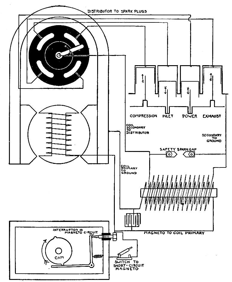
Fig. 9.—Eisemann Ignition System.
The magneto is of the usual type, but the winding is so proportioned that the current is of lower voltage than is delivered by what has been described as the low-tension type of magneto. One end of the winding is grounded on the metal of the armature, and the live end is carried to a contact screw. The current flows to this screw, and from there two [Pg 286]paths are presented by which it may flow back and complete its circuit. One of these paths leads through the primary winding of a secondary coil, and the other through a lever that for the greater part of the revolution of the armature touches the contact screw. The lever is grounded on the metal of the magneto, and when it touches the contact the circuit that is then completed is short and of low resistance, and the current follows it in preference to the circuit of higher resistance through the primary winding of the coil. The flow of current is thus from the armature winding to the contact screw, which is insulated from the metal of the magneto, to the lever, and by the ground back to the winding. Attached to the end of the armature shaft, and so placed that it operates the lever, is a cam with two projections, these projections being arranged to move the lever away from the contact screw. This arrangement is called the interruptor, and by its operation it closes and opens the low-resistance circuit by which the magneto current may flow.
When the armature is horizontal, and during the time that it is approaching the vertical, the circuit is closed through the interruptor, but when the armature reaches the position in which it gives its maximum[Pg 287] current, the interrupted is opened by the cam, and the current, losing its low-resistance circuit, is required to flow through the primary winding of the coil, for that is the only path by which it can return to the armature winding. The sudden flow of this current through the primary winding results in the production of a powerful magnetic field around the core, and this rapid growth in the strength of its field induces a current in the secondary winding that is sufficient for the ignition of the charge. As the magneto current is at its maximum twice during each revolution of the armature, the cam is arranged to open the low-resistance circuit at such periods that each maximum is required to flow through the primary of the coil.
In applying this system to a multicylinder engine, it is necessary to distribute the secondary current to the different cylinders, so that a spark will be produced in each as it is required. This is accomplished by means of a secondary distributor, consisting of a revolving conductor to which the secondary current is led, and a stationary contact for each cylinder arranged in a circle, to be touched as it revolves. These stationary contacts are connected with the spark plugs, according to the firing order of the engine. During one revolution of the[Pg 288] distributor, a spark is produced in each of the cylinders, and as two revolutions of the crank shaft are necessary in order to have power strokes occur in all of the cylinders, the distributor must revolve at half the speed of the crank shaft. The magneto produces a current that is sufficient for ignition twice during each revolution of the armature, and therefore, for four cylinder engines, must run at the speed of the crank shaft. For the sake of compactness, the distributor is built into the magneto, its shaft being carried in bearings that support it above the armature and under the arch of the field magnets. It is geared to the armature so that the two revolve in a fixed relation to each other, and in order that the distributor may run at half the speed of the armature, its gear has twice the number of teeth of the gear on the armature shaft that drives it.
The secondary induction coil used is similar in construction to the coils used for ignition by battery, except that it is heavier, and has no vibrator. The period during which the magneto is delivering its maximum current is so brief that there would hardly be time for a vibrator to get into action, and even if this were not the case, the making and breaking of the circuit by the vibrator is not necessary, as the single change in the strength of the[Pg 289] magnetic field set up by the core is so abrupt that the current induced by it is sufficient for the purpose.
The strength of this secondary current is such that it is necessary to provide a circuit for it if by any accident or oversight the circuit through the distributor or spark plugs is interrupted, as would be the case should one of the secondary wires become disconnected. This is taken care of by what is known as the safety spark gap, which is a gap provided between the secondary terminals of the coil, or between the live end of the secondary winding and the ground. This safety spark gap, in the case of the coil furnished by the Eisemann company, takes the form of two flat pieces of brass, each in contact with one of the secondary terminals of the coil, their pointed ends being separated by a distance of about half an inch. When there is no interruption of the secondary circuit, and the parts of the secondary system do not present undue resistance to the flow of the current, the higher resistance of the air space between the points of the safety spark gap prevents the current from jumping between them, but should one of the secondary cables become disconnected, the pressure of the current will rise to a point that will enable it to jump the[Pg 290] gap between the two points. If it were not for this safety gap, an interruption of the secondary circuit would make the pressure of the current rise to such an extent that there would be great danger of a spark passing inside of the coil, rupturing the insulation.
As the magneto is received from the makers, the parts will be in a fixed relation to each other; when the armature is vertical, and held in that position by the lines of force, the cam is in the act of opening the primary interruptor, and the revolving part of the secondary distributor has moved into contact with one of the stationary contacts about one thirty-second of an inch.
The interruptor of the magneto can be utilized as the timer for an ignition system by battery and coil, the secondary current being distributed to the cylinders by the distributor. A better arrangement, however, requires the use of two coils, and a timer which is carried on the rear end of the distributor shaft. The coil for the battery system is provided with a vibrator, and connections are made in the manner usual with a system composed of these parts. The coil is in a case that also contains the non-vibrator coil for the magneto system, and the two wirings are separate and distinct with the exception[Pg 291] of the secondary connection between the coil box and the revolving parts of the distributor, which is common to both.
While little change in the position of the spark is required for this system, provisions are made by which it may be advanced or retarded. In one system, the interruptor is operated by a groove in the face of the cam disk, a pin on the end of the interruptor lever following the groove and being moved by the irregularities. In this case, the advance and retard of the spark is obtained by rotating a plate carrying the interruptor in one direction or the other, so that the lever is moved earlier or later in the revolution of the cam. In another type the gear driving the armature is not attached direct to the armature shaft, but to a sleeve surrounding the shaft, and the pulling out of a second sleeve between the two alters the position of the armature in relation to the driving gear, resulting in the advancing or delaying of the moment when the maximum current is produced.
In setting up a system of this description, the firing order of the engine must be ascertained, and[Pg 292] this may be done by watching the order in which the exhaust valve stems move as the engine is slowly cranked. Piston No. 1 must then be brought to top dead center of the compression stroke, and about one thirty-second of an inch down on the power stroke, being stopped in this position. With the magneto screwed into place, the covers of the interruptor and distributor may be removed, and the armature revolved by hand in the direction in which it will be driven, until the interruptor opens, the spark control being in the most retarded position. A mark on the interruptor will come into line with a mark on the casing at the instant that the interruptor breaks contact. The magneto gear should then be meshed with the gear that drives it, and the lock nut set up.
The connection between the live end of the armature winding and the interruptor is arranged by the maker, but it is necessary to make connections between the magneto and the coil. A terminal will be found in the casing close to the stationary contact screw, and this is to be connected with one of the primary terminals of the coil, the other primary terminal either being grounded on the engine or the magneto, according to the construction. The moving part of the secondary distributor may then[Pg 293] be connected with the secondary terminal of the coil. If the coil has but three terminals, two primary and one secondary, there are no further coil connections to be made, but if, as is sometimes the case, there are two secondary terminals, the free one is to be grounded on the engine.
An inspection of the distributor will show that the revolving part is beginning to make contact with one of the stationary points, and this point is to be connected to the spark plug of the cylinder in which the piston is at top dead center of the compression stroke. The next distributor point in the direction of rotation is to be connected with the spark plug of the next cylinder to fire, the remaining distributor points and spark plugs being connected in the order of firing.
Magnetos of this type are built to run in either clockwise or counter clockwise, and the two are not interchangeable. The direction in which the magneto is to be driven is indicated by an arrow stamped on the gear casing or end plate.
When the system is properly installed, the motor should start on a quarter-turn of the crank shaft, the crank being given a quick upward jerk. If it does not, the setting is incorrect, the connections are improperly made, or there is too great a distance[Pg 294] between the points of the spark plugs. This distance should be one sixty-fourth of an inch.
The bearings of the armature and secondary shafts must be kept well lubricated, as well as the parts of the interruptor that require it.
Every few weeks, depending on the use, the carbon or steel brush bearing against the live end of the armature shaft must be wiped off with gasoline, and the same care must be given to the distributor contacts and to the platinum contacts of the interruptor.
When the platinum contacts of the interruptor become worn down after long use, or if for any other reason they require readjustment, they must be set so that the distance between them at the moment that the cam holds them apart is not more than one one-hundredth of an inch. This space may appear to be very small for the work that is to be performed, but it will be sufficient, and a greater distance will result in sparking that will burn down the contacts. In the Eisemann magneto, the adjustable contact is held by two nuts, and small open end wrenches are provided to fit. A wrench should be applied to each[Pg 295] of these nuts, and the lower or lock nut loosened. This will free the upper nut by which the adjustment may be made, and the lock nut may then be tightened. The contact faces of the platinums should be kept flat and smooth, and true to each other, so that they come together squarely. If they are pitted after long use they may be faced off with a dead smooth file, but this is a job that requires great care, and must only be done under the most favorable conditions. When completely worn down they should be replaced with new ones.
Should the engine show a tendency to miss, the first suspicion, if the magneto contacts are known to be correct, should fall on the spark plugs, and the easiest method of testing them out is to replace them with new ones. After considerable use, the spark plug points will burn off, and the size of the gap will increase to such an extent that the spark will find less resistance in traversing the safety spark gap than the gap in the plug.
In order that the ignition may be cut off for the purpose of stopping the engine, a switch is always provided by which the magneto may be short circuited,[Pg 296] one pole of the switch being connected to the magneto terminal, or live wire, and the other pole grounded, as shown in Fig. 9. When this switch is closed, the magneto current flows through it in a closed circuit, and as it abandons its path through the interruptor there will be no further action in the coil, the ignition of course ceasing. This switch is often located in the rim or arm of the steering wheel, so arranged that pressing on a button closes the circuit and diverts the magneto current from the coil.
Any accidental short circuit of the magneto current will produce the same effect, and in case of the abrupt cessation of ignition, this is one of the probable causes. A short circuit in the secondary will usually make itself known by the snapping of the sparks as they pass through broken insulation or from a frayed cable end.
The remarks on general magneto troubles and care already made on page 254 also apply to a magneto of this type, and the same rules regarding the protecting of the circuit of the lines of the field must be borne in mind.
[Pg 297]
A high-tension magneto differs from the types described in that the armature has a double winding; one, the primary winding, consisting of a few layers of coarse wire, and the secondary winding, placed over the primary, consisting of many layers of very fine wire. As the armature revolves, a current is induced in the primary winding, the circuit of which is kept closed until the armature reaches the position in which the induced current is at its greatest value. An interruptor operated by a cam then opens the primary circuit, and the sudden demagnetization of the armature core that results induces in the secondary winding a current of high pressure that is quite sufficient to jump the gap in the spark plug and to cause ignition of the mixture. The construction of the armature is more delicate than is the case with a low-tension magneto, for the secondary winding must have a large number of layers, and to permit this in the limited space, the wire must be fine. In addition, it must be insulated with the greatest care, for the intensity of the current produced will enable it to seek out and to break down any weakness that exists. There must also be two brushes, one for the primary current and[Pg 298] one for the secondary, which complicates the construction.
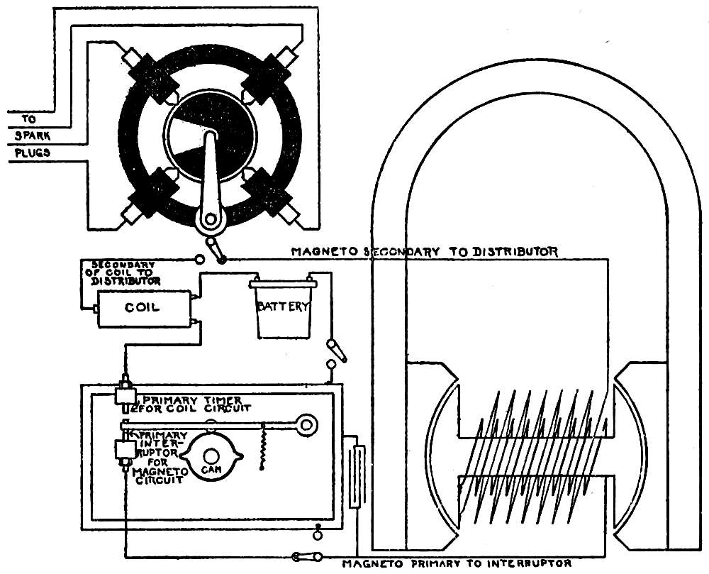
Fig. 10.—Wiring Diagram, H.-T. Magneto Interchangeable with Secondary Coil.
A magneto of this type is shown in diagram in Fig. 10. In this case, the inner ends of both the primary and secondary windings are grounded, the live end of the primary being connected with the insulated contact of the interruptor, and the live end[Pg 299] of the secondary leading to the rotating part of a secondary distributor. For the greater part of the revolution of the armature, the cam on the armature shaft permits the interruptor to maintain a closed circuit, but as the current reaches a maximum the cam breaks the circuit, and the flow of the primary current ceases. During this time, the secondary circuit has been open, the moving part of the distributor being out of contact with the stationary points. Under the law of induction, a current will only be induced in a closed circuit, and there is therefore no action in the secondary winding. When the primary current is at its maximum and its circuit is broken, another condition exists, for then the secondary distributor is making contact, the only gap being in the spark plug, but the sudden demagnetization of the armature core as the primary circuit is broken, and the additional effect as the armature passes the vertical position, induces in the secondary winding a current of great intensity that passes to the spark plug by way of the distributor, returning to the winding by the ground.
The parts of the interruptor are carried on one of the end plates of the magneto, and the secondary distributor revolves in bearings that support it under the arch of the magnets.
[Pg 300]
In the diagram shown provisions are made for a double ignition system, the operator having his choice of ignition by high-tension magneto direct or by battery, timer and coil. In practice, the three switches shown operate together. When magneto ignition is desired, the switch between the battery and ground is opened, and the switch at the secondary distributor thrown into contact with the point connected with the secondary terminal of the magneto. The third switch is thrown to make contact between the primary terminal of the magneto and the interruptor. If battery ignition is desired, the switch on the magneto primary is thrown to the point through which it is grounded, and the primary and secondary switches of the battery circuit closed. The upper contact points of the interruptor are then utilized to close primary circuit of battery, and the secondary current induced in coil is led to distributor. This complication of switches is necessary to prevent possibility of the battery current flowing through the armature winding, and to provide a short circuit for the primary of the magneto. If the engine is running on magneto ignition, it is stopped by throwing the primary switch to the point by which the primary is grounded. If running on battery, the circuit is broken in the usual way.
[Pg 301]
The current from a high-tension magneto is of such intensity that the small points of an ordinary spark plug would quickly be burned, and it is necessary to provide plugs with heavy points, which will stand the work. The distance between the points should be about one sixty-fourth of an inch.
The Bosch magnetos, which are perhaps in more general use than any other, are built on similar lines to the magneto just described, except that the grounded end of the secondary winding, instead of being attached to the metal of the armature, is connected to the live end of the primary winding, as shown in Fig. 11. The live end of the primary is brought out through a conducting rod passing lengthways through one end of the armature shaft, from which the current flows to the stationary contact of the interruptor. While in other magnetos the interruptor parts are stationary and operated by a moving cam, in this type the interruptor parts revolve with the armature, and the moving arm is operated by two fiber wheels as it drags around the inside of a stationary ring. By rotating the ring and the two wheels the interruptor is caused to operate sooner or later in its revolution, this giving the advance and retard of the spark.
[Pg 302]
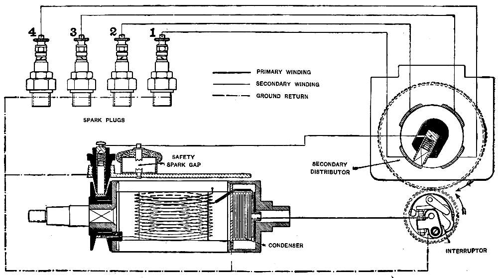
Fig. 11.—Wiring Diagram, Two-Spark Magneto.
The other end of the armature shaft carries the [Pg 303]collecting ring for the secondary current, this consisting of a hard rubber disk around the surface of which is a metal ring to which the live end of the secondary winding is connected. A carbon brush is kept pressed against this metal ring by a light spring, and the current is thus led off to the revolving part of a secondary distributor.
The interruptor keeps the primary circuit closed until the current induced in the primary winding is at its maximum, when the opening of this circuit causes the rapid demagnetization of the core, and a powerful current is induced in the secondary, which flows to the spark plug with which the distributor is making contact.
A safety spark gap is applied between the brass strip that conducts the secondary current from the collecting brush to the distributor, and the metal of the magneto. The necessity for this device has already been explained, and it is essential that a magneto of this type should be so provided, because of the intensity of the current.
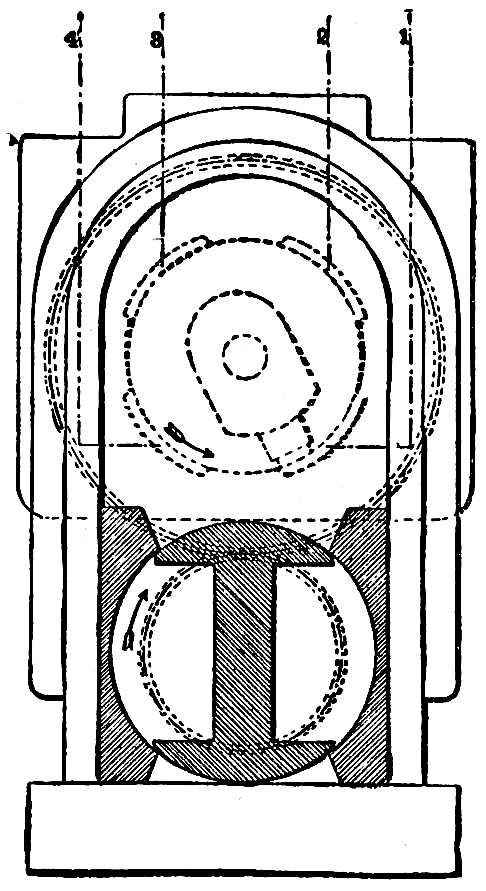
Fig. 12.—Timing Diagram, Two-Spark Magneto.
In setting up a system of ignition with a magneto of this type, the firing order of the engine must be[Pg 304] observed, and then one of the pistons brought to the point in the compression stroke that it will occupy when the spark is at the greatest advance. As has been explained in the case of engines equipped for the make and break system, this point will usually be from one-half to three-quarters of an inch before top dead center, the greater proportion of designs placing it at one-half an inch. The driving gear of a Bosch magneto is not keyed to the armature shaft, but shaft and gear are tapered, so that when the nut is drawn up tight there is no possibility of slipping. After the magneto is secured in position its gear may be meshed with the gear that is to drive it, but without drawing up the nut. The armature may then be turned by hand until it is in the vertical position, where it will be retained by the lines of force (Fig. 12), and the gear nut drawn up tight. If this position of the armature[Pg 305] cannot be obtained by the sense of touch, it may be exposed to sight by the removal of the bridge that carries the safety spark gap, and of the dust cover that protects the space between the upper sides of the pole pieces.
The loosening of the three-armed frame on the front of the magneto will permit the removal of the covers of the interruptor and timer, and it will be seen that the moving part of the distributor is beginning to make contact with one of the stationary pieces; this should be connected to the spark plug of the cylinder that is in the firing position. The other contacts of the distributor should then be connected to the remaining spark plugs in the order of firing.
Ignition is cut out by short-circuiting the primary winding, and a binding post will be found on the front of the magneto under the three-pronged frame to which is connected the wire that leads to a switch making a ground connection when closed.
The armature and distributor shafts run on ball bearings, and these require the application of a few drops of oil twice a month. The interruptor is designed[Pg 306] to operate without oil, and there is therefore little danger of oil working its way into the winding.
The carbon brushes must be wiped off with a little gasoline occasionally, and these are arranged in such a manner that they are easy of access.
The platinum contacts of the interruptor must be kept free from dirt and oil, and when, after long use, they become worn and uneven, they must be faced off by the use of a dead smooth file. The distance between them when separated by the action of the fiber rollers must not be more than one sixty-fourth of an inch, and this may be adjusted by means of the nuts. Accompanying each magneto is a small open end wrench for this purpose, to which is pivoted a leaf of steel that is to be used as a gauge for this distance.
This same measurement applies to the spark plugs, the points of which must provide a gap of not more than one sixty-fourth of an inch.
If there is an abrupt failure of ignition, it is probable that the primary is short-circuited, and this can only occur on the wire that leads to the short-circuiting[Pg 307] switch, for the other parts of the primary circuit are inclosed and protected against injury.
In case of the missing of one cylinder only, the trouble will usually be found in the plug, which may be short-circuited by a carbon deposit, or because the intense heat of the spark has fused the metal, resulting in the formation of a globule of metal between the spark points. Too great a distance between the points, more than one sixty-fourth of an inch, will prevent the passing of the spark, which will then be seen in the safety spark gap.
A miss in different cylinders may be due to defective insulation of the wires, but if these are in good condition the fault may be looked for in the magneto. The place where trouble is usually experienced is in the interruptor, which may become dirty, or the contacts may be worn down or loosened from the vibration. Fouled contacts in the distributor may also lead to a miss-fire, and this will be corrected by wiping the parts with gasoline. If all of these parts have been examined and found correct, it is inadvisable to examine further into the magneto, for inexperienced handling will be likely to injure the delicate parts. It is better to place it in the hands of a man whose shop is equipped for the work.
[Pg 308]
All of the magnetos described have been of the type in which the armature revolves, and two ignitions are secured per revolution. These are known as two-spark magnetos, or crank-shaft speed magnetos, from the fact that for four cylinder engines the magneto runs at the speed of the crank shaft. This is in distinction to the Bosch four-spark, or cam-shaft speed, magnetos, in which the armature as well as the field is stationary. This magneto for its simplicity, freedom from trouble, and workmanship, has few equals for the high-tension ignition of an internal combustion engine.
[Pg 309]
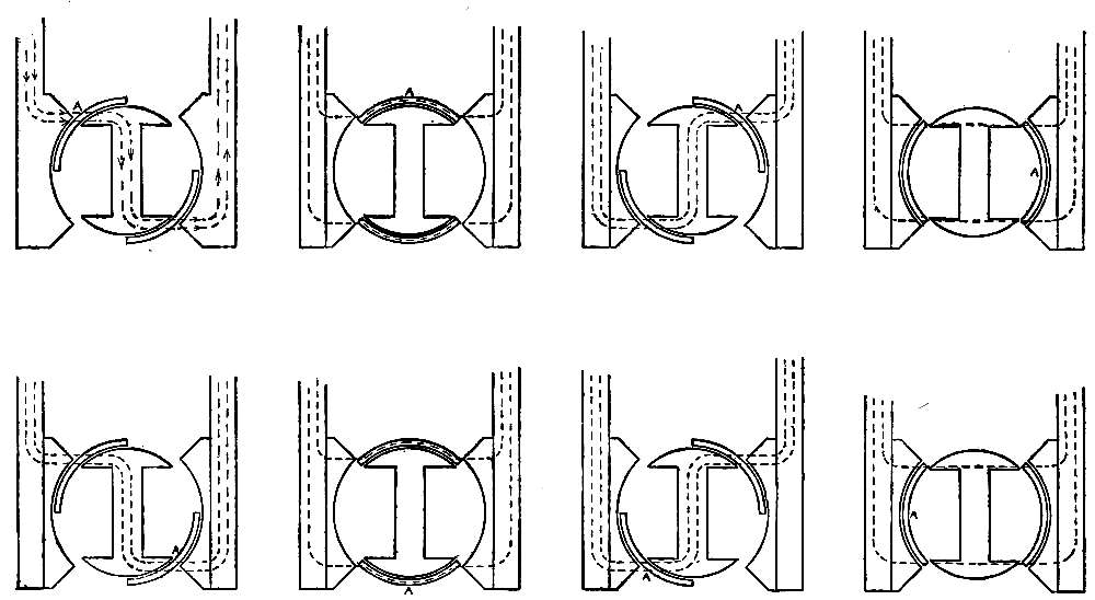
Fig. 13.—Diagrams showing Position of Shield Revolving about Armature.
The armature in this magneto is of the usual type, and is stationary, with the armature neck in a vertical position. Around the armature, and between it and the pole pieces, revolves a soft iron shield in two sections, these being the length of the armature and the same width as the heads. As it revolves, it forms bridges between the pole pieces and the core of the armature, the lines of force flowing through it as well as through the armature. The diagrams of Fig. 13 show the positions of the shield as it revolves about the armature. In the first position, one segment of the shield forms a [Pg 310]bridge between the pole piece and the upper armature head, while the other segment is bridging the space between the lower head and the other pole piece. When in this position, the lines of force flow through the neck of the armature and magnetize it so that it sets up its own field. When the shield revolves so that it covers the heads, the lines of force abandon the neck and flow between the pole pieces by the segments, the field established by the neck dying out. In the third position, the lines of force again flow through the neck, while in the fourth position, with the shield completing a half revolution, the lines of force again pass directly across. In this half revolution there are therefore two periods when a magnetic field forms around the armature neck and dies out, which will result in the induction of two currents in the winding of the armature. If the revolution is continued it will be seen that the same conditions are repeated, the positions of the two segments of the shield being reversed, and that one revolution of the shield about the armature will produce four waves of current in the winding. The magneto may therefore be driven at cam shaft speed for a four cylinder engine, and in addition has the advantage of the wire windings being stationary. The action of the magneto is[Pg 311] the same as that of the two-spark type already described, but the construction is simplified because the slow speed of the shield will permit the secondary distributor to be attached directly to the armature shaft, the secondary shaft being done away with.
A diagram of the wiring is shown in Fig. 14. The primary wiring is grounded, and the live end brought out to the stationary contact point of the interruptor. The moving part of the interruptor is pivoted in the center, and the lower end, a polished steel knob, bears against the face of a disk that has four ribs running from center to edge. When the knob is on the space between two of the ribs, the interruptor closes the circuit, but as the disk revolves and a rib touches the knob, the arm moves on its pivot, and the circuit is broken.
[Pg 312]
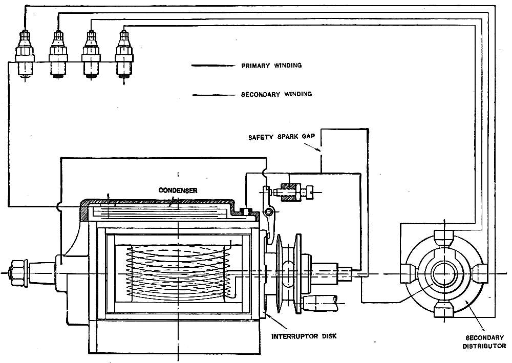
Fig. 14.—Wiring Diagram, Four-Spark Magneto.
The grounded end of the secondary winding is attached to the live end of the primary winding, and its other terminal passes to a contact point carried on a hard rubber disk placed on the revolving shaft immediately in front of the interruptor. The diagram shows a face view of this distributor, as well as a side view. A ring-shaped plate is set on one side of this disk, and is in connection with a contact piece carried on the edge of the disk. A [Pg 313]carbon brush to which the live end of the secondary winding is attached is kept pressed against the ring-shaped plate, and the secondary current is thus led to the contact piece on the edge of the disk. As the disk revolves with the shaft of the shield the contact piece comes into successive contact with four carbon brushes, which are connected to the spark plugs.
When the shield is in such a position that the lines of force flow through the neck of the armature, the interruptor is closed, but when the intensity of the current increases to the maximum the interruptor opens, breaking the primary circuit, and producing a rapid demagnetization of the armature core. This dying out of the field induces a powerful current in the secondary winding, which is led by the distributor to one of the spark plugs, where it jumps the gap and returns to the winding by the ground connection.
In setting the magneto the firing order of the engine is noted, as has been explained, and the magneto secured in position with its gear in mesh, but loose on the shaft. The cover over the space between the pole pieces will be found to be in the form[Pg 314] of a shallow aluminum box, which is held in position by a single screw with a large head, and when this is removed the stationary armature and revolving shield will be exposed to view. One of the pistons must then be brought into the position it will take with a fully advanced spark, and the shield then revolved until it is in the position shown in Fig. 15. The nut securing the gear to the shaft[Pg 315] may then be drawn up tight. It will be noticed that one of the segments of the shield has a deep notch at each edge. Remembering the direction in which the shield will be driven, the notch at the rear edge of the shield will indicate the position of the contact piece of the distributor which will then be coming into contact with the carbon brush of one of the stationary distributor contacts. The spark plug of the cylinder that is in the firing position should be connected to the brush that the notch indicates as making contact, and the remaining spark plugs and brushes connected according to the firing order.
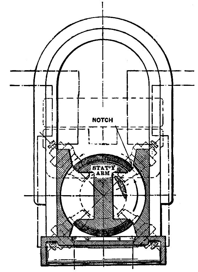
Fig. 15.—Timing Diagram, Four-Spark Magneto.
The proper operation of the magneto requires the free and perfect action of the interruptor, and this may be observed by means of a brass slide that operates on the arm or the spark control lever. When this slide is raised, the action of the interruptor may be watched. Like the two-spark Bosch magneto, the distance between these points when the disk separates them should be one sixty-fourth of an inch, and contact should be made and broken without undue sparking. The condenser that will be found in the shallow aluminum box covering the[Pg 316] space between the pole pieces prevents sparking at the interrupter, and is thrown into circuit automatically when it is placed in position.
The four-spark magneto is provided with a safety spark gap, and when the points of one of the spark plugs are separated too far, or when there is any interruption of the secondary circuit, a spark will show there. Sparks should not be permitted to pass in the safety gap for any considerable period, as damage will be done, and when they indicate by their presence that something is wrong, the trouble should be located and repaired without delay.
The regulation and care of the four-spark magneto is the same as has been described for the two-spark machine.
It has been the custom to equip jump-spark engines with two complete systems of ignition, one operated by a magneto and the other by coil and battery. Each system has its own spark plugs, timing device, wiring, etc., the two being connected only at the switch. Many of these duplicate parts have been eliminated by the introduction of dual ignition systems, and the mechanism is correspondingly simplified.[Pg 317] The Bosch dual system is a good example of the principles involved, and a diagram of the connections is shown on Fig. 16. The magneto used is of the usual two-spark type, except that the secondary current, instead of being led from the collecting ring direct to the distributer, is taken to the switch that is located in the coil box on the dash. In addition to the regulation interrupter illustrated on Fig. 11, the magneto is provided with a second interrupter or circuit breaker that controls the flow of the battery current, and takes the place of a timer. While the magneto interrupter revolves with the armature, and is operated by stationary cams, the battery circuit breaker is stationary, and is operated by a two-nose cam that revolves with the armature shaft. The stationary and revolving cams are so set that the interrupter and circuit breaker break their circuits at the same instant.
[Pg 318]
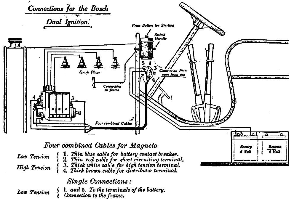
Fig. 16.—Bosch Jump-Spark Dual System.
The coil is contained in a brass case on the dash, and in design and construction is a duplicate of the magneto armature. Attached to the coil is a handle that projects through a slot in the case, by means of which the coil may be turned partly around in the case. The terminals of the coil windings are attached to metal knobs located on the under side of a fiber plate that forms the bottom of the coil, and [Pg 319]turning the coil by the handle moves these knobs in and out of contact with corresponding knobs on the bottom of the case. These knobs form the switch that cuts off all current, or permits the engine to be run on magneto or battery. When the switch is in such a position that the magneto produces secondary current, this flows from terminal 3 of the magneto to terminal 3 of the switch; thence by the switch connection to terminal 4 and to the secondary distributer. When the battery is switched in, the magneto primary is grounded, and secondary current from the coil flows over wire 4 to the secondary distributer.
By pressing a button on top of the coil case, a vibrator is cut into the circuit to permit starting the engine on the spark. When the engine starts the button is released, and ignition is produced by the single spark that results from the demagnetizing of the core that follows the breaking of the battery circuit by the circuit breaker. Throwing the switch breaks the battery circuit and cuts in the magneto.
[Pg 320]
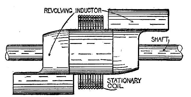
Fig. 17.—Remy Inductor.
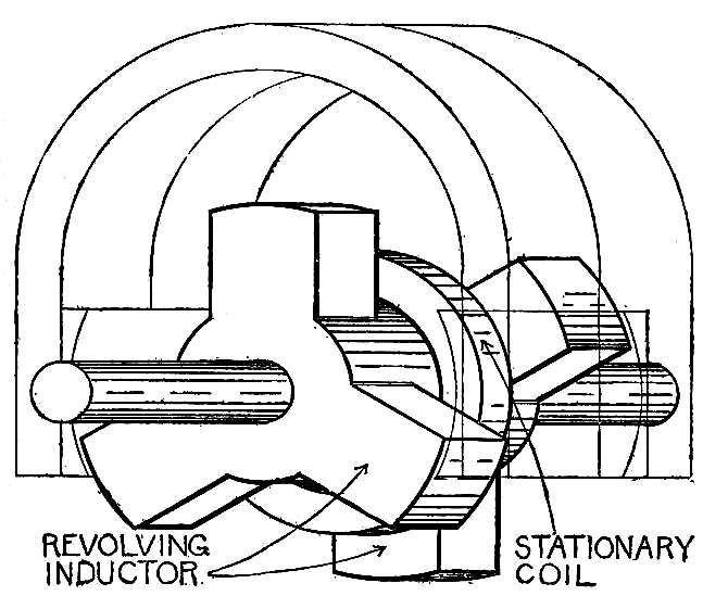
Fig. 18.—Inductor Giving Six Waves.
In types of magnetos that have recently been produced, the winding is stationary and surrounds a moving core that is magnetized and demagnetized during its revolution between the poles of the field magnets. The Remy magneto is of this type, and Fig. 17 is a diagram of the revolving core, or inductor, with the coil surrounding it. As the inductor revolves, the magnetism flows from one pole of the field magnets into the wing of the inductor nearest to it, through the central cylindrical part, and by the second wing to the other pole, the central part of the inductor then being magnetized. The magnetism of this portion dies away when the wings are in such a position that they bridge across from one pole to the other, but reappears when the central cylindrical part again becomes the only path by which the magnetism may flow. The constant changes in the magnetic strength of the central part affect the coil, and currents are induced in it. These currents, which are of low voltage, are led to the primary winding of a secondary induction coil similar to that used in the Eisemann system, the secondary current flowing to the plugs through a distributer located on the magneto. In the Remy system, the interrupter does not short circuit the magneto winding, as is the case with the Eisemann, but the flow of current is from the magneto winding to the grounded side of the interrupter, to the insulated [Pg 322]screw, to the primary winding of the coil, and back to the magneto. The interrupter is closed and the current flows in this circuit while the strength of the current is increasing, but when the current is at a maximum the interrupter breaks the circuit, the core of the coil loses its magnetism, and a secondary current is induced. The current reaches a maximum twice in each revolution.
In other magnetos, the form of the inductor is such that six or more waves of current are produced during each revolution. An inductor of this type is shown in Fig. 18. There are six arms radiating from the central cylindrical portion, three at each end, and equally spaced. The coil is usually made of flat copper ribbon instead of wire, and it surrounds the central cylindrical part between the two sets of arms. In the inductor shown, the magnetism of the central part will change strength six times to each revolution.
Magnetos of this type are used to replace batteries in jump spark systems using vibrator coils. They are driven by belt, or by friction against the fly wheel, and are given a speed at least three times that of the crank shaft. By this means the waves of current follow one another at such brief intervals that the flow is practically continuous, and it is[Pg 323] therefore unnecessary to time the magneto to the engine. These magnetos have no interrupters, and the wiring consists of one wire leading to the switch on the coil box, the usual connections between the coil box and timer, and a wire from the second magneto terminal to ground.
[Pg 324]
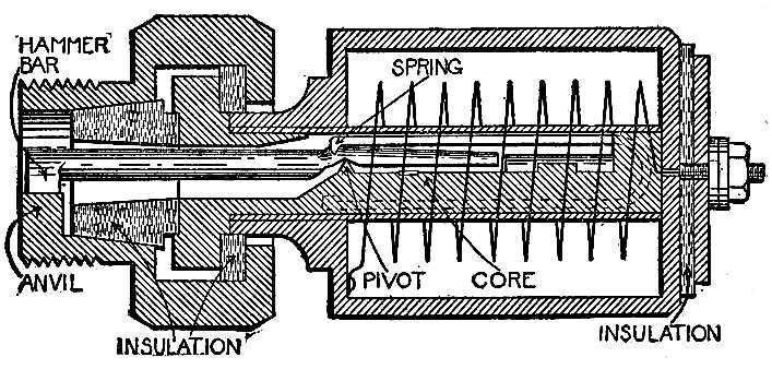
Fig. 19.—Magnetic Igniter.
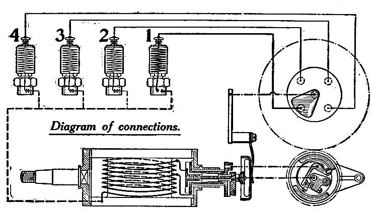
Fig. 20.—Wiring Diagram of Magnetic Igniter System.
The flaming spark produced by the make-and-break system has many advantages for ignition over the jump spark produced by the high-tension system, but these are largely offset by the mechanical complication of cams, tappets, springs, etc. A make-and-break system in which the igniters are operated by magnetism has been perfected by the Bosch company, and is giving good results. The magneto used is of the ordinary low-tension type, equipped with an interrupter, while all of the igniter parts are contained in a plug that screws into the cylinder wall like a jump-spark plug. The plug is shown in diagram in Fig. 19. The sleeve that screws into the cylinder supports an iron core, the two being thoroughly insulated by blocks and washers of heat-proof insulating material. The upper portion of the core has a flat side, on which is [Pg 325]formed a projection that serves as a pivot. A hammer bar is balanced on this pivot, its long end passing through the plug and coming into contact with an anvil attached to the screwed sleeve. A long horseshoe-shaped spring holds the two in light contact, and the hammer bar then forms the only path by which an electric current may pass from the core to the screwed sleeve and to the engine ground. When the hammer bar is moved on its pivot this connection is broken. Surrounding the core is a coil consisting of a few layers of wire covered with heat-proof insulation. The upper part of the plug is incased in a light iron casing screwed to the core, which completely incloses the core, hammer bar, spring and coil, and in which there is no opening that would permit the escape of compression from the combustion chamber. One terminal of the coil is connected to the binding post, and the other is grounded on the iron casing. The current generated in the magneto passes to a distributer and thence to the binding post of the plug, as shown in Fig. 20. It flows through the coil to the core, and thence by the hammer bar to the engine ground and back to the magneto. As the current establishes itself in the coil, the core becomes magnetized, and attracts to it the flat end of the hammer bar. When[Pg 326] the hammer bar moves on its pivot, its connection with the anvil is broken, and this break in the circuit produces a flaming spark that is in every way identical with the spark of the ordinary mechanical make-and-break igniter. The casing that contains the coil may be unscrewed from the core without disturbing the screwed sleeve, and this makes it an easy matter to give the moving parts the inspection and cleaning that they should receive every few weeks. The spark occurs in the plug at the instant that the interrupter operates, and the setting up of the system is identical with that of the high-tension magneto systems.
Arranged for the Scientific American
(Copyright, 1909, by Munn & Co.)
EFFECTS OF TROUBLE
| Engine will not start | Test Ignition and carbureter. | |
| Slow cranking or cold weather will interfere with the proper formation or the mixture. | ||
| Prime cylinders with gasoline in cold weather to obtain mixture for starting. | ||
| To increase suction in carbureter, prevent operation of air-valve. |
| Engine starts, but will not continue running. | Fuel does not flow freely to carbureter. | |
| Weak battery. |
| Explosions cease abruptly. | Break in ground wire, battery connections, switch lead. |
| Engine runs well slowly, but misses when speeded up. | Worn timer. | |
| Weak battery. | ||
| Faulty vibrator adjustment. | ||
| Faulty carbureter adjustment. | ||
| Fuel does not flow freely to carbureter. |
| Engine will not stop. | Preignition. | Glowing carbon or metal point in cylinder. | ||
| Engine too hot (see Cooling trouble). | ||||
| Engine does not deliver full power. | Faulty setting of valves. | |||
| Tight bearings or broken balls. | Indicated by excessive heating. | |||
| Back pressure. | Fouled muffler. | |||
| Dragging brakes. | ||||
| Friction in transmission. | ||||
| Faulty carburetion. | ||||
| Weak ignition. | ||||
| Weak compression. | ||||
| Overheating. | ||||
| Irregular miss. | Sticking valve. | |
| Slipping timer. | ||
| Loose half-time shaft. | ||
| Sticking air-valve. | ||
| Intermittent obstruction in spray nozzle. | ||
| Broken or weak valve-spring. | ||
| Loose connection. | ||
| Short circuit. |
| Engine noises. | Knocking. | Too much retard of spark. | ||
| Preignition. | ||||
| Worn bearings. | ||||
| Loose or cracked flywheel. | ||||
| Hissing. | Broken piston rings. | |||
| Leaking air inlet pipe or gasket. | ||||
| “Popping” in carbureter. | Leaking inlet valve. | |||
| Weak mixture. | ||||
| Excessive retard of spark. |
| Explosions weaken and cease. | Carbureter or fuel trouble. |
| Engine will not run slowly. | Weak magneto. | |
| Faulty carbureter adjustment. |
| Steady miss in one or more cylinders, (other cylinders firing normally). | Vibrator, timer, secondary circuit. |
| IGNITION. Jump spark, with single coil, battery secondary distributor. |
Test primary circuit as described for system using coils and timer. | |||||
| Secondary may short circuit from | Fouled or worn distributor. | |||||
| Defective insulation. | ||||||
| IGNITION. Jump spark, with battery, timer and coils. |
To test, revolve crank-shaft twice, listening for vibrators. | All vibrators sound normal, primary circuits O. K. unless timer has slipped on shaft. | Vibrator should begin to operate as a piston gets to top center of compression, with spark lever retarded. | |||||||||||
| One or more vibrators sound normal, showing that battery connections, lead and ground wires, and battery are O. K. | To test coils, short circuit the timer by making contact between primary terminal of coil and ground. | Vibrator normal, coil is O. K., look for | Interruption in timer circuit. | |||||||||||
| Blade moves, but will not vibrate. | Punctured condenser ([1]). | |||||||||||||
| Short circuit at vibrator. | ||||||||||||||
| Vibrator does not operate. | Faulty adjustment. | Too stiff. | Will operate only with strong battery. | |||||||||||
| Excessive sparking at vibrator, and battery exhausts rapidly. | ||||||||||||||
| Too weak. | Feeble secondary spark; misfiring with slightly corroded contacts. | |||||||||||||
| Contacts corroded. | ||||||||||||||
| Contacts stuck. | ||||||||||||||
| Vibrators do not operate. | Open switch; vibrator trouble. | |||||||||||||
| Trouble in battery or in primary circuit. | To test, make momentary contact from switch terminal to ground. | Bright spark, battery lead and ground wire O. K. | ||||||||||||
| Weak or no spark. | ||||||||||||||
| Break in battery connections, lead or ground wire. | ||||||||||||||
| Battery exhausted or dry cells polarized. | ||||||||||||||
| TEST 1. Alternate test, prime cylinders with a few drops of gasoline, close relief cocks, and crank. Explosions show ignition to be O. K. |
||||||||||||||
| To test secondary, disconnect spark plug leads, support them ⅜ inch from engine ground and crank. | Good spark, O. K. | |||||||||||||
| Weak spark. | ||||||||||||||
| No spark. | Vibrator trouble. | |||||||||||||
| Plug short circuited, fouled, oily. | ||||||||||||||
| Points too far apart—should be 1/32 inch. | ||||||||||||||
| Short circuit in secondary. | ||||||||||||||
| Broken condenser connection ([1]). | Shown by brilliant sparking at vibrator. | |||||||||||||
| IGNITION. Make and break, with low tension magneto. Use Test 1, cranking briskly. |
Explosions. | Ignition O.K. unless | Magneto is out of time and igniters incorrectly adjusted. | Should break circuit at top center of compression when spark is retarded. | ||||||||
| No explosions. | Short circuit. | Insulated bridge on magneto. | ||||||||||
| Switch or switch lead. | ||||||||||||
| Bus-bar or bus-bar lead. | ||||||||||||
| Igniter insulator broken. | ||||||||||||
| Igniter stuck closed. | ||||||||||||
| Broken spring. | ||||||||||||
| Tappet stuck in guide. | To test operate by hand. | |||||||||||
| Open circuit. | ||||||||||||
| Magneto broken down. | To test magneto, disconnect magneto lead from bus-bar and hold free end in bare fingers, or | Shock or spark. | Magneto O. K. | |||||||||
| TEST 2. Hold free end against teeth of metal gear and crank briskly. | No shock or spark. | Fouled collecting brush. | ||||||||||
| Armature burned out [1]. | ||||||||||||
| Fields demagnetized [1]. | To test, unmesh gear, revolve armature by hand. If fields are O. K., armature should turn perceptibly hard twice in each revolution. | |||||||||||
| CARBURETER. To test, hold lighted match over open relief cocks while engine is cranked briskly. |
Mixture ignites. | Proving that carbureter is doing its duty. | ||||||||
| Mixture does not ignite. Operate primer to flood float chamber. |
Gasoline drips from spray nozzle. | Mixture too rich. | Insufficient air. | Faulty adjustment of air valve. | ||||||
| Clogged inlet pipe. | ||||||||||
| Dust on inlet pipe screen. | ||||||||||
| Leaking float valve. | ||||||||||
| Float too heavy. | Soggy (if of cork) ([2]). | |||||||||
| Punctured (if of metal) ([3]). | ||||||||||
| Faulty adjustment of float. | ||||||||||
| Mixture too poor. | Too much air. | Faulty adjustment of air-valve. | ||||||||
| Leaks in inlet pipe. | ||||||||||
| Faulty adjustment of float. | ||||||||||
| Water in gasoline. | ||||||||||
| No drip from spray nozzle. | Clogged spray nozzle. | |||||||||
| Clogged float valve. | ||||||||||
| Clogged fuel feed. | ||||||||||
| No gasoline. | ||||||||||
| Empty tank. | ||||||||||
| Closed supply cock. | ||||||||||
| IGNITION. Jump spark with low tension magneto and coil (Eisemann, Remy, Splitdorf, etc.) |
Proceed as in Test 1, cranking briskly. | Explosions. | Ignition O. K. unless magneto is out of time. Should be reset. | |||||||||||
| Sparks in safety spark gap. | Interruption in secondary circuit. | |||||||||||||
| Too wide a gap at plugs (should be from 1/64 to 1/32 inch). | ||||||||||||||
| No explosions. | Primary circuit open. | |||||||||||||
| Primary short circuit. | ||||||||||||||
| Magneto broken down. | To test magneto, disconnect primary lead to coil and proceed as in test 2. | Shock (or spark), magneto O. K. | ||||||||||||
| No shock (or spark). | Interrupter short circuited, wet or oily. | |||||||||||||
| Field demagnetized ([1]). | ||||||||||||||
| Condenser broken down (shown by brilliant spark at interrupter) ([1]). | ||||||||||||||
| Coil broken down. | To test primary winding of coil disconnect ground wire and proceed as in second part of test 2. | Spark, winding O. K. | ||||||||||||
| No spark. | Winding broken ([1]) down or short or open circuited. | |||||||||||||
| To test secondary winding of coil, disconnect spark plug leads from magneto and crank briskly, watching for sparks at safety spark gap. | Sparks, look for | Plugs short circuited. | Fouled. | |||||||||||
| Insulation broken down. | ||||||||||||||
| Fused metal bead at points. | ||||||||||||||
| Secondary short circuit ([1]). | Leads short circuited. | |||||||||||||
| Ground circuit open. | ||||||||||||||
| No sparks, winding broken down. | ||||||||||||||
| IGNITION. High tension magneto (Bosch, U. & H. Lacoste, Witherbee, etc. |
Proceed as in Test 1, cranking briskly. | Explosions. | Ignition O. K. unless magneto is out of time. Should be reset. | |||||||||||
| Sparks in safety spark gap. | Break in secondary circuit. | |||||||||||||
| Too wide a gap at plugs (should be from 1/64 to 1/32 inch). | ||||||||||||||
| No explosions. | To test magneto, disconnect spark plug leads from distributor and crank briskly, watching for sparks at safety spark gap. | Sparks. | Magneto O. K. | |||||||||||
| Look for short circuits in | Spark plugs. | Fouled. | ||||||||||||
| Insulation broken down. | ||||||||||||||
| Bead of fused metal between points. | ||||||||||||||
| Switch lead. | ||||||||||||||
| Switch. | ||||||||||||||
| No sparks. | Corroded interrupter contacts. | |||||||||||||
| Interrupter stuck. | ||||||||||||||
| Armature burned out ([1]). | ||||||||||||||
| Condenser broken down ([1]). | ||||||||||||||
| Field demagnetized ([1]). | ||||||||||||||
| FUEL FEED SYSTEM. | To test, open drain cock at carbureter. | Gasoline flows. | System is O. K. | |||||||
| Gasoline does not flow. | Gravity feed. | Clogged vent hole in filling cap. | ||||||||
| Clogged piping ([4]). | ||||||||||
| Pressure feed. | Sufficient pressure in tank. | Clogged piping ([4]). | ||||||||
| Insufficient pressure in tank. | ||||||||||
| Leaking tank or piping. | ||||||||||
| Leaking filling cap. | ||||||||||
| Stuck relief valve. | ||||||||||
| COMPRESSION. | To test, crank engine slowly, noting resistance, which should be the same in all cylinders. (Do not confuse constant mechanical resistance with intermittent resistance of compression). Inject oil into faulty cylinder. |
Improved compression indicates | Stuck piston rings. | Douse cylinder with kerosene and alcohol ½ and ½ to cut carbon. | ||||||
| Worn or scored piston rings. | ||||||||||
| Scored cylinder walls. | ||||||||||
| No improvement in compression indicates | Worn or pitted valves. | |||||||||
| Leaking spark plug, igniter plate, relief cock, etc. | Test by running oil around these and cranking. | Leak indicated by bubbles. | ||||||||
| Piston ring splits in line. | ||||||||||
| Broken piston rings. | Crank case will be abnormally warm. | |||||||||
| Cracked walls or head. | Indicated by water in cylinder. | |||||||||
| Sticking valves. | ||||||||||
| Insufficient space between valve stem and push rod. | ||||||||||
| COOLING. (Water.) |
Radiator should heat evenly shortly after engine is started. | Radiator does not heat. | Clogged circulation system. | Empty tank. | ||||||
| Clogged piping. | ||||||||||
| Defective pump. | ||||||||||
| Test by opening pet cocks. | ||||||||||
| Radiator steams. | Failure of lubrication. | Indicated by groans from cylinders affected. | Supply should be just sufficient to produce faint whiff of blue smoke at exhaust. | |||||||
| Defect in circulation. | ||||||||||
| Too much running on retarded spark or on low speed. | ||||||||||
| Slipping fan drive. | ||||||||||
* It is taken for granted that the engine is capable of running properly, that the tanks are filled, and that the switch is correctly thrown.
[1] Return to makers for repair.
[2] Dry in oven, and coat with shellac.
[3] Plunge in hot water to expel gasoline and to locate leak. Repair with solder.
[4] May be cleared with blast from foot pump.
[Pg 327]
THE END
A MOTOR-BOAT STORY.
Across Europe in a Motor-Boat.
By Henry C. Rowland, author of “In the Shadow,” etc. Illustrated by upward of fifty sketches. 12mo. Decorated cloth, gilt top, $2.00 net.
This is a delightful narrative of an absolutely unique trip. Mr. Rowland and his two friends had a motor-boat constructed in London for a seven-thousand-mile inland voyage which should circle Europe by way of the Seine, the Rhine, the Danube, and the Black Sea. The struggles with the motor, which develops a degree of perversity almost human, the innumerable humorous and exciting incidents, and the final terrific adventure which ends the narrative with a shipwreck in the Black Sea, make it the most novel and entertaining book of travel of recent years. The talented author is well known through half a dozen books and many magazine stories. The style of the volume is very attractive. Some fifty sketches are sprinkled through the text.
D. APPLETON AND COMPANY, NEW YORK.
AN EXTRAORDINARY BOOK.
The Unofficial Letters of an Official’s Wife.
By Edith Moses. 12mo. Cloth, gilt top, $1.50 net.
This is a volume of actual letters which Mrs. Moses, the wife of Professor Moses, wrote from the Philippines to her relatives here in the United States. Professor Moses, who is connected with the University of California, was one of the five members of the first commission, of which Secretary Taft was the head, sent out by the U. S. Government to organize the government of the Philippine Islands. The members of this commission were practically the first important Americans to go to the Philippines in a peaceful and a civil capacity. Mrs. Moses, therefore, saw the social, political, and home life in Manila as well as in the provinces and the different islands before American civilization had entered there to any extent. Her letters, while descriptive, have a very definite connection one with the other. They describe the arrival at the Philippines, the beginning of life there, housekeeping, the seemingly strange methods of daily life, servant problems, and so on, in Manila. Nothing like these letters has appeared in regard to the Philippine Islands at any time. It should be borne in mind, furthermore, that these letters are not in any way technical or having to do with the organization of the Philippine government. They are, as the title suggests, quite “unofficial” letters of a lady who, because of her connection with official circles, saw many things which an ordinary traveler never could see.
D. APPLETON AND COMPANY, NEW YORK.