
Title: The boy mechanic, book 3
800 things for boys to do
Editor: H. H. Windsor
Release date: October 12, 2023 [eBook #71856]
Most recently updated: September 20, 2025
Language: English
Original publication: Chicago: Popular Mechanics Co, 1919
Credits: Charlene Taylor, Harry Lamé and the Online Distributed Proofreading Team at https://www.pgdp.net (This file was produced from images generously made available by The Internet Archive/American Libraries.)
Please see the Transcriber’s Notes at the end of this text.
New original cover art included with this eBook is granted to the public domain.

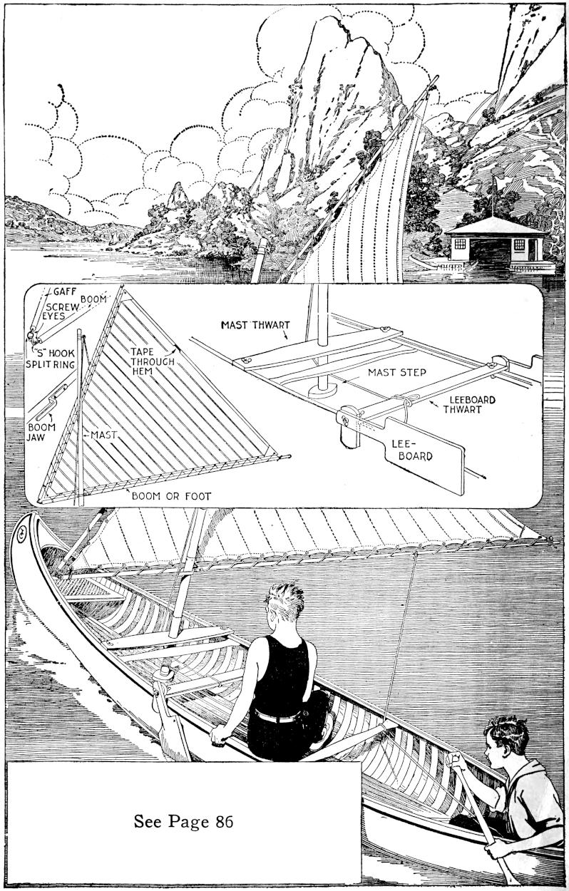
See Page 86
The
Boy Mechanic
BOOK 3
800 THINGS FOR BOYS TO DO
HOW TO CONSTRUCT
ELECTRIC LOCOMOTIVE MODEL AND TRACK SYSTEM, BOYS’ MOTOR
CAR, PARCEL DELIVERY BICYCLE, AERIAL CABLEWAY, MINIA-
TURE TANK, SAILING CANOE, HOUSEBOAT, SUBMARINE
CAMERA, DIVING TOWER, HAMMOCKS, KITCHEN
FOR HIKERS, ICE YACHT
AND
HUNDREDS OF OTHER THINGS WHICH DELIGHT EVERY BOY
WITH 802 ILLUSTRATIONS
COPYRIGHTED, 1919, BY H. H. WINDSOR
CHICAGO
POPULAR MECHANICS CO.
PUBLISHERS
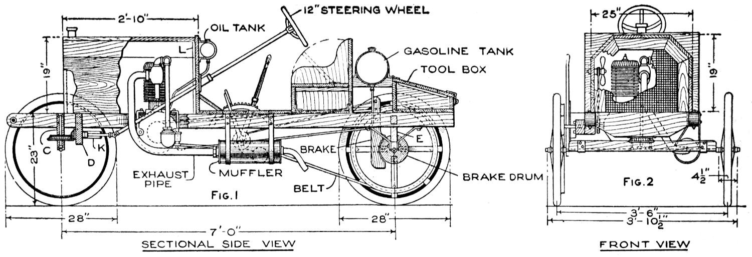

| Fig. 1 SECTIONAL SIDE VIEW |
Fig. 2 FRONT VIEW |
|
| Fig. 3 PLAN |
Fig. 4 BRAKE DETAIL |
|
| Fig. 5 DETAIL OF STEERING GEAR |
DETAIL OF SUPPORT C | |
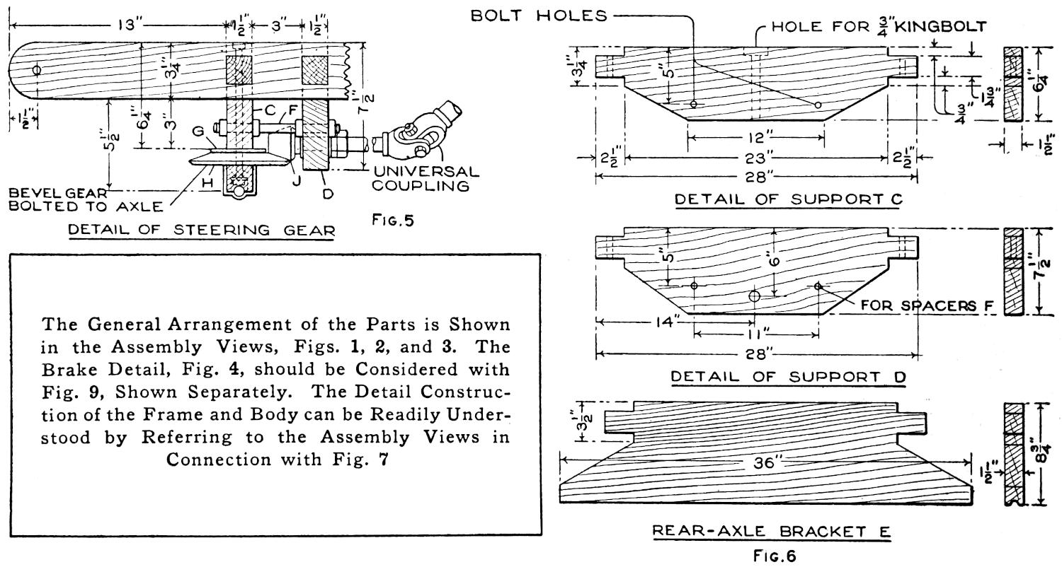
| The General Arrangement of the Parts is Shown in the Assembly Views, Figs. 1, 2, and 3. The Brake Detail, Fig. 4, should be Considered with Fig. 9, Shown Separately. The Detail Construction of the Frame and Body can be Readily Understood by Referring to the Assembly Views in Connection with Fig. 7 | DETAIL OF SUPPORT D | |
| REAR-AXLE BRACKET E Fig. 6 |
||
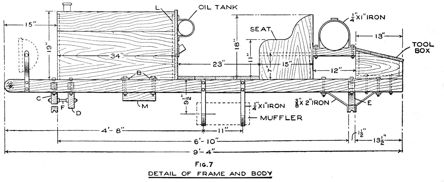
| Fig. 7 DETAIL OF FRAME AND BODY |
||
[1]

A Boys’ Motor Car
HOMEMADE
by P.P. Avery
Even though the home-built “bearcat” roadster, or other favorite model, does not compare in every detail with the luxurious manufactured cars, it has an individuality that puts it in a class by itself. The amateur mechanic, or the ambitious boy, who is fairly skilled with tools, can build at least the main parts for his own small car, of the simple, practical design shown in the sketch and detailed in the working drawings. If necessary, he can call more skilled mechanics to his aid. A motorcycle engine, or other small gasoline motor, is used for the power plant. The control mechanism of the engine and the electrical connections are similar to those of a motorcycle. They are installed to be controlled handily from the driver’s seat. The car is built without springs, but these may be included, if desired, or the necessary comfort provided—in part at least—by a cushioned seat. Strong bicycle wheels are used, the 1¹⁄₂ by 28-in. size being suitable. The hood may be of wood, or of sheet metal, built over a frame of strap iron. The top of the hood can be lifted off, and the entire hood can also be removed, when repairs are to be made. The tool box on the rear of the frame can be replaced by a larger compartment, or rack, for transporting loads, or an extra seat for a passenger.
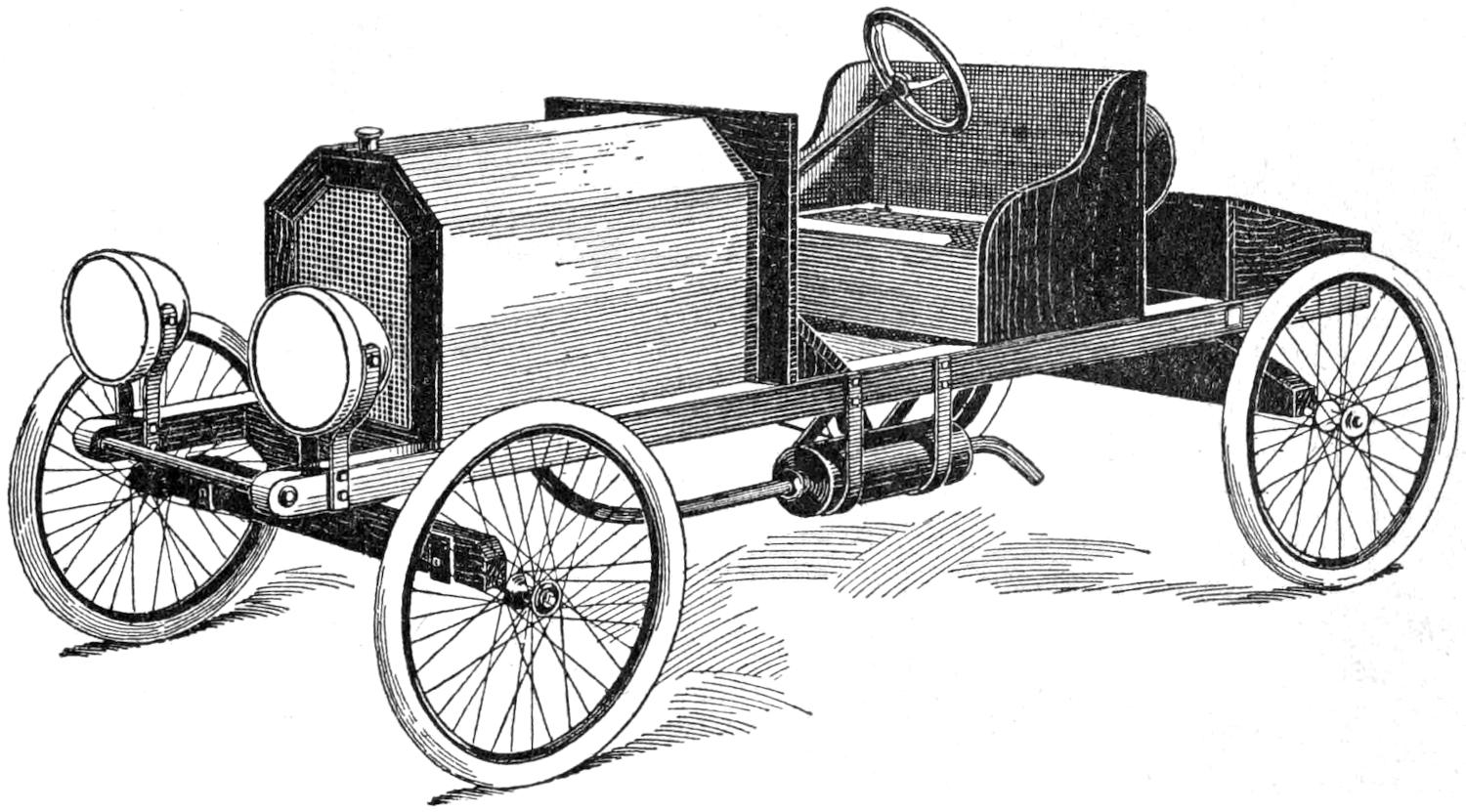
To Simplify This Small but Serviceable Motor Car for Construction by the Young Mechanic, Only the Essential Parts are Considered. Other Useful and Ornamental Features may be Added as the Skill and Means of the Builder Make Possible
The construction may be begun with the chassis and the running gear. Fit the wheels with ⁵⁄₈-in. axles, as shown in the assembly views, Figs. 1, 2, and 3, and detailed in Fig. 4. Fit the ends of the axles to the hubs of the wheels, providing the threaded ends with lock nuts. Make the wooden supports for the frame, as detailed in Fig. 6. The axles are fastened into half-round grooves, cut in the bottoms of the supports, and secured by iron straps, as shown in Fig. 4, at A. Make the sidepieces for the main frame 2¹⁄₂ by 3¹⁄₄ in. thick, and 9 ft. 4 in. long, as detailed in Fig. 7. Mortise the supports through the sidepieces, and bore the holes for the bolt fastenings and braces. Glue the mortise-and-tenon joints before the bolts are finally secured. Provide the bolts with washers, and lock the nuts with additional jam nuts where needed. Keep the woodwork clean, and apply a coat of linseed oil, so that dirt and grease cannot penetrate readily.
Finish only the supporting structure of the chassis in the preliminary woodwork. Set the front-axle and steering-rigging supports C and D, and adjust the spacers F between them. Bore the hole for the kingbolt, as detailed in Fig. 6, and fit the bevel gears and the fifth wheel G, of ¹⁄₄-in. steel, into place, as shown in Fig. 5. The gear H is bolted to the axle support. The[2] pinion J is set on the end of a short ³⁄₄-in. shaft. The latter passes through the support D, and is fitted with washers and jam nuts, solidly, yet with sufficient play. A bracket, K, of ¹⁄₄ by 1³⁄₄-in. strap iron, braces the shaft, as shown in Fig. 3. The end of this short shaft is joined to one section of the universal coupling, as shown, and, like the other half of the coupling, is pinned with a ³⁄₁₆-in. riveted pin. The pinion is also pinned, and the lower end of the kingbolt provided with a washer and nut, guarded by a cotter pin. Suitable gears can be procured from old machinery. A satisfactory set was obtained from an old differential of a well-known small car.
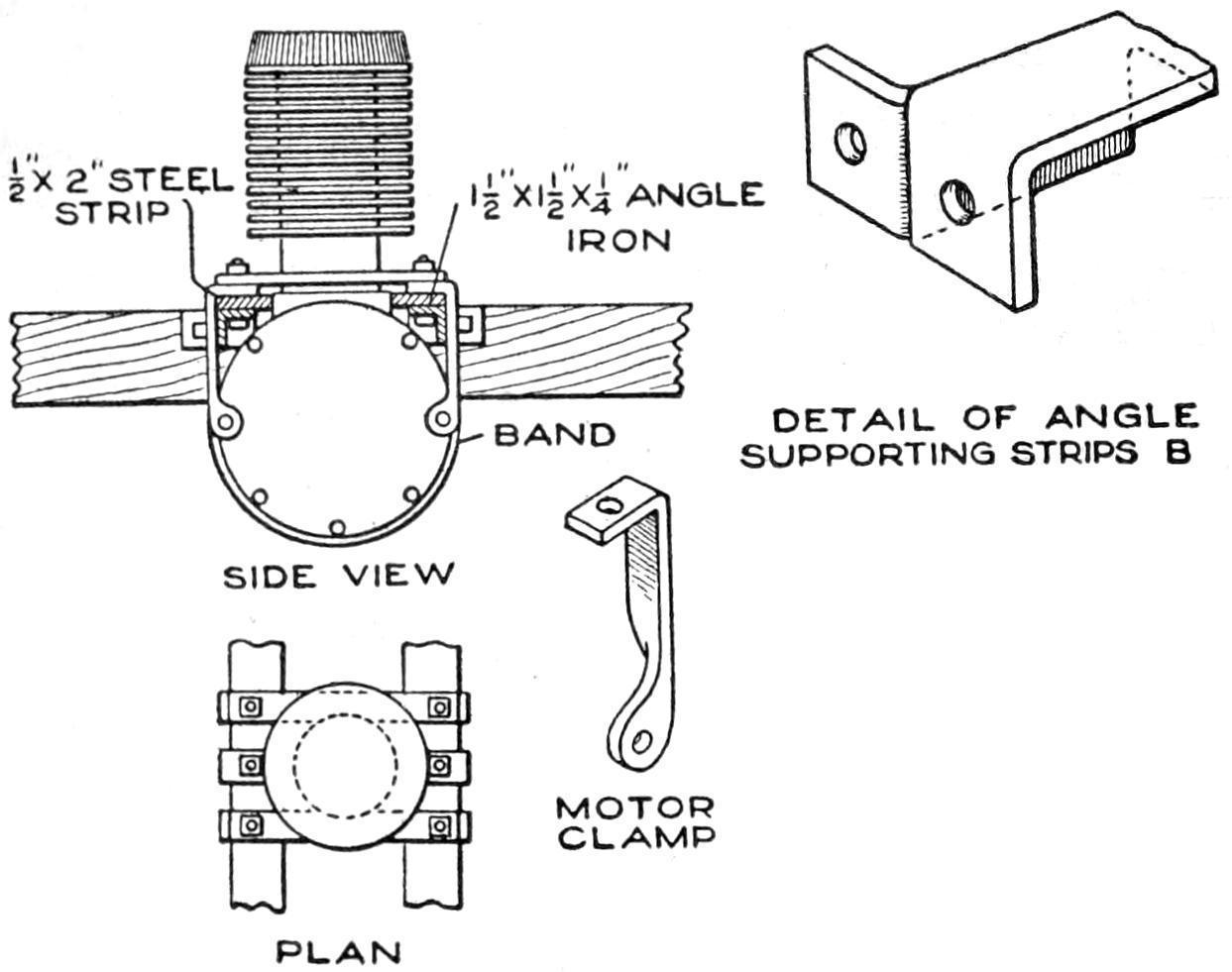
Fig. 8
Detail of the Motor
Support: The Engine
is Mounted on
Reinforced Angle
Irons, and Secured
by Clamps and a
Supporting Band
under the Crank
Case
Before fitting the steering column into place, make the dashboard, of ⁷⁄₈-in. oak, as shown in the assembly view, and in detail in Fig. 7. It is 19¹⁄₂ in. high and 2 ft. 4 in. wide, and set on the frame and braced to it with 4 by 4 by 1¹⁄₂-in. angle irons, ¹⁄₄ in. thick. Fit a ⁷⁄₈-in. strip of wood around the edge of the dashboard, on the front side, as a rest for the hood, as shown in Figs. 1 and 7, at L. A brass edging protects the dashboard, and gives a neat appearance. Lay out carefully the angle for the steering column, which is of ⁷⁄₈-in. shafting, so as to be convenient for the driver. Mark the point at which it is to pass through the dashboard, and reinforce the hole with an oak block, or an angle flange, of iron or brass, such as is used on railings, or boat fittings. A collar at the flange counteracts the downward pressure on the steering post. The 12-in. steering wheel is set on the column by a riveted pin.
The fitting of the engine may next be undertaken. The exact position and method of setting the engine on the frame will depend on the size and type. It should be placed as near the center as possible, to give proper balance. The drawings show a common air-cooled motor of the one-cylinder type. It is supported, as shown in Figs. 1 and 3 and detailed in Fig. 8. Two iron strips, B, riveted to 1¹⁄₂ by 1¹⁄₂-in. angle irons, extend across the main frame, and support the engine by means of bolts and steel clamps, designed to suit the engine. Cross strips of iron steady the engine, and the clamps are bolted to the crank case. The center clamp is a band that passes under the crank case.
The engine is set so that the crankshaft extends across the main frame. Other methods may be devised for special motors, and the power transmission changed correspondingly. One end of the crankshaft is extended beyond the right side of the frame, as shown in Fig. 3. This extension is connected to the shaft by means of an ordinary setscrew collar coupling. A block M, Figs. 3 and 7, is bolted to the frame, and a section of heavy brass pipe fitted as a bearing.
The ignition and oiling systems, carburetor, and other details of the engine control and allied mechanism, are the same as those used on the motorcycle engine originally, fitted up as required. The oil tank is made of a strong can, mounted on the dashboard, as shown in Figs. 1 and 2. It is connected with the crank case by copper tubing. A cut-out switch for the ignition system is mounted on the dashboard. The controls used for the engine of the motorcycle can be extended with light iron rods, and the control handles mounted on the dashboard or in other convenient position. The throttle can be mounted on the steering column by fitting an iron pipe around the post and mounting this[3] pipe in the angle flange at the dashboard. A foot accelerator may also be used, suitable mountings and pedal connections being installed at the floor.
In setting the gasoline tank, make only as much of the body woodwork as is necessary to support it, as shown in Figs. 1, 3, and 7. The tank may be made of a can, properly fitted, and heavy enough, as determined by comparison with gasoline tanks in commercial cars. The feed is through a copper tube, as shown in Fig. 1. A small venthole, to guard against a vacuum in the tank, should be made in the cap. The muffler from a motorcycle is used, fitted with a longer pipe, and suspended from the side of the frame.
The transmission of the power from the motor shaft to the right rear wheel is accomplished by means of a leather motorcycle belt, made by fitting leather washers close together over a bicycle chain, oiling the washers with neat’s-foot oil. A grooved iron pulley is fitted on the end of the motor shaft, and a grooved pulley rim on the rear wheel, as shown in Figs. 1 and 3, and detailed in Fig. 4. The motor is started by means of a crank, and the belt drawn up gradually, by the action of a clutch lever and its idler, detailed in Fig. 9. The clutch lever is forged, as shown, and fitted with a ratchet lever, N, and ratchet quadrant, O. The idler holds the belt to the tension desired, giving considerable flexibility of speed.
The brake is shown in Figs. 1 and 3, and detailed in Figs. 4 and 9. The fittings on the rear wheel and axle are made of wood, and bolted, with a tension spring, as shown. The brake drum is supported on iron bands, riveted to the wheel, and to the pulley rim. The brake arm is connected to the brake wheel by a flexible wire. When the pedal is forced down, the wire is wound on the brake wheel, thus permitting of adjustment. The pedal is of iron and fixed on its shaft with a setscrew. An iron pipe is used as a casing for the central shaft, the shaft carrying the clutch lever, and the pipe carrying the brake pedal and the brake wheel. The quadrant O is mounted on a block, fastened to the main frame. The central shaft is carried in wooden blocks, with iron caps. A catch of strap iron can be fitted on the floor, to engage the pedal, and lock the brake when desired.
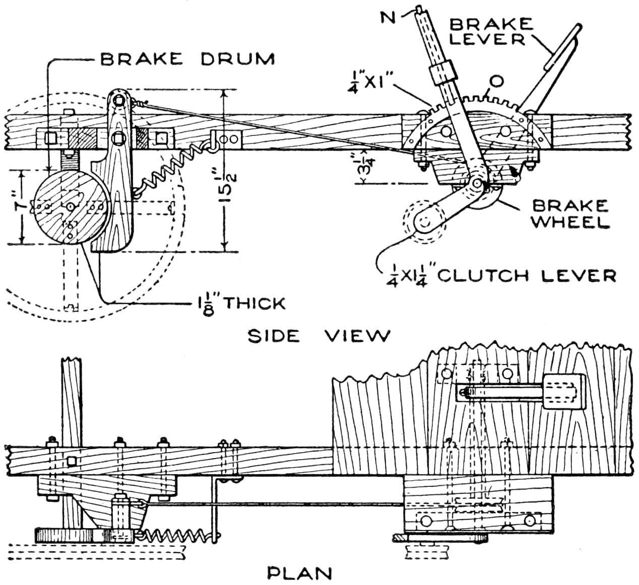
DETAIL OF BRAKE AND CLUTCH LEVER
Fig. 9
The Brake is Controlled by a Pedal, and a Clutch Lever is Mounted on the Central Shaft, and Set by Means of a Ratchet Device and Grip-Release Rod
The engine is cooled by the draft through the wire-mesh opening in the front of the hood, and through the openings under the hood. If desirable, a wooden split pulley, with grooved rim and rope belt, may be fitted on the extension of the engine shaft, and connected with a two-blade metal fan, as shown in Fig. 2.
The lighting arrangement may next be installed, gas or electric lamps, run on batteries, being used. Mudguards are desirable if the car is to be used on muddy roads. Strong bicycle mudguards can be installed, the guard braces being bolted on the axles. A strong pipe, with a drawbolt passing through its length, is mounted across the front of the frame. The body is built of ⁷⁄₈-in. stock, preferably white wood, and is 2 ft. 4 in. wide. A priming coat should be applied to the woodwork, followed by two coats of the body color, and one or two coats of varnish. The metal parts, except at the working surfaces, may be painted, or enameled.
[4]
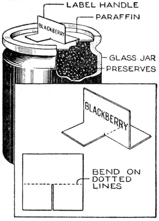
A neat and convenient method of making a label for jars of preserves, or similar preparations, to serve as a tab for removing the cover of paraffin on the glass, or dish, is shown in the sketch. The tabs are cut from tag board, notched, as shown, and bent on the dotted line. When melted paraffin is poured on top of the material in the jar, the tab is imbedded in it. To remove the paraffin cover intact, a pointed knife is run around the edge, or the glass warmed sufficiently to loosen the cover, which is then easily removed.—Arthur M. Cranford, St. Louis, Mo.
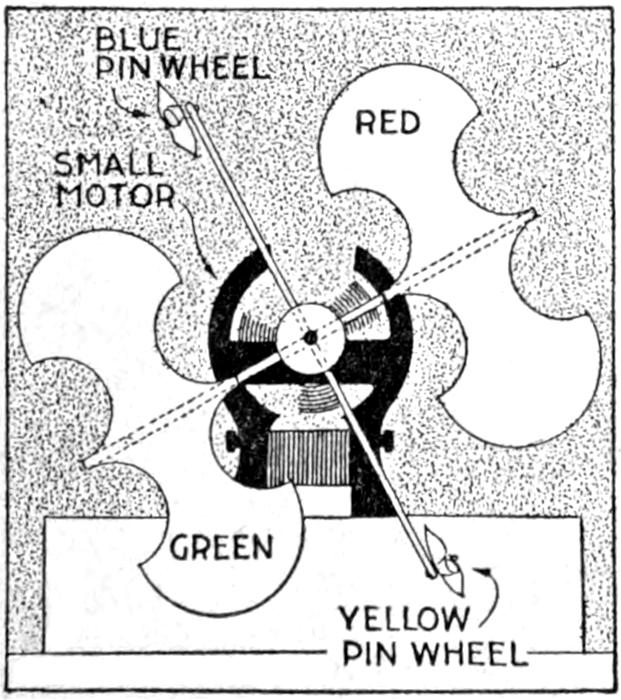
A contrivance that keeps the baby entertained, by the hour, at intervals, and is a big help to a busy mother, was made in a short time. I mounted four wooden arms on a small motor, as shown. On the ends of two of the arms, I fixed small pin wheels, one blue and the other yellow. The other arms hold curious-shaped pieces of bright cardboard, one red and the other green. The driving motor is run by one two-volt cell. The revolving colored pin wheels amuse baby in his high chair, and the device has well repaid the little trouble of making it.—A. H. Lange, St. Paul, Minn.
A simple method of providing a homemade locking device for a tier of drawers, the use of only one keyed lock being necessary, as is common in manufactured cases, is shown in the sketch. This is applicable to new or old cases, where a space of about 1¹⁄₂ in. is available between the back of the drawers and the rear of the case.
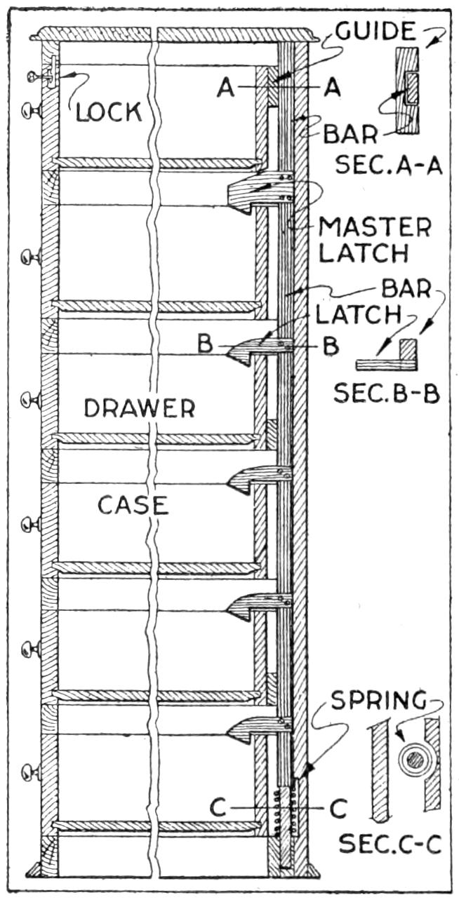
The device, as detailed, consists of a locking bar sliding in guides, screwed or fastened to the back of the case. Attached to the bar are latches one less in number than there are drawers, and spaced apart the distance that each drawer top is above the one below. The upper latch is the master feature. The top of this is beveled off, forcing it downward when the top drawer is closed. The locking bar, with the other latches, also moves down, and the latch fingers engage the backs of the drawers. The connecting bar is operated by a light coil spring, set on a shouldered rod at the bottom of the bar, as detailed.
The master latch may be attached at any place on the bar, and should be placed at the bottom drawer, for cases too high to be reached handily. To make the device for a small space, a ¹⁄₄-in. metal rod, with metal fingers clamped on, can be used. Metal striking plates are then put on the back edges of the drawers.—G. A. Luers, Washington, D. C.
¶Steam-pipe drains should be provided at all points in the line where water is likely to accumulate.
[5]
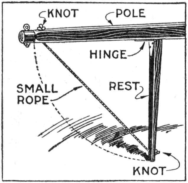
To do away with the annoyance and strain of holding up the heavy pole of a mowing machine while fastening the yoke strap to the hames of a restless team of horses, I equipped the pole with a drop stick, or rest. This was made of a 30-in. piece of an old carriage shaft. One end of the rod was hinged to the underside of the pole as shown. When the machine is in operation, the stick is tied up out of the way by means of a rope. This appliance also lengthens the life of the pole, and can be used on various kinds of vehicles.—T. H. Linthicum, Annapolis, Maryland.
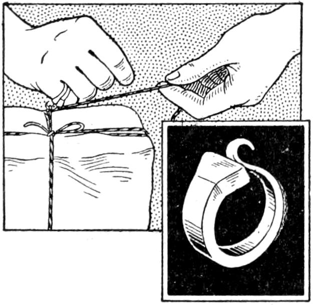
Persons having to tie a large number of packages or parcels soon find that their fingers become sore from breaking the heavy cord in the usual manner by wrapping it around the finger to form a cutting loop. A handy device, that can easily be made, is a string-cutting ring fashioned from a horseshoe nail, as shown. The point of the nail is curled into a hook, and the inner edge of the hook is sharpened. The string is quickly looped around the hook and cut by a slight pull on the free end. The ring is worn on the little finger.—C. C. Spreen, Flint, Mich.
¶A block of soft rubber, 1¹⁄₂ by 3 by 5 in., is useful as a pad for sandpaper in smoothing curved surfaces.
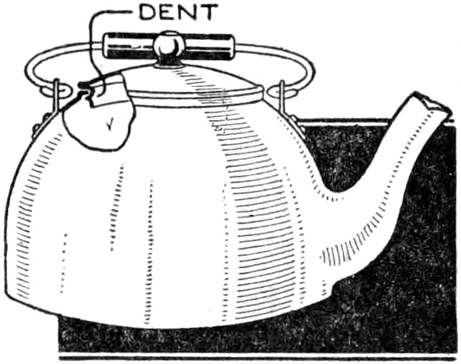
To prevent kettle covers from dropping off, and the fingers from being burned by the escaping steam, make a small dent in the edge of the lid, as shown. In setting the lid into place, arrange it so that the dent is at the point opposite the spout. Thus, when the water is poured from the kettle, the lid cannot easily tip forward.—W. J. Parks, LaSalle, Ill.
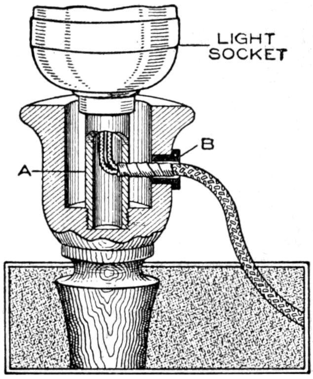
A number of wooden candlesticks were to be fitted with fixtures for electric lights, and it was found that the types ordinarily available could not be attached in the usual manner. A simple method was, therefore, devised, as shown in the sketch, and proved practical. A short length of brass tubing, A, was screwed into a hole drilled in the bottom of the candle socket, both ends of the tube being threaded. A hole was drilled through the side of the tube, and another through the side of the candlestick cup, as indicated. The hole in the wood was fitted with an insulation ring, B. The wiring, suitably taped, was carried through the opening for it, into the tube, and fastened in the usual manner to a standard keyless socket, which was then screwed to the end of the tube, making a substantial support. The lights were controlled conveniently at the usual wall switches.—Livingston Haviland, Buffalo, N. Y.
[6]
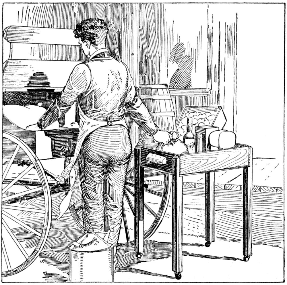
The Parcels are Handled Easily and with Little Danger of Damage by the Use of This Homemade Carrier
Instead of carrying out an armload, or a boxful, of miscellaneous parcels to the delivery wagon or the customer’s vehicle, an enterprising grocery clerk made a parcel carrier fitted with casters, as shown in the sketch. An ordinary wooden box was used for the tray, and handles were fitted at the ends. The legs were made of light strips nailed as shown. The parcels are loaded into the tray and the arrangement carried or rolled along on the casters, as is convenient. Besides making the work of handling the articles easier, they are kept clean, since it is not necessary to lay them on the walk or other undesirable place.—Avis Gordon Vestal, Chicago, Ill.
Irregularities in the feeding of the paper into a typewriter are often due to slippery spots on the platen. To overcome this trouble, clean the platen thoroughly with a mixture of two parts of denatured alcohol to one part of ether. Rub the polished parts with No. 2 emery cloth, then smooth the surface with No. 0 emery cloth. In cleaning a typewriter with gasoline, the effect is to leave the parts dry. A better method is to use a mixture of one part of typewriter oil to 50 parts gasoline. This will leave a fine coating of oil, which is too fine to collect dust, on the working parts.—William Doenges, Fort Sam Houston, Texas.
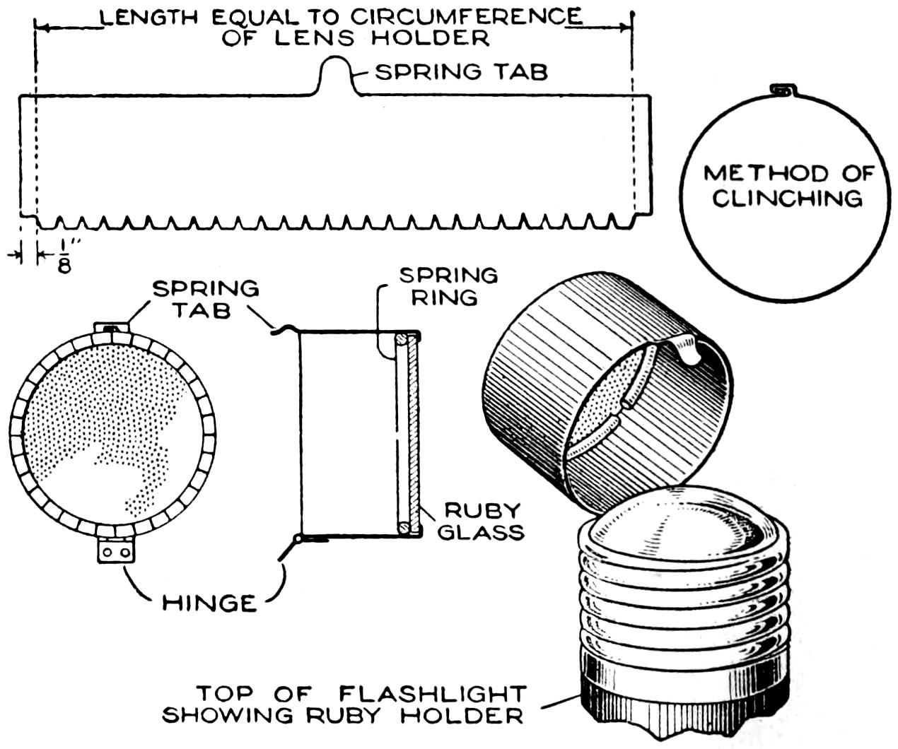
A Ruby Cap Hinged over the Lens of an Ordinary Flash Light Is a Convenience for the Dark Room
Amateur photographers will find a red lens attachment for a hand flash light a useful arrangement for the dark room, when going in or out, and during the process of developing, especially in temporary quarters. To fit the device in place, measure the distance around the outside of the lens holder, and lay out this dimension on a strip of tin, or other metal, 1 in. wide, as shown. Then add ¹⁄₈ in. at each end, and an extra strip, which should be cut into ¹⁄₄-in. sections, along the whole length. A spring tab, midway along the top edge of the metal, is also made. Curl the piece to a cylindrical form and clinch the joint as detailed, and bend the notched tabs into place. Slip a piece of ruby glass into the cylinder and hold it against the notched tabs with a spring ring. Then solder a small hinge to the edge of the cylinder and to the lens holder on the flash light, so that the spring tab will snap into place. When a white light is wanted, the red-glass fitting is released, as shown.
[7]
The home craftsman who is fairly skilled with woodworking hand tools will be well repaid for a little extra care in making this mission center table, of unusual design. Most of the woodwork involved in its construction is quite simple, the element calling for careful work being the laying out and shaping of the octagonal top and the shelf. Because of the wide surfaces exposed it will also pay the maker to plane, scrape, and sand down these surfaces carefully. By selecting the best pieces of wood and setting their better sides out, the effect is also enhanced. The table can be finished in a variety of ways to suit the furniture of the room where it is used. Various kinds of hard wood are suitable, quarter-sawed oak being preferable.
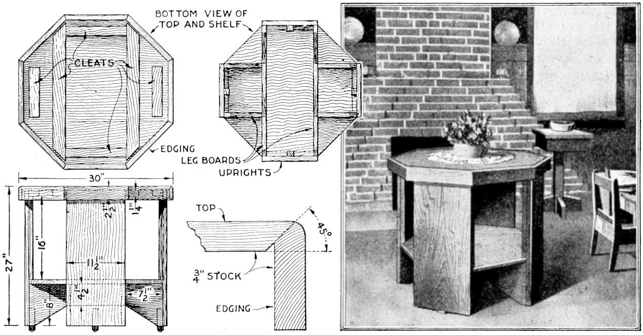
The Home Craftsman will Find the Making of This Octagonal Mission Center Table a Novel Piece of Construction. It Offers No Special Difficulties if Care is Taken in the Shaping of the Top and Shelf
Begin the construction by gluing up the pieces for the top and the shelf. While they are drying, make the pieces for the legs, the lower braces, and the strips for the edging of the top. The upper portion of the legs is of double thickness, ⁷⁄₈-in. stock being used throughout. Fit the lower supporting framework together as shown in the bottom view of the shelf, two of the braces extending across the bottom and the others butting against them.
When the top and shelf are dry, brace the top with cleats screwed on underneath, as shown in the bottom view of the top. Lay out the shelf accurately, and shape it to a perfect octagon, 25 in. across from opposite parallel sides. Make a strip, 1⁵⁄₈ in. wide, and use it in marking the layout for the top, from the shelf as a pattern, the edges of the top being parallel with those of the shelf and 1⁵⁄₈ in. from them.
Assemble the parts as shown, using glue and screws where practicable, and properly set nails for places where the fastening will be exposed. All the stock should be cleaned up thoroughly both before and after assembling. Four pieces for the casters are fastened to the legs with screws. The edging for the top may be mitered, with a rounded corner, as shown in the detail, or butted square against the edge of the top, as indicated in the photograph and the plan of the top, the latter method being far easier.
¶The nuisance of tracking dust and ashes from the basement can be overcome, to a considerable extent, by providing carpet mats on two or three lower treads of the stairs leading from the basement to the rooms above.
[8]
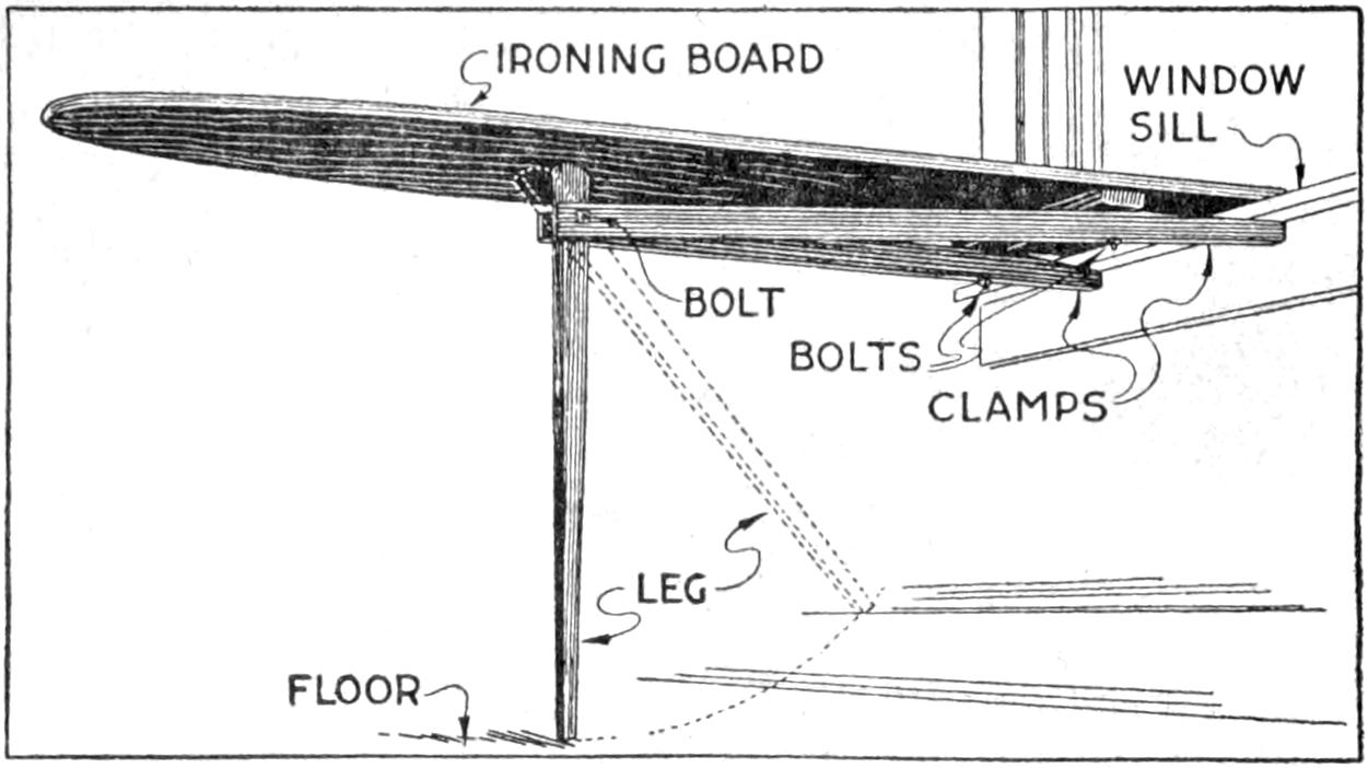
This Rigid Ironing Board Folds Compactly and can be Set Up with Ease at the Window Sill
An ironing board is usually most convenient for use when its left end is set near a window, or other source of light. The arrangement shown in the sketch was designed with this in mind, and other interesting features were added. The top is of the usual type. Arranged underneath it is a cross cleat near one end. Bolted through this are two clamps which engage the edge of the window sill or table. They are clamped by lowering the leg from its folded position, underneath the top, as indicated. The bolts at the clamps are adjustable for gripping various thicknesses of table tops, etc., between the clamps and the top. The lower end of the leg can be fitted with a sliding adjustment, if the board is used at different heights, the design being otherwise the same.—T. J. Hubbard, Mendota, Ill.
A desirable vine often has not the natural ability for clinging to stone, and other walls, and a suitable aid must be provided to support it. Fastening a wire trellis to such a wall is a good method. Screw anchors are used, which fit into holes drilled for them and expand under the pressure of the screw. Staples may also be used in walls laid up in mortar. A ⁵⁄₁₆-in. screw anchor will hold an ordinary fence staple, and requires a ⁷⁄₁₆-in. hole. After the staple has been placed over the wire its ends are pinched together and driven into the anchor socket. The staple is held firmly, and will support a considerable load. First fasten the trellis of wire mesh to the wall, at the top, very securely. A chalk line aids in setting the wire straight. If carefully done, the trellis will be hardly noticeable, and the wall will be unmarred.—C. L. Meller, Fargo, N. D.
A novel device for fishing, especially with a short bait-casting rod, is a float that can be adjusted to the depth of water in which it is desired to fish. The float is hollow and slides on the line. To use it, the casting lead and hooks are adjusted as usual, and a sliding knot on the line is set for the depth desired, and the cast made. The float will stop at the sliding knot, and remain on the surface. In reeling the line, the knot passes freely through the guides, and the float slides down on the line until it reaches the casting weight.
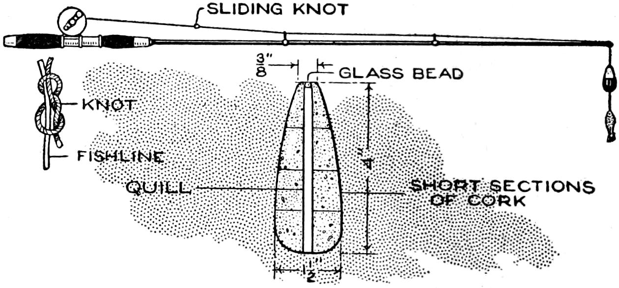
By Setting a Sliding Knot on the Line, as a Stop for the Float, the Depth at Which the Sinker is Desired can be Easily Regulated
Cork is a good material from which to make the float. Cut the cork in sections, as shown, and fit it over a large quill, which provides a smooth-running hole through the float. Fit a small glass bead in the upper end of the float, as a stop for the knot. The knot is of the figure-eight type, and tied as shown in the detail at the left. It slides easily, but grips the line tightly enough to stop the float. An ordinary float can be altered for use as described.—Charles Carroll, Baltimore, Maryland.
[9]
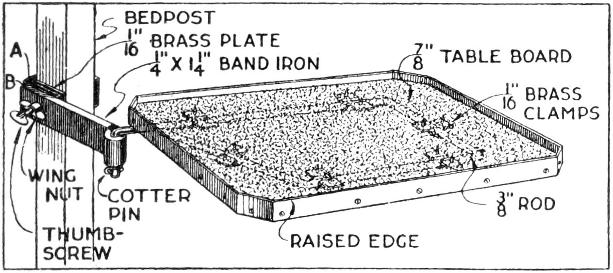
This Handy Table Clamps on the Bedpost and can be Swung Aside Conveniently, or Removed Altogether
A table arrangement which can be clamped handily to the bedpost and swung out of the way or removed altogether when not in use, is a convenience that has a wide use in the home. A device of this kind, which requires no floor support and can be folded compactly for storage, is shown in the illustration. The table proper consists of a ⁷⁄₈-in. board, of suitable size, the edges of which are banded with metal or thin wooden strips. The board is supported on a frame of iron rod, bent to the form indicated in the dotted lines, and clamped with ¹⁄₁₆-in. brass clamps. The end of this frame rod is bent at an angle and pivoted in a metal bracket. A cotter pin guards against accidental loosening of the joint. The clamping device is made of ¹⁄₄ by 1¹⁄₄-in. band iron, and is bent to fit loosely around the bedpost. A brass plate, A, is fitted inside of the main piece B, as shown. A thumbscrew is threaded into the piece B, its point engaging the brass plate, which acts as a guard. In fastening the piece B on the bedpost, the thumbscrew is set, and the wing nut also tightened.—A. Lavery, Garfield, N. J.
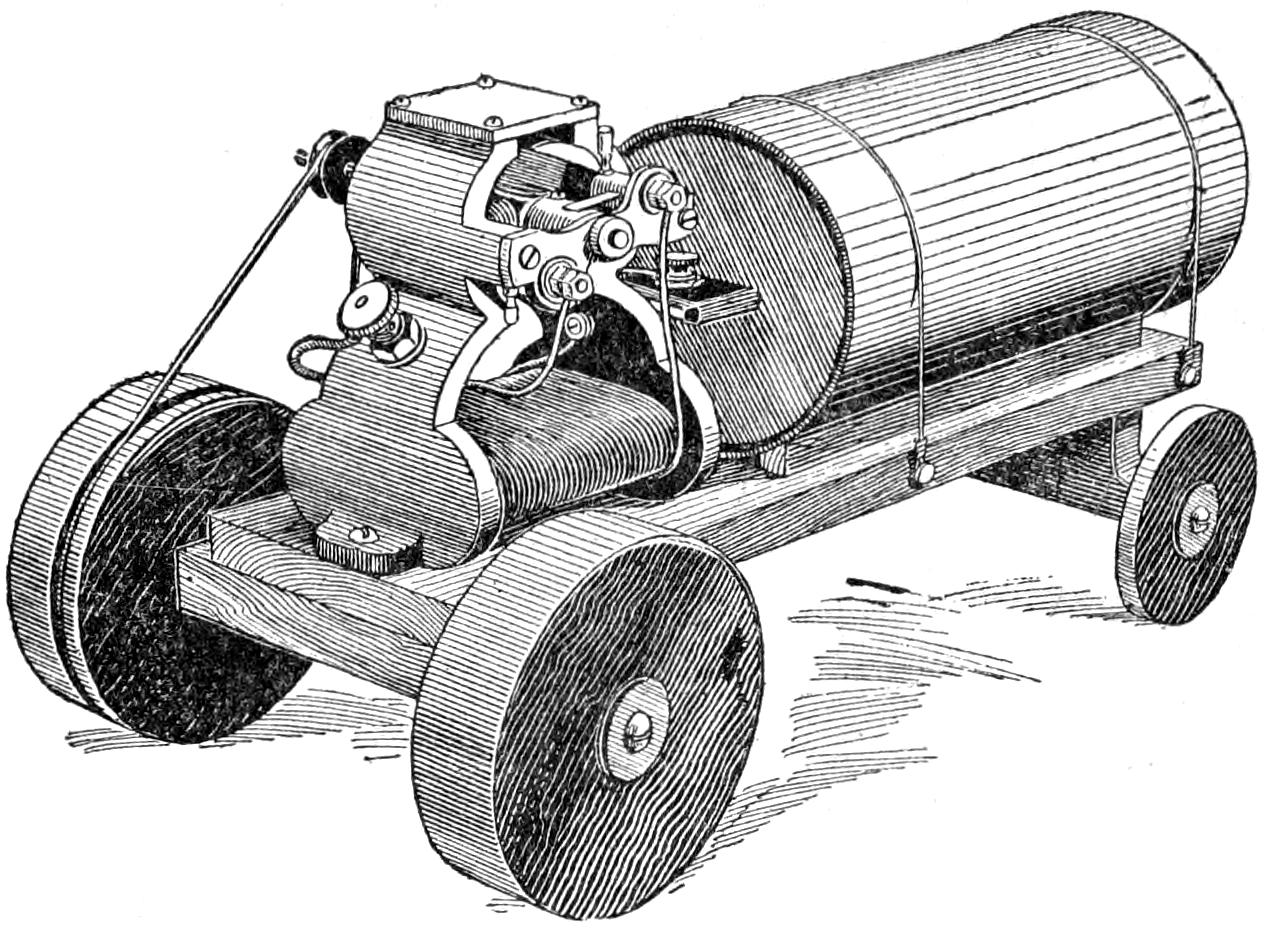
A Boy can Make This Simple Electric Tractor in a Short Time, and will Get Much Fun Out of It
An ordinary two-volt dry cell, a small motor, and the necessary wooden parts, as shown in the illustration, are all that is needed for the making of a toy tractor that will give its builder a great deal of fun. A good feature is that the parts can be taken down quickly and used for other purposes when desired. A base, ¹⁄₂ by 3 by 9 in. long, is made of wood, and two axles of the same thickness are set under it, as shown. The wheels are disks cut from spools, or cut out of thin wood for the rear wheels, and heavier wood for the front ones. They are fastened with screws and washers, or with nails. The dry cell is mounted on small strips and held by wires. The motor is fastened with screws and wired to the dry cell in the usual manner. One of the front wheels serves as the driver, and is grooved to receive the cord belt.—J. E. Dalton, Cleveland, O.
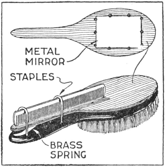
A compact outfit, which the soldier or camper will appreciate, consists of a comb, brush, and mirror, clamped together, as shown in the sketch. Two long staples are set into the back of the brush handle, as indicated. From a board, ¹⁄₄ in. thick, the backing for the metal “trench mirror” is made, with the handle portion small enough to fit into the staples. A small brass strip acts as a spring when placed near the end of the mirror handle, and holds the outfit snugly.
[10]
The common method of preserving leaves by pressing them with an iron rubbed on beeswax may be improved by substituting the following process. Paint the under side of each leaf with linseed oil, ironing it immediately, and then paint and iron the upper side in the same way. This treatment gives the leaves sufficient gloss, while they remain quite pliable. It is not necessary to press and dry the leaves beforehand, but this may be done if desired. The tints may even be well preserved by painting only the upper side of the leaves with the oil and then placing them, without ironing, between newspapers, under weights, to dry.—Caroline Bollerer, New Britain, Conn.
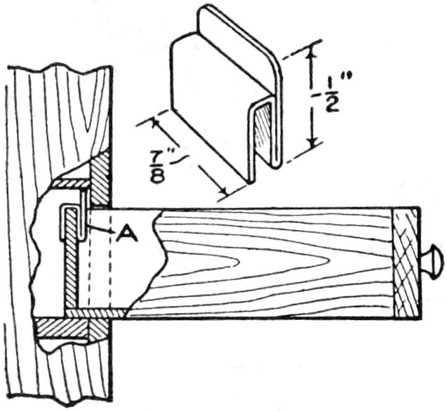
When I least expected it, the small-tool drawers of my tool chest have often dropped out, after I had left them partly open. The result was a waste of time in picking up the tools, not to mention the possible injury to them. I made small clips, like that shown in the sketch, and fitted them to the back of the drawers, as at A. When it is desired to remove the clips, the portion that extends above the drawer may be bent forward. This is necessary only where the space above the drawer is small. The clips may be made large enough to fit drawers of various sizes.—J. Harger, Honolulu, H. I.
A rug may be handled easily for cleaning if the pole on which it is rolled when purchased is used as a support, as shown in the illustration. Two stout wires are fastened into the ends of the pole and hooked over the tightly stretched clothesline. The rug is suspended on the roller and is thus kept straight while it is cleaned, the tendency being, when only a clothesline is used, to crumple at the middle.—John V. Loeffler, Evansville, Ind.
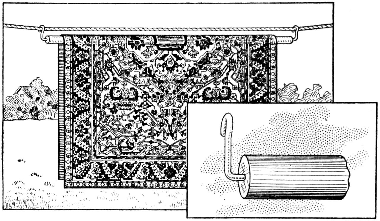
The Roller on Which the Rug is Rolled When Purchased is Used to Advantage as a Support While Cleaning It
A serviceable wheel for banding hand-painted china may be had by adapting a disk talking machine for the purpose. Three old records are placed on the wheel, so as to bring the surface of the upper one slightly higher than the center pin. The piece of china to be banded is set on the exact center of the disk, with the rings on the record as a guide, and the brush may be rested on the arm of the machine. Care must, of course, be taken not to injure the talking machine.—Mrs. W. Read Elmer, Bridgeton, N. J.
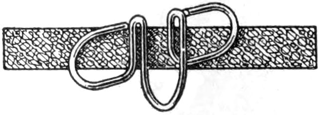
Requiring a collar button, and, as usual, having no extra one on hand, I devised the holder shown in the illustration. It proved to be better than a collar button for use at the back of the neckband. It was bent into shape from a hairpin and has the advantage of keeping the collar fixed with little chance of becoming unfastened.—William S. Thompson, Hopkinsville, Ky.
[11]

Essentials of a good toboggan, whether for coasting or use in transportation, are strength and lightness, and when it is to be made in the home shop, the construction must be simple. That shown in the illustration, and detailed in the working sketches, was designed to meet these requirements. The materials for the toboggan proper and the forms over which it is bent, may be obtained at small expense.
Smoothness of finished surface, freedom from tendency to splinter, and ability to stand up under abuse being requisite qualities in the wood used to make a toboggan, three varieties may be mentioned in their order of merit: hickory, birch, and oak. Birch is softer than hickory and easily splintered, but acquires an excellent polish on the bottom. Oak stands bending well, but does not become as smooth on the running surface as close-grained woods. Do not use quarter-sawed oak because of the cross-grain flakes in its structure.
While the best toboggan is made of a single board, both the securing of material and its construction are rather difficult. Narrow strips are easily bent to shape, but do not make a durable article. A toboggan made of four boards is practical. The mill bill for one 7¹⁄₂ ft. long by 16 in. wide and for the bending frame, is as follows:
| 4 | pieces, | ⁵⁄₁₆ | by | 4 | in. | by | 10 | ft., | hard | wood. | |
| 7 | „ | 1 | by | 1 | in. | by | 16 | in., | „ | „ | |
| 2 | „ | ¹⁄₂ | by | 1 | in. | by | 16 | in., | „ | „ | |
| 2 | „ | 1 | by | 6 | in. | by | 6 | ft., | common boards. | ||
| 6 | „ | 1 | by | 2 | in. | by | 18 | in., | „ | „ | |
| 1 | cylindrical block, 12 in. diameter by 18 in. long. | ||||||||||
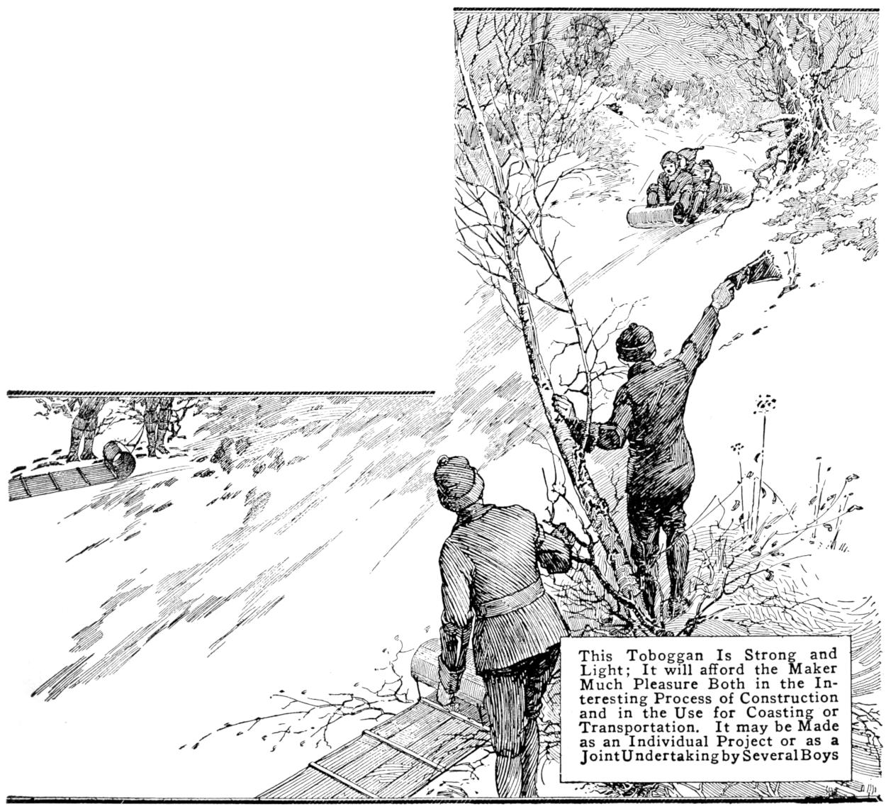
This Toboggan Is Strong and Light; It will afford the Maker Much Pleasure Both in the Interesting Process of Construction and in the Use for Coasting or Transportation. It may be Made as an Individual Project or as a Joint Undertaking by Several Boys
[12]
The form for the bending of the pieces is made of the common boards and the block. A block sawed from the end of a dry log is excellent. Heat it, if convenient, just before bending the strips. The boards for the bottom should be selected for straightness of grain and freedom from knots and burls. Carefully plane the side intended for the wearing surface, and bevel the edges so that, when placed together, they form a wide “V” joint, half the depth of the boards. The 1 by 1-in. pieces are for cross cleats and should be notched on one side, 1 in. from each end, to receive the side ropes. The two ¹⁄₂ by 1-in. pieces are to be placed one at each side of the extreme end of the bent portion, to reinforce it.
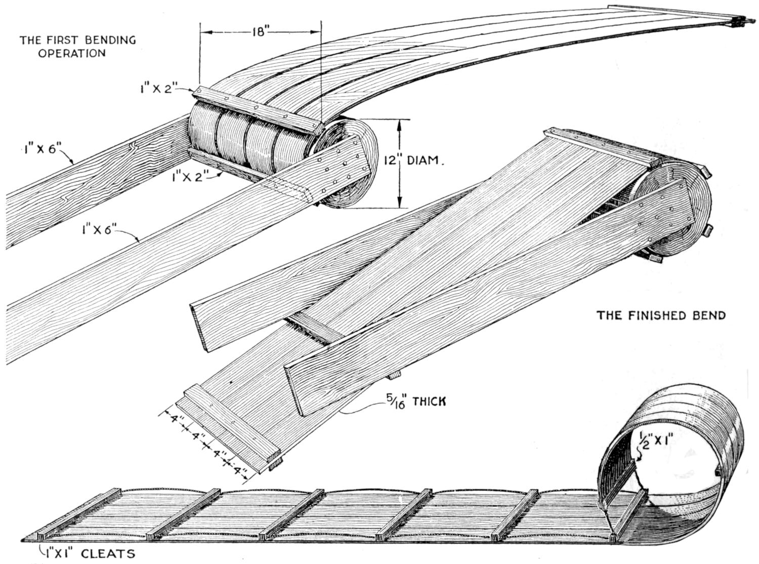
The Boards for the Bottom are Steamed or Boiled at the Bow Ends and Bent over the Form. As the Bending Operation Progresses, the Boards are Nailed to the Form with Cleats, and Permitted to Dry in This Position
Bore a gimlet hole through the centers of the 1 by 2 by 18-in pieces, and 4¹⁄₄ in. each side of this hole, bore two others. Nail the end of one of the 6-ft. boards to each end of the block, so that their extended ends are parallel. With 3-in. nails, fasten one of the bored pieces to the block between the boards, inserting, temporarily, a ¹⁄₂-in. piece to hold it out that distance from the block.
Steam about 3 ft. of the ends of the boards, or boil them in a tank. Clamp, or nail, the boards together, at the dry ends, edge to edge, between two of the 1 by 2-in. pieces, leaving about ¹⁄₄-in. opening between boards. Thrust the steamed ends under the cleat nailed on the block, the nails which hold it slipping up between the boards. Bear down on the toboggan carefully, nailing on another of the bored cleats, when the toboggan boards have been curved around the block as far as the floor will permit. The nails, of course, go between the boards.
Now, turn the construction over and bend up the toboggan, following the boards around the block with more of the nailed cleats, until the clamped end is down between the two 6-ft. boards,[13] where it can be held by a piece nailed across. More of the cleats may be nailed on if desired; in fact, the closer together the cleats are the less danger there is of splintering the boards, and the more perfect the conformity of the boards to the mold.
Allow at least four days for drying before removing the boards from the form. Clamp the ¹⁄₂ by 1-in. pieces one each side of the extreme ends of the bent bows, drill holes through, and rivet them. A 1 by 1-in. crossbar is riveted to the inside of the bow at the extreme front and another directly under the extremity of the curved end. These cleats are wired together to hold the bend of the bow. The tail end crossbar should be placed not nearer than 2¹⁄₂ in. from the end of the boards, while the remainder of the crossbars are evenly spaced between the front and back pieces, taking care that the notched side is always placed down. Trim off uneven ends, scrape and sandpaper the bottom well, and finish the toboggan with oil. Run a ³⁄₈-in. rope through the notches under the ends of the cross pieces, and the toboggan is completed.
Screws are satisfactory substitutes for rivets in fastening together the parts, and wire nails, of a length to allow for about ¹⁄₄-in. clinch, give a fair job. Indians overcome the lack of hardware by the use of rawhide, laced through diagonally staggered holes bored through the crosspieces and bottom boards. Rawhide, which they sometimes stretch over the bow as a protection, affords an opportunity for elaborate ornamentation.
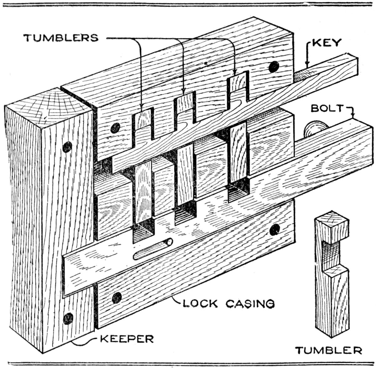
This Lock is Made Entirely of Wood and cannot be Picked Easily
The lock shown in the sketch and detailed drawings is made entirely of wood, and it is nearly impossible to pick or open it without the use of the key. The casing of the lock is 5 by 5 in. and 1 in. thick, of hard wood, oak being suitable for this as well as for the other parts. Three tumblers, a bolt, and a keeper are required. The key is shown inserted, indicating how the tumblers are raised by it. The bolt is slotted and a screw placed through it to prevent it from being moved too far. The lock and keeper are bolted into place on a door with carriage bolts, the heads being placed on the outer side.
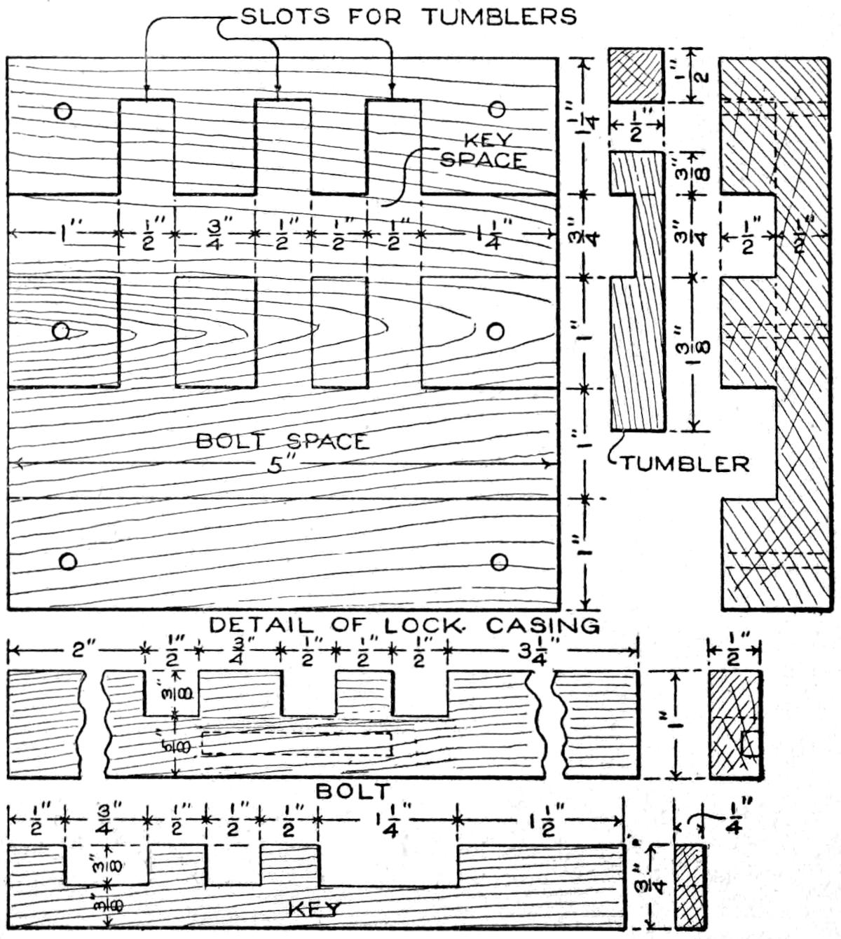
The Details of Construction must be Observed Carefully and the Parts Made Accurately to Insure Satisfactory Operation
The detailed drawing shows the parts, together with the dimensions of each, which must be followed closely.
The lock casing is grooved with two grooves, extending the length of the grain and connected by open mortises,[14] all ¹⁄₂ in. in depth. The spacing of the mortises and the grooves is shown in the views of the casing. Three tumblers, ¹⁄₂ in. square and 2¹⁄₂ in. long, are required. The bolt is ¹⁄₂ by 1 by 8 in., and the key ¹⁄₄ by ³⁄₄ by 5¹⁄₂ in., and notched as shown. All the parts of the lock must be fitted carefully, sandpapered smooth, and oiled to give a finish that will aid in the operation, as well as protect the wood. Aside from its practical use, this lock is interesting as a piece of mechanical construction.—B. Francis Dashiell, Baltimore, Md.
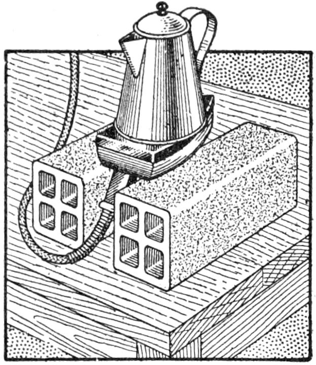
A milliner, in addition to using her electric iron for ordinary purposes of ironing and pressing, inverts it between two hollow tiles and thus makes use of it in steaming velvet trimmmings. The tiles not only hold the iron securely in this position, but also insulate it from overheating or scorching adjoining objects or surfaces. The iron is also used inverted for heating water, cooking coffee, and other liquids, as well as in providing a warm lunch.
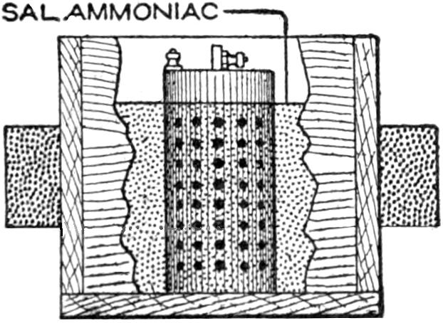
Finding that dry batteries had increased in price, and requiring a number for experimental purposes, I devised the following method by which I was able to use the old batteries for a considerable period: When the dry cells were nearly exhausted, I punched holes through the zinc covering with a nail, as shown in the sketch. The holes were placed about 1¹⁄₂ in. apart, and care was taken not to punch them near the upper edge of the container, or the black insulation might thus be injured. The cells were then placed in a saturated solution of sal ammoniac. The vessel containing the liquid must be filled only to within ¹⁄₂ in. from the top of the cell, otherwise the binding posts will be corroded, and the cell probably short-circuited. The cells were left in the solution six hours, and then became remarkably live. They must not be connected or permitted to come into contact with each other while in the solution.—H. Sterling Parker, Brooklyn, N. Y.
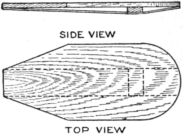
The simple device shown in the sketch can afford youngsters much amusement in coasting down inclines or small hills, either on the snow or on surfaces slightly crusted with ice. The board is intended for individual use only and should be about 10 in. wide and 26 in. long. It is reinforced underneath by a strip of wood, about ¹⁄₄ in. thick and smoothed on its lower side. This piece is fastened in the form of a bow by placing a small cleat between it and the upper piece. The strip should be about 3 in. wide, and aids in keeping the sliding board in its course.—John F. Long, Springfield, Mo.
Converting an ordinary parlor, or mantel, clock into a master clock, from which the striking of the gong is transmitted to various parts of the home, may be accomplished by fitting it with a simple electrical device, as shown in the sketch. The general arrangement of the batteries, single-stroke bells, and[15] the contact device within the clock case is shown in Fig. 1; a detail of the silk cord and other connections of the contact key and the gong hammer, is shown in Fig. 2. This arrangement has been in operation for several years, and has been found practical.
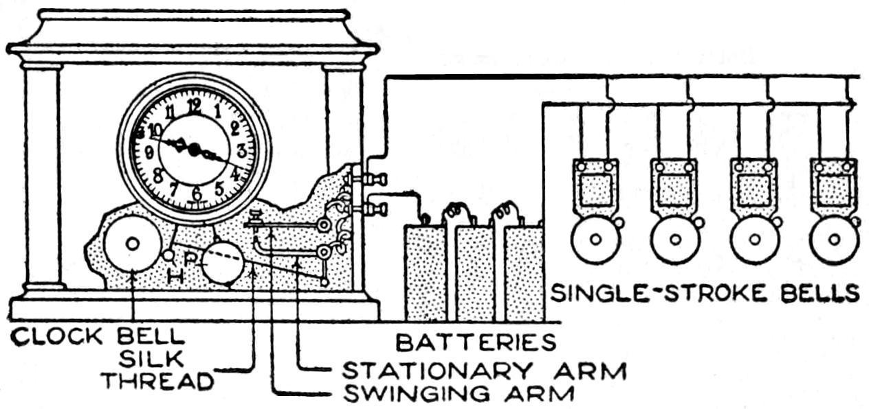
Fig. 1
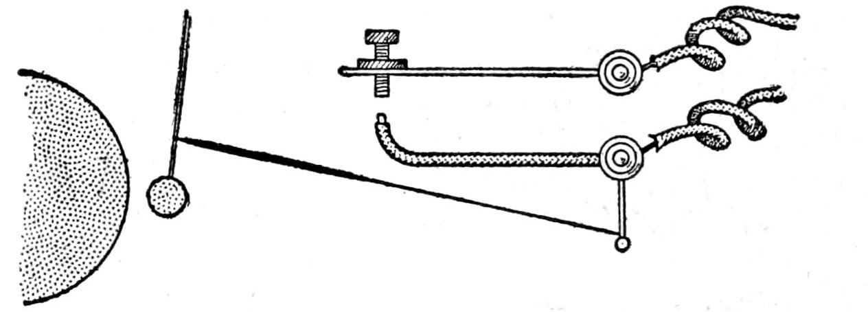
Fig. 2
The General Arrangement of the Apparatus for Transmitting the Striking of a Clock Gong is Shown in Fig. 1, and a Detail of the Contact Device in Fig. 2
The various rooms to which the striking of the gong is to be transmitted are wired with No. 18 annunciator wire, run carefully behind picture moldings and in corners. Where the wires must be carried through a partition, a ¹⁄₄-in. hole is sufficiently large for the purpose. The single-stroke bells are wired up as shown in the sketch. The number of dry batteries necessary varies with the number of bells in the circuit, and also depends on the length of wire through which the current is carried. A trial should be made with several batteries and more added until the bells are rung properly.
The connecting device may be fitted into the clock case without defacing it by boring holes in its side, and the binding posts are fixed into place neatly. The two sections of the contact key, shown in detail in Fig. 2, are fastened to the back of the clock case with bolts. The upper member is fitted with an adjustable thumbscrew and is stationary on the bolt fastening. The lower arm is made of covered wire and is pivoted on the supporting bolt. Attached to its lower edge, at the pivot, is a small lever arm. This is connected to the hammer rod of the gong with a silk cord. The length of the cord must be determined by careful adjustment so that it will not hinder the action of the hammer H, but will bring the swinging arm into proper contact with the thumbscrew. The contact should be made at the instant the hammer strikes the bell. The contact of the platinum point of the thumbscrew and the swinging arm must be close, but not too strong. Metal posts or tubes fitted over the bolts, at the points where the arms are attached to the back of the clock case, may be used to bring the arms the proper distance forward in the case, so that they will be in alinement with the hammer rod. The silk cord must not interfere with the action of the pendulum P. To hold the silk cord in place on the hammer rod, drop a small piece of melted sealing wax or solder on the rod.—W. E. Day, Pittsfield, Mass.
Some old headboards of beds are of such a pattern that they lend themselves readily for use as signboards, with only slight alteration. Such an adaptation is shown in the sketch, and was fitted to a bracket of ornamental iron, the whole producing a striking effect. The sign was made of black walnut and was, by reason of its age, well seasoned. It was treated with several coats of linseed oil to withstand the action of the weather better.

A Signboard Which Attracts Attention was Made of the Headboard of a Walnut Bed
[16]
A baking-powder, or other tinned, can may be used to make the small automobile horn shown in the illustration, for use on a child’s coaster wagon. The device consists of a toothed wheel operating against several metal pawls within the can, and the warning sound is produced by turning a small crank at the end of the can. The can is fixed to the side of the vehicle by means of a wire or strap-iron bracket, as shown in the sketch at E.
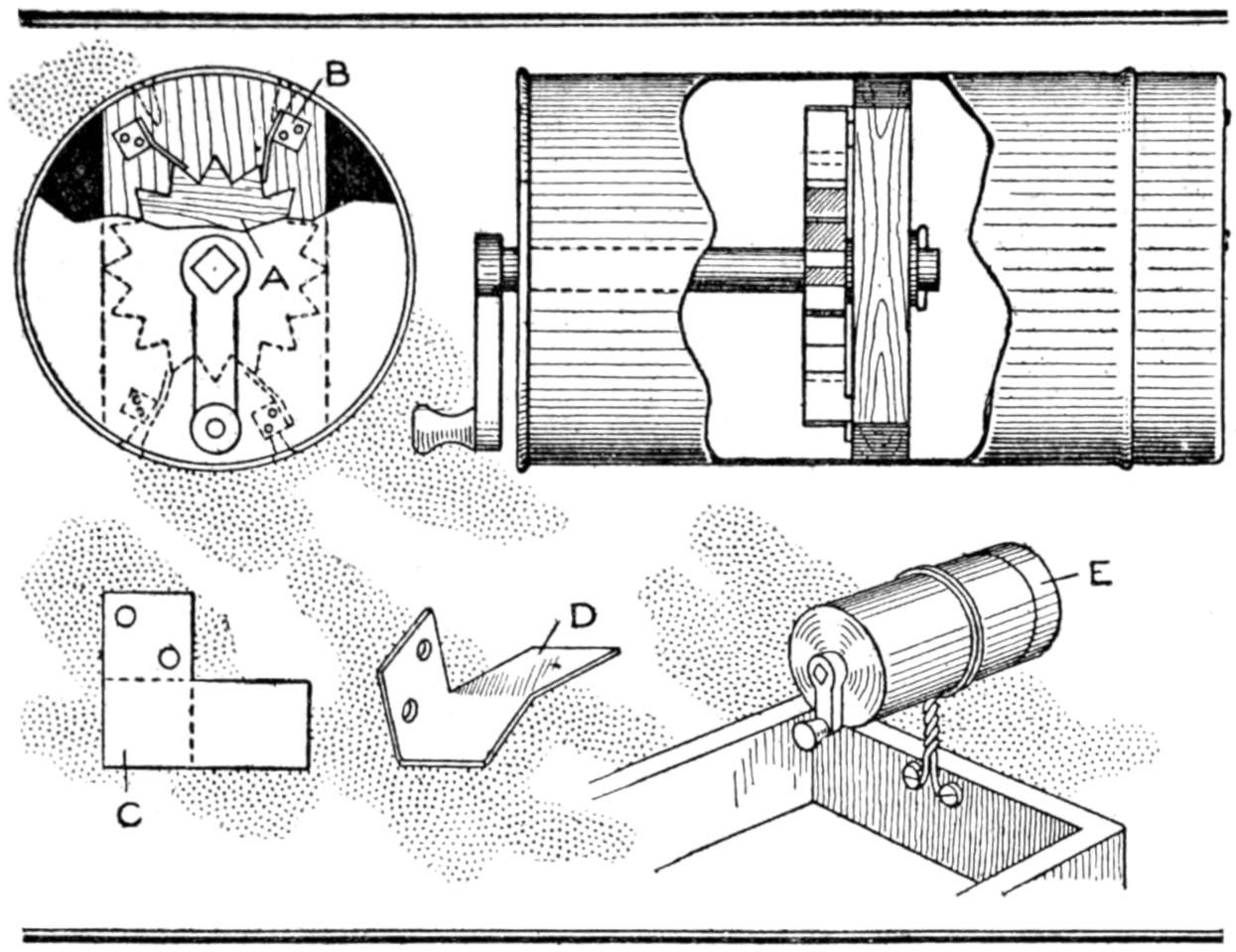
This Small Auto Horn was Made of a Tinned Can Fitted with a Notched Wheel and Pawls
A piece of wood is fitted into the can, to support the ratchet wheel. It is bored to carry a shaft, which bears in the end of the can, and at the exposed end of which is fixed a crank. A disk of wood, about ¹⁄₂ in. thick, is cut to have a notched edge, as shown at A. The notched wheel is placed upon the shaft, and fastened securely to it, so that the ratchet wheel revolves with the shaft when the crank on the latter is turned. Four small pawls of sheet metal, are fixed on the inner support, as shown at B. They are made by cutting pieces of metal to the shape shown at C, and folding them, as shown at D. They are fastened to the support with small screws or nails. The cover is placed on the end of the can when the device is used. The action of the ratchet wheel against the pawls is to produce a loud grating sound, resembling that of a horn of the siren type.—William Freebury, Buffalo, N. Y.
A small paste tube of the collapsible variety is hard to keep at hand on the desk and occasionally, if left uncovered, the contents may be forced out on papers or on the table. A simple container may be made for the tube by cutting the carton in which the tube is packed with a penknife, so as to expose the upper end of the tube. The cover and upper end of the back of the carton is doubled over to provide an extra thickness for a support, by which the contrivance may be suspended on the wall.—T. H. Linthicum, Annapolis, Md.
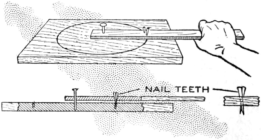
Draw the Strip with Its Saw-Tooth Brads around the Center, Cutting Out the Disk
Instead of cutting thin wooden disks with a coping saw, making it necessary to smooth off the circumference of the disk, more satisfactory results may be had by the following method: Determine the center from which the circumference of the disk is to be struck. Drive a nail through a strip of wood about 1 in. wide and ¹⁄₄ in. thick, and into the center of the proposed disk. At a point on the strip, so as to strike the circumference of the disk, drive two sharp brads, as shown in the sectional view of the sketch, arranging them to act as saw teeth, by driving them at an angle, with a slight space between the points. By grasping the end of the strip and drawing it carefully around the center a number of times, the disk may be cut cleanly. By cutting from one side nearly through the board, and then finishing the cut from the other, an especially good job results.—S. E. Woods, Seattle, Wash.
[17]
A WISHBONE-MAST
ICE YACHT
by John F. Pjerrou
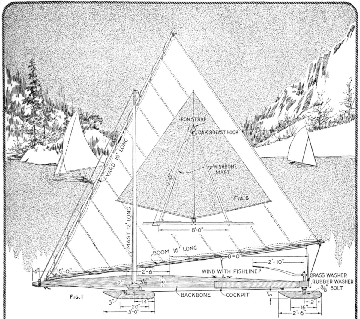
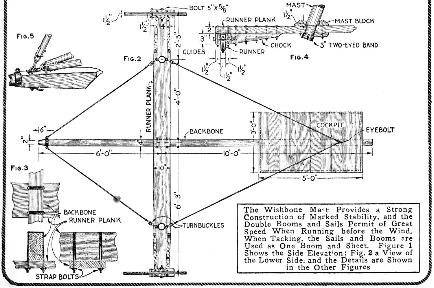
Large spread of canvas and great speed when running with the wind, or “free”; stability under heavy wind, and adaptability to sailing under conditions similar to those of the common, single-boom-and-sheet ice boat, are the features of the ice yacht shown in the illustration. The runner and frame structure is in general typical of ice-boat construction. The double, or wishbone, mast is distinctive, as is the double-boom and sail arrangement, shown in Figs. 1 and 6. The booms are pivoted at the bow of the craft, and controlled at the stern by the usual line and pulley rigging. The booms may be spread so that a V-shaped cavity is afforded for taking the wind when running free, or they may be brought together and both sails manipulated as a single sheet. Reefing and lowering of the sails are accomplished in the usual manner. The framework is very substantial and the proportions are of moderate range, so that the craft may be constructed economically for one or two passengers. The double-boom feature may be omitted if the craft is to be used where little or no opportunity is afforded for running before the wind, by reason of the particular ice areas available. For the experimenter with sailing craft, the wishbone-mast ice yacht affords opportunity for adaptation of the various elements of the craft described, and is a novelty. The dimensions given are for a small yacht, and care must be taken, in adapting the design, to maintain proper proportions for stability and safety. A side view with working dimensions is shown in Fig. 1; inset into it is Fig. 6, showing a front view of the mast and sail arrangement. Figure 2 shows a view of the framework from below. A detail of the fastening of the backbone and runner plank is shown in Fig. 3; a detail of the fastening of the masts and the forward runners into the runner plank, in Fig. 4, and the fixture by which the booms and the yard are attached to the forward end of the backbone, in Fig. 5.
The construction should begin with the making of the lower framework, as shown in Fig. 2 viewed from the lower side. The main frame consists of a backbone, of spruce or white pine, 4 in. thick, 8 in. high at the center, and 16 ft. long, clamped accurately at right angles to a runner plank, of the same material, 2 in. thick, 10 in. wide, and 12 ft. 6 in. long. The backbone is tapered from the middle portion, 5 ft. 6 in. from the forward end, and with a ridge, 8 in. high and 2 ft. 6 in. long, measured from the end of the taper at this end, as shown in Fig. 1. It is tapered to 4 in. at each end, and the bow end is fitted with a three-eye metal ring, as shown in detail in Fig. 5. The runner plank and the backbone are clamped together firmly at their crossing, the backbone being set upon the plank, by means of two strap bolts, with washers and nuts, as shown in detail in Fig. 3. Only the best material should be used in the backbone and runner plank, and the stock should be straight-grained, to give the greatest strength.
The runner plank is tapered down to 8 in. at its ends, to which the guides for the forward runners are fixed. The guides are of straight-grained oak, 1¹⁄₂ by 3 by 14 in., bolted to the runner plank with ⁵⁄₁₆-in. carriage bolts, as[18] shown in the detail sketch, Fig. 4, and in Fig. 2. The guides and the ends of the plank are reinforced with oak chocks, bolted in place at each of the tapered edges of the plank. The forward runners are of oak, 1¹⁄₂ by 5 by 36 in., shaped at their ends as shown, and shod with half-round strap iron. The heads of the screws used for this purpose are countersunk carefully. The runners are pivoted on ⁵⁄₈-in. bolts, the nuts being set to the inner side. Washers and jam nuts should be provided, or the ends of the bolts riveted slightly, to prevent the nuts from becoming loosened.
The stern runner is of oak, 1¹⁄₂ by 5 by 30 in., shod like the forward runners, and is pivoted in a forged wrought-iron hanger. The lower portion of the hanger may be made of a strip of heavy iron, bent into a U-shape, and drilled to receive a ³⁄₈-in. bolt, on which the runner pivots. The U-shaped piece is riveted firmly to a vertical shaft, provided with a heavy rubber washer, protected from wear by a metal one, as indicated at the right in Fig. 1. The upper end of the shaft is threaded to receive a washer and nut. A section of pipe is fitted over the shaft, and the steering handle, fitted to a square section of the shaft, is clamped securely.
The cockpit is fixed to the lower side of the backbone, and is 5 ft. long and 3 ft. wide, with coaming, 4 in. high. It is shown with square corners, since this construction is convenient, though not as good as the type having the ends of the cockpit rounded, and fitted with coaming steamed and bent to the curve. The floor of the cockpit is fastened to the backbone with lag screws, and the coaming is also fastened securely; this construction, if carefully made, will afford ample strength. If desired, especially in larger craft, ribs may be fixed to the backbone, to carry the cockpit.
The runners, the runner plank, and the backbone must be alined carefully, so that they are at right angles, and track properly; otherwise the craft will not keep a true course, and cannot be controlled properly by the rudder runner. The backbone and runner plank are held rigidly by four ¹⁄₄-in. wire-rope stays, shown in Fig. 2. They are fixed to eyes on the bands at the bow, near the ends of the runner plank, and to an eyebolt below the cockpit. The stays are provided with turnbuckles, so that they may be adjusted as required. The bands near the ends of the runner plank are fixed to the lower ends of the masts, as shown in detail in Fig. 4, and are reinforced with oak blocks. The ends of the guy wires are fastened to the eyes by looping them and clamping the resulting eye with steel clamps made for this purpose. Metal thimbles may be fitted into the loop of the rope, to make a better finish; other fastenings may easily be devised by one skilled enough to make such a construction.
The wishbone mast is made of two poles of hickory or ash, 3¹⁄₂ in. thick at the base, and tapered to 2 in. at the top. The poles are joined carefully at the masthead, bolted together, and fitted to an oak breast hook, as shown in Fig. 6. An iron strap reinforces the joint, and an eye, fashioned at its upper end, affords a point of attachment for the forward stay of the mast. The lower ends of the poles forming the mast are fitted into sockets in the runner plank, which is reinforced with mast blocks, as shown in Fig. 4. The ends of the mast, projecting beyond the lower side of the runner plank, are fitted with eye bands, used in guying the runner plank and backbone.
The sails are carried on a yard and two booms, of the same material as the masts, each 16 ft. long, 2³⁄₄ in. at the middle and tapering to 1¹⁄₂ in. at the ends. They are fitted with metal rings at the ends to prevent splitting. The yard and booms are fitted to the backbone at the bow by means of loops bolted to them and engaging an eyebolt and ring on the backbone. The eyebolt is fitted into a slotted plate of ³⁄₁₆-in. sheet iron, and fastened by a lever nut, as shown in Fig. 5. The sheets are fastened to the yard and booms in the usual manner, being fitted with grommets, and tied with line. The yard is suspended from the masthead by means of a line and pulley, the former being cleated to the backbone. The booms are controlled by the operator from the cockpit, by the use of lines and pulleys, similar to the arrangement used on sailboats, except that a duplicate set is required for the additional boom. The lines are cleated on the backbone convenient to the cockpit.
[19]
| Fig. 1 Fig. 6 |
||
| Fig. 5 | Fig. 2 | Fig. 4 |
| Fig. 3 | The Wishbone Mast Provides a Strong Construction of Marked Stability, and the Double Booms and Sails Permit of Great Speed When Running before the Wind. When Tacking, the Sails and Booms are Used as One Boom and Sheet. Figure 1 Shows the Side Elevation; Fig. 2 a View of the Lower Side, and the Details are Shown in the Other Figures | |
[20]
The sails are of the lateen type, and should be made of 8-oz. unbleached cotton duck. The breadths are sewn together by lapping one edge over the other about 1 in., and sewing or stitching along the edge. Yard-wide material is satisfactory, and if narrower laps or bights are desired, simply fold over 1 in. of the goods and double-stitch the seam. The bights should run parallel with the after, or leach, edge of the sail, as shown in Fig. 1. Each corner of the sail should be reinforced with a triangular patch of duck, so that it will stand up under the severe strain of winter usage. The edges of the sail may be bound with ¹⁄₄-in. tarred rope, which is not difficult if a sailor’s palm and a diamond-pointed needle are used. Sail twine, well waxed, should be used for the sewing of the sails.
The edges of the sails adjoining the yard and booms are provided with grommet holes by means of which the sails are attached to their supports. The grommets are made by punching holes in the sails, at the proper points, fitting two ³⁄₄-in. brass grommet rings into the holes, one at each side, and overcasting them with a buttonhole stitch. The sail needle and waxed sail twine are used. The reef points are of the usual type, and are made of ¹⁄₈-in. cotton rope, whipped at the ends to prevent raveling, and sewed to the sails at intervals.
The craft is designed to be taken down when not in use, particularly between seasons, and can be stored in comparatively small space, in the knockdown form. The method of setting up the ice yacht will serve to illustrate, also, the method of taking it down, in that the process is practically reversed. First, the backbone is fitted with the forward ring and the strap bolts are fastened at the crossing of the backbone and runner plank. The runners are fitted into place, and the steering rigging is adjusted. The wishbone mast is set into its steps, clamped at its masthead, and the bands fitted to the lower ends. The guy wires at the bottom and that at the masthead are then set, by means of the turnbuckles. The sails are attached to the yard and booms, and the forward end of the latter supports are fixed into place. The pulley at the masthead is fitted with ³⁄₈-in. rope which is fastened to the yard, at the proper point, as indicated in Fig. 1. The rigging by which the booms are controlled is threaded through the pulleys at the stern and the ends fixed on the cleats. The yard may now be hauled up and the craft trimmed so that the sails “set” properly. The halyard is fixed to the yard, as shown, and run through a pulley at the masthead, then down through a second pulley fixed to the runner plank, from which it is conducted to cleats convenient to the operator in the cockpit.
The main sheets are rigged as shown in Fig. 1. The ends of the lines are lashed to the ends of the booms, passed through pulleys, at the stern of the backbone, on the booms, about 1 ft. from the ends, and 5 ft. from the ends, respectively, then down to the cleats at the cockpit. This rigging gives good purchase on the lines and makes it convenient for the operator to attend to the helm and the lines at the same time. The fittings are, as nearly as possible, designed to be standard and may be purchased from ship chandlers, or dealers in marine hardware and fittings. The special metal parts may be made by one of fair mechanical skill, or may be made by local blacksmiths. The woodwork is all comparatively simple. The masts, yard, and booms should be smoothed carefully, sandpapered lightly, and finished with several coats of spar varnish. The other woodwork may be painted suitably, and the metal fittings should be finished with two coats of red lead, or other good paint for use on metals exposed to the weather.
[21]
The manipulation of this craft is in general similar to that of the common lateen-rig, or other sail and ice, boats. When running before the wind—free—the booms are separated and the wind acts against the sails in the pocket between them. When tacking, the booms are brought together, and the sails act as one sheet, on a craft of the ordinary type.
Draftsmen, whose work demands the use of drawing paper of uniform size, sometimes experience difficulty in fixing thumb tacks solidly in the board. This is caused by the continual placing of tacks in the same spot and may be overcome by the use of cork plugs which can be removed when worn. At the four points where the tacks are generally placed, bore 1-in. holes nearly through the board. Insert corks large enough to be forced into the holes and trim them off flush with the surface. Tacks will hold firmly in them and new corks may be inserted as needed. —G. F. Thompson, Pittsburgh, Pa.
A test-tube vase, containing a single blossom, adds color and a certain individual touch to the business man’s desk, or it may be used with effectiveness in the home. A simple wooden stand, finished to harmonize with the surroundings, may be made easily, and affords a support and protection for the test tube. The sketch shows a small stand of this type, made of oak, in the straight-line mission style. It may be adapted to other woods and to various designs in straight or curved lines.
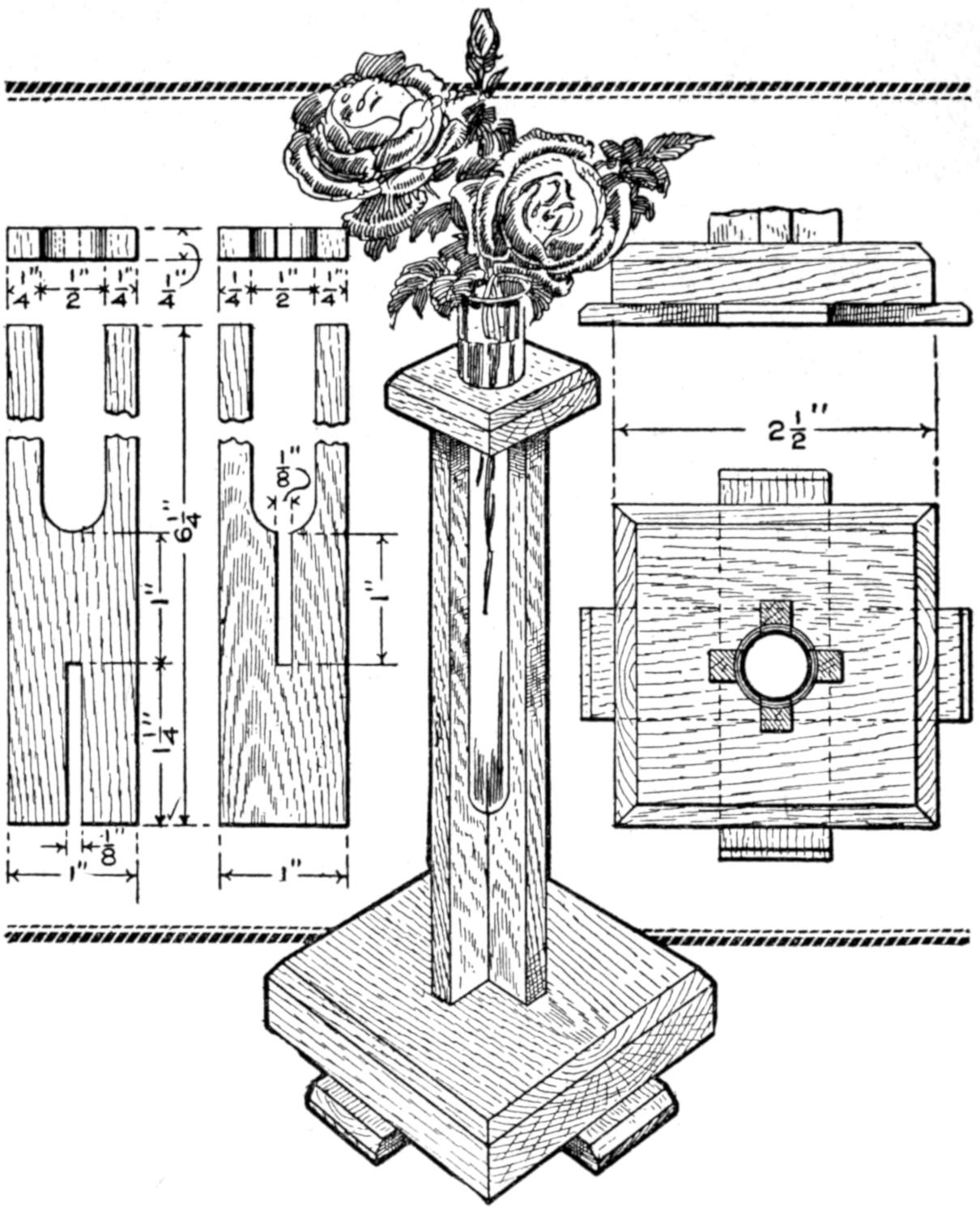
The Stand Provides a Support and Protection for the Test-Tube Vase on the Office Desk or in the Home
The base is 2¹⁄₂ in. square, and rests on two cross strips, 1 in. wide. All the material may be about ¹⁄₄ in. thick, but it is desirable to have the base and cap pieces of thicker stuff. The uprights may be of ¹⁄₈ to ¹⁄₄-in. stuff, and are notched together as shown. They are 1 in. wide and 6¹⁄₄ in. long, a portion being cut out to receive the test tube. The cap is 1¹⁄₂ in. square, and its edges are chamfered slightly, as are those on the upper edge of the base. The pieces are fitted together with small brads, used as hidden dowels, and the joints are glued. Brads may be used to nail the pieces together, and they should be sunk into the wood, and the resulting holes filled carefully. The stand should be stained a dark color, or left natural, and given a coat of shellac or varnish.
In pouring a liquid from a jug or bottle, the vessel should be held with the opening downward, rather than horizontally, if convenient, and swung quickly with a circular motion. The liquid will rotate and in leaving the opening will permit air to enter continuously, causing the liquid to run out rapidly and without intermittent gurgling sounds. If the opening of the container is at one side it is best to hold the container so that the opening is at the highest point of the end rather than at the bottom. The air may thus enter and permit a continuous flow until the container is empty.—E. F. Koke, Colorado Springs, Colo.
[22]
The knife sharpener shown can be easily made of two pieces of thin wood, such as cigar-box covers, about 2 in. wide and 2¹⁄₂ in. long, and two discarded safety-razor blades of the heavier type. Lay the wood pieces together and saw a slot down the center for about 1³⁄₄ in. Lay the two razor blades at an angle of about 2° on each side of the slot, as shown, fasten them to one of the boards, and securely attach the other board over them.
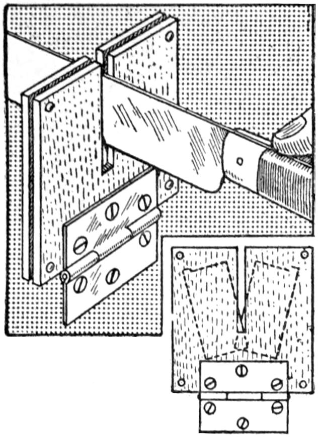
To sharpen a knife, run it through the slot two or three times. The sharpener can be fastened with a hinge so that it will swing inside of the drawer, or box, that the knives are kept in, and it will always be ready for use.—Contributed by Henry J. Marion, Pontiac, Mich.
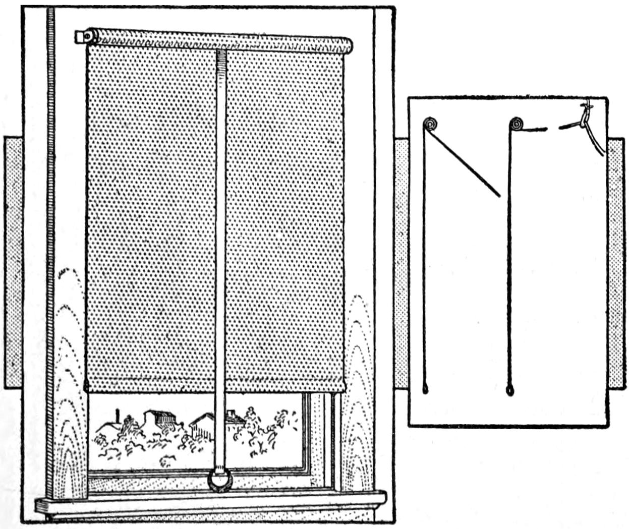
A Ribbon or Tape Attached to a Curtain Roller to Operate It at a Distance
To enable an invalid, or any other person, to easily raise and lower a curtain from a position at a distance from the window, a ribbon can be attached to the roller, at the center and on the inner side of the curtain. The ribbon may extend across the room in line with the window, and still operate the curtain as well as with the regular cord attached to the bottom. If desirable to operate the curtain by a vertical pull, a flat pulley may be conveniently fastened to the ceiling or wall, and the ribbon passed over it, or through a ring, as shown. This plan is especially adapted for show windows where the curtain string would otherwise mar the appearance and be hard to get at.—Contributed by L. E. Turner, New York, N. Y.
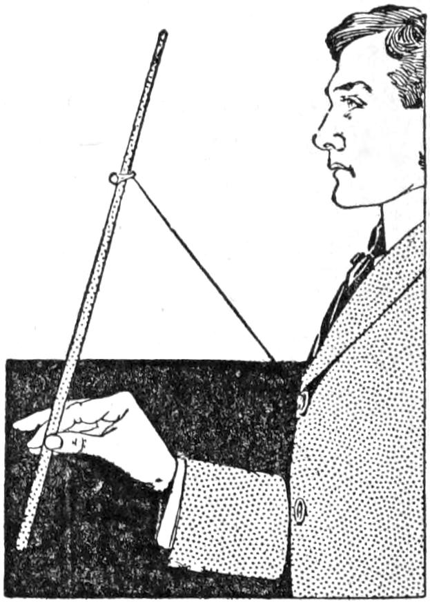
The performer hands out a wand for examination and borrows a finger ring. He holds the wand in his hand, point upward, and drops the ring on it, then makes mesmeric passes over the wand with the other, and causes the ring to climb toward the top, stop at any place desired, pass backward, and at last fall from the wand. The wand and ring are examined again by the audience.
To produce this little trick, the performer must first provide himself with a round, black stick, about 14 in. long, a piece of No. 60 black cotton thread about 18 in. long, and a small bit of beeswax. Tie one end of the thread to the top button on the coat and to the free end stick the beeswax, which is stuck to the lower button until ready for the trick.
After the wand is returned, secretly stick the waxed end to the top of the wand, then drop the ring on it. Moving the wand slightly from oneself will cause the ring to move upward, and relaxing it causes the ring to fall. In the final stage remove the thread and hand out the wand for examination.
[23]

Skis and Ski Running
By Stillman Taylor.
PART I—Prominent Types of
Modern Skis
The requirements of the modern ski call for a hard, flexible, and tough material, and while hickory, white ash, white maple, birch, yellow pine, white pine, and spruce are all used, the experienced ski runner considers hickory and ash to combine in the fullest measure the qualities most desired. Of course, every wood has its limitations as well as merits. Hickory is elastic and fairly tough, but heavy. Ash resembles hickory so far as elasticity is concerned, and its weight is about the same, but the wood contains soft layers. Birch possesses the requisite lightness, but is far too brittle to prove serviceable, and pine is open to the same objection. Maple makes an excellent ski, which can be finished very smooth so as to slide more easily than the other woods, but it is much less flexible than either hickory or ash.
This form of ski, so called from the Telemarken province of Norway, where the art of ski running has reached a high order of skill, is probably the choice of the sportsmen wherever the exhilarating sport of ski running is practiced, and the larger portion of the members of the numerous skiing clubs use the Telemark-model ski. This type is practically identical with the most popular model so long used in Telemarken, and the rule for its selection is to choose a pair whose length reaches the middle joint of the fingers when the arm is stretched above the head. There are various makers of this type of ski, and while the modeling will be found to differ but little, there are numerous brands sold which are fashioned of cheap and flimsy material, and consequently unsatisfactory in every respect.
The Telemark model is shown in Fig. 1, and from this sketch it will be seen that the wood has two curves or bends, one running its entire length to form a graceful arch, and the second, at the toe. The first one is technically known as the “arch,” and the other curve the “bend,” while the front or toe end of the ski is called the “point,” and the rear end the “heel.” In almost all skis the under, or running, surface is provided with a hollow, known as the “groove,” which runs from the heel to the bend. It will be noticed in the drawing that the sides also are gently curved, thus making the ski a trifle broader at the ends than in the center. This curve affords a somewhat greater bend at the heel, and while some experts approve, others disapprove of it, but most ski runners agree that the curve should not be pronounced, or it will prove a handicap and make it difficult for the runner to secure a firm grip at the edge when ascending steep slopes covered with hard snow.
The “arch” of the ski is necessary to avoid bending when the weight of the body is on the runner, and the total height of this important curve should not exceed ³⁄₄ in., for a too exaggerated arch will practically form a concave running surface and retard the speed,[24] since it will run on two edges, or points, instead of on the entire running surface. A slight arch may be reckoned necessary to offset the weight of the body, but the utility of the ski, in nearly every instance, will be less affected by too little arch than by too great a curve at this point.
A good ski is told at a glance by its bend, which must never be abruptly formed, nor carried too high. A maximum curve of 6 in. is all that is ever required, and to prevent breaking at this, the weakest, part of the ski, the bend must be gradual like the curve of a good bow, thus making it more flexible and elastic at this point. As a rule, the ski should be fashioned a trifle broader at the bend than at any other point, and the wood should be pared moderately thin, which will make it strong and resilient with plenty of spring, or “backbone.”
The groove in the running surface is so formed as to make the ski steady and prevent “side slip” when running straightaway. In fact this groove may be compared to the keel of a boat, and as the latter may be made too deep, making it difficult to steer the craft and interfering with the turning, so will the badly formed groove interfere with the control of the ski. The Telemark round-faced groove is by far the best form, and for all-around use is commonly made ¹⁄₁₂ or ¹⁄₈ in. deep. Not all Telemark skis are thus fashioned, however, some being made without the groove, while others are provided with two, and I have seen one marked with three parallel hollows. The shallow groove is the most satisfactory for general use, and while a groove, ³⁄₈ or ¹⁄₂ in. deep, is good enough for straightaway running, it makes turning more difficult.
To attach the ski binding, which secures the shoe to the runner, a hole in the form of a narrow slit is made just back of the center. This is the usual manner of attaching the foot binding, and while it cannot but weaken the ski to a certain extent, it is the best method for making a secure foot fastening, and weakens the wood to a much less extent than the use of bolts, or other metal fastening.
So far as finish is concerned, most Norwegian makers finish their skis with a coat of black paint, while other makers stain the wood, and some finish the wood in the natural color by varnishing. This applies to the upper surface only, the running surface being rubbed down with linseed oil and made smooth with wax.
This type of ski is made quite long and comparatively narrow, with a deep groove, and is well adapted for running on the level or for gliding down slight slopes. This type of ski is commonly used in Lapland and to a less extent in the northern parts of Norway, but the great length and quick, short bend make this model less adapted for ordinary use, since the deep, rectangular groove slows down the speed, and the great length makes turning doubly difficult. For special conditions this type is probably useful, but it can scarcely be considered suited to the average use.
This type of ski is favored by but comparatively few ski runners, and the modeling is inferior to the Telemark ski. The arch is excessive in height, the bend is abrupt and stiff, while the round point, fashioned to prevent sticking in loose brush, has apparently little value in actual use. The Lilienfeld ski is made without a groove, and since the whole model is shorter and broader than the usual type of ski, turning is more easily accomplished, but side slipping is, of course, considerably increased. Ease in turning is a desirable quality, to be sure, but steadiness and immunity from side slipping are far more valuable qualities in a ski designed for all-around use. In short, the Lilienfeld model possesses no decided advantages over the Telemark type, but has many points of inferiority. To one who has used both models there can be no question but that the Telemark model is preferable.
When purchasing skis the sportsman[25] will make no mistake in selecting the Telemark model, and for an active person the skis should be long enough to reach to the middle joint of the fingers, when the arms are stretched above the head, and the ski is stood upright on its heel. The length of a pair so selected will be from 7¹⁄₂ to 8 ft. For elderly and less active persons, for individuals of short stature, and for ladies, skis reaching to the wrist joint will be about right; the length ranging from 6¹⁄₂ to 7 ft. For youths and children shorter skis, from 5 to 6 ft. in length, according to the size and strength of the person, are of course required.
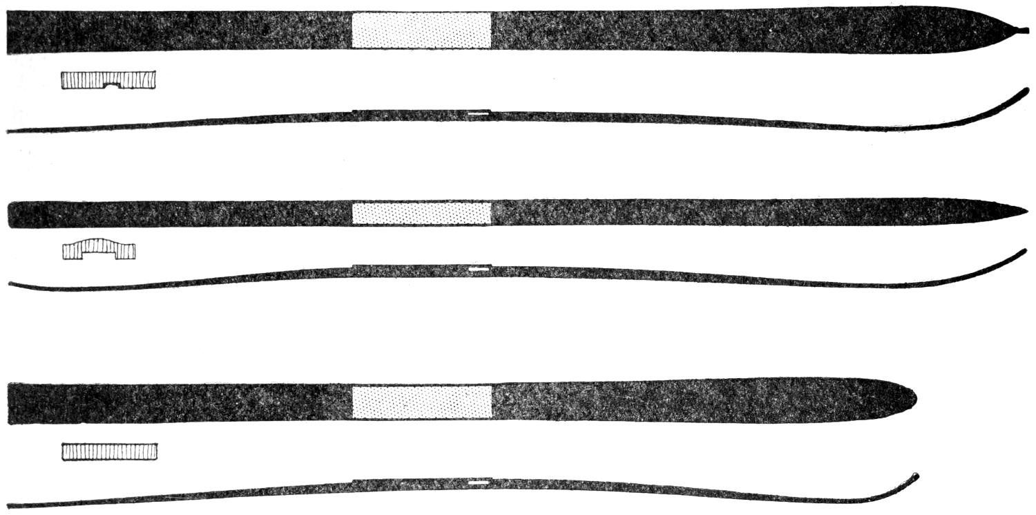
Fig. 1
The Telemark, Swedish and Lilienfeld Models with Grooves and Grooveless Bottoms, the Telemark Being
the Standard and Best All-Around Ski; the Swedish is Long and Narrow with Upturned Heel, and
the Lilienfeld Is Short with a Round Point, More Abrupt Bend, and without a Groove
For all-around use where a large amount of straight running is done, the running surface should be provided with a groove, but if there is not much straight work to be done, and ease in turning is regarded as an important factor, the running surface should be made smooth. This necessitates making the skis to order, for practically all ready-made skis of the Telemark model are fashioned with a shallow groove. However, a groove may be easily cut in at any time if wanted later on. While other types are at times preferred for special use in certain localities, the Telemark-model ski is the standard, being equally good for all kinds of work, straight running, uphill skiing, and for jumping.
The best materials are hickory, or white ash, with a straight, even grain running from end to end. Ash is well liked by many experts, but it would indeed be difficult to find a more satisfactory wood than our American hickory. In fact, many of the most prominent makers in Europe are now fashioning their skis from American timber. As a rule, the best well-seasoned ash, or hickory, is heavier in weight than an inferior grade, and this is why the expert skier considers weight as one of the reliable “earmarks” of first-class material. A good hickory, or ash, ski made by any reputable maker will give the fullest measure of satisfaction.
The finish of skis is purely a matter of personal taste, but practically all Norwegian skis are painted black on the upper side, while a few of the cheaper maple and pine implements are stained. The plain varnished finish protects the wood as well as paint, but allows the grain to show through, and is generally preferred by experts. The running surface must be as smooth as possible to obtain the best speed, and it must not be varnished, the wood being filled with several coats of linseed oil to which a little wax has been added.[26] Tar is used to some extent, but this preparation is mostly employed by Swedish makers.
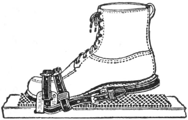
Fig. 2
The manner in which the foot is secured to the ski is highly important, and while various kinds of “bindings” are in use, from the simple cane binding, which marked the first substantial improvement over the twisted birch withes originally used by the peasantry of Telemarken, the Huitfeldt bindings are for many reasons considered the best by experts. The ski runner must have a foot binding that is well secured under all ordinary conditions met with in ski running, and it must be quite rigid and without lateral play. It is desirable also that the foot be freed whenever a fall occurs, thus preventing possible sprains at the ankle and knee, as well as avoiding breakage of the straps. Again the heel of the skier should be free to move up and down for at least 3 in., but the binding should check the vertical movement at this height, thus easing the foot of undue strain when the ski is slid forward, in climbing or working on the level. These essential specifications are so well incorporated in the Huitfeldt model that the description and illustrations of this admirable attachment will suffice. As shown in Fig. 2, the boot is wedged into a firm position between the metal toe piece at the sides. To secure a rigid support, these toe pieces must be firmly wedged in position on the ski, and the skiing shoe should fit between them snugly and well. For this type of binding, a shoe having a stout sole is desirable so that it may keep rigid under the pressure of the body at various angles, and be heavy enough to stand the more or less constant chafing of the metal toe plates. One excellent feature of this binding is the arrangement of the toe and heel straps, which allow all necessary vertical movement of the foot, yet at the same time provide a fairly rigid strong, and reasonably light foot attachment. When fitted with the Ellefsen tightening clamp, and it is a good plan to order the Huitfeldt model so equipped, the skis are easily put on and taken off. A large number of experts prefer this binding above all others, but the Huitfeldt type of binding may be made by the skier if desired. Any metalworker or blacksmith can supply the metal toe pieces, and the binding may be completed by adding suitable straps, or the foot may be secured at the heel by leather thongs.
While there are occasions when the proficient ski runner can dispense with the stick, as in jumping and practicing many fancy turns and swings, a good stick must be reckoned a valuable implement for climbing and downhill running, and often a help on a level. The beginner should not depend too much upon the stick, however, but should acquire the knack of handling the skis without this aid early in his practice. In short, the novice should practice both with and without the stick, that he may learn all the little points of balancing the body unaided, but every skier ought to know how to use the stick, that he may rely upon its assistance whenever necessary.
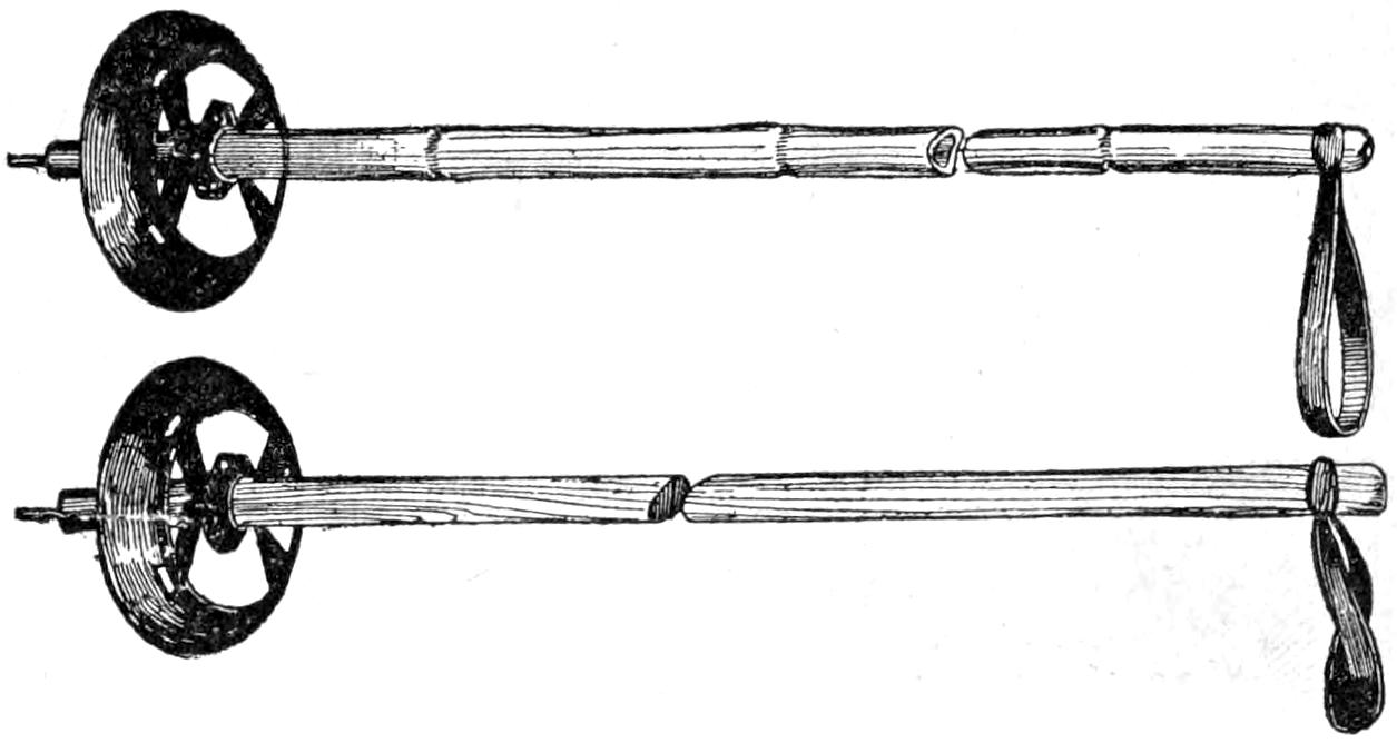
Fig. 3
Skiing Sticks with Staff of Bamboo or Hard Wood
Having an Easily Removable Aluminum Washer
The use of two sticks may be of help for mountain climbing, but the majority of ski runners consider one stout stick to be of more real service. For downhill running, the extra stick is of no value whatever, but rather a hindrance, the one stick being all that is required for braking. In choosing a stick, its height may be such that it will reach to the shoulders of the skier, although many prefer a shorter one. On the average, a stick 5 ft. long will be found about right for most persons, while a proportionately shorter stick will be required for boys and girls. Bamboo of good quality is generally preferred, since it is light, elastic, and very stiff and strong. Hardwood sticks are a trifle heavier, but if fashioned from straight-grain hickory, or ash, are as[27] satisfactory as the bamboo. In any case, the end of the stick should be provided with a metal ice peg, and a ferrule to strengthen the wood at this point. A few inches above the peg a ring, or disk, is fastened, and this “snow washer” serves to keep the stick from sinking too deeply into the snow. Wicker rings, secured with thongs or straps, are much used, as are also disks of metal and hard rubber. A decided improvement over these materials has been brought out in a cup-shaped snow washer made of aluminum, which is flexible and fastened to the stick with clamps so that it can be easily shifted or removed at will. This feature is a good one, since the washer is often useful for assisting braking in soft snow, but is likely to catch and throw the runner if used upon crusted snow, hence the detachable arrangement is of value in that it supplies an easy way to take off the washer whenever desired. The sticks are shown in Fig. 3.
For skiing an ordinary pair of heavy-soled lace shoes that fit well are suitable, but to keep the heel strap of a binding from slipping, the shoes should have broad, concave heels, or a small strap and buckle, firmly sewed in place at the extreme end of the heel, should be fitted to them. Personally, I prefer the heel strap to the special heel, but any cobbler can fit the shoes with either one. Specially designed skiing shoes, or boots, as shown in Fig. 4, are to be had at the sporting-goods dealers’, and while good, are somewhat expensive, because most of them are imported. Of course, shoes for skiing must be amply large so that one or two pairs of woolen socks may be worn; two pairs of thin, woolen stockings being less bulky and very much warmer than one extremely heavy pair.
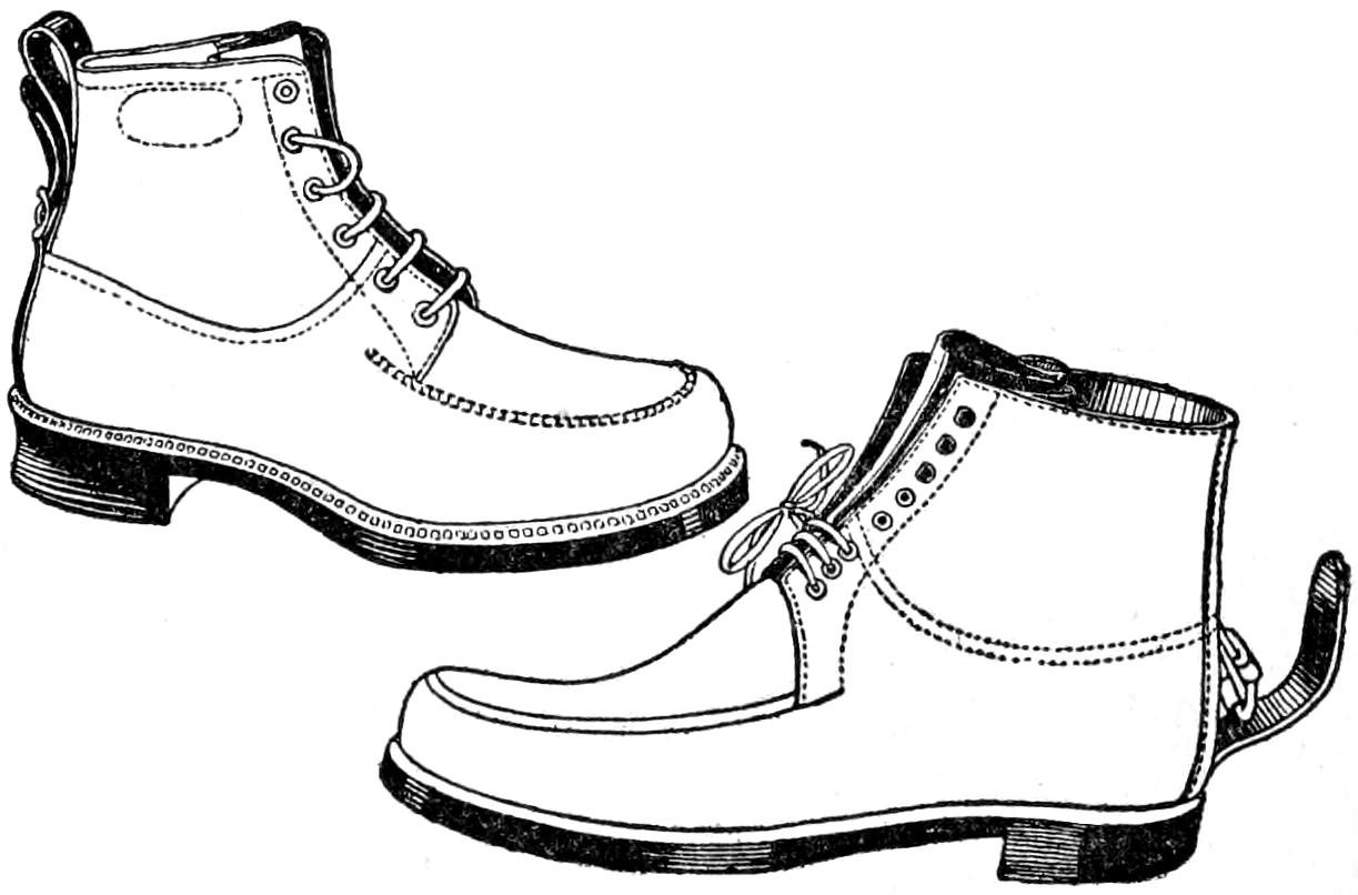
Fig. 4
Specially Designed Skiing
Boots, Handmade for the
Sport, with and without
Heel Buckles
For clothing, the soft, smooth finish of the regulation mackinaw garments cannot be improved upon for outdoor winter wear, although any suitable material will serve as well. Smooth-finish material is the best in all cases, because cloth of rough texture will cause the snow to stick and make it uncomfortable. Regulation mackinaw trousers, split at the bottom and fastened with tapes to tie close to the ankle, are as good as any, over which cloth puttees, or leggings, may be worn to keep out the snow. For the coat, a mackinaw, made Norfolk-style, with belt and flap pockets secured with a button, has given me the most satisfaction. For ladies, close-fitting knickerbockers and leggings are generally preferred when a short skirt is worn.
To anyone who can use a saw and plane, the making of a pair of nicely balanced and durable skis is a very easy job. Ski making is far easier than snowshoe construction, since each runner is made from a single piece of plank, and no intricate filling is required. In choosing the wood, either hickory or ash will give satisfaction, because both are heavy woods, as well as strong and flexible, and may be worked down much thinner than birch, fir, or other materials. If it is desired to fashion the skis from the rough material, procure two ash, or hickory, planks, about 9 ft. long and 2 in. thick. Should the maker wish[28] to hew his own material, select a sound and straight tree, about 10 in. in diameter, free from knots for at least 10 ft., and fell it during the winter. Place the log in the crotch of a stump and cut a groove along its length with the ax, taking pains that the groove is straight and about 1 in. in depth. Turn the log over and make a like groove in the opposite side. Rap the bottom of the grooves lightly with the ax, to start the split, and drive in small wood wedges, gradually working them along as the wood splits. At some points the wood will very likely split away from the groove, but by cutting these fibers, the split may be kept along the grooves. As the strongest and best grain of the wood will lie closest to the bark, only enough of the outside should be hewn away to make a flat surface, for this is to be the running surface of the ski. Skis may be made in any length and width, but for a man of good height, 7 to 8 ft. is the correct length. In Fig. 5 is given a complete layout pattern for an 8-ft. ski, and from the dimensions it is an easy matter to fashion skis longer or shorter by making use of these well-balanced proportions. While the plan of the ski may be drawn directly on the plank, it is an excellent idea to make a paper pattern, and laying this down on the board, trace around it to get the correct outline.

Fig. 5
A Complete Layout Pattern for an Eight-Foot Ski: From These Dimensions It Is an Easy Matter
to Fashion Skis Longer or Shorter by Making Use of These Well-Balanced Proportions
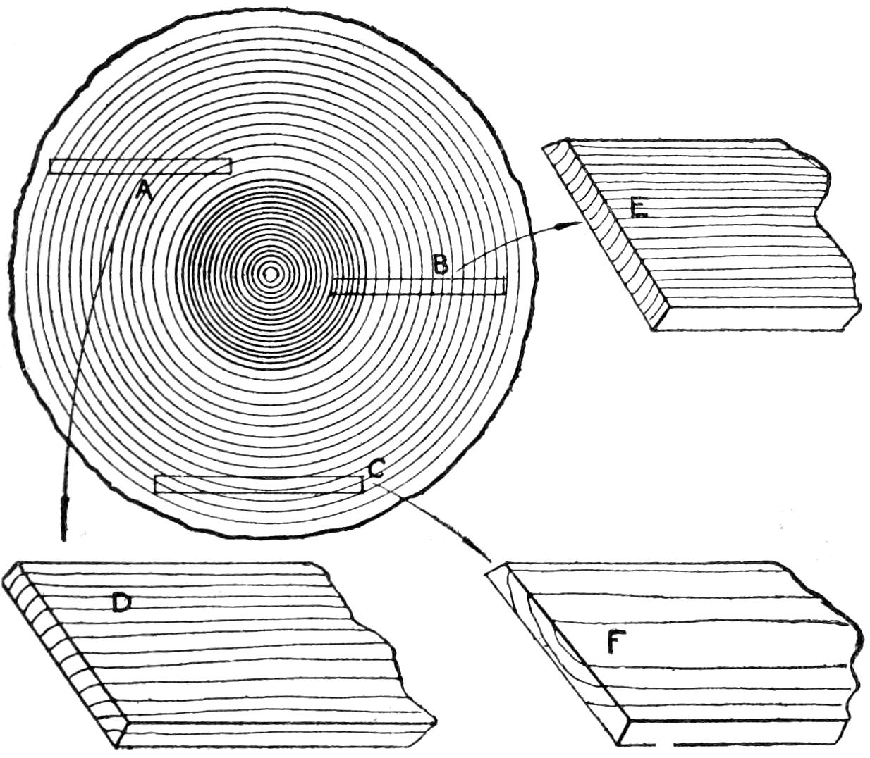
Fig. 6
The Wood is Selected by the Way in Which the
Growth of the Grain Runs
When purchasing the sawed material, the buyer should endeavor to obtain a plank which has been sawed out from the lower portion of the trunk of the tree, from the outside. The dealer will not be able to assist in choosing lumber for this particular purpose, hence the buyer should know something about the growth of good wood in the tree, and how to pick out this desirable material by noting the run of the grain. This is very well shown in Fig. 6. The letters A, B, and C show the run of the grain produced by the ring growth of the tree, and D, E, and F indicate the appearance of rings, in the run of the grain seen in the sawed plank. The best possible choice for wood is represented by A and D, because the layers of good and elastic wood run deep, and there is practically no soft layers of punky wood. That represented by B and E, and that of C and F, contain a larger percentage of soft layers, and while skis can be, and often are, fashioned from this kind of material, the wood is less strong and flexible than that of wood showing the grain as A and D, hence the latter should be chosen whenever it is possible to do so. While wood of fairly close grain does not necessarily indicate inferiority, if the material is hickory, yet if ash is selected, the purchaser should select an open, or widely spaced, grain in preference to a close and even-grained plank. And this is so because in all trees the grain represents the more quickly grown soft wood—formed in the period of greatest growth, which is in the spring and summer months—hence the more grain present in the plank and the closer it runs, the more soft and punky wood is present, and the less durable the material will be for the purpose.
When drawing the dimensions on green, or partly seasoned, timber, a certain amount of shrinkage will occur, hence be sure to allow for this and make the width about ¹⁄₄ in. greater. When working seasoned lumber, this need not be taken into consideration.
[29]
After the outline of the ski has been sawed out, the bottom, or running surface, should be planed perfectly smooth, with the grain running straight and true from the point to the heel. The ski should be worked down to the desired dimensions before bending, and from the top, or upper, side only, never from the running surface. When the correct thickness has been reached, the bend at the point may be put in by soaking the wood well to make it pliable. This is most easily done by heating water in a wash boiler, and when the water boils, place the ski across the top and thoroughly soak the wood by mopping with the boiling water, using a cloth tied to a stick. That the bend may be gradual and not too abrupt, do not attempt to bend it to the desired arc at once, but gradually work the wood and resort to numerous hot-water treatments until a good 6-in. bend is obtained. The arch in the running surface is easily obtained, and if bent too much, is easily straightened out when cold. Of course, more bend must be given the skis than the actual curve will be when finished, since the wood will straighten out somewhat as it dries. Some kind of a form will come in handy, and this may be furnished by making a rough frame and placing a short length of log of the proper diameter at the bends, or the tips may be lashed, or cleated, to the floor of the workbench. A very easy method is shown in Fig. 7.

Fig. 7
After the bends are made, the hole for the foot binding should be put in, and if the wood has been left plenty long, the skis may be trimmed off at the heel so that they will balance nicely when lifted by the toe straps. This is the best way, for while a few skiers prefer to make the heel light and weight it with lead, there is no advantage in doing so.
The groove in the exact center of the running surface should now be cut in, which is made about ¹⁄₈ in. deep, and ³⁄₈ to ¹⁄₂ in. in width. A grooving plane is most convenient, but a small gouge, if carefully used, will do as well. The groove should run from the heel to the beginning of the bend.
To finish the ski, sandpaper top and bottom smooth, and rub down with linseed oil to which little paraffin, or beeswax, has been added. The running surface of the ski should be finished with oil and waxed, and it is an advantage that the entire ski be finished in the same manner, as less snow will stick to the tops than if varnish is used. The experienced skier is more concerned about the running qualities of his skis than the finish, but the novice is more likely to be attracted by fancy implements. When varnished tops are wanted, a glossy and durable surface is obtained by[30] brushing on a couple of coats of good spar varnish.
A tube, or cake, of wax should be carried by every skier, for the running surface must have numerous coatings that the snow may not stick to the wood. Both paraffin and beeswax are suitable, and the skier may use one of the several good preparations put up in tubes and in cakes, or melt up his own, as preferred. A good cake, or hard, wax is made by melting up 10 oz. of beeswax with 5 oz. of rosin. When melted, stir in 1 oz. of turpentine and pour in small boxes to form cakes of convenient size.
The running surfaces are often waxed by rubbing the wax on and then going over the surfaces with a hot flatiron. This is a good method, providing only a sufficient quantity of wax has been applied. A too liberal application of wax cannot be called a disadvantage when running downhill, but it will make the runners so slippery that climbing uphill is difficult.
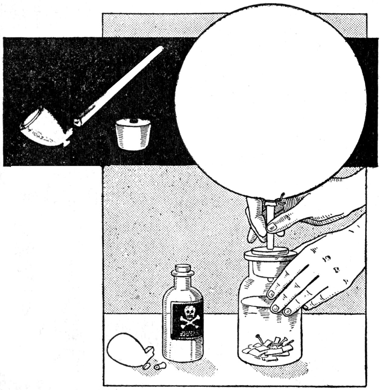
Apparatus for Filling Toy Rubber Balloons with Hydrogen Gas to Make Them Fly to a Great Height
Any boy can easily convert a toy rubber balloon into a real flier by constructing the simple device shown in the illustration for filling it with hydrogen. Procure a clay pipe and break off the stem near the bowl. Bore a hole in a cork, or preferably a rubber stopper, selected to fit some bottle and insert the smaller end of the pipestem in the hole. As the stem tapers, if the hole has been made for the smaller end, a tight fit is assured by simply pressing the stem well into the cork. Tie the open end of the stem on the balloon tightly over the larger end of the pipestem, and have ready a thread to tie the stem of the balloon when it is filled.
Procure from a local drug store 1 oz. of hydrochloric acid. Place some nails, or better still, a few strips of zinc, in the bottle and cover them with a little water, then pour a small quantity of the hydrochloric acid into the bottle and assemble as shown in the illustration. In a few minutes hydrogen gas will be given off, and if the joints are tight, the balloon will begin to fill. After it has expanded as much as it will stand without breaking, tie the end with the thread, and cut off any parts of the mouthpiece that may weigh it down. If sufficient gas has been passed into the balloon it will rise to the ceiling. Balloons filled in this manner have risen to a height of several hundred feet.
Caution: Do not allow the hydrochloric acid to come in contact with the skin or clothing, as it may cause frightful burns. Do not under any circumstance fill the balloon near a flame or allow fire to come near the bottle.—Contributed by Ralph C. Jenkins, Manchester, Vt.
There seems to be a feeling among mechanical and electrical experimenters that there is something mysterious about the process of wood finishing, and often one may see a really fine piece of apparatus spoiled by mounting it on a shellacked baseboard. I have found that it is a very simple matter[31] to produce almost a piano finish on all woods, even those as soft as poplar, in the following manner. Quick-drying wood dyes should be avoided. Simply rub down a piece of ordinary water-color cake into some plain water and apply freely with a rag, rubbing it in well. Any color may be obtained in this way, but if this is not convenient, use an oil stain made quite thin with turpentine. Next apply a thin coat of shellac, which should be sandpapered when it is dry. A coat of ordinary varnish is then applied, and when this is thoroughly dried, rub lightly with fine steel wool. One coat of varnish may be sufficient, although several coats will produce a richer finish. Rub the last coats down well with an oily rag dipped in some abrasive material, such as tooth powder or metal polish, and finish with a simple oil rub. A beautiful, soft, transparent effect may be obtained in this way on very ordinary woods. Any open-grained woods, such as oak, must be filled with a paste filler after staining.—Contributed by John D. Adams, Phoenix, Ariz.
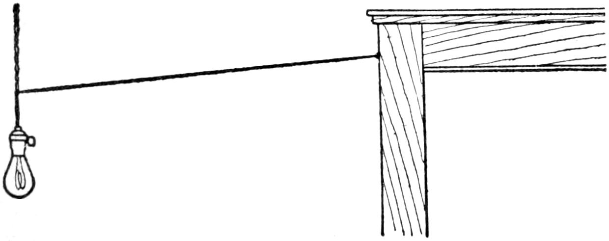
The Cord Fastened to the Door Casing is Easily Located and Followed to the Lamp
A simple device for locating a droplight can be had by putting a nail or screw eye into the side of the door casing, high enough to clear persons passing under it, but within easy reach of an uplifted hand, and running a cord from it to the light. It is not difficult to locate the cord attached to the casing and to follow it to the light.—Contributed by H. S. Craig, Rushford, Minnesota.
¶If kerosene oil is used when drilling, reaming, or turning malleable iron, it will make the work much smoother.

A Copper Wire Wrapped around and Soldered to a Straight Rod for a Lead Screw
Often in experimental work a long, narrow, parallel screw is desired for regulating, or moving, some part of the apparatus in a straight line. A simple way of making such a screw is to tin thoroughly a small straight rod of the required length and diameter. After wiping off all the surplus solder while it is yet hot, wrap it with a sufficient length of bright copper wire and fasten the ends. This wire is then securely soldered in place by running the solder on while holding the screw over a blue gas flame. To make the solder run freely, brush frequently during the heating with a small mucilage brush dipped into the soldering acid. An even pitch can be secured by winding on two wires side by side at the same time, the second one being unwound before soldering.
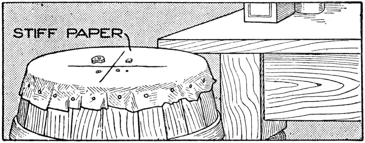
The Paper Stretched over the Barrel Top was Cut after Feeding the Rats on It for Some Time
A suburbanite successfully trapped a bunch of rats by stretching a piece of stout elastic paper on the top of an open barrel. Spreading food on this paper he allowed it to remain until the suspicions of the rats were allayed, then he cut two right-angled slashes in the paper with a razor. Next morning he found seven of the pests in the barrel.
[32]
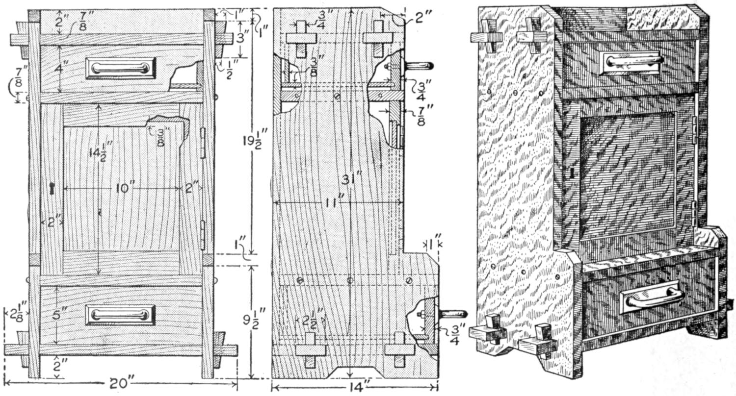
The Smoker’s Cabinet Makes an Attractive Addition to the Furniture of a Den, and should be Made Up and Finished to Match Other Pieces of the Room
This design, when completed, takes up a wall space 20 in. wide by 31 in. high, and extends out 14 in. The material necessary for it is as follows:
| 2 | sides, ⁷⁄₈ by 14 by 31 in. |
| 1 | back, ³⁄₄ by 14 by 28¹⁄₈ in. |
| 1 | bottom, ⁷⁄₈ by 14 by 20 in. |
| 1 | top, ⁷⁄₈ by 10¹⁄₄ by 18³⁄₄ in. |
| 1 | bottom shelf, ⁷⁄₈ by 10¹⁄₄ by 14 in. |
| Door: | |
| 2 | stiles, ³⁄₄ by 2 by 14¹⁄₂ in. |
| 2 | rails, ³⁄₄ by 2 by 10 in. (not including tenons, if such are desired). |
| 1 | panel, ³⁄₈ by 10³⁄₄ by 11¹⁄₄ in. |
| Upper drawer: | |
| 1 | front, ³⁄₄ by 4 by 14 in. |
| 1 | back, ³⁄₈ by 3¹⁄₄ by 13¹⁄₂ in. |
| 2 | sides, ¹⁄₂ by 4 by 9⁷⁄₈ in. |
| 1 | bottom, ³⁄₈ by 9⁵⁄₈ by 13¹⁄₂ in. |
| Lower drawer: | |
| 1 | front, ³⁄₄ by 5 by 14 in. |
| 1 | back, ³⁄₈ by 4¹⁄₄ by 13¹⁄₂ in. |
| 2 | sides, ¹⁄₂ by 5 by 12⁷⁄₈ in. |
| 1 | bottom, ³⁄₈ by 12⁵⁄₈ by 13¹⁄₂ in. |
| 1 | piece for keys, ³⁄₄ by 2¹⁄₄ by 6¹⁄₄ in. |
| 1 | pair hinges. |
| 2 | drawer pulls. |
| Screws and nails. | |
In constructing the cabinet, the outer frame should first be made. The sides can be laid out and cut to the desired design. The top and bottom crosspieces should then be squared up, and the tenons cut as shown, the bottom tenons extending farther, to balance the design. The top is set in ³⁄₄ in. from the back edge. Holes should be marked and cut for the ³⁄₄-in. keys, after which the four parts may be assembled, and suitable keys driven in place. The back for the cabinet is made from ³⁄₄-in. material, squared up to fit between the sides, and be flush with their top edges while resting on the bottom crosspiece. It can be fastened in place with nails. The top and bottom pieces of the cabinet proper can then be made, and secured in place with round-head screws, after which the door may be made and fitted. The stiles and rails of the door should be rabbeted for a ³⁄₈-in. square groove, to hold the panel in place. The frame can be made sufficiently strong, if properly glued and held together with dowel pins passing through the stiles into the rails. If it is desired to fasten the frame with tenons, an extra amount must be added to the length of the rails given in the stock list. The panel should not be glued in place, as the shrinkage of the wood will cause it to crack.
In making the drawers, the front should be rabbeted for a groove to fit the drawer bottom, and sidepieces can be fitted and nailed in place. These should be rabbeted for grooves, into which the bottom and end pieces fit.
If the cabinet is finished in mission style, or fumed oak, hammered copper or brass hinges and drawer pulls will go well with the general appearance of the design.
[33]
Skis and Ski-running
Running, Jumping and Climbing
By Stillman Taylor
Part II
Before the beginner makes the attempt to ski, he should see that his complete outfit is perfectly suited to his purpose. The shoes should be nicely adjusted to fit snugly between the metal toe plates of the binding, and new holes should be punched in the straps wherever needed to adjust the harness snugly and comfortably to the feet. Many of the positions required in executing the various turns and swings may be practiced at home, that the novice may get some idea of the correct position of the feet and body assumed by expert skiers. For the initial practice outside, it is a good plan to select a frosty day when the snow is old and settled by the wind. This will introduce the novice to the sport under favorable conditions, while if the first trials are made shortly after a heavy snowfall, or upon a mild day when the snow is thawing, only discouragement will be experienced. Begin with one stick—or two if timid—and pick out an easy-sloping hill with a gradual run to the level ground. A few scattered trees and rocks will do no harm, for it is a good plan to learn how to avoid them from the beginning.
This and the correct manner of standing on skis are easily mastered if the beginner will but remember that the weight of the body should rest largely upon the advanced foot without bending the body at the ankle too much, or raising the heel from the ski. This is the correct position to assume when standing for a rest and for sliding, and this as well as turning should be practiced on the level. To make the kick turn, simply raise the point of the ski until the heel rests on the snow, as shown in Fig. 1. Swing the ski around by turning the point out and back until the two skis are point to heel, as shown in Fig. 2. When this, the most difficult position of the three, is assumed, raise the point of the other ski as high as convenient to avoid tripping, keep the heel down and swing the ski around over the heel of the other until both are facing in the same direction, as shown in Fig. 3. A little practice will make it possible for the novice to turn quickly, and if all turns are made with the advanced foot, when practicing on the level, no trouble will be experienced later on in attempting to turn on a steep slope. The stick is really indispensable for this practice, and while two may be used, the single stick will be found assistance enough for any active person.
When skiing on level ground the correct movement is rather more of a slide than the motion used in walking or skating. The body is thrown forward on one ski and the slide is made with both feet, most of the body weight being thrown on the advanced ski, while the rear foot is slid forward without stopping the forward travel, as shown in Fig. 4. The expert skier moves forward in long gliding steps without raising the ski, but bending the knees slightly to slide the ski ahead. The feet should be kept as close together as possible to make a narrow track and the stick used to lengthen the slide. At the beginning it is a good plan to endeavor to make a long slide with each advancement of the foot, rather than strive to take long[34] steps. The speed of level running depends, of course, upon the condition of the snow. On hard, well-packed snow, sliding is easiest and greater speed obtained, while in deep and soft snow less speed is the rule. When skiing on the hard snow of a road, four miles an hour is the average speed, and for average level running, the skier will cover about the same distance as when walking along a good path.
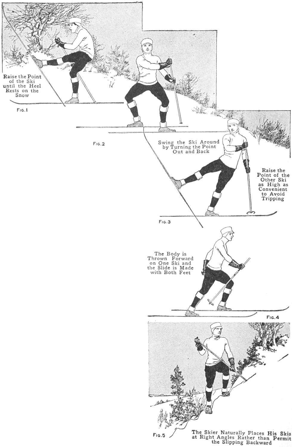
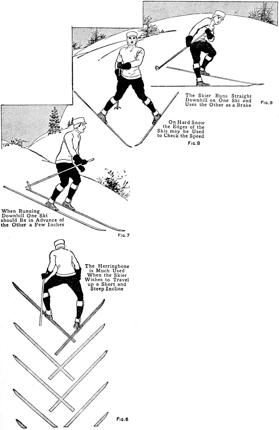
| Fig. 1 Raise the Point of the Ski until the Heel Rests on the Snow |
Fig. 9 The Skier Runs Straight Downhill on One Ski and Uses the Other as a Brake |
||||
| Fig. 2 Swing the Ski Around by Turning the Point Out and Back |
Fig. 8 On Hard Snow the Edges of the Skis may be Used to Check the Speed |
||||
| Fig. 3 Raise the Point of the Other Ski as High as Convenient to Avoid Tripping |
Fig. 7 When Running Downhill One Ski should Be in Advance of the Other a Few Inches |
||||
| Fig. 4 The Body is Thrown Forward on One Ski and the Slide is Made with Both Feet |
Fig. 6 The Herringbone is Much Used When the Skier Wishes to Travel up a Short and Steep Incline |
||||
| Fig. 5 The Skier Naturally Places His Skis at Right Angles Rather than Permit the Slipping Backward |
|||||
When traveling uphill, the regular sliding gait will suffice if the slope is gradual, but when a steep grade is encountered and the ski slips backward, the skier stands quite erect, raises the point of his ski about 3 in., and slaps it down smartly, without pulling it backward or making any attempt to push his body forward with the stick. This slap of the ski makes the smooth surface of the runner adhere better than when the runner is slid forward in the usual manner. If the hill is very steep, the skier will naturally place his skis at right angles rather than permit the slipping backward. This is known as “side-stepping,” and is shown in Fig. 5. In doing this, the heel of the ski must be raised clear of the snow and the upper foot lifted uphill, then the lower foot brought up to the last step of the upper foot, hence it is extremely tiring for other than a short distance.
A variation of this movement, which is known to skiers as the “half side step.” and which is made by advancing the foot with the legs somewhat wider apart, and the skis placed at not quite so acute an angle with the hill, is more useful when climbing the ordinary steep grade and is far less laborious. If the skier knows how to handle his implements,[35] side-stepping may be done backward when necessary.
The “herringbone” is another step which is much used when the skier wishes to travel up a short and steep incline. This step is made by stretching the legs rather wide apart and pointing the toes out, as shown in Fig. 6, at a decided angle, so that the knees are bent inward and the inside edges of the skis cut into the snow. A variation of this is the “half herringbone,” the skis being turned out at a less acute angle. These special steps for special purposes are all useful now and then in mountain climbing, but when a long distance is to be covered, the skier will conserve his energy by mounting the hill in a zigzag fashion rather than attempting to climb straight up. The track of the skier will then resemble the course of a boat tacking through a narrow inlet against a head of wind, and while more ground is covered than when going straight up the steepest part of the hill, progress is faster and much hard work is avoided.
When running straight downhill, one ski should be in advance of the other a few inches, and the skis must be held quite close together so that they touch, or nearly so, as shown in Fig. 7. To make a narrow track, most expert skiers hold the knees together with the back knee slightly bent. However, the body should be perfectly and easily balanced. This is done, more or less, intuitively, by beginning the run with the body thrown on the advanced foot, and when full speed is attained the weight automatically shifts to the rear foot. The novice will find it difficult at first to keep the skis together, there being an almost uncontrollable desire to separate them to[36] gain a better balance. A good track will come with a little practice, but if the skis are too short, or made without a groove, even an expert would be compelled to keep his feet a trifle apart and make a double track in order to keep from falling.
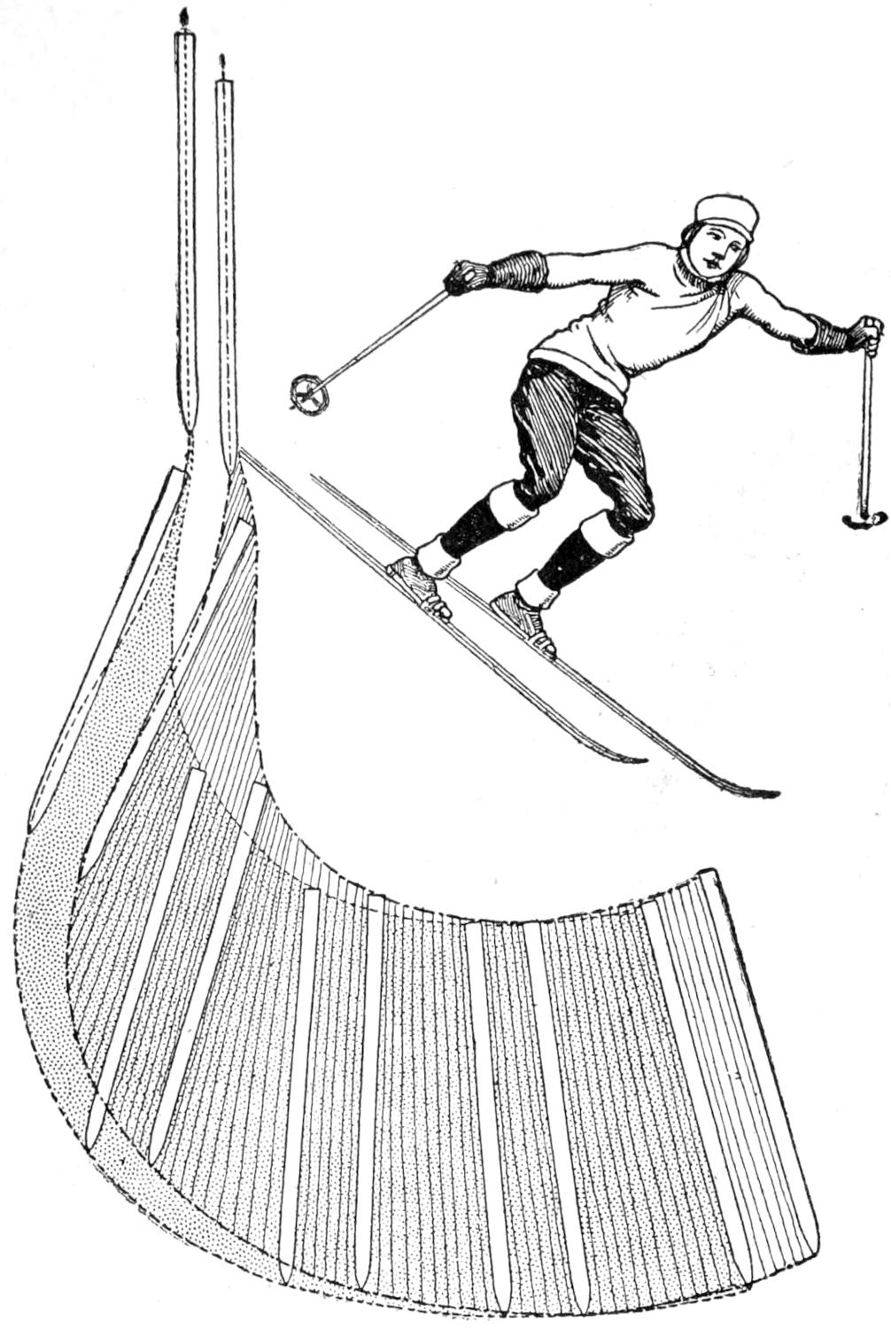
Fig. 10
The Christiania Swing is Accomplished
by Pressing with Both Heels at
the Same Time While the Stick
Digs Well into the Snow Above
When making the start preparatory for coasting downhill, the novice may, if the slope is moderately steep, face in the desired direction and assume the proper position by supporting himself with the stick. On most very steep slopes, where the best coasting is to be had, this is quite out of the question, and the skier must step around quickly by moving the lower ski first. This will be somewhat difficult to do until the novice gains more confidence, which will quickly come after a little practice, and it is a good plan to practice starting from the slope without the aid of the stick to anchor the body. Owing to the fact that the skis do not reach much speed at the start of the coast, even the slow novice will have plenty of time to make the turn and face in the right direction before much speed is attained. A comparatively crouching position, secured by bending the knees and the body at the waist, will much lessen the liability of a fall forward. This position enables the skier to control the balance of his body with more certainty, and especially when coasting on a hill where patches of ice, or crusted snow, and soft spots of unpacked snow are encountered, a condition usually found wherever skiing is enjoyed. When coasting, the stick, or sticks, should be firmly grasped at the upper end with the looped thong, or strap, over the wrist, and the end dragging behind. Balancing is done entirely at the waist, and for straightaway running, the weight of the body will rest largely upon the rear ski. The long running surface of the ski will carry the skier over many bumps and hollows without disturbing the balance of the body or causing a fall, providing the novice does not lose his nerve. It is necessary to practice on rough and uneven ground if the skier desires ever to attain much expertness, and plenty of falls must be expected, but not dreaded by the beginner. A fall on skis is by no means fraught with danger, and one may fall with impunity providing all muscles are relaxed. Many beginners find falling the easiest manner of stopping, but this should not be necessary, providing the hints given are well understood and practiced. However, the novice should have no fear of falling if he wants to become proficient on skis, and to offset any timidity, which so very often causes the novice to lean backward and fall in this direction, it is a good plan to lean well forward to check this natural tendency. Getting up after a fall is easily enough managed if the head is pointing up the slope, but when the position is reversed much floundering is necessitated. It would seem that this would be obvious to all, yet the majority of beginners often forget it altogether.
Braking with the stick is only effective when the body is properly balanced, and the stick is kept well forward and as nearly vertical as possible.[37] Straddling the stick, sitting upon it, or leaning backward on it held at an angle, are slovenly methods which every novice should avoid.
The “snowplow” is most largely used by all good skiers for braking, stopping, and turning. This is accomplished by stretching the legs wide apart and at the same time turning the toes in as much as possible, thus presenting the side of the ski to the snow and retarding the speed. Aside from straddling the legs wide apart, the novice will have no trouble in learning this useful knack. For the first practice, pick out a fairly steep hill road, or a hillside where the snow is old and not soft. Begin the run as for coasting, and when good speed has been attained, spread the legs wide apart, turn the toes in and endeavor to control the speed with the skis rather than depend upon the stick. On hard snow the edges of the ski may be used to check the speed, but on ordinary soft and well-packed snow, the runner may be kept quite flat. This is well shown in Fig. 8.
The knack of “stemming” is a variation of the snowplow, inasmuch as the skier runs straight downhill on one ski, and turns the heel of the other ski outward and downward and uses it as a brake, as in Fig. 9. This is a very useful movement, and is largely used when coasting down steep slopes, and when one has learned the knack of it, stemming will serve for braking and steering, and is useful for stopping by turning the skiing course uphill. To earn it, select a steep hillside, coast down at an angle, with the feet a trifle part, and endeavor to retard the speed with the stick and turn the heel of the lower ski outward. This makes the turn and the skier faces uphill and comes to a stop. By turning the heel of the lower ski outward and the heel of the upper ski inward, the skis will travel downhill with a sort of snowplow movement. When practicing these movements, the beginner should endeavor to use the stick as little as possible and learn to depend upon the skis for controlling the speed.
The “side slip” is useful on steep slopes, and is done by turning the skis so that the runners are at a decided angle to the course traveled. This affords the maximum braking by the skis alone, and is especially effective when combined with the braking done with the stick. Side-slipping may, of course, be done while the skier is traveling forward, by keeping the skis close together so that the edges almost touch. While this movement checks the speed in much the same manner as stemming, side-slipping is less tiresome, since the weight of the body gives the required braking effect, while, in stemming, the muscles are called upon to keep the heel pressing outward.
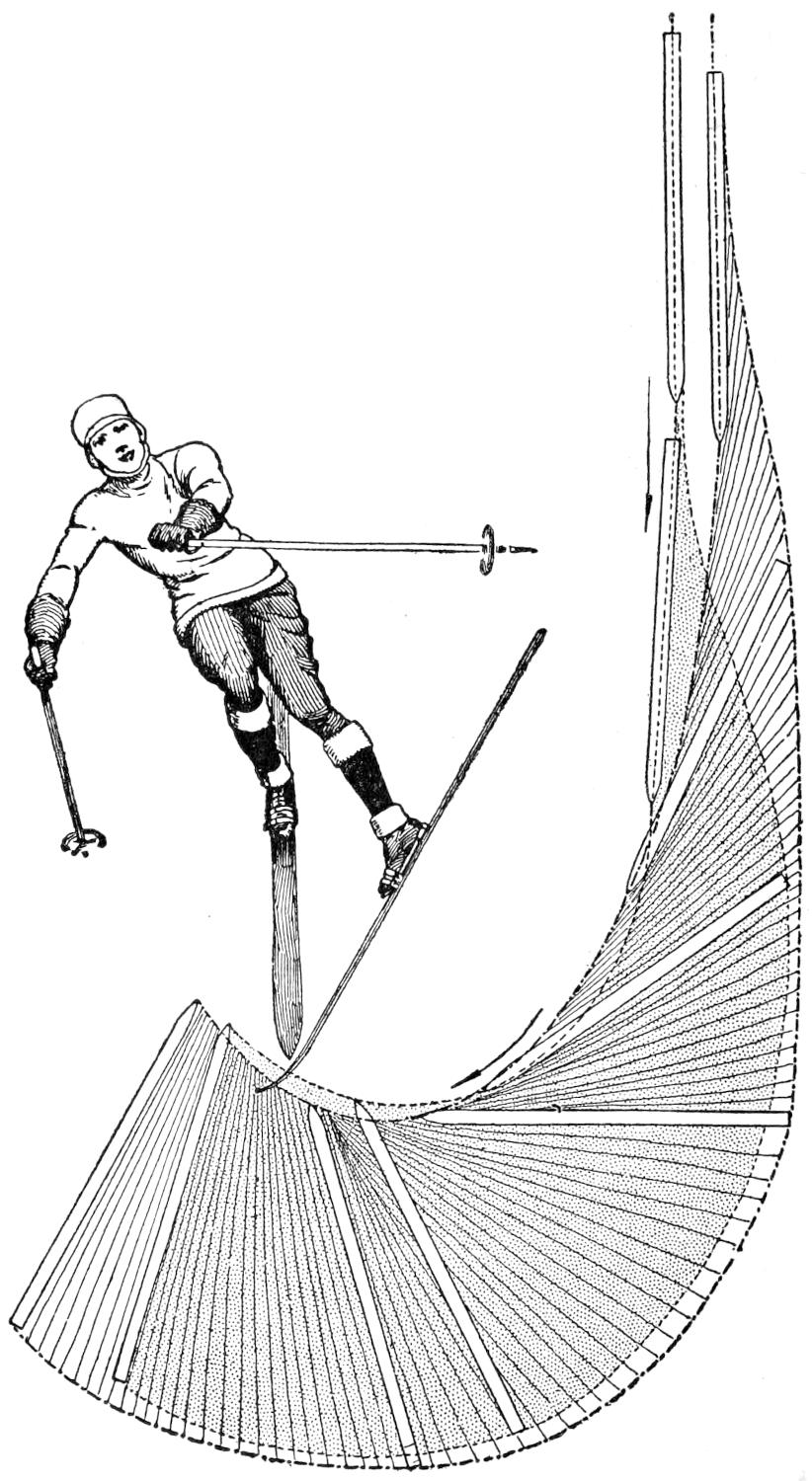
Fig. 11
The Swing is Made upon
One Ski Instead of
Using Both as in the
Christiania Swing
Closely akin to side-slipping is the Christiania swing with the stick, which is accomplished by pressing with both heels at the same time, while the stick digs well into the snow above. This variation of the side slip is easily done, and the skier is turned sharply[38] uphill to come to a quick stop. When a sharp hill is met with, that is considered a bit too steep to take straight, this swing with the stick may be made by taking a zigzag course down grade steering clear of any obstacles by snowplowing, stemming, or side-slipping; and turning the corners, or “tacking,” by making use of the Christiania swing and the stick, as shown in Fig. 10.
The “S”-turn may likewise be used for turning corners, without the necessity for stopping to make the ordinary kick turn. A good way to learn this useful movement is to run straight downhill in a snowplow position, reduce the speed to a comfortable walking pace with the stick, and stem with the ski. If this is done with the right ski, the “S”-turn is made by throwing practically the whole weight of the body on the right ski, at the heel, and pressing it outward while the stick is carried ahead and below the skier. If the heels are kept well apart, and the toes close together, the skier will have no trouble about swinging around in a curve and be off on the other tack. About the only difficulty in making the “S”-turn is the position of the body, which must be thrown somewhat out and away from the hill. To the novice this at first seems to invite a fall, but a few trials will soon prove that the weight of the body must be thrown on the foot which circles on the outside of the curve, hence the apparently unnatural position of the body is essential for a good turn. By bringing the stick well forward and downhill, the skier uses his staff as a pivot upon which the turn is made.
The Christiania swing, made without the stick, is a favorite with expert ski runners when running on rough and steep ground and is a good way of stopping. The swing may be made both to the right and left. To make it to the right, keep the skis close together, the right a trifle in advance, with the weight of the body equally on both feet and with knees slightly bent. Now throw the weight more forward and upon the toes, while the heels are carried forward and outward to the left. The body must lean to the right—the direction in which the swing is made—and twisted somewhat at the waist; and the sharper the turn, the more the body must lean sideways to keep the balance. The swing to the left is made in the, same fashion, only the left ski should be a trifle advanced and the body thrown to the left.
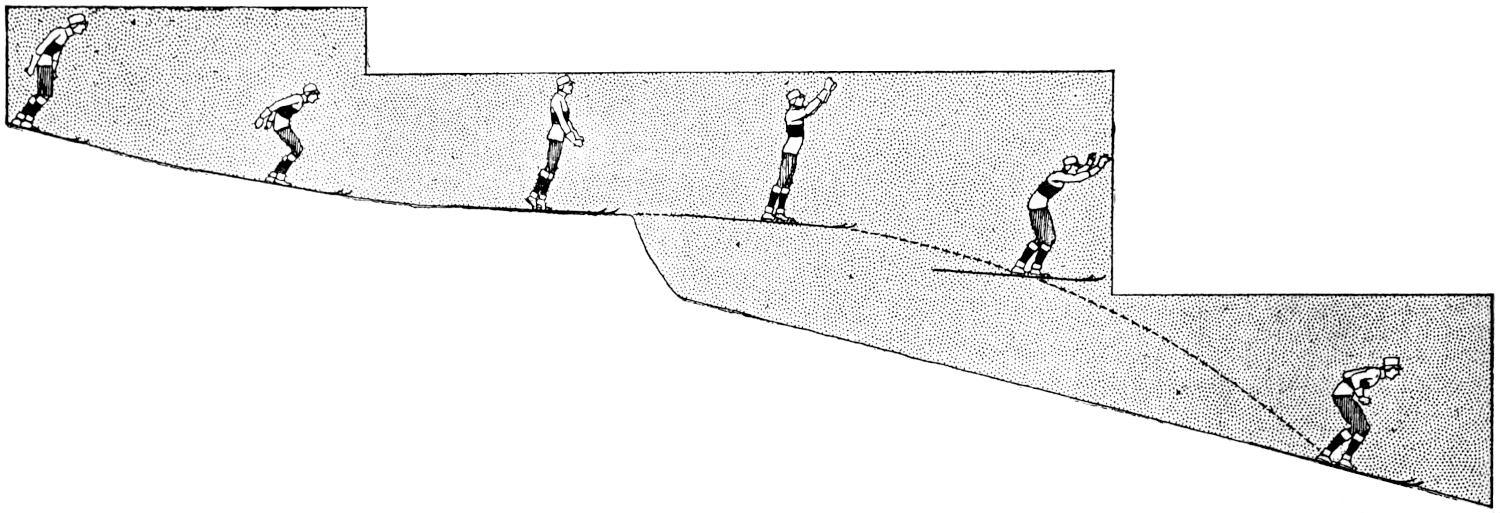
Fig. 12
To Make the Jump the
Skier Assumes the Easy
Position Required for
Coasting Downhill
The Telemark swing is more difficult to master than the Christiania swing, because it is done on one foot, or ski, instead of using both, and as it is less powerful than the latter, it is of far less use for stopping. To make the Telemark swing to the right, assume the regular position for downhill coasting, and, advancing the left foot, turn the ski so that it rests on its edge as when making the snowplow, throw the body to the right and lean in toward the slope to keep the balance. To make the swing to the left, advance the right foot, turn the body to the left and lean as before. This is shown in Fig. 11. The Telemark turn is, in fact, made in the same manner as stemming, and the sharpness of the swing rests altogether upon the quickness with which the heel is thrown outward and the body turned in the direction the skier desires to swing. The swing is made upon one ski, and the key to the whole swing is the knack of raising the heel of the other foot off its ski until it rests upon the toes. That this is hard to do goes with the telling, and the novice should first acquire the knack of balancing[39] by running straight downhill with the weight thrown on one foot. When this can be done, and not before then, the skier is ready to practice the turn. The Telemark swing, like all other turns, is easily acquired at slow and moderate speeds, and becomes more and more difficult to make as the speed is increased and the turn is made more sharply and quickly.
Jumping on skis is one of the most exhilarating winter sports, and it is a pity that it is not more popular wherever a medium-heavy fall of snow occurs. While touring on skis across a hilly country, there will be many natural jumps to encounter, for drifts, stumps, rocks, and other rises in the ground, when well covered and padded with snow, make good jumping-off places. While but a few skiers may have attempted such high leaps as the famous Holmenkollen, Fiskertorpet, or Foldberg, all who have done much ski running have done a little jumping, since, when running downhill, an unexpected dip is often encountered, and a rise in the ground causes the skier to leave the ground for a short distance and alight several feet below. Doubtless the skier has enjoyed the flying-like sensation of this brief moment, and very likely he has climbed the hill to repeat the jump. Moreover, this has very likely demonstrated that the distance of the jump depends upon the height of the dip, the speed of the skier passing over it, and likewise upon the spring of the body on the take-off. In making a jump of any height, the take-off may be level, pointing up or even downhill, and constructed with framework extending out from the hillside, or consist merely of a large boulder, or a pile of logs, well padded with snow. The height of the slope chosen will, of course, regulate the distance of the jump, and the place where the jumper alights should be fairly steep, since, if the skier lands upon a level place great difficulty will be experienced in keeping the balance, therefore the usual jumping hill, where jumping competitions are held, is provided with a 30°, or steeper, landing place, and this merges gradually into the outrun, or slope, connecting the hill with the level ground below.
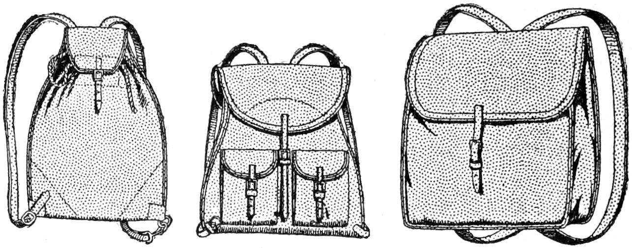
Fig. 13
Each Member of the Party should be Provided with
a Ruck Sack of Good Capacity
For the safety of the skier, the snow should be firm but not icy or hard, and this is easily done by packing the snow down well by means of the skis. A good, thick padding of snow is of course essential, and a thickness of 2 ft. is really needed at the landing place and at the take-off. In our more northerly sections, plenty of snow usually falls, but wherever a few sportsmen get together, it is an easy matter to shovel sufficient snow to prepare a good and safe jumping hill.
To gain confidence and acquire some useful experience in jumping, the novice should practice leaping from a 2-ft. rise and gradually increase the height of the take-off by piling more snow upon it to increase its height. One or two packing cases firmly placed upon a smooth, steep hillside, and well padded with 2 ft. of well-trodden snow, will make a nice take-off. For the beginning the take-off may point slightly downhill or be fashioned level, and as the skier becomes more proficient, snow may be added to the edge so that the take-off will send the jumper well up into the air.
The knack of jumping is nothing more than balancing the body upon alighting, and the steeper the landing place the easier it is to keep the balance. To make the jump in good form, the skier assumes the easy position required for coasting downhill, as shown in Fig. 12. When within a dozen yards of the take-off the body is lowered until the skier is in a crouching position with the arms extending back as in the act of jumping. Arriving within a couple[40] of yards of the dip the body and arms are thrown forward, which transfers the weight of the body upon the toes, and the body is straightened up and the arms are raised not unlike the wings of a bird, to keep the perfect balance of the body. The straightening up of the body, known to skiers as “the sats,” is the leap proper and must be timed so that the body assumes an erect position when the jumper is not less than 12 ft. from the edge of the take-off. The beginner will invariably jump too late, but after a little practice, and profiting by numerous mistakes, the take-off will be timed correctly. Alighting after a jump is best done by advancing one ski a trifle to keep the balance, and bending the knees a bit to lessen the impact. The jumper ends with the Telemark or Christiania swing.
When taking tours of any length on skis, each member of the party should be provided with a ruck sack of good capacity. That of the expanding type, made with two outside pockets, and with gores at the sides, is a good, sensible pack. It should be made of 8-oz. waterproof khaki and fitted with shoulder straps of good width, to prevent chafing the shoulders. Leather ruck sacks are sometimes used, but are heavier in weight and more expensive but no better. One member of the party should carry some kind of repairing outfit, consisting of an awl, a length of leather thong, a few spare straps and a stout cord, or string. These sacks are shown in Fig. 13.
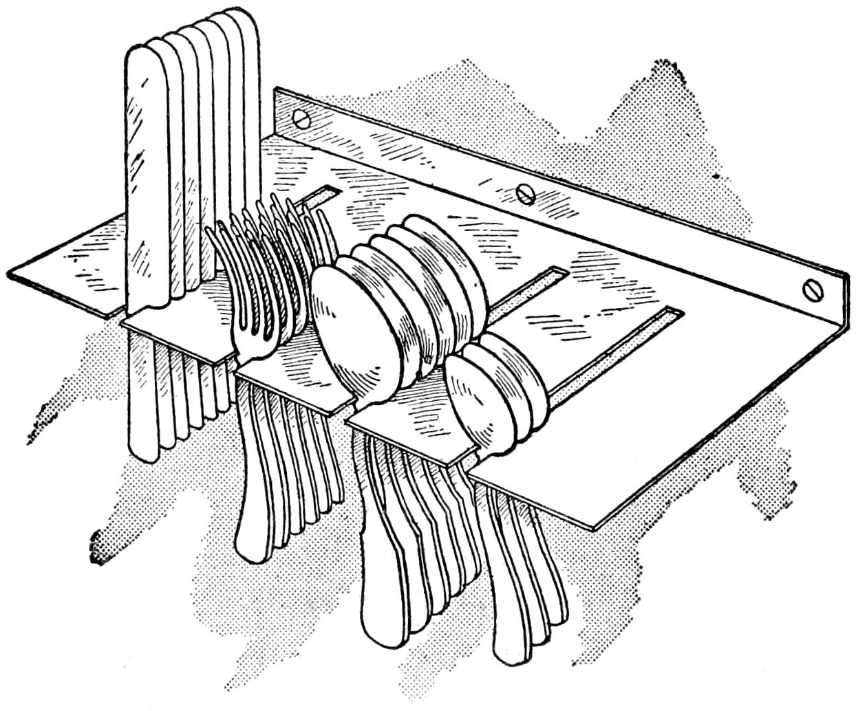
The Holder Keeps the Cutlery in a Position for Easy Selection and Grasping
The holder is made of a piece of sheet copper of sufficient thickness to support the number of pieces of cutlery used. The piece is notched to admit the different pieces, and its back edge is bent at right angles to provide means of fastening it to a support, a wall or the back of the kitchen cabinet. It will save space, as well as time, since it is much easier to grasp one of the articles when wanted than if they are kept in a drawer.—Contributed by L. E. Turner, New York City.
In looking forward to the enjoyment that may be had in the spring, it is well to prepare and overhaul the fishing apparatus or the shooting equipment. In doing so, it may be necessary to make a joint for the fish rod or perhaps a rod for the gun. These can be easily cut if they are sized and run through holes made in a piece of thin metal as follows: Make several holes of the desired sizes in a steel plate, and ream them out with a rather dull taper reamer, so as to leave a bur on one side. This bur should be filed down almost level with the surface of the metal, leaving the edges flat and sharp. If a rod of wood from which the article is to be made is put in a hole and drawn through from the opposite side to the bur, a nice round rod will result. As the rod becomes smaller, use a smaller hole until the required diameter is obtained. A saw plate that is not too thin is about the proper thing to use for the steel plate. It will be necessary to draw the temper to make the holes, but it is not necessary to retemper it after the holes are made.
¶Celery keeps well in a small box of dry sand.
[41]

The sled is built low and wide so that it will not tip easily. The skis, or runners, are cut 10 ft. long and 6 in. wide, from 1-in. ash boards that are straight-grained. At the points where the curve is to be formed, plane off about ¹⁄₄ in. on the upper side, but do not plane off any at the very tip end. This will allow the skis to be more easily bent. If it is not handy to steam the skis, put them in boiling water, and be sure that at least 1¹⁄₂ ft. of the points are covered. Provide a cover for the vessel, so that only very little steam may escape. Let them boil for at least one hour. A good method of bending the points is shown. When the skis are taken from the water, put them as quickly as possible in the bending blocks, side by side, and bend them with a slow, even pressure. Weight the extending ends and leave the skis in the blocks 8 or 10 hours to dry. Sharpen the points after they are bent.
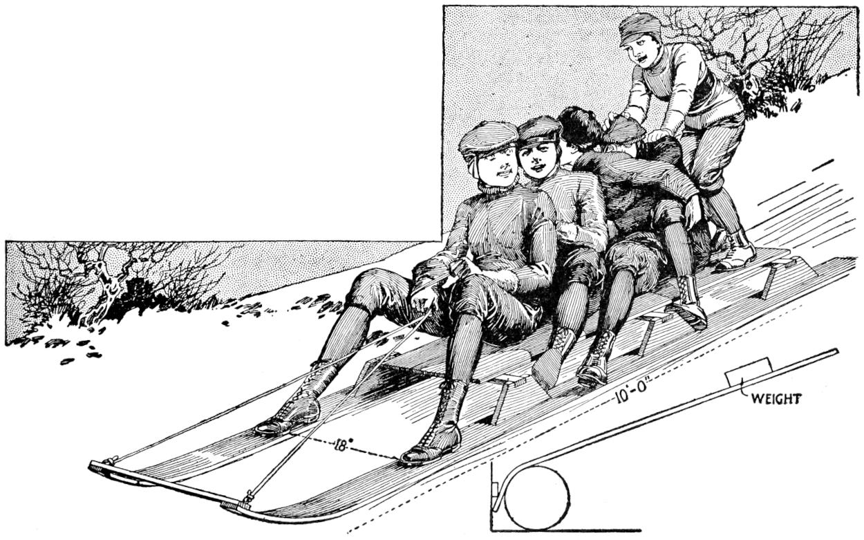
The Runners are Shaped Like a Ski and are Joined Together with Knees for the Top Board
The sled will run easier if the skis have a slight rocker curve. To make this curve, have the center block 6 in. while the two end blocks are 5¹⁄₂ in. high. A ¹⁄₄-in. flat-head bolt is run through the ski, the block, and the cross strip. The holes are countersunk in the surface for the heads of the bolts. The top is made of three 6-in. boards, fastened to the crosspieces. It is a good plan to brace the tips of the skis with a 2-in. strip.
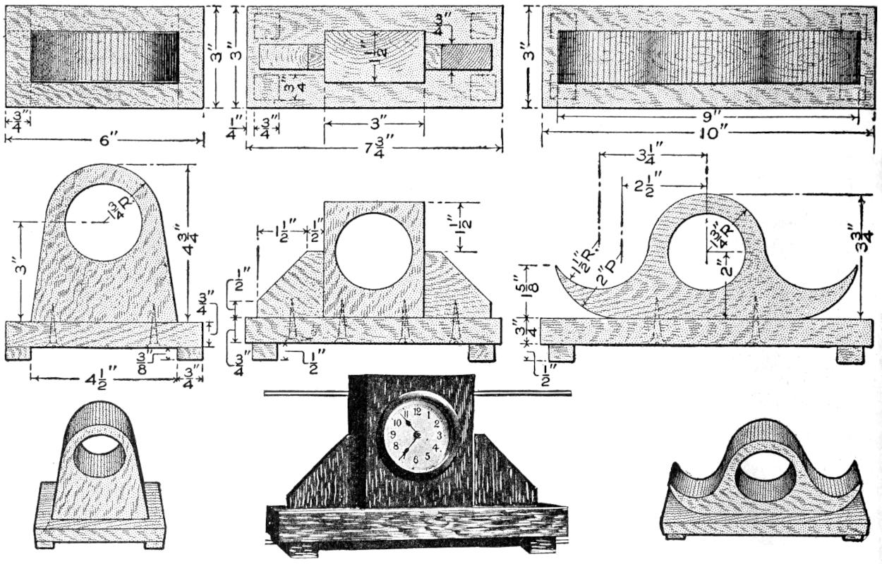
An Ordinary Alarm Clock Mounted in a Wood Base Made in Elaborate Designs to Resemble a Timepiece of High Value; yet Inexpensive to Make
Three designs of clocks are shown, which can be easily made in oak, or other wood, that will match other furniture. The sizes of the pieces required are given by the dimensions in the drawings.
The clock is a matter of choice. Prices in most stores range from 75 cents up and the works are of the ordinary alarm-clock variety. After selecting the clock the small legs as well as[42] the back plate are removed. The hole cut in the wood for the clock must be a snug fit, and after placing it in position, the back plate is replaced.
The finish may be a wax or gloss, as desired, and directions for applying it will be found on the can containing the material.
A small portable galvanometer is one of the most useful instruments to the electrical experimenter. There are continually arising instances where it is necessary to test through and identify certain wires, for which purpose a small galvanometer and a dry cell are quite sufficient. For comparing the resistances by the well-known Wheatstone-bridge method, a galvanometer is, of course, indispensable. If the winding is made suitable, or by placing a shunt across the terminals to reduce the deflection, a small galvanometer will roughly indicate the current passing and thus enable one to compare his dry cells and eliminate the weak ones. Rough voltage comparisons may also be made by placing a resistance in series with the galvanometer.
For constructing this instrument, a good pocket compass, of about 2-in. diameter, must be procured. Prepare a neat little box with the four edges accurately beveled off. On the under side of this, carefully cut a channel, about ¹⁄₂ in. wide and 2¹⁄₂ in. long, to a depth that will bring the bottom of the slot within ¹⁄₈ in. of the top of the base block. Place two binding posts on the base, as indicated, and secure the compass in place with cement, or by two very small nails put through the bottom. If the glass cannot be removed, it will be necessary to solder the nail heads to the bottom of the compass box, after having carefully removed the lacquer.
The correct wiring will depend on the strength of the current handled. It is, however, very easy to get an idea of what the deflection will be under certain conditions by merely making a preliminary trial, after winding a few[43] turns of any magnet or bell wire at hand around a small piece of wood, and slipping the coil so formed into the slot on the under side of the base block. The winding may be from two or three turns of heavy wire up to several hundred turns of fine magnet wire, but after one or two trials, the maker will have no trouble in determining his particular requirements.
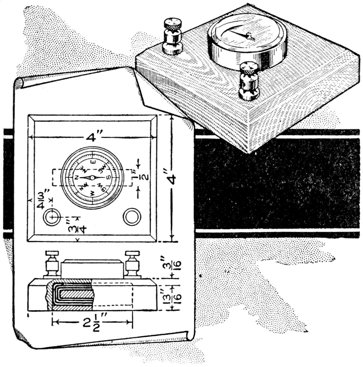
Galvanometer Made of a Compass Set on a Wood Base, with Coil and Wire Connections
The final coil should be wound lengthwise on a wood core, and the whole packed neatly into the slot. Connect up the ends to the binding posts, and then glue in a thin piece to hold the coil in place.
By drilling a small horizontal hole through the base, as indicated by the two dotted lines in the top view of the working drawings, and inserting a small bar magnet, ¹⁄₈ in. in diameter, or less, the instrument may be rendered independent of the earth’s magnetism and used without reference to the north point. Such a controlling magnet reduces the time required to bring the needle to rest after it has been violently reflected.
¶Woodwork about a house, when primed with white lead made quite thin in raw linseed oil, will never blister unless moisture gets back of it. Yellow-ocher priming will cause blistering at any time up to 20 years.
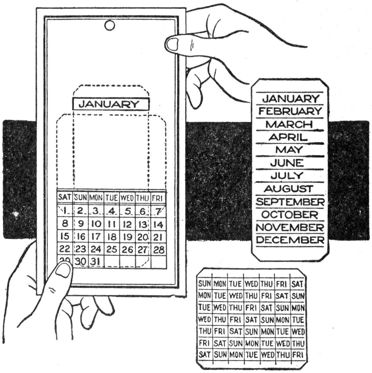
It is Only Necessary to Change the Sliding Pieces to Set the Calendar for Each Month
It is only necessary to set this calendar the first of each month, by sliding the insertions up or down, to get the proper month or week. The calendar, as it is shown, is set for January, 1916. Saturday is the first day and Friday the seventh, and so on. It is not confusing and can be read either by the day or date. If the day is known it will show the date, and if the date is known it will show the day. The illustration clearly shows the parts, which can be cut from heavy paper or cardboard.
A convenient small heater for heating liquids in experimental work, and even in making a hot drink where there is no gas, can be readily made from an ordinary oil lamp and a small round can, having a crimped-on head or bottom. The can should be of such diameter that the prongs of the lamp burner will hold it firmly in place. A hole should be made in the bottom of the can. It is then placed, upside down, on the lamp burner. If the top comes too far from the flame, cut off a strip around the edge.—Contributed by Clarence S. H. Anderson, Worcester, Massachusetts.
[44]
A Camp Chair Constitutes the Body of the Sled and the Legs are Equipped with Runners
On a smooth ice surface, or on hard snow, the sled shown will run easily, and a skater can push another with surprising speed by a light push on the shoulders while the rider rests his feet on the front of the runners. The sled is light, and it can be folded up and carried under the arm. It is also handy for putting on the skates, or for use in a crowded car.
Any camp stool will do for the main part of the sled. Holes are bored in the ends of the legs to receive the lugs on the runners snugly. If the builder is not equipped with a forge, a blacksmith will make the runners cheaply. The sliding surfaces of the runners are smoothed with a file.—Contributed by Thomas Lappin, Portland, Ore.
¶A column of water 27.6 in. will have a pressure of 1 lb. per square inch.
Some housewives advise a system of dry-cleaning for tinware for the reason that it insures a surface free from rust which is less liable to burn. Where washing is preferred, however, a little milk added to the water proves more satisfactory than either soap or soda, its peculiarly solvent effect upon grease obviating all necessity for hard scouring, which latter will wear the tin coating and gradually cause the article to become useless for holding food and more apt to rust into holes.—Contributed by J. E. Pouliot, Ottawa, Can.
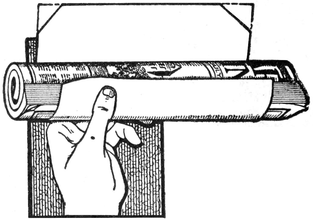
The Clipped Corners Prevent the Adhesive from Coming in Contact with the Paper inclosed
In using a homemade paper wrapper for mailing purposes cut a triangular section from each end of it before applying the paste or mucilage. This prevents the adhesive from oozing out at the edges and sticking to the paper it incloses. This also permits the easy withdrawal of the paper.
[45]
Having occasion to cut some grooves in a board and not being properly equipped for such work, I made the tool shown in the sketch. Although rather crude in appearance it will do good work if properly made. It consists of a handle, A, shaped to afford a comfortable grip for the hand, and a cutter, B, made of a short piece of hacksaw blade, clamped along the left side of the handle by the strip C, which is held with screws. A pin, D, driven into the handle and allowed to project about ¹⁄₁₆ in., prevents the blade from sliding back under the clamp. For guiding the blade, the arrangement F is employed. An extension, E, is nailed on the right side of the handle, and holes made near each end for two screws having round heads, such as may be obtained from discarded dry batteries. These screws are for securing the sliding stop F, which is a flat piece of hardwood with slots cut near the end for screws to pass through to provide for adjustment.
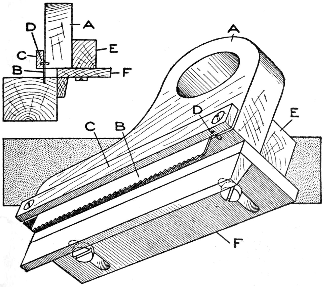
Two Slots are Made with the Cutter, and the Stock between Them Removed with a Chisel
In use, the guide F is adjusted until it is the desired distance from the cutter and then secured by the screws. The tool is handled like a plane, care being taken not to bear down too hard, as the cutter may bind and cause it to be pulled from the clamp. In cutting a groove, two slots are cut and the stock between them removed with a chisel.
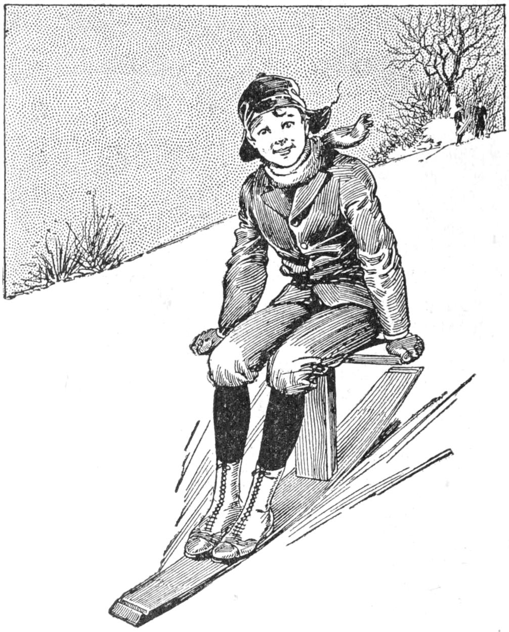
The Barrel Stave Has a Sufficient Curve to Make It Pass Smoothly over Hard Snow
Just an ordinary barrel stave, with a center post and a crossboard for a seat, makes a good one-runner sled. Select a good, smooth stave for the runner and securely fasten the upright, which is 1 ft. long, to it in the center. The seat is made of a board, about 1¹⁄₂ ft. long, nailed to the upper end of the upright.
Wishing to bake a nice loaf cake one afternoon for dinner, and finding that the fire in my range had gone out, I remembered an oven shown me at one time for use on a small gas plate, which consisted of a cover, a bottom piece, and a support for the pan. The thought came to me that with all my pots and pans I ought to be able to get some results by the combination of two pie tins, a cake pan, and a stew pan, and on trial it baked as fine a cake as anyone could wish.
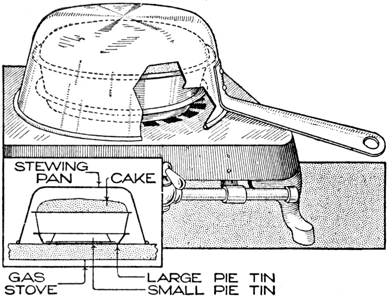
A Combination of Pie Tins, Cake Pan, and Stew Pan to Make Temporary Gas-Stove Oven
A small pie tin was placed in a larger one, as shown; on this was placed the cake pan filled with the cake batter,[46] and over the whole was placed the stew pan, which acted as a heat retainer or oven. A good hot flame was used at first, and was then gradually turned lower until the cake was finished.—Contributed by Mrs. Anna M. B. Romig, Allentown, Pa.
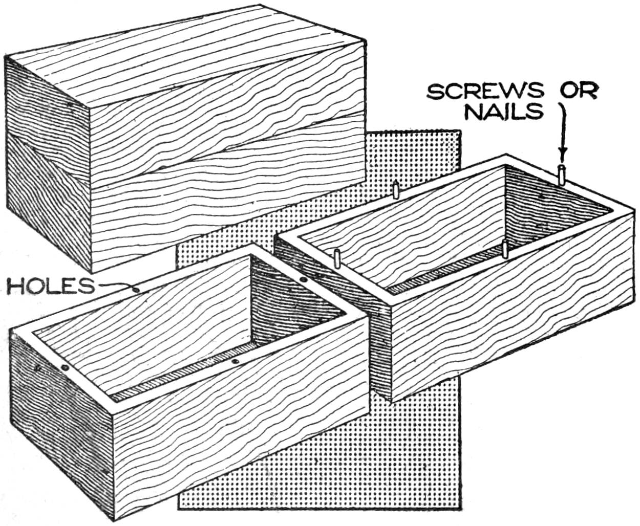
Box Cover Using Pins Instead of Hinges to Keep It in Place
Two ordinary boxes may be fitted together as one without using hinges, if nails or screws are inserted at points along the edges so that they will slip into holes bored at corresponding points in the edges of the other box. The nail heads or screw heads should be filed off or cut off after being placed in position.
¶All metal patterns should be thoroughly cleaned with a stiff brush having plenty of beeswax on it and dipped in powdered plumbago. Brush the pattern well, and it will draw easily and make a smooth casting.
A simple and convenient method of protecting a spool of thread, or dental floss, from collecting dirt and germs is shown in the illustration. A small glass jar, with a metal screw top, is procured, of such a size that it will easily accommodate the spool of thread desired to protect, with at least ¹⁄₈ in. clearance all around the edge of the spool. Procure a short piece of stiff wire, not more than ¹⁄₁₆ in. in diameter, and make a frame similar in form to the one shown. The center portion of this frame should be just a little longer than the spool, so that a small wood key may be placed through the eye formed in the wire and thus hold the spool firmly on the frame. The outside portions of the frame should be such a distance apart that they will rest against the sides of the jar and of such a length that they will reach from the bottom to the top of the jar when the lid is screwed down tightly. If these dimensions are observed, the spool and frame will remain in a fixed position in the jar.
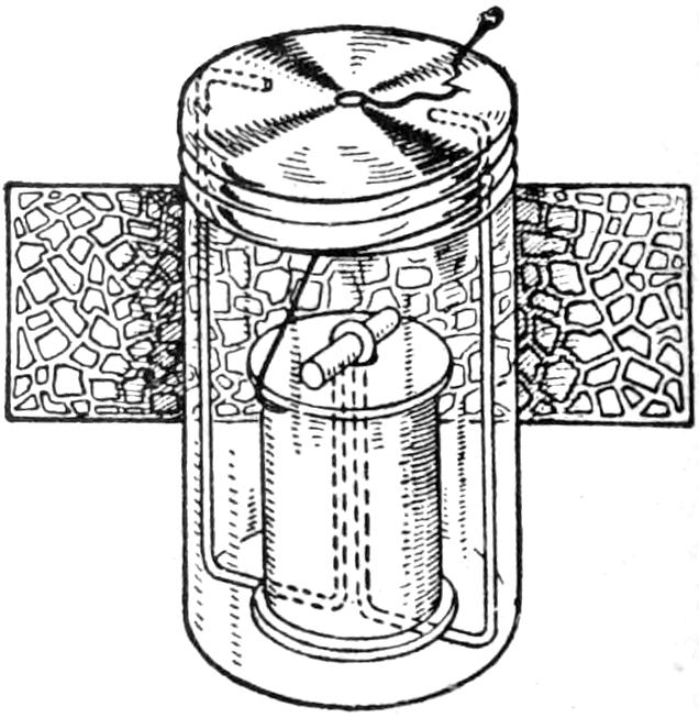
A small opening, just a little larger than the thread, is made in the center of the lid, through which the thread is to pass. The edges of this opening are smoothed off so that they will not cut the thread when it is being drawn out. A small cutter may be made by forming a V-shaped opening in the lid, through which the thread is to pass. The edges of the V-shaped piece are sharpened to serve as a cutting edge. The end of the thread will be held under the V-shaped piece after it is cut, thus preventing it from falling back into the jar.
¶The word “diameter” when applied to gears is always understood to mean the pitch diameter.
[47]
The Sporting Rifle
and How to Use It
by Stillman Taylor
Sportsmen are interested in rifles and rifle shooting largely from the hunting standpoint, although target shooting is a favorite sport with many of them. This discussion of the sporting rifle will be concerned, therefore, principally with the hunting aspects, other forms of shooting being considered as good methods of practice, and the development of skill in the use of hunting weapons. The novice, as well as the good shot, must have a suitable weapon, and should have at least a general knowledge of the types of rifles available, and their common uses. A number of representative types of rifles are shown in Fig. 1, and the details of the breech mechanisms and sights in Fig. 2. Targets and a homemade device for backing them are shown in Fig. 3. The full-page illustration shows several positions in the use of the rifle; a moving-target arrangement, to be constructed by the ambitious shot; a diagram of the trajectory of a rifle bullet, and several diagrams of the vital shots, in hunting common big game.
The single-shot rifle, shown at A, Fig. 1, has been largely supplanted by the repeater and the automatic, so far as hunting is concerned. For use exclusively in indoor shooting, a heavy rifle of the “Schuetzen” type is best suited. A high-grade ornamented rifle of this type is shown in the headpiece of this article.
The most popular type of American rifle is the repeater of the lever-action variety, shown at B. The lever action embodies many good points: quickness of fire, ease of operation, freedom from jamming at a critical moment, strength, and plenty of stopping power. The mechanism of the lever-action repeating rifle is shown in detail at J, Fig. 2, and that of the falling-breech-block type of single-shot rifle, at K. Several other types of lever-action rifles are shown in Fig. 1.
Almost all lever-action repeaters are of the tubular-magazine type, the magazine extending under the barrel, sometimes the full length—full magazine; or halfway—half magazine. Rifles of these types are shown at B and C, and a hammerless repeater at D.
The trombone, or pump-action, repeating rifle, shown at E, has a mechanism similar to that used in the repeating shotgun, the sliding forearm loading and ejecting the cartridge. The merit of the military bolt-action rifle lies in its great strength and simplicity. A weapon of this type was used by Roosevelt in Africa, and by other big-game hunters. It is shown at F.
The chief advantages of the automatic rifle, shown at G, which is a comparatively new weapon, are its speed in firing and its almost noiseless action. This rifle has a recoil-operated action of the blow-back type. That shown at H has a box magazine, and the automatic action is based on the sliding of the barrel within a steel jacket. The rifle shown at I may be used either as an automatic or as a pump-action weapon.
The subject of stock and trigger adjustment is one to which every experienced rifleman devotes considerable attention. The regular stock rifle is built to standard dimensions, and often the stock is found a trifle short. For the man of average reach, a 13³⁄₄-in. stock, with a 1⁷⁄₈-in. drop at the comb, and[48] about 3 in. drop at the heel, will be found satisfactory.
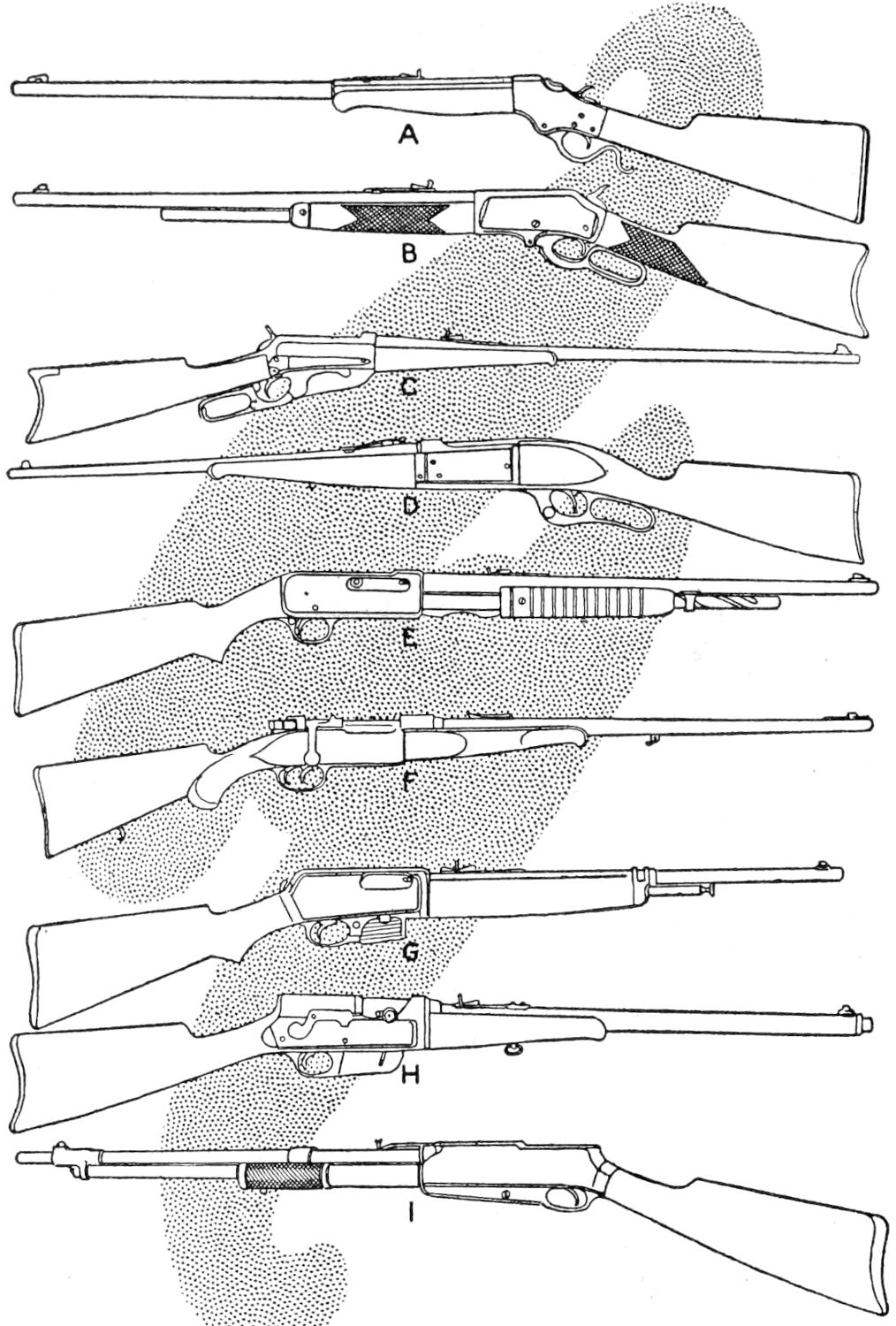
Fig. 1
Various Types of Rifles in Common Use: A, English Model, Single-Shot, with Open Sights and Shotgun Butt; B, Lever-Action Repeater, Tubular Half Magazine; C, Lever-Action Repeater, Box Magazine; D, Hammerless, Lever-Action Repeater; E, Pump-Action, High-Power Repeater; F, Military Bolt-Action, Sporting Model; G, Automatic, Blow-Back Action; H, Automatic, Box Magazine; I, Automatic, Combination Pump-Action
Rifle sights are of several types, of which there are in turn many variations. Only the essentials of the standard types will be considered. The regulation open sights, with which most rifles are fitted at the factory, are the buckhorn rear and the Rocky Mountain front sight. For a hunting rifle the most satisfactory sights are a gold-bead front sight of about ³⁄₃₂-in. diameter, as shown in Fig. 2 at L; a folding-leaf rear sight, shown at O, P, and Q, and a combination rear aperture sight, at M and N, mounted on the tang of the rifle. An arm so sighted is useful for all kinds of shooting. The combination rear sight is used in deliberate shots at a target or at game, and the folding-leaf sight is better than the buckhorn for quick snap shooting.
The sportsman who wishes to master the use of a rifle must have a knowledge of the trajectory of such weapons, and particularly of the rifle he uses regularly. He must know, also, how to aline the sights correctly to get satisfactory results. The trajectory is the path which the rifle bullet takes in passing from the muzzle of the rifle to its mark. The force of gravity acts upon the bullet in flight and the result is that the trajectory is curved, as indicated in the diagram at the bottom of the page illustration. A relatively low trajectory is, of course, desirable in a hunting rifle. The black-powder, or slow-speed, cartridge has a relatively high trajectory, while the high-power smokeless cartridges have relatively low trajectories.
The adjustment of the sights of a rifle is also of much importance. Every rifle is targeted at the factory, but this may be done by a fair shot, using the following method: Arrange three boxes, so that the rifle barrel may rest upon one, and the arms of the marksman upon the other two. Place a bag of sand upon the box, so that the barrel may rest upon it, about 6 in. from the muzzle. Put the target into place, and adjust the sights for 100 yd. If the sights are properly lined up, the shots should fall quite regularly within a 10-in. circle. With peep, or other target, sights, much finer results will be obtained. In moving the sights it must be remembered that to move the rear sight to the right will bring the shot to the right, and vice versa, while if the front sight is moved to the right, the arm will shoot to the left. In making the test, first adjust the front sight so that it is in exact alinement with the center of the barrel, and then all corrections may be made by moving the rear sight.
The proper way to sight a rifle is to hold the front sight just clear of the notch in the rear sight, with the front bead barely touching the outer ring of the bull’s-eye, at the extreme bottom. This is shown at R, Fig. 3. It is the rule of good rifle shot to “see daylight between the sight and the bull’s-eye.” In any event, do not cover up the front sight by drawing it down into the notch of the rear sight, so that only the top of the bead is visible. Another frequent error is to hold the front sight to cover the bull’s-eye.
[49]
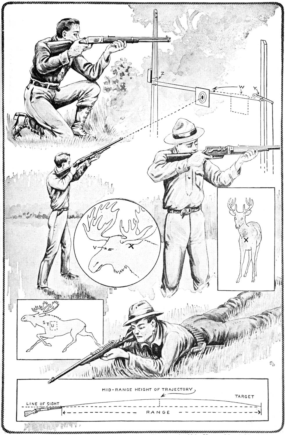
The Off-Hand, Knee-Support, and Prone Positions in Shooting should be Mastered by the Sportsman. The Diagrams Represent Several Vital Shots, the Moving Target, and the Trajectory of a Rifle Bullet
[50]
The sportsman who wishes to become a practical rifle shot should learn how to handle the rifle in the several useful positions, so that he may be able to sight accurately under different conditions. Several of the most widely used positions are shown in the page illustration. The off-hand position, with arm extended, is the most commonly used and best position for the sportsman to practice, for use in the woods. The off-hand, with body rest, or elbow resting on the hip, is good for target shooting. The “Schuetzen” style of holding the rifle, with palm rest, is used only in fine match shooting.
The knee-rest position is often useful for the sportsman in stalking game, when it is desirable to expose oneself as little as possible. A steadier aim may be secured, especially if a strong wind is blowing. The prone position is much used by military riflemen, but they are not permitted the muzzle rest, whereas the hunter often uses it. It is easy to learn, and more accurate shooting may be done in this position than in the off-hand or knee-rest positions.
For indoor practice at a target, the .22-caliber rifle is best. By fitting up a suitable backstop, shooting may be done safely in the cellar or attic. A satisfactory backstop may be made by fastening a plate of iron into a packing box, 3 ft. square, as shown in Fig. 3. The plate must be set at an angle so that the bullets will be deflected to the bottom of the box.
In order that the rifleman may check up his work, it is desirable that a standard target be used. The American standard target, shown in Fig. 3, has been adopted by practically all rifle clubs, and, as the majority of records are made upon it, the sportsman should become familiar with it. The paper targets are inexpensive, and it is easy to draw accurate homemade targets from the original. By the use of disks of black and white paper—known as gummed target pasters—one target may be used several times.
If convenient to do so, the novice should shoot a string of shots every day, in the various positions. Do not try to hurry, but shoot deliberately at first, aiming to secure a good average, rather than a few bull’s-eye shots and many wild ones. With reasonable practice, it is not difficult to score eight bull’s-eyes out of ten shots, when using the prone position. Having attained this proficiency, the sportsman may be regarded as a fair shot, and is ready to take up outdoor target practice with the high-power rifle.
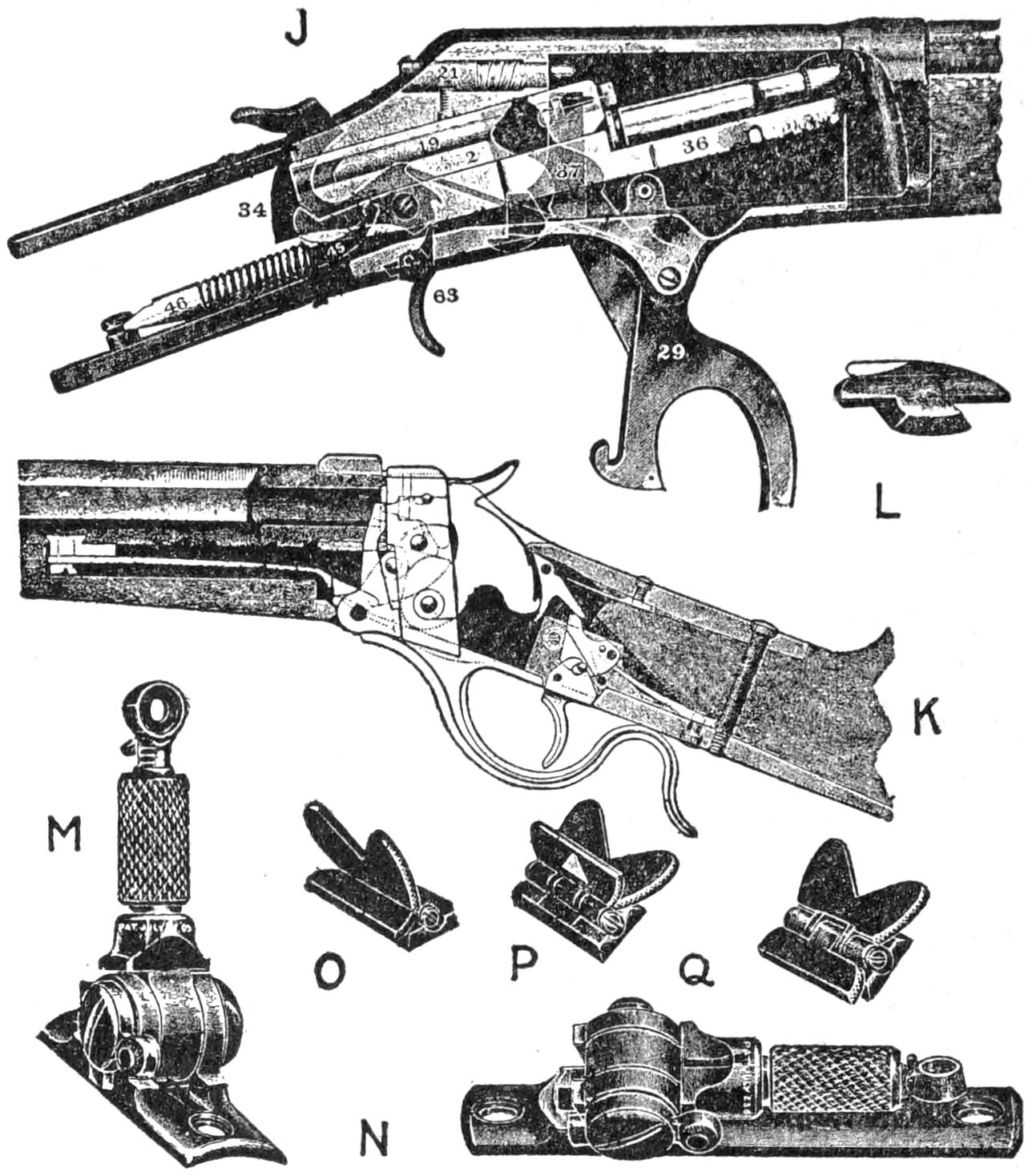
Fig. 2
J, Mechanism of Lever-Action Repeating Rifle; 2, Breechblock; 7, Cocking Lever; 19, Firing Pin, Front; 21, Firing Pin, Rear; 29, Guard Finger Lever; 34, Hammer; 36, Lifter; 37, Locking Slide; 45, Mainspring Plunger; 46, Mainspring Plunger Seat; 63, Trigger
K, Mechanism of Falling-Breechblock, Single-Shot Rifle; L, Gold-Bead Front Sight; M and N, Combination Rear Aperture or Tang Sight, Raised and Folded; O, P, Q, Folding-Leaf Rear Sight, Used as V-Crotched Sight, Straight-Bar Sight, and Folded Flat to Barrel
For outdoor target shooting the .22-caliber, long-rifle cartridge will give very accurate results up to 100 yd. The standard target has a bull’s-eye measuring 6 in. in diameter for 150 yd. Shooting may be tried for a while at a fixed range, then the target may be moved to an unknown distance and angle, and the marksman can try his hand at estimating distance. Instead of changing his sights at varying distances, the sportsman should learn how to estimate the distance of the mark and the approximate elevation of the sights to land the bullet within the circle. This is valuable practice for good shooting in the woods.
After considerable practice at the stationary target, quick firing may be varied by rigging up a sliding trolley arrangement, like that shown in the page illustration. It is easily made by setting up two poles, properly braced, one about 30 ft. tall, and the other about 10 ft., spaced 30 ft. apart. Between the poles, about 8 ft. from the ground, stretch a length of stiff telephone wire, and make a wooden target block W, with a metal sheave wheel, so that it may slide freely along the wire. On the tallest post, a little above the wire, fasten a metal pulley, Z, and at the top of the pole place a sash pulley. Then attach a stout cord to[51] the target block, reeve it through the two pulleys, and attach a sandbag, or other weight, to the end of the cord, On the shorter post, a latch, or trigger, Y, is fastened to hold the target, which is released by pulling a string. With this easily constructed device, much valuable practice may be had, for if the pole is fairly high, the weight will cause the target to slide as rapidly as the average game bird travels. In using this moving target, just as good practice is obtained with a .22-caliber repeater as with a high-power gun. In fact, the high-velocity ammunition should be used only on a regular range, or where a suitable backstop is erected to stop the high-power bullets. Such a backstop may be constructed of heavy lumber, like old railroad ties, in the form of a crib, which is filled in with sand or earth. When a natural background, such as a mound or hill, is at hand, this may be used with safety, but a rocky hillside is not satisfactory, for it is likely to deflect the bullets, and may cause injury through stray shots.
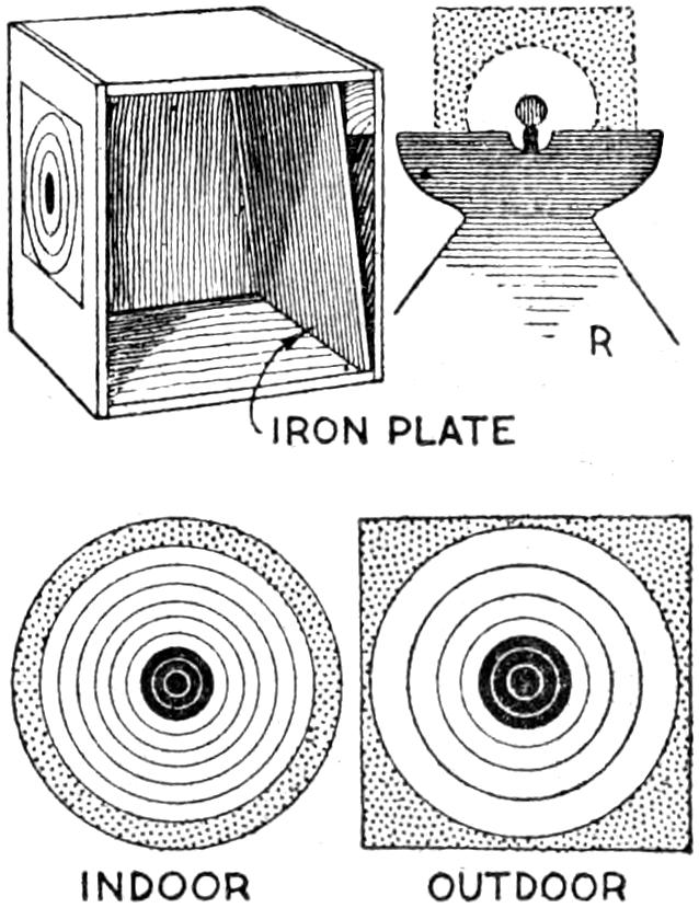
Fig. 3
As our antlered game, like the moose, the Virginia deer, the caribou, and the elk, are held in higher esteem than other American big-game animals, a few practical hints on where to sight, may serve to bring better luck to the sportsman who has yet to bring in his first head. The shoulder shot, shown in the rectangular sketch at S, T and U, is taken by the experienced hunter whenever possible, in preference to any other. It is the object of this shot to break the shoulder joint, and thus prevent use of the forelegs. It is a vital shot, also, because there is a good chance of the bullet passing through either the heart or lungs, which will drop the game in its tracks. This is the most effective of all shots, and as the hunter more often draws a bead while the game is running away, the shoulder shot is used more than any other. The exact spot, at which the aim should be taken, depends upon the distance of the animal, and its rate of movement. If on the run and the range of 100 yd. or more, the sight should be taken at the point S. If less than this distance, sight at T, and, if the animal is standing still, take deliberate aim at U, within the dotted inclosure. This area represents what big-game hunters call the vital zone, and a soft-nose bullet, placed anywhere within this spot, will be certain to stop the game, often dropping it on the spot. It is possible to land a bullet in a vital spot at distances up to 500 yd. with a high-power rifle, but it is very likely that the game will be wounded only, and may escape to die a lingering death. In taking long shots at big game on the run, the sight should be taken well forward and a trifle higher than the marks given, since the hunter[52] must allow for the trajectory of his arm and the time the bullet takes to reach its mark.
The front shot, shown at the right, has as its object to hit the heart or lungs. It is a useful shot, and the sight is taken at the cross indication on the breast. The head shot, shown in the circle, is a brain shot, and is used only by the experienced hunter, when it is difficult to land a shoulder or front shot. As the brain is well up to the top of the head, the best point of aim is shown at V, midway between the eyes and a trifle higher than their centers. This shot is most effective when the hunter stands a trifle above the game, or shoots when the game is charging head down. If on a level, aim just above the eye, and if close to the game, land the bullet just below the eye. The ear shot, as indicated by the cross, is taken at close quarters, and the point to sight for is the inside of the ear at its base.
A good rifle will give a lifetime of service, and the sportsman should take care of it. The best time to clean a firearm of any kind is as soon after shooting as possible, for the powder residue is then fresh and moist, and is more easily and quickly removed. Black powder can be removed with a wet rag, but smokeless powder not only leaves a little powder residue, but also a film of gummy residue on the steel which is not apparent to the eye. Common washing soda, dissolved in water to make a saturated solution, is used to remove it. Any of the ready-prepared nitro solvents are good for cleaning the rifle. A good way to clean a rifle is to use strips of cotton flannel, cut into squares of such size that they will fit snugly, but may be easily pushed through the barrel on the head of the metal cleaning rod. Always clean a rifle from the breech, if possible, by resting the muzzle on a few folded papers on the floor. Push a couple of dry wipers down to the floor to remove the carbon residue. Then saturate another square of cloth with the nitro solvent, and carefully swab out the barrel, turning the rod so that it will follow the spiral rifling. Repeat the operation two or three times; then take a clean wiper, moistened with the solvent, and repeat until the barrel is well lubricated with the cleaning fluid. The barrel should be well oiled with any good, thick oil, or liquid vaseline. The lock mechanism of the arm should be kept clean and very lightly lubricated with any good thin oil, and the gunstock polished with linseed oil.
When watching a kite flying at a considerable height one frequently wonders how the landscape appears from such a viewpoint as would be possible from a kite. Few of us can have the experience of a ride in an aeroplane, but it is quite possible to obtain a view from the kite, by proxy as it were, through the use of a kite camera. A kite of large dimensions would be necessary to carry an ordinary camera taking pictures of fair size, hence it is necessary to devise one of lighter construction, so that a kite of moderate size may carry it to a height of several hundred feet. Such a camera is shown in the illustration attached to a box kite. Details of construction are shown in the smaller sketches.
A camera consists, briefly, of a light-proof box, with a lens at one end and a sensitive plate or film at the other. For a kite camera, a single achromatic lens will suit the purpose. Such a lens is not expensive and may be taken from a small camera. It must be obtained before the camera is begun, since the size of the latter is dependent upon the focal length of the lens and the size of the picture to be made. A camera taking pictures 2 in. square is satisfactory for kite photography, and if it is desired to enlarge the pictures, this may be done in the usual manner.
[53]
The box of the camera is made cone-shaped in order to reduce the weight and air resistance. Its sides are of light-weight, stiff cardboard, reinforced at the corners to insure that no light will enter. The back of the camera is a tight-fitting cover of cardboard, having the same measurements as the picture to be taken. The lens is fitted to an intermediate partition, as shown in the sketch. It is necessary to determine the focal length of the lens and to set it at a distance from the inner side of the cardboard back of the camera—the film surface—so that it will focus properly for photographing distant objects.
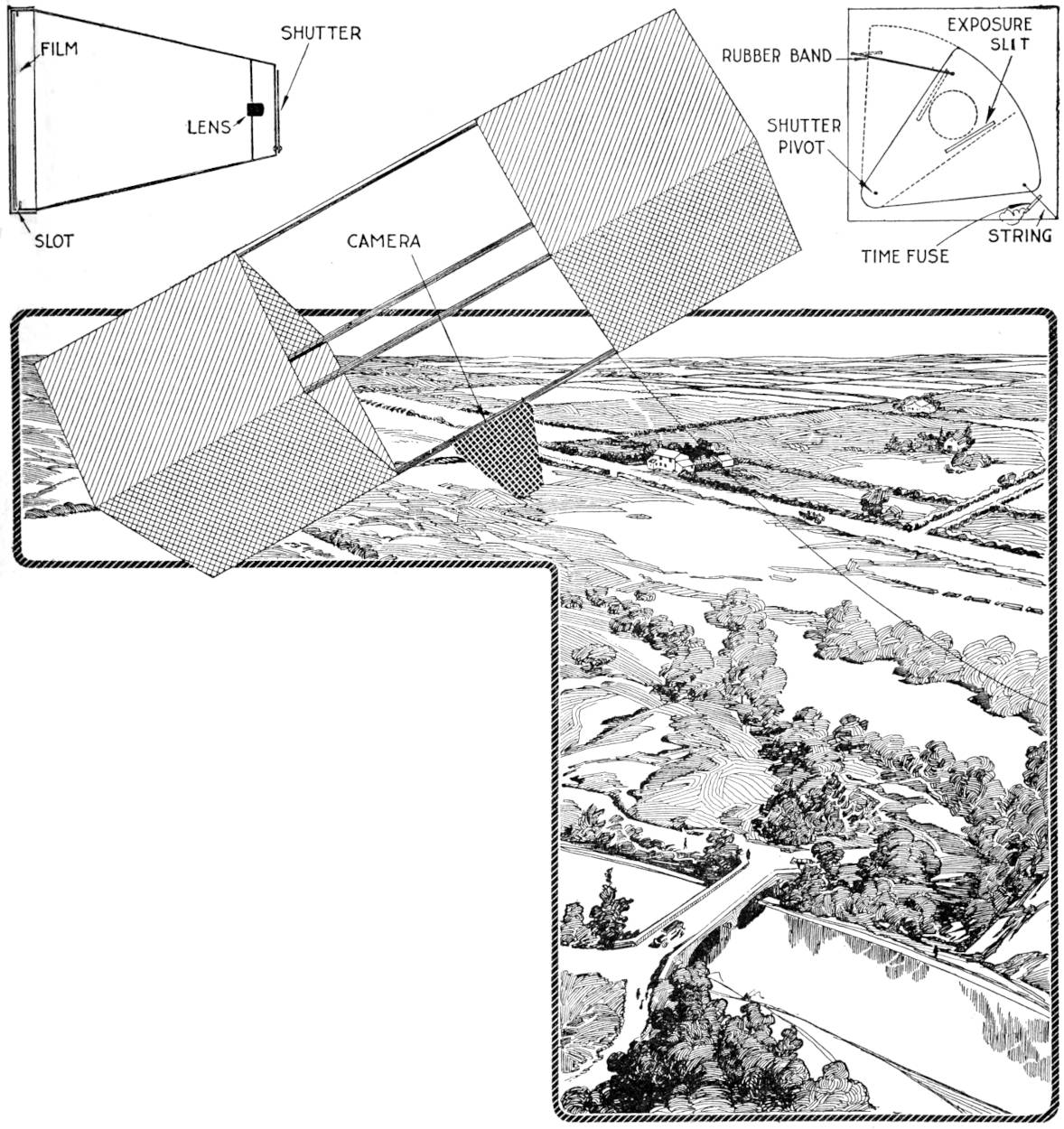
The Kite Camera Offers a Diversion in Photography, and Has Practical and Commercial Uses as Well. The Camera Shown Is of Light Weight, Simple Construction, and Produces Film Exposures Two Inches Square. A Sectional View of Its Construction is Given at the Left, and the Details of the Shutter Device at the Right
The front is provided with a circular opening of a size large enough not to obstruct the view of the lens. A shutter made of thin pressboard is fitted over the opening, as shown in the sketch at the right. A slit is cut in the shutter through which light is admitted in making the exposure as the shutter is drawn back. The size and width of the slit regulates the exposure, and a few trials must be made to determine the most suitable speed of exposure for the lens used. The shutter is pivoted at its lower end and drawn back by a rubber band. A string, to which a time fuse is attached, controls the releasing of the shutter to make the exposure. The string holds the shutter closed against the pull of the rubber band until the fuse burns up to the string, severing it. The fuse must be long enough to enable the kite to attain a suitable height before the string is burned. When the shutter has been set, and the fuse attached ready for lighting, the camera may be taken into the dark room for loading. A piece of film, cut to the proper size, is placed carefully[54] into the light-proof sliding cover, as with a film pack, the sensitive side, of course, being placed nearest the lens.
The camera is attached to the kite securely at the middle, as shown, so that when the kite is in flight a view nearly straight down will be obtained. When all is in readiness the fuse is lighted and the kite started on its flight. By timing experimental flights, the required length of fuse may be determined in order to permit the kite to attain the desired height at the time of exposure.
The kite used for taking pictures from the air should be large enough to carry the kite easily. One of the box type illustrated is satisfactory, although other types may be used. A kite camera for the amateur has great possibilities for experimentation, but requires care in construction and a reasonable knowledge of photography. To the person willing to master the details, kite photography offers a pleasurable diversion as well as practical uses in photographing plots of ground, groups of buildings, manufacturing plants, and other subjects which cannot be photographed by other methods.
Two sheet-metal plates that are well nickelplated may be joined and provided with a suitable opening, to form a useful canteen for the camper or hiker. The illustration shows such a convenience fitted with a shoulder strap ready for use.
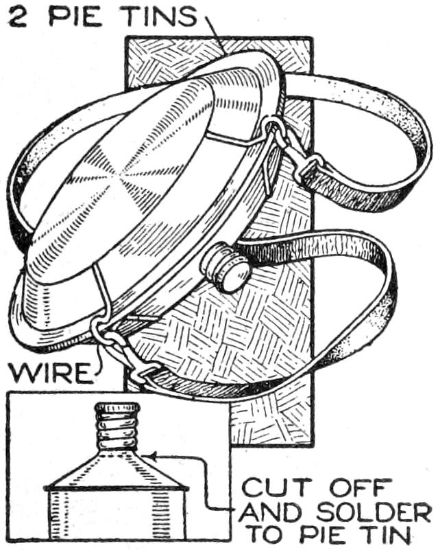
It was made as follows: Two good-quality pie plates were soldered at their edges to form a water-tight container. An opening was cut into the edge and a screw cap, taken from a metal-polish can, was fitted carefully and soldered over the opening. A wire was soldered at each side of the screw cap, providing loops for the snap buckles of the shoulder straps.—J. R. Townsend, Itasca, Texas.
In mixing paint, or paste, it is desirable that all lumps be broken up quickly, and that the forming of lumps be prevented as much as possible. A mixing stick that will aid in this process is made as follows: Procure a stick of wood, that will take nails without cracking, and cut it about 1 in. square and 12 in. long. On one side, beginning ¹⁄₂ in. from the end, drive five 8-penny finishing nails, 1 in. apart. On the next side, repeat the process, beginning the nails 1 in. from the end. Place similar nails on the other two sides, spacing them to offset those on the other sides. The nails cause a thorough mixing of the paste, or paint, prevent the forming of lumps of any considerable size, and by careful stirring will break up all lumps in the mixture.—Edwin R. Mason, Danville, Ill.
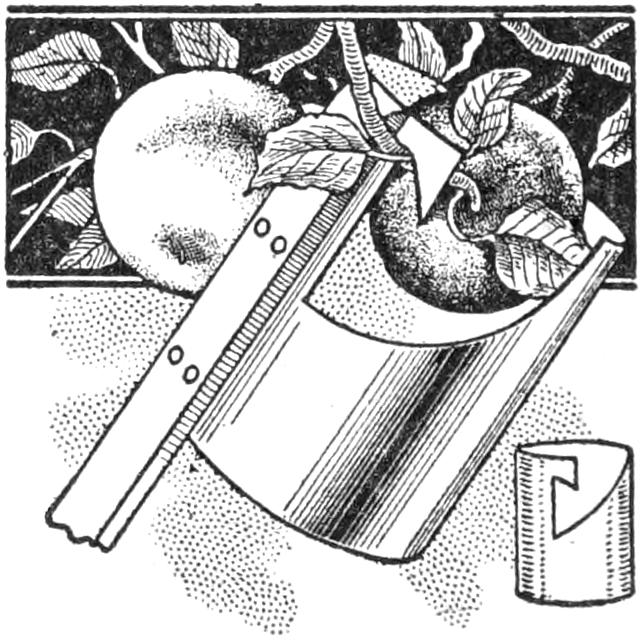
The best apple is usually a little beyond reach, as every boy knows, so I fitted a tin can, cut as shown in the sketch, to a pole and can easily pick the apple that I want. The device is useful for picking many varieties of fruit, and prevents damaging it by a fall. For picking apples or other fruit from the upper branches of trees, where it is almost impossible to reach by the use of a ladder, the tin-can fruit picker is especially handy. The small sketch shows how the edges of the can should be cut to afford the best grip on the stem, making it possible to cut the twig from above or below.—T. A. Charles, Hamilton, Ont.
[55]
Hunting and fishing have always held the most important places in the field of sport. Primitive man was an expert hunter and a skilled fisherman. He had to be in order to secure food and skins, and while but few men are now dependent upon this method of getting a living, the call of the outdoor world is still heard by millions of men and women. This, then, may be reckoned the inheritance which our primitive ancestors have bequeathed to every man, and every man will find health and recreation through it. It would be interesting to begin this chapter at the start and set down the history of weapons, trace the evolution of the hunting arm all the way from the bow down to the modern hammerless shotgun, but as this is a practical article on how to pick out a good gun and the knack of using it, only modern weapons will be discussed. While the novice need not know the detailed process of constructing a shotgun, he will find it an advantage to know something of the way in which a serviceable weapon is manufactured, for with this knowledge he is better qualified to pick out a suitable arm for his own particular use.
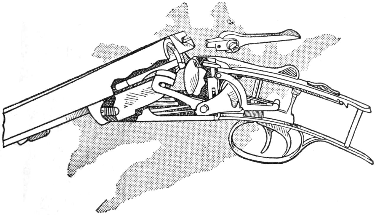
The Side-Plate Lock Is a Development of the Old Hammer Lock with Striker Inside
The frame of a shotgun—that is, the part to one end of which the barrels are affixed, the stock being bolted to the other—contains the lock mechanism, and that the weapon may give the most satisfaction for many years, the stock must be of good quality, of the exquisite temper, and the bolting mechanism—securing the barrels to the frame—must be simple, yet strong and serviceable. For the frame, a solid drop forging is milled to make a shell into which the working mechanism is fitted, and two types of frames are used in making the modern shotguns. The side-plate lock is really a development of the old hammer lock, with the striker inside. This lock is preferred by some shooters because of its neat and graceful lines, and some manufacturers use this type because it enables them to make use of a lighter frame.
The Box Type of Frame Likewise Has Its Champions and Possesses Its Advantages
The Cocking Hook Is an Ingenious Device, with Variations Used on Different Makes of Arms
The box type of frame likewise has its champions and possesses certain advantages. Certainly it makes a strong and rigid frame, and for inexpensive weapons it would be difficult to improve upon. While its square, boxlike form is not graceful in line, it enables the maker to use a spiral, or coil, spring instead of a flat spring for operating the locks, which is an advantage. In brief, the merits of both types may be summed up in this fashion: The use of the box type of lock enables the maker to turn out a better quality of[56] gun at a low price, but in the case of a well-made gun, selling for a reasonable figure, there is very little choice between them so far as dependability and long service are concerned. Both are much used by manufacturers of the finest weapons, hence the shooter may pick out the one which best suits his fancy.
A Hammerless Gun with Roller Bearings to Overcome the Short Leverage and Make It Open and Close Easily
The locks of the hammerless shotgun work inside of the frame or lock, and are cocked by an ingenious little mechanism operated by the movement of the barrels when they are opened. The Anson & Deely cocking mechanism is one of the oldest and best of these devices, and is still used on many American as well as European arms. The levers of this mechanism are hung with pivots in the end of the frame—one end projecting into the fore end and the opposite end resting beneath the hammer toe. As the gun is “broken,” or opened, it presses down the forward end of the cocking lever, and the other end rises and pushes the hammers into the cocked position. This is the principle upon which all cocking devices are constructed, and while it works smoothly and is so simple that it is not likely to get out of order, it is mechanically weak, owing to the short frame required to secure adequate leverage. Perhaps one of the best variations of the Anson & Deely device is one employed by an American manufacturer who makes use of a rod running through the frame from the fore end to the hammer. To each end of this rod is attached a crank, so hung that as one crank is depressed the other rises and pushes the hammer to the cock position as the barrels are swung to open the gun.
A Lug is Forged on the End of Each Barrel, and When Fitted Together They are Brazed
The cocking hook is an ingenious device found on American shotguns and many variations of it are, of course, used on the different makes of arms. The Parker gun is provided with a hook working a slide, thus pulling the hammers to cock. In the Baker, a bent arm is pivoted to the breech to serve the same purpose. Another example of American ingenuity may be noted in the lug-cocking devices used on the Ithaca and Fox guns. This simple arrangement is made by connecting the toe of the hammer directly with the lug, which is an integral part of the barrel. The hammer is thus made to act as its own lever, for as the toe portion rises when the barrel is opened, the striker falls back until it is caught in the notch of the sear.
To guard against the possibility of accidental discharge of the hammerless gun, in which type of gun the hammer must be always at full cock, a safety trigger bolt is utilized. This bolt is affixed in the frame in a vertical position by pivoting it, and to the upper part of the lever is attached a slide placed on top of the tang immediately back of the top lever which opens the barrels. As this safety slide is pushed, the lower end of the lever is brought close up against the triggers, blocking them, and thus prevents them from moving while the safety is in the “on” position. To discharge the gun, the slide must be pushed forward to the[57] “off” position, which moves the lower end away from the triggers. This type of safety is of the nonautomatic variety and can only block the triggers when the slide is operated by the shooter.
The automatic type of safety consists of a block, or bar, fitted in the frame and extending from the safety bolt to the post of the top lever. When the top lever is pushed to one side to open the barrels, this block, or bar, pushes the safety bolt over the triggers, automatically blocking them and preventing accidental discharge. The triggers must be pressed to withdraw the automatic safety bar.

The Rotary Bolt, an American Invention, Is Strongest Device Known for Locking the Barrels to the Frame
To make the shotgun less likely to go off in the hands of the careless gunner, the tumbler safety has been incorporated into the mechanism of a few American weapons. The tumbler safety is a bar, automatically operated by the triggers, and interposed between the strikers and their firing pins. This device makes it impossible for the arm to be discharged by the hammer jarring off when dropped, for the tumbler bar occupies its position between the strikers and firing pins until the triggers are pulled.

The Three-Bolt Mechanism Is One Form of the Rotary-Bolting Principle Used by Many Gun Builders
The practical value of both the automatic safety and the tumbler type of bolt is questioned by practically all experienced gunners. Its presence is designed to make the arm less dangerous in the hands of careless and ignorant sportsmen. This it may serve to do, but since there should be no excuse for tolerating the latter, most handlers of the scatter gun fail to see the utility of the former. The novice should lose no time in acquiring the knack of handling his chosen weapon, and if he will but exercise a little care, he will find the hand-operated safety quite sufficient, for he will not be troubled through accidental discharge of his gun. By far the larger portion of accidents occur through careless handling of the gun and by the untimely pulling of the trigger, either by dragging the gun through the brush or by nervousness, and it is impossible to make use of a safety device to prevent the accidental discharge.

The Fore End Is an Extension of the Stock beyond the Triggers and the Frame
Between 15 and 20 years ago shotgun barrels were made by combining bars of iron and steel and welding them together to form barrels of the proper diameter or bore. When these strips of metal were twisted to make a spiral tube they were welded together to make the familiar “twist,” “laminated,” and “Damascus” barrels. Sometimes three, four, and five strips of iron and steel were twisted together to make the “three-stripe,” “four-stripe,” and “five-stripe” Damascus barrels. This old type of a barrel was strong and flexible, but being comparatively soft, it was easily damaged by denting.

The Comparative Sizes of a 20-Gauge and a 12-Gauge Repeating Shotgun
The modern compressed-steel barrels are fashioned from solid drawn steel, are very hard, will stand much higher pressure than the Damascus type, and since the process of manufacture is simpler, a first-class steel[58] barrel may be produced at one-quarter the cost of the old type. The several manufacturers have adopted trade names to distinguish the various grades of steel barrels. Various trade names come from abroad, and those of American manufacture are labeled “nitro-steel,” “armor steel,” “high-pressure steel,” etc. While differences very likely exist in the quality of the different barrels sold under the several names, all the barrels used by reputable gun builders will be found amply strong to resist any pressure exerted by ordinary charges of powder, hence the cheaper guns are perfectly safe and will stand many years of hard shooting.
In the early models of the breech-loader the barrels were locked to the frame with a bolt operated by a lever placed under the fore end. All modern guns have the top-lever action. In this device a “lump” is fastened to the under side of the barrels near the breech, forming a hinged joint to which the fore end is attached when fitting the barrel and stock together. When closed, the breech end of the barrels is held down to the action and tight up against the breech by a slide, or bolt, which fits into the “lump” attached underneath the barrels. Different makers use various forms of top-lever bolting devices, as the “hook rib” or “extension rib,” otherwise known as the “doll’s head,” and the cross bolt first used by Greener, the celebrated English gun builder. All of these devices are satisfactory on a good grade of gun, but the strongest mechanism is an American invention, known as the Smith rotary bolt. This rotary bolt is tapered and is pushed through an opening in the rib by means of a strong spring. Mechanically this locking device is all that can be desired, and it cannot loosen through manipulation, because of its compensating feature, that is, the spring forces the bolt farther in as the bearings become worn through much service. Many of our well-known builders use this splendid fastening.
Walnut is exclusively used for gunstocks, and the several grades are termed plain American walnut, fine American walnut, English walnut, selected English walnut, fine English walnut, Italian walnut, and Circassian walnut. The plain American walnut is simply a common quality of black walnut, oiled and varnished, and fitted on the cheaper guns. Fine American walnut is of better quality, darker in color, and of better grain. It is strong and durable, and when well oiled and polished by hand, it makes a neat stock for the inexpensive gun. The selected English walnut is of good color and with good grain. When oiled and hand-polished it makes an attractive stock for the knockabout gun. Fine English walnut is usually fitted to guns selling at a higher price, and is generally made to order. Italian walnut is a dark wood with a fine grain and is usually supplied to order on the finest guns. Circassian walnut is the finest wood obtainable, of a rich dark color and a fine curly grain. It is therefore expensive and only finished to order and fitted to the most expensive guns.
The fore end is an extension of the stock beyond the triggers and frame and affords a grip for the extended hand—protecting it from the hot barrel—serves to lock the barrel to the frame, and likewise holds the ejector mechanism. The Deely & Edge, and Snal fore ends are both used on American guns, and they are so well designed and made that it is practically impossible for the modern types to loosen even when the arm has been subjected to long, hard service. Hence this detail of the shotgun need not be considered when selecting an arm.
Although a great many shooters do not use the self-ejector, this handy device will many times prove of great value in the field, for when the birds are coming fast and the shooter happens to score a miss, the self-ejector throws out[59] the empty shell and enables him to shove in a fresh load to bring down the following bird. The nonejecting arm is plenty good and quick enough for trap use, for when shooting “clays,” plenty of time is given each man to reload between shots, but for upland-bird and for duck shooting, the automatic ejector is a desirable addition to the double-barreled gun.
While a good double-barreled gun in the hands of the average shot will very likely bag as many birds as the shooter is entitled to—and it may be depended on to do this when fitted with a good automatic ejector—many shooters prefer the repeating gun. The hand-operated, sliding fore arm, trombone-action, or pump gun is so well-known that no recommendation is needed. It will suffice to mention that it will do everything that a double-barreled gun can perform, and considering that every pump gun is self-ejecting, and its cost less than an equal grade of double gun equipped with an ejecting device, it is not difficult to understand its popularity. So far as accuracy is concerned, the repeater will shoot rather more steadily than the double-barreled gun in the hands of the average man, and after two shots have been fired, there remain four more in the magazine. Rapid firing is not always an advantage, of course, but when after ducks, the third shot is often wanted in the interval that is required to load the double-barreled gun.

The Shells are Started About One-Quarter Inch in the Regular Way Before the Ejector Kicks Them Out
The automatic, or self-loading, shotgun is the logical development of the repeater, and while its mechanism is necessarily more complicated, it has some merits peculiarly its own. The devotee of the double barrel is inclined to believe that the repeater and the automatic shotgun do not balance so well as his favorite weapon, and the man who swears by the pump gun is inclined to think that the automatic arm is balanced like a club and prone to get out of order. Both factions can put up plenty of argument to support their opinions, but to the unprejudiced gunner, both the repeater and the self-loader will prove very fine guns after the shooter has become familiar in handling them. The double-barrel is a mighty fine gun, so is the repeater and again the automatic; so let the gunner pick out the type he likes best.

The Automatic Ejector Mechanism Enables the Gunner to Shove in a Fresh Load for the Following Bird
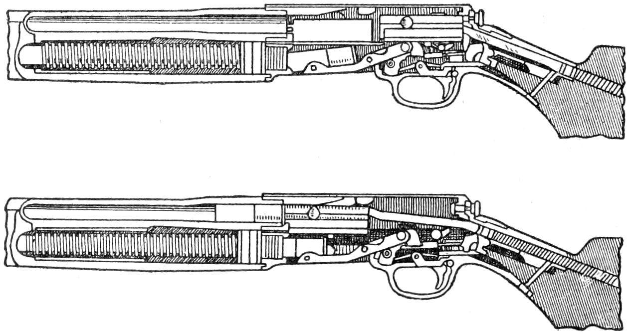
A Self-Loading Shotgun in the Positions of the Action Open and Closed

The Measurements are Taken of the Drop at the Comb and Heel, and of the Stock from the Butt to the Forward Trigger
That the shooter may not be handicapped by using a misfit gun, it is well to make a selection at one of the larger dealers’ where guns of various sizes, weights and lengths, as well as drops in stocks, may be tried until one is found that fits the gunner the best. A good shot can pick up almost any gun and do fairly accurate shooting with it, but he can do better work with a gun fitting him properly. The chief measurements of a gunstock are the length and drop of the stock, and the drop and shape of the comb. The ordinary thickness of the grip will suit the average hand, but in the case of unusually large or small hands, this must be taken into consideration. For the average man these measurements will probably[60] be about right: Length of stock, from forward trigger to center of butt plate, A-A, 14 to 14¹⁄₂ in., drop at comb, B-B, 1¹⁄₂ to 1⁷⁄₈ in., which will give corresponding drop at the heel, C-C, from 2¹⁄₂ to 3 in. A fairly straight stock of good length may be reckoned an advantage for trap shooting, but for use in the field, a somewhat crooked stock with more drop at the comb, say, 1⁵⁄₈ in. with 2⁵⁄₈-in. drop at the heel, will more fully meet the average shooter’s idea of a well-balanced gun. However, as men differ, and there are as many faces and eyes as there are men, every shooter must decide this question for himself. So far as the circumference of the grip is concerned, the size of the shooter’s hand and the length of his fingers will decide this detail. For a small hand, a 7-in. grip is about right, while a grip of 7¹⁄₂ in. will probably fit the large hand well. The question of straight or pistol grip is purely a matter of personal taste, for one is as good as the other so far as accurate handling of the gun is concerned.
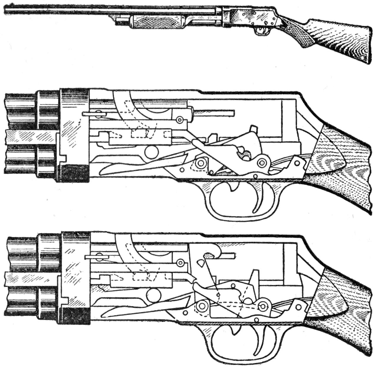
A Repeating Shotgun and the Position of Its Different Parts When Cocked and After Firing
The 10-gauge may be occasionally useful for long-range duck and goose shooting, but for ordinary duck and upland use the 12-gauge is plenty large enough. The larger the gauge the greater will be the killing zone, and up to their ranges the small bores may, for all practical purposes, be regarded as shooting quite as accurately and with as much power as the heavier gauges, that is, the small bores will shoot to kill if held correctly. The standard 12-gauge gun is fitted with 30-in. barrels, weighs 7 to 8 lb., and the standard load for the field is 3 dr. of powder and 1¹⁄₈ oz. of shot. This gives a killing range up to 40 yd. The standard 16-gauge, with 30-in. barrels, weighs from 6¹⁄₂ to 7¹⁄₄ lb., and the standard load is 2¹⁄₂ dr. of powder and 1 oz. of shot, with a killing range up to 35 yd. The standard 20-gauge, with 28-in. barrels, weighs from 5 to 6¹⁄₂ lb. and the standard load is 2¹⁄₄ dr. of powder and ⁷⁄₈ oz. of shot. Best killing range up to 30 yards.
For an all-purpose gun, suitable for wild fowling as well as upland shooting, the 12-gauge is the best choice although the 16-gauge will be found a hard-hitting weapon. For the good shot, the 20-gauge will prove a fine little arm for upland work, only the gunner must shoot well with the small bore to kill his bird clean. Contrary to the notion, the large bore, not the small gauge, will bring the most game to the novice’s bag.
Even though a candlestick is one of the simplest of the smaller household furnishings, it nevertheless can be made a very attractive feature.
For the illustrated mission design, a base, 4 by 4 by ⁷⁄₈ in., should be provided. This is cut, with the grain, for a ¹⁄₂-in.-wide groove, ¹⁄₄ in. deep and extending from one side to within ¹⁄₂ in of the opposite side. In this groove is to fit the handle, which is made from a piece of ¹⁄₂ by 2¹⁄₄ by 3³⁄₄-in. stock. It[61] is provided with a finger-grip hole ³⁄₄ by 1¹⁄₄ in. at one end. Its upper edge should be marked off from the center pedestal and fitted to it. The pedestal can be made from stock 1⁷⁄₈ by 1⁷⁄₈ by 5 in. A tenon, ¹⁄₄ in. long by 1¹⁄₄ in. square, is formed on the lower end. This tenon is to fit a mortise in the center of the base. A slot ¹⁄₂ in. wide is cut centrally in the pedestal, and 2 in. above the lower end, to fit the handle. The upper end of the pedestal is cut straight for ¹⁄₄ in. and squared off to 1¹⁄₈ in. This is to serve as a tenon to fit a corresponding mortise in the ¹⁄₂ by 2-in. square top. The sides of the pedestal are evenly tapered off from the 1⁷⁄₈-in. square base to the lower end of the 1¹⁄₈-in. square tenon, at the top.
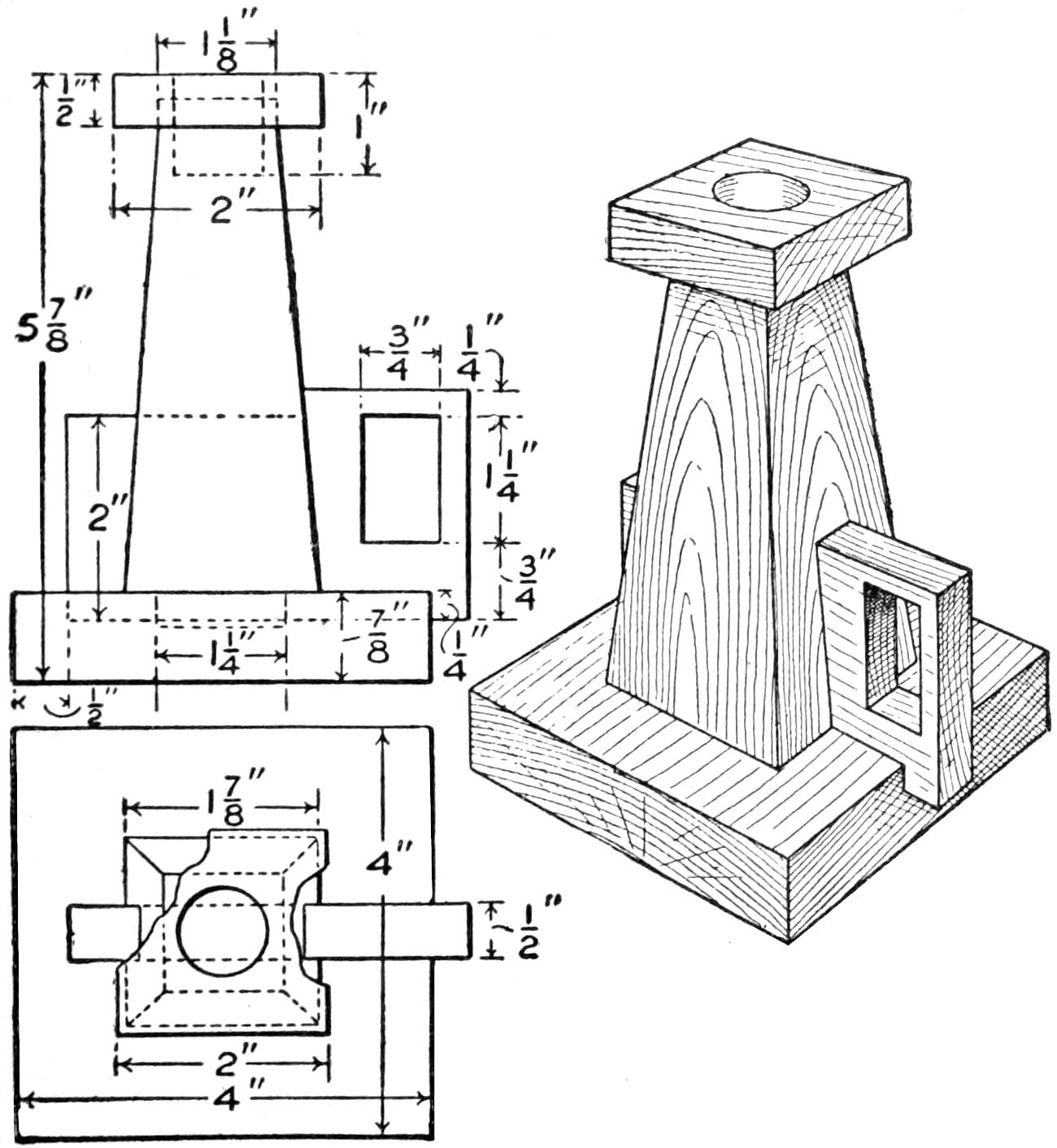
Mission Candlestick of Pleasing Design, That will Appear Well with Other Furniture of This Class
The parts, before assembling, should be thoroughly sandpapered, as considerable difficulty would otherwise be experienced. No nails or screws need be used, as good glue will keep the parts together equally well. When completely assembled, a hole should be drilled through the top and into the pedestal, to fit the size of candle to be used. A carefully applied mission stain and varnish will give a proper finish to the candlestick.—Contributed by G. Crossley, Erie, Pa.
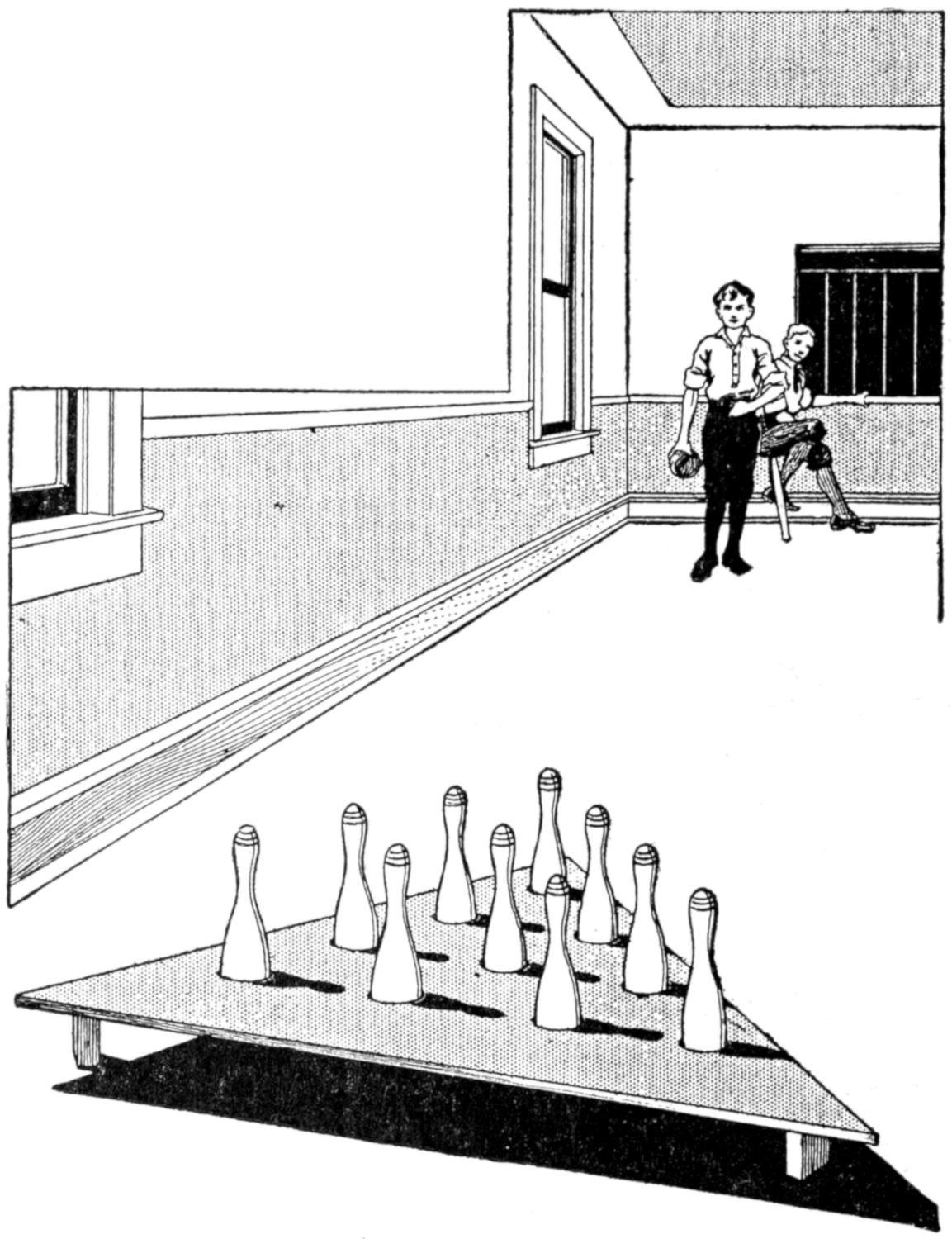
All the Tenpins are Quickly Set, and Each in Its Proper Place
Bowling with a set of small tenpins, which can be purchased at a department store, is a very interesting game. The chief drawback, however, is the setting of the pins. With a little rack like the one shown in the illustration, the interest in the game may be increased considerably. It not only helps in setting the pins rapidly, but insures a good setting with the proper spacing between the pins. It is very simple to make, as it consists of a triangular piece of wood with ten holes bored into it at the proper places, the dimensions of which will be governed by the size of the pins, and three supports. The pins are dropped in the holes and the rack lifted from them.—Contributed by F. K. Howard, Los Angeles, California.
This experiment consists in requesting anyone of a company of spectators to name a card and write it on a piece of paper, whereupon the performer instantly names the card written.
Two persons are necessary, the performer and his assistant. The performer[62] leaves the room while the spectator writes the name of the card on the paper, the assistant supplying the paper and pencil. When the name of the card is written, the paper is folded by the spectator and handed to the assistant with the pen or pencil. The assistant lays the pencil and paper on a table in certain positions to designate the name of the card. Previous to this test, the performer and the assistant must have the positions of the paper and pencil mentally fixed in their minds. Referring to the sketch, the four sides of the table represent the card suits, viz., spades, hearts, clubs, and diamonds; and an imaginary circle divided into twelve parts indicates the number of the card, 1 standing for ace, 2 for deuce, and so on.
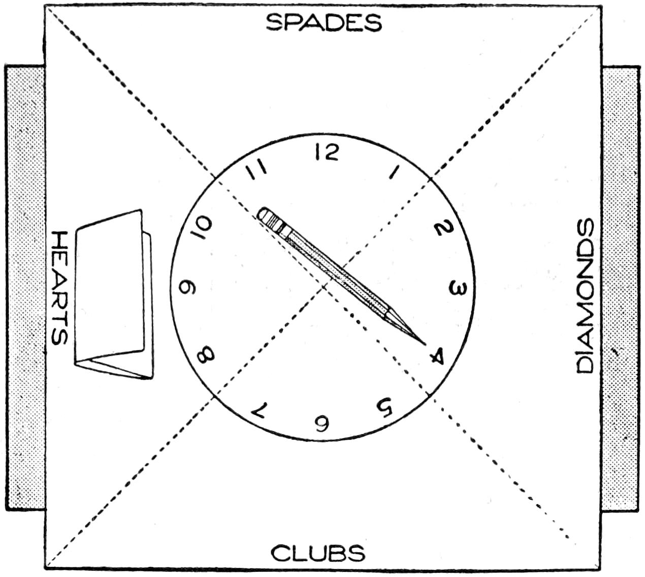
The Markings are Memorized so That Only Positions of Pencil and Paper will be Seen
The assistant, knowing what has been written on the paper, places the paper to indicate the suit, and the pencil is laid so that it points to the number on the imaginary circle, or dial. The one shown in the sketch is designating the four of hearts.
An emulsion of gasoline and water is much used by dry cleaners for removing grease, tar, and paint spots from clothing. It is in the form of a thick, white sirup, which evaporates entirely and is not injurious to any fabric or color. The directions for preparing this emulsion should be followed out carefully.
Dissolve, in 1 qt. of boiling water, ¹⁄₂ oz. of pure castile soap, and ¹⁄₄ oz. of gum arabic. Allow this to cool, and then add 1 oz. glycerin, 1 oz. strong aqua ammonia, 1¹⁄₂ oz. chloroform, and 2 oz. sulphuric ether. Shake well, and pour enough of the mixture into a quart bottle to fill it for ³⁄₄ in. On top of this, pour not more than ¹⁄₄ in. of gasoline, and shake until creamy. Repeat the addition of gasoline, shaking each time, until full. The cleaning mixture will then be ready for use, and may be applied with a rag, or small brush.
If, on adding the first lot of gasoline and shaking, the mixture does not become emulsified, it proves that too much gasoline has been added. In this case, allow it to stand for a few minutes, and pour off the excess gasoline which comes to the top. Shake well, and add a smaller quantity of gasoline. When the bottle is half full, larger quantities of gasoline may be added at a time.
It is interesting to note that the more gasoline is added, the thicker the emulsion becomes, and if the addition of gasoline and shaking is prolonged, a semisolid jelly is formed, which will not run from a bottle.—Contributed by H. E. Zschiegner, Wellsville, N. Y.
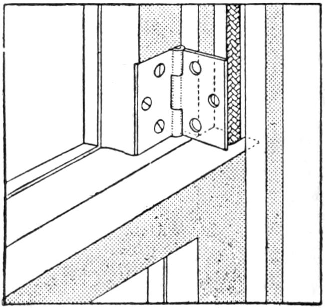
An excellent lock for window sash is to use two small, but strong, hinges one fastened on each side of the top sash close to the upper edge of the lower sash. This allows one wing of each hinge to swing freely which permits it to be swung over the upper edge of the lower sash, locking both securely. In placing the hinges in this position, they are out of sight and not in the way.
[63]
THE SHOTGUN
AND HOW TO USE IT
By Stillman Taylor
PART II—The Choke and Pattern of a Gun
Having picked out a gun that “fits the man,” the matter of choke and pattern should be considered. For trap shooting and for wild fowling, the full-choke gun may be considered a necessity, since it will throw the charge of shot within a relatively small circle; in other words, make a denser pattern. Chokeboring is accomplished by constricting the barrel at the muzzle from ¹⁄₂₅ to ¹⁄₅₀ in., the amount of taper depending on the size of the bore and gauge. The narrowing of the muzzle forces the charge of shot together and prevents the pellets from scattering over a wide area. Guns are bored with varying degrees of choke, from the full to the plain cylinder, and the manufacturers compare them by recording the number of pellets which any given choke will shoot in a 30-in. circle at 30 yd., or any other range selected as the maximum distance. This gives the pattern from which we find that the full choke produces 70 per cent, the half choke 60 per cent, the quarter choke 50 per cent, and the cylinder 30 per cent.
For trap shooting and wild fowling the expert considers it essential that his 12-gauge should be capable of throwing not less than 300 pellets; hence he selects a full-choked gun with a pattern of 300 or better. As a full-choked 16-gauge will pattern about 275, it may be used for ducks with good success. For a general-purpose gun, a pattern from 250 to 275 will prove quite satisfactory for ducks and upland game, and this may be had by picking out a half-choked 12-gauge, or selecting a full-choked 16-gauge. The 20-gauge gives a pattern of about 245 shot, and thus scatters its charge over too large a circle to prove effective on wild fowl, although it is very effective on upland game, which is flushed not over 35 yd. from the shooter. A gun patterning from 225 to 250 may be considered the ideal upland gun, and this may be had by choosing a quarter-choked 12-gauge, a half-choked 16-gauge, or a full-choked 20-gauge gun. These are known as “open-choked” guns, are the most effective at short ranges, up to 35 yd., and cannot be depended upon to kill clean when used at longer ranges.
To handle the weapon well is the desire of every sportsman, and this knack is not difficult to attain, providing the novice will make a good beginning. First of all, it is necessary to hold the gun correctly, and while the forward hand may grip the fore end at any convenient point, a well extended arm gives a better control of the gun when aiming, by giving free play to all the muscles of the arm; hence the gun should be held in a manner natural to the shooter, rather than in imitation of the style of another.
The old manner of aiming the shotgun by closing one eye and sighting[64] along the rib is fast becoming obsolete, for better shooting may be done by keeping both eyes open. Doctor Carter was the first great exponent of binocular shooting, and while but few men can hope to approach this famous gunner’s skill, every one can learn to handle a shotgun more quickly and with greater accuracy by following his common-sense method. It may appear a bit strange at first to disregard the sights and keep both eyes open, and aim the gun by merely pointing it in the desired direction, but to sight along the rib and attempt to see the bead on the muzzle end can only make a slow and poky shot. This old-fashioned method may be good enough for making patterns on a stationary target, but it is not much of a success for wing shooting. For fine rifle shooting the left eye is invariably closed for target work, but for snap-shooting both eyes are kept open, the sights are disregarded, and the aim is taken by pointing the gun at the object to be hit. Of course, there are many good gunners who shoot with one eye closed, but the novice who is anxious to become a good wing shot should make it a point to practice with both eyes open. Vision is always clearer, and the objects more accurately judged with both eyes open than with one, and when this is done, and one eye controls the line of aim, the shooter is not so likely to make mistakes in estimating the distances and the rapidity of the flight of his game. In shooting, the right eye naturally governs the right shoulder, and vice versa, and this is so because habit has trained the eye to do this. To find which is the master eye, hold a pencil out at arm’s length and point it at some small distant object with both eyes open, then close the left eye, and if the pencil still points to the object, the right eye controls the vision, and is the master eye. Should the closing of the left eye alter the aim, the right eye must be trained by practice until it becomes the master eye, or else the gun must be shot from the left shoulder, which is many times more difficult. The modern way of mastering wing shooting is to point the gun where both eyes are looking, and after a little practice this may be done quickly, and the charge thrown more accurately at the object than by closing one eye, or sighting along the barrel in the old manner.
When shooting at clay targets, or at a flying bird, allowance must be made for the swiftness of flight and the distance from the shooter to the game, or in other words, the shooter must calculate the speed of the flying target and allow the probable time it will take for the shot to reach its mark. To make a quick snap shot at the flying target, the gun may be directly thrown at the mark and discharged as quickly as possible, or the gun may cover the mark and be quickly swung ahead and the charge sent at the point where the swiftly moving bird will be found when the shot gets there. Snap-shooting is only possible when the birds are flying straight away or quartering, and as the shooter fires point-blank at the rapidly moving bird, the shot must be delivered so rapidly that only a very quick and responsive trigger and a fast man back of it can hope to score even a fair percentage of hits. A more certain way of aiming a snap shot is to throw up the barrel below the bird, then rapidly swing it to the proper elevation ahead of the moving target, and throw the shot at the point where the line of the aim and the flight of the bird intersect. For shots at quail, woodcock, and partridge in the brush, the quick snap shot often must be taken, regardless of the chances of missing, for to delay even a second will lose the bird. When a bird rises near the shooter, no allowance of lead or elevation are required, and the charge is thrown directly at the bird.
The rapid swing, however, is the most accurate manner of using the shotgun, at all angles and at any distance within the killing zone of the weapon. To make this shot, the gun must be thrown up behind the bird and[65] then rapidly swung ahead of it, throwing the charge without checking the swing of the arm. In this style of snap-shooting, the elevation of the gun must be identical with the flight of the bird, inasmuch as the gun follows it, and if the gun is swung about three times as fast as the bird is traveling, plenty of allowance for the time necessary to press the trigger and deliver the shot at the determined point will be made.
To swing deliberately and cover the bird with the sight, then shove the gun ahead to give the proper lead, is all right for duck shooting where the game is usually seen approaching and thus remains within range for a longer time. But this deliberate style of handling the gun is far too slow for the uplands, and since the rapid swing is the only accurate manner of cutting down the fast bird, and usually useful for wild fowling, the novice should confine his practice to this practical style of wing shooting.
The first great mistake the novice is likely to make is the natural one of supposing that he must take his gun to the field and learn how to handle it by practicing at flying game. This is by no means the best method, and there is scarcely a poorer way of becoming a wing shot, because the gunner is intent upon bagging the game and forgets to observe the many little points of gunnery, shooting high and low, and making the hundred and one mistakes of judgment he would not be guilty of when practicing at a stationary mark. Snap and wing shooting is the last word in shotgun handling, requiring quickness in throwing the gun, as well as a trained eye to calculate the distance from and the speed of the flying target. To acquire confidence in using the gun, begin by shooting at a fixed mark. A good target may be made by obtaining a dozen, or two, sheets of stout wrapping paper and painting a 4-in. circle in the center of each sheet. Tack it up on a board fence or on a board hung on a tree, measure off 60 ft., and try a shot. The shot will not spread very much at this short range, and it will be an easy matter to determine the result of your skill in holding a dead-on to the large mark. To avoid flinching and other movements of the head and body, caused by the recoil, begin your first practicing with a light powder-and-shot charge, say, about 2 dr. of bulk measure, or its equivalent in smokeless, and ⁷⁄₈ oz. of No. 8 or 9 shot. There is no advantage in using a heavier charge, and the recoil of the gun will appear much greater in deliberate shooting at a target than is likely to be felt during the excitement incidental to shooting in the field. A dozen shots at these targets will enable the gunner to make a good score by deliberate holding, and when this can be done without flinching, snap and wing shooting may begin.
The Forward Hand may Grip the Fore End at Any Point, but a Well-Extended Arm Gives a Better Control of the Gun
The object which the gunner should now strive for is to train the eye, hand, and gun to work in unison, and to do this, bring the gun quickly to the shoulder, point it to the mark, and press the trigger without stopping the upward and even swing of the barrels. At the first few trials some difficulty may be encountered with the pressing[66] of the trigger at the proper moment, but a little practice will soon tell how to time the shots. Note the phrase, “press the trigger,” for the trigger is not pulled by the forefinger alone, but rather pressed by closing both hands, the forward hand on the fore end pushing and closing, and the hand grasping the stock being drawn back and squeezed at the same instant. This is easily done, but rather hard to picture. After a few trials with an empty gun, the novice will see the point, and also discover the fact that the recoil of the arm is much lessened by this proper grip of the weapon.
Confine the first practice in snap-shooting to throwing the gun to the shoulder, and when proficient in hitting the mark, try a snap shot by swinging the gun from the side, right to left and also left to right. Do not attempt to check the even swing of the gun, but rather let the barrels swing past the mark, concentrating the mind upon pressing the trigger the instant the line of aim covers the mark. Practice swinging slowly, and after being able to hit the mark with the center of the charge pretty regularly, increase the speed of the swing. In doing this, it will be discovered that the speed of pressing the trigger must also be increased to balance the speed of the moving barrel, and very likely it will be found that the natural tendency is to press the trigger a bit late. This is the common mistake which practically every novice makes when in the field, although the error is likely to pass unnoticed when after game.
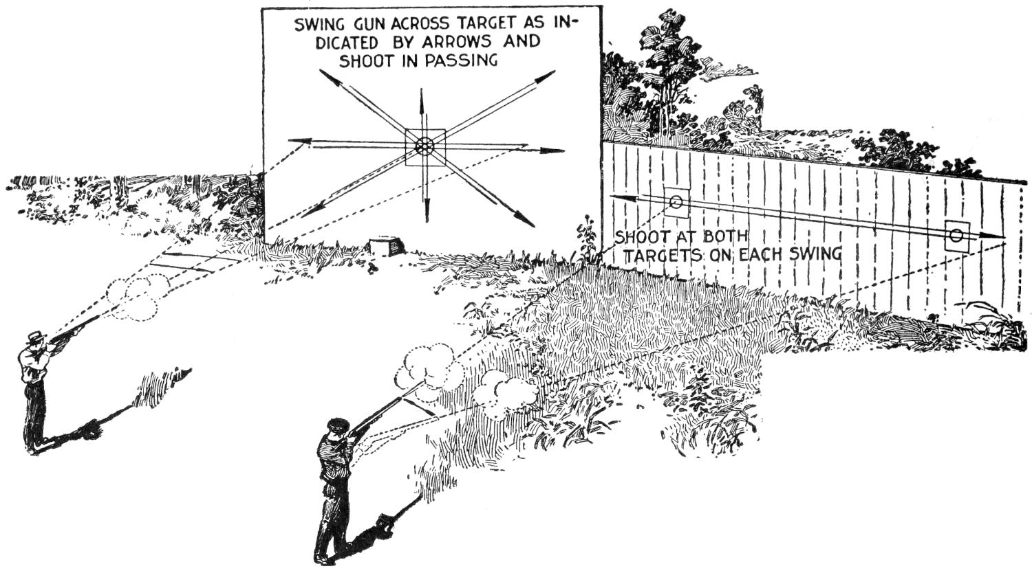
SWING GUN ACROSS TARGET AS
INDICATED BT ARROWS AND
SHOOT IN PASSING
SHOOT AT BOTH
TARGETS ON EACH SWING
Train the Eye, Hand, and Gun to Work in Unison, by Bringing the Gun Quickly to the Shoulder, Pointing It at the Mark, and Pulling the Trigger without Stopping the Motion of the Barrels
As the gunner acquires proficiency in swinging the gun from side to side, try swinging the gun at different angles, changing the angle of the swing with each shot, from right to left and upward, at an oblique angle upward, and so on, until it is possible to hit the mark with a fair certainty from a variety of angles. When trying out the several swings, one should always begin slowly and increase the speed of the swing as he becomes more expert, only making sure to shoot by calculation and not by guess. The manner of acquiring expertness sounds easy and is comparatively easy, and, as it is the backbone of snap-shooting, improvement will be rapid if the novice is willing to practice slowly and master each detail in turn. Do not make the mistake of overdoing the thing at the outset by shooting too long at a time. A box of 25 loads is ample for a day’s practice, since it is not how much one shoots, but how well, that counts.
When the gunner has reached the point where he can hit the stationary target by swinging his gun both fast and slow, he has acquired better control of the weapon than many old shooters, and he is well prepared to take up snap-shooting at flying or moving targets. The access to a gun club[67] where clay birds may be shot at, will prove of much value, but this is not absolutely necessary, since tin cans, bits of brick, and bottles, thrown in the air at unknown angles by a companion, will afford the needed variety. Better than this is one of the inexpensive “hand traps” which project the regulation clay targets by means of a powerful spring worked by a trigger. One of the large powder manufacturers makes a trap of this kind, and a very good trap can be had for $1.50. The standard clay targets cost about $2.50 a barrel of 500. Practice of this sort may be made a very interesting and highly instructive sport, providing the targets are projected from different and unexpected angles, thus simulating the many-angled flight of the live bird.
The use of the second barrel should not be overlooked in practicing with the idea of becoming an all-around wing shot, for the second shot is often needed to kill a cripple, or bring down a bird which has been missed with the first shot. Two-shot practice should begin by placing two paper targets about 20 ft. apart, then shooting at the first one and continuing to swing the gun to cover the second target. Practice swinging from various angles as directed for the initial practice, increasing the speed of the swing as proficiency is gained, and fail not to profit by the mistakes which must inevitably occur to all who try to master the shotgun. After a reasonable amount of practice, conducted along these lines, the gunner may venture afield, and if his acquaintance includes an old seasoned sportsman who will point out the mistakes made, much may be learned regarding the knack of handling the gun, as well as relating to the haunts and habits of our wild game birds.
A good shotgun is a thoroughly reliable and dependable weapon, but as with all tools of the sportsman’s craft, the best results can only be had when the arm is in good condition. It is gun wisdom always to clean the weapon after a day’s shooting, and the amateur should make it a positive rule never to put his gun away until it is cleaned. The sooner firearms are cleaned after the firing the better, and if cleaned before the burnt powder has had time to corrode the steel, much future trouble is saved. In cleaning the barrels, never rest the muzzle against the floor. If a rest is needed, use an old piece of carpet or a bundle of rags. Clean from the breech end only, as any slight dust, or burr, at the muzzle will greatly impair the shooting qualities of any firearm. Never use a wire-wheel scratchbrush, as it will scratch the polished steel; a soft brass-wire cleaner is the only suitable implement for this work. There are several good cleaners to be had. For removing any rust deposits, a brass brush may be used, while for ordinary cleaning, plenty of cloth should be run through the barrels, taking care that it touches every part of the interior. This is easily done by rotating the cleaning rod as it is pushed through the barrel from the breech to the muzzle. When putting the gun away, the barrels should be stopped, at the breech and muzzle, with tightly fitting corks, or gun ropes may be run through the barrels after soaking them in some good oil. To prevent rusting, cover the metal, outside as well as inside the barrels, by smearing on a little heavy lubricating oil. Slip covers of chamois are often used to protect the stock and barrels before putting them in the leather case, but stout woolen covers are better, since chamois is likely to absorb more or less moisture.
The mechanism of a gun is not exactly complicated, but the novice had better leave well enough alone and not attempt to dismount the locks or tinker with the mechanism. The modern steel barrel is very hard and not easily dented, but if so injured, it is better to ship it to the factory for repairs than to trust it to the crude methods of the average gun repairman.
[68]
A gun should be given ordinary good care, and this is not forthcoming if one makes a practice of opening it and letting the barrels drop down with a bang. Snapping the triggers on an empty barrel is likewise foolish. If one desires to practice trigger pressing, put a couple of empty shells in the barrels.
If one owns a good-grade shotgun, the stock is probably finished in oil and hand-rubbed to a nice, durable polish. On cheap arms the varnish is usually employed to give an attractive finish in the store. Of course, this varnish will scratch, and otherwise come off, and spoil the appearance of the arm. If a good finish is wanted, do not re-varnish the stock, but remove all the old varnish by using a little varnish remover, and rub down with oil. For an extra-fine polish, wet the wood to raise the grain; rub down with very fine sandpaper; wet the wood again, and sandpaper a second or a third time; then rub down with oil until the wood is saturated with it, and polish with a cloth, using plenty of pressure, and the stock will be as fine in appearance as if it had the “London oil finish” supplied with all high-grade guns.
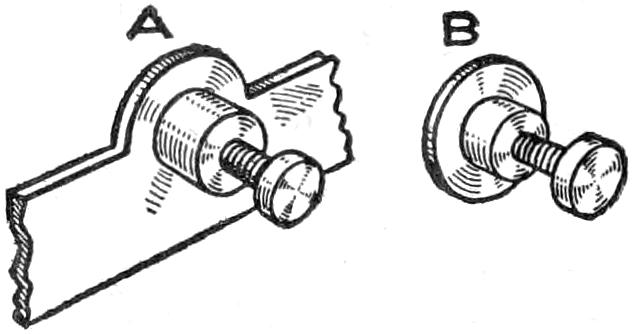
When small brass machine screws and threaded nuts to fit them are needed in small devices, or for experimental work, and the necessary taps and dies are not at hand, secure some old brass globe holders and cut out the threaded hole for the nut. The fastening-screw arrangement on these will answer every purpose very well. Enough metal can be left on each one to fasten it on wood, as shown at A, or they can be cut, as shown at B, if they are to be soldered to metal.
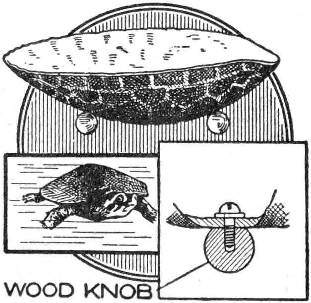
An odd and unusual ash tray can be made from a snapping-turtle shell. Four brass, or wood, balls or knobs, secured with screws, as shown, will keep it balanced. The exact points to place the supports under the tray will have to be determined by experiment, as no two shells are of exactly the same shape.
The fire screen illustrated can be constructed at very small expense. In brief, the screen consists of a light metal frame surrounding three pieces of ¹⁄₈-in. sheet asbestos. The frames inclosing the asbestos pieces are hinged together, as shown in Fig. 1, with special hinges made to meet the requirements.
The asbestos comes in sheets 40 in. square, and this size determines the outside dimensions of the screen. The size of the different sections can, of course, be changed if such a change will better suit the existing needs. By making the screen in sections it may be folded up and thus occupy much less space, and when in use, the sections, by placing them at an angle to each other, serve the purpose of legs, which would be required if the screen were in one straight piece.
The dimensions and form of the outer portions of the frame are given in Fig. 2, and those of the inner portions, or edges, where the hinges are attached, are given in Fig. 3. The joining edges of the frames are made wider than the others for the reason that some of the metal is cut away where the hinges are attached. These frames may be made from heavy tin or galvanized iron, and it will be a simple matter for a tinner to bend them into shape. After all these pieces are[69] bent, fit them together at the corners, making sure that they clamp tightly on the asbestos sheets, as these help to hold the frame in shape. Drill a small hole in each of the corners and provide a small round-head rivet of proper length for each of the holes. The vertical portions of the frame should be placed inside of the horizontal, or end, pieces at the corners.
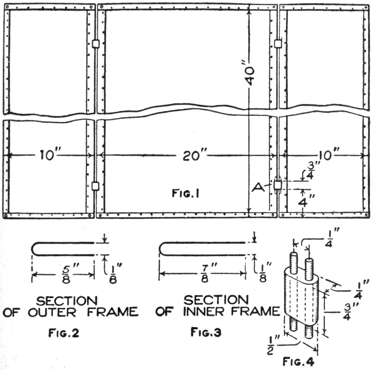
| Fig. 1 | ||
| Fig. 2 | Fig. 3 | Fig. 4 |
Fire Screen Made of Sheet Asbestos Inclosed in Thin Metal Frames Hinged Together
Make four pieces of brass having the form and dimensions given in Fig. 4. Two ¹⁄₈-in. holes are drilled in each of these pieces as indicated. Slots are cut in the inner edges of the frames of such dimensions as will accommodate these brass pieces. The location of these slots is given in Fig. 1. Obtain eight pieces of ¹⁄₈-in. steel rod, about 2 in. long. Place the ends of the brass pieces in the slots in the inner frame and then put the rods through the holes in the ends of them and solder the ends of the rods to the inside of the frames. Make sure that there is no solder run in between the rod and piece of brass, as this will prevent the hinge from operating freely. After the hinges are in place, the frames are riveted together. Notches are cut in the edges of the asbestos sheets at the location of the hinges to allow the latter free movement. The sections of the screen may be made very rigid by placing a number of small rivets around the inner edges of the frame to hold it tightly against the asbestos. The asbestos may be given a coat of bronze, or be otherwise decorated for appearance.
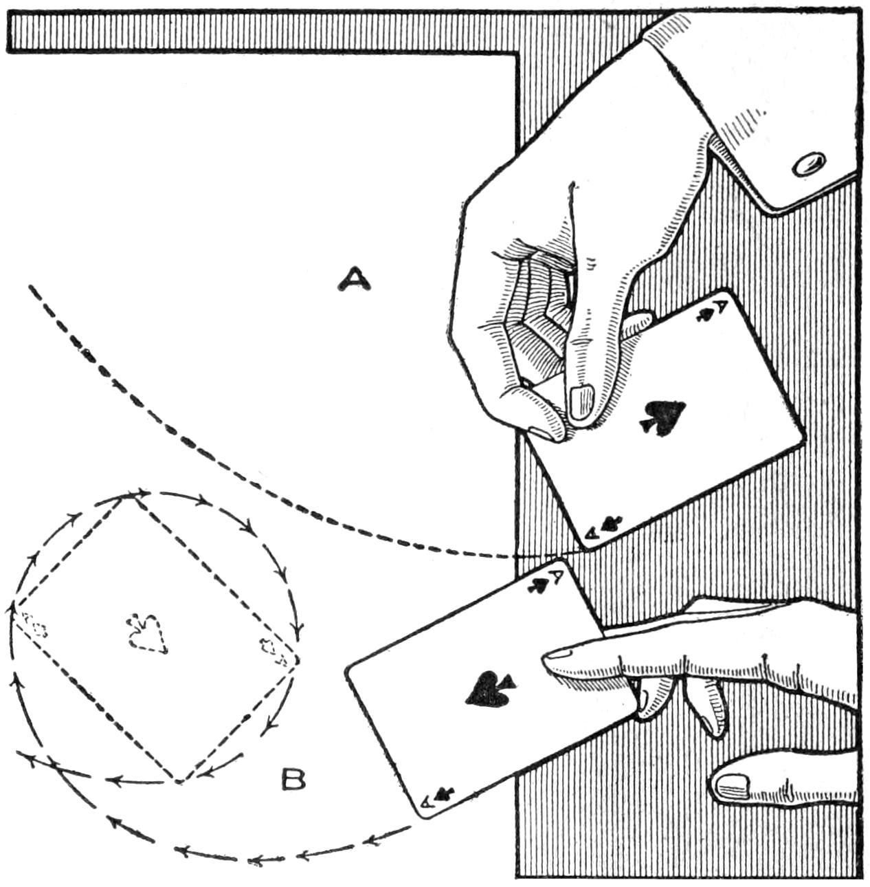
Tossing Cards Accurately so That They will Fall into a Receptacle Set at a Distance
There is an interesting old game that can be played instead of solitaire. It consists in trying to toss the greatest number of cards into a small basket or an upturned stiff hat, set at a distance. If the cards are held as shown at A, and tossed as at B, they may be thrown with surprising accuracy.—Contributed by James M. Kane, Doylestown, Pa.
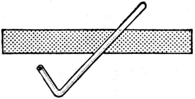
To make this tube, procure a piece of ³⁄₄-in. gauge glass, about 10 in. long, and bend it by heating the glass with a blowtorch 2¹⁄₂ in. from one end, as shown. If this is done in a place where no air will strike the glass while it is heated and the tube is then allowed to cool slowly, it will not crack. It is used by putting the short end under the faucet and drawing on it as on a pipe.
[70]
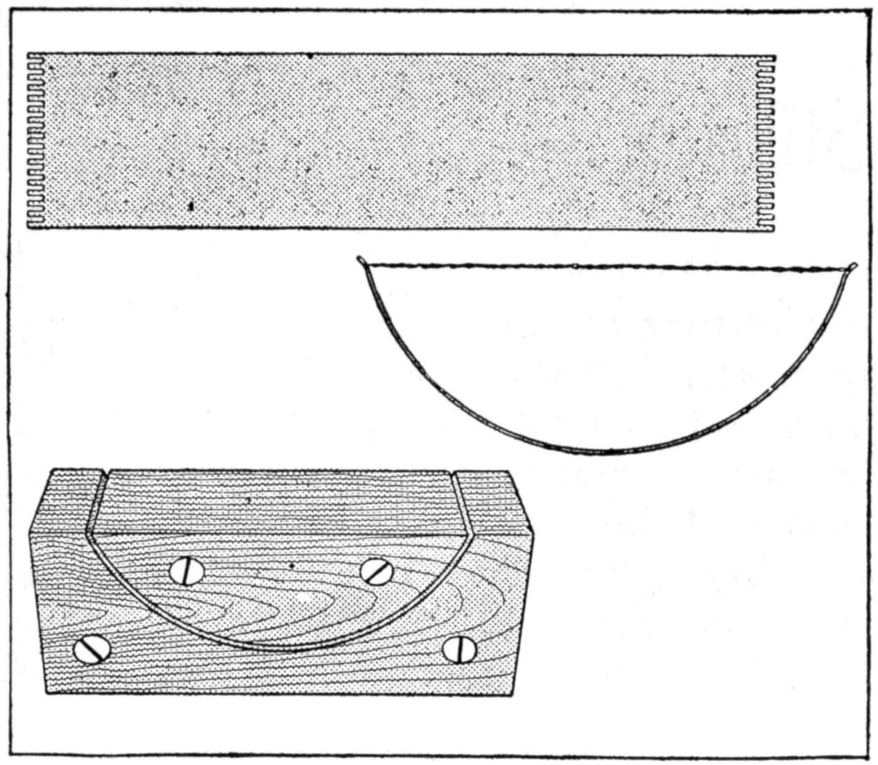
The Twisted Wires Form an Excellent Device for Cleaning a Comb
A very handy device for cleaning combs can be made from a piece of spring sheet brass, 4¹⁄₂ in. long and about 3 in. wide. Notches are cut in the ends of the brass with a hacksaw, making the projections as wide as the saw cut. The brass is then bent into shape with a special clamp made for the purpose, which consists of three pieces of wood, two being cut to form a curved slot, then fastened to the third piece. The brass is sprung into the slot, and then fine wire is stretched between the ends in the notches. The wire should be very fine and two strands twisted together and run through the notches.
The time-honored custom of concealing the house key under the door mat, or in the letter box, when the family has not enough keys to go around, is so well known that an unauthorized person seeking to enter the house would look in these places first of all.
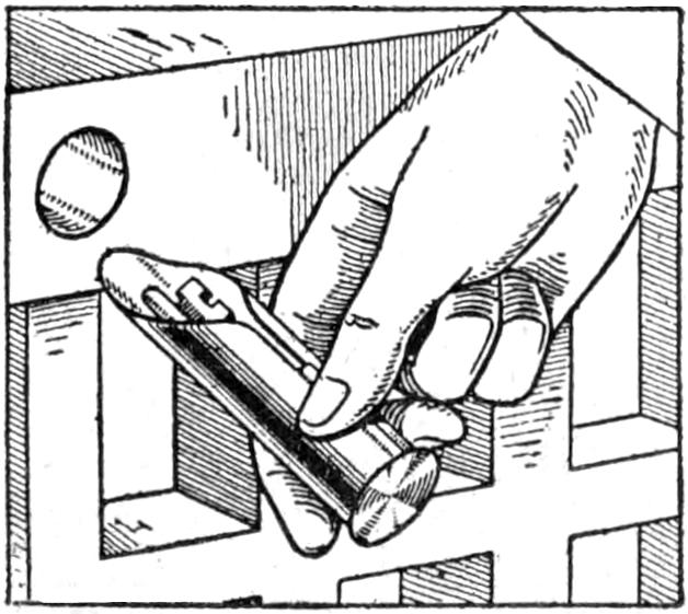
A simple and effective hiding place for the key can be quickly and easily made with the aid of an auger and two pieces of tin. Pick out an obscure section of the porch railing, and in the edge of this bore a ³⁄₄-in. hole, about ¹⁄₄ in. deeper than the length of the key. Make a piece of tin into a cylinder, the same length as the key, so that the latter will slide easily into the hole. At one end of this cylinder solder a 1-in. disk of tin, which will make it appear as in the illustration.
If the key is placed in the cylinder and the latter pushed into the hole until it is flush with the surface, it will scarcely be noticed by anyone not in the secret, and by painting it the same color as the railing it will become still more inconspicuous.—Contributed by Frank L. Matter, Portland, Ore.
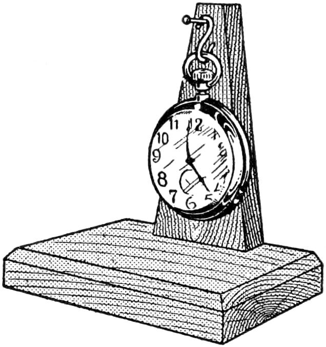
A very interesting experiment may be made with the ordinary dollar watch in illustrating the law of the pendulum. A pendulum 39.1 in. long will make 60 one-way swings per minute, the number of swings varying inversely as the square root of the length. By actual count it was found that the balance wheel of the watch in question made 240 one-way swings per minute, which is just 4 times as fast as the 39-in. pendulum. Therefore, according to the foregoing law, a pendulum ¹⁄₁₆ as long, or about 2¹⁄₂ in., would swing in unison with the wheel of the watch. The question then arises as to what would happen if the watch itself were suspended so as to swing as a pendulum of the latter length. The experiment was made as illustrated, with the result that the watch keeps on swinging continuously. The swing amounts to about ³⁄₈ in., and appears so vigorous that it is almost incomprehensible that the small spring in a watch should be able to maintain so much weight in continuous motion for 24 hours.
[71]
Bait Casting for
Game Fish
by Stillman Taylor
There are many enjoyable phases of the fisher’s art, but bait casting from the free reel probably has a wider appeal than any other branch of angling. The pleasure of handling a short bait-casting rod is in itself a good sport, even when casting done in the back yard is made for distance and accuracy only. Get two or three enthusiastic casters together, and you may have an interesting little tournament, held on a vacant lot, on the lake, or on the greensward of a city park. There is plenty of action in casting from the reel, and it is its variety that has made angling of this type so universally popular. True, considerable practice is required before the caster is able to shoot an accurate plug far off, but the knack may be gained after reasonable application. The handling of the short rod differs from all other angling methods—it is an active sport rather than a contemplative recreation—and when the fun of handling a good outfit is combined with the sport of coaxing out a black bass, shooting a wooden minnow among the lily pads for pickerel, or casting the bait for those pirates of our fresh-water lakes, the wall-eyed pike and the muskellunge, the angler gets a taste of fishing—plus.
A good firearm is necessary to the good marksman and a well-made, nicely balanced rod, to which is clamped a smooth-running reel, is the essential equipment of an able angler. Bait casting is, of course, more a matter of skill than of outfit, but that is no reason why the angler should be handicapped by poor tackle, although large expenditure is not necessary in obtaining a satisfactory outfit. The casting rod may be from 5 to 6 ft. long. Where the caster regards length of cast as the important factor, the 5-ft. length will probably give the best satisfaction. However, the superiority of one over the other in this regard is rather to be found in the elasticity and quality of the rod than its length. The skill of the caster is, moreover, the ruling factor. The 5¹⁄₂-ft. rod is better than the 5-ft. length for fishing purposes, and the 6-ft. rod is more resilient than the 5¹⁄₂-ft. tip. If the greatest range is not of more importance than the landing of the fish, the longer rod will prove the most pleasant to handle.
The split-bamboo rod has many friends, and a well-made rod of this material is a thoroughly satisfactory casting tool. A fine-quality casting rod of split bamboo costs from $10 to $25. A fairly good rod may be bought for $2 or a trifle less, and a smooth-running reel for another $2, while a line for it will bring the total up to about $5. An outfit of this kind purchased with discrimination, while not embodying everything that a critical angler would desire, will cast a long and accurate line and stand up under the strain of handling our heaviest game fish. The one-piece rod is classed by many anglers as the ideal casting rod. The two-piece rod is handier to pack and is more generally used.
The chief fault in bait-casting rods is the stiff action of the tip section. For tournament casting, a fairly stiff rod is desirable. The same requirement[72] holds good for muskellunge and other heavy fishing. A flexible rod affords more pleasure in playing black bass and other active “gamey” fish. However, the best way to test out a rod is by casting with it.

A Serviceable Reel Costing $4, a High-Grade Reel Costing $13.50, and a Fine Tournament Casting Reel Costing $26, are Shown from Left to Right. The Center One Has a Level-Winding Device and a Thumb-Click Drag on the Rims of the Plates. The Tournament Casting Reel Has a Cork Arbor and Jeweled Bearings
The steel casting rod is well liked by some casters, but only a high-quality steel rod is worthy of consideration. It is generally not classed as the equal of a well-made solid-wood or split-bamboo rod, for casting. The better-grade steel rod is springy and flexible, and for this reason is a good rod for casting for black bass. Still, most anglers have a steel rod in their outfits, but it is not as generally used at tournaments as the time-tried wooden rod.
The guide is an important detail of a casting rod. Inexpensive rods are usually provided with large metal guides, while the better rods are fitted with agate guides, or with agate tip and hand guides. A guide, ¹⁄₂ in. in diameter, at the butt of the rod is large enough and will handle the line smoothly.
The single grip is sometimes preferred by casters, but the additional grip placed above the reel is desirable if much fishing is done. Solid-cork hand grasps are most satisfactory, being less slippery when wet and less tiring to the hand than handles made of other materials. If the lower grip is properly shaped with a forward edge, the forefinger will find a firm grip upon it, and the finger hook will not be needed. However, some anglers prefer to use the hook, and if the rod is not so fitted, a detachable hook may be fastened to it. A reel band that locks securely is desirable, and all the better grades of casting rods are so fitted.
The quadruple reel is the logical choice of the bait caster, the spool turning four times to one turn of the handle. As the work demanded of a bait-casting reel is different and more exacting than that of the click reel used in fly casting, its design is radically different. The best type of click reel is of large spool diameter and narrow between plates, while the typical casting reel is its direct opposite—being long-barreled, with plates of comparatively small diameter. For tournament casting the finest outfit will naturally be selected, but for practical work it is unnecessary to pay $25 for a finely wrought reel. Three typical reels are shown in the illustration. The one at the left holds 80 yd. of line, can be easily taken apart for cleaning, and costs $4. In the center is a level-winding reel with thumb click and adjustable drag placed on the rims of the plates. It holds 60 yd. of line, and costs $13.50. At the right is a very high-grade reel for tournament casting. It has a cork arbor, jeweled bearings holds 60 yd. of line, and costs $26.
Any of the better grades of braided silk are suitable for the bait-casting line. The average price for a dependable line is about $1 for 50 yd. A small size line is best, and sizes G and E are preferred. A brown and green, or other dark-colored, line is preferable for fishing. The black and white, all white and other light-colored, lines are satisfactory for tournament use. After a day’s fishing the line should be unreeled and looped around the back of a chair in loose coils to dry, or loosely wound upon a drying reel.
For practice and tournament casting one of the standard ¹⁄₄ and ¹⁄₂-oz. loaded[73] wooden or metal plugs may be used. The popularity of bait casting from the reel has brought forth a large variety of artificial baits. These wooden and enameled lures are used by anglers because they bring the catches.
The wooden minnows, and other forms of artificial bait, may be roughly classed in three divisions: the surface lures for use on top of the water; the diving and under-water baits; and the weedless varieties, which are usually of the surface type. No bait caster’s outfit is complete unless it includes one bait of each class, and to meet fully the different and varying conditions of weather, season, and water, it is a good plan to select one of each type in light and medium-dark colors. A variety of typical baits are shown in the page plate at A, B, C, etc. Many of the baits are provided with one or more eyes for attaching the line, thus enabling the caster to spin his bait at different depths. All of the wooden-body baits will float, and only dive under the surface when reeled in; the quicker they are retrieved the deeper they spin. While many of these baits have been designed especially to entice the black bass, practically all of them are good for pickerel and general fresh-water casting, particularly the minnow baits.
The other items which complete the bait caster’s outfit are the landing net and tackle box. The net should be well made, with a steel hoop 13 in. or larger in diameter, and should have a handle about 3 ft. long. The folding type of net is the most convenient, and is provided with a separate handle. The tackle box may be of sheet metal or leather, with partitions for holding reels, baits, and the angling “what not.” A convenient and serviceable landing net costs $1 or more, and a tackle box will cost about as much.
Although much practice is required before the caster can take his place in a tournament, “getting the hang” of handling the short rod and free-running reel comes quickly. As soon as the simple principles are understood, length and accuracy will come only through practice. Bait casting is easier than fly casting and the angler need concern himself only with the length and accuracy of his cast, since delicacy does not enter into this phase of fishing. The coarser sweet-water fish, like black bass and pickerel, are not frightened when the bait hits the water with a splash—indeed, the splash of the bait attracts them.
Two methods of casts are used by bait casters, the overhead and the underhand or side cast. The overhead cast is used largely by the practical angler, as well as by those who take part in tournament contests, because the bait is projected a longer distance and may be more accurately placed. If the novice will thumb the line, as shown in Fig. 1, with thumb bearing directly on the cross rod of the reel with the ball of the thumb resting lightly on the line, one or two trials will show the correct manner of spooling. The line is retrieved as shown in Fig. 2, care being taken to form correct habits from the start. To make the cast, reel in the bait until it is some 6 in. from the tip, release the click or drag, and press the ball of the thumb firmly upon the spooled line. Carry the rod over the shoulder until it is horizontal or nearly so, as in Fig. 3, and then bring it smartly forward, checking it quickly when it reaches an angle of some 45°, as shown in Fig. 4. This projects the bait forward in a straight line. When the rod is brought forward the tension of the thumb on the spool is released so that the spool will revolve freely, but enough pressure must be communicated by the thumb to prevent the reel from spinning faster than the line is unreeled from the spool, otherwise backlash will occur. The use of the whole arm and the weight of the body, combined with the elasticity of the pliant rod, enables the caster to cover a surprisingly long distance after a little practice. A distance of 150 ft. is not difficult to attain, but for fishing, a well-placed cast of 60 or 75 ft. is long enough to reach promising stretches of water.
[74]
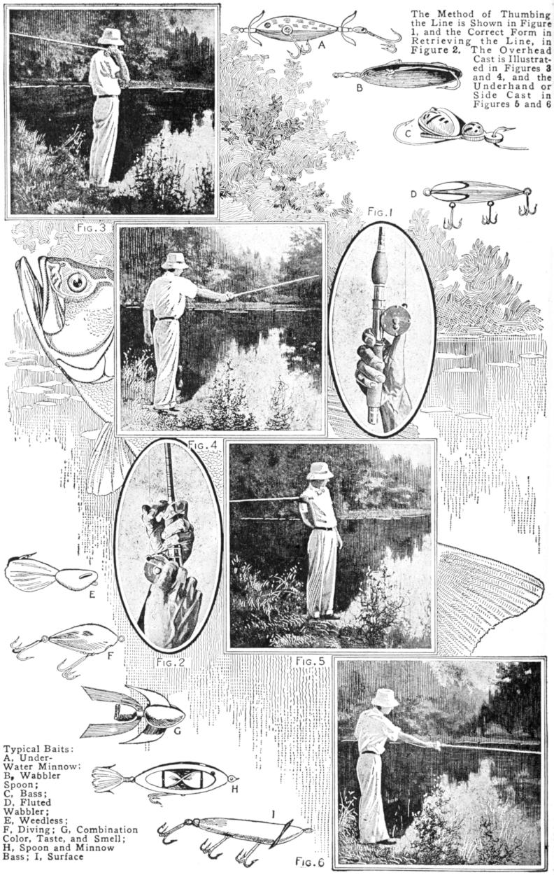
| Fig. 3 | A | The Method of Thumbing the Line is Shown in Figure 1, and the Correct form in Retrieving the Line, in Figure 2. The Overhead Cast is Illustrated in Figures 3 and 4, and the Underhand or Side Cast in Figures 5 and 6 | ||
| B | ||||
| C | ||||
| D | ||||
| Fig. 4 | Fig. 1 | |||
| E | Fig. 2 | Fig. 5 | ||
| F | ||||
| Typical Baits: A, Under-Water Minnow; B, Wabbler Spoon; C, Bass; D, Fluted Wabbler; E, Weedless; F, Diving; G, Combination Color, Taste, and Smell; H, Spoon and Minnow Bass; I, Surface |
G | Fig. 6 | ||
| H | ||||
| I | ||||
[75]
The underhand or side cast is somewhat easier to master, and is made much in the same way as the overhead cast, only the rod is swung horizontally to the rear, the tip on a level with the angler’s chest, as shown in Fig. 5. Bring the rod forward smartly in the direction it is desired to shoot the bait, check the rod when about horizontal, partly releasing the pressure of the thumb, just enough to allow the spool to revolve freely, and check the line as the bait hits the water. Figure 5 shows the beginning of the side cast and Fig. 6 the cast completed. This cast is useful when fishing from a shore overhung with trees, and with practice the bait may be projected a long distance.
The chief factor of skill in bait casting from the reel lies in controlling the line, and the thumb must be trained to do this through practice. Some casters turn the reel sideways with the handle downward while making the cast, but the majority keep the reel level and cast with it in the same position as when reeling in. Thumbing the line is easiest done when the spool is well filled, and if the casting line is not long enough to do this, sufficient common line should be first wound on to fill it.
The successful bait caster is one who possesses an intimate knowledge of the fish he casts for, and while a lengthy exposition is not to form a part of this article, reference to the fish commonly sought by the caster will not be amiss. The fish generally of interest to the bait caster are small and large-mouth black bass, pike, muskellunge, and pickerel. The small-mouth black bass is classed as the finest game fish, ounce for ounce, by many casters. The muskellunge, often confused with the Great Lakes or English pike, is more limited in range than the pike, being found in the Great Lakes region and the waters of the St. Lawrence River.
Since the habits and general characteristics of the large-mouth bass are much the same as its near relative, the small-mouth, the following hints apply to both. When wading, it is well to cast downstream. Cast in the shallows, near the weeds and snags, and close to stumps. As little noise should be made as possible.
For early-spring casting, bass are likely to be found in the shallows and sheltered places during the day, because the water is cool at this season. The pickerel will also be found in the warmer and shallower waters. The most successful baits at this time are the diving minnows, and other under-water lures. As the warmer days of late spring and early summer appear, the bass swim out into deeper and cooler water, while the pickerel remain close to the lily pads. The wooden minnows are excellent baits to use at this season. When the weeds are very thick, one of the several kinds of weedless baits may be used.
The early-morning and late-afternoon hours are the best for midsummer casting, and the shallow places are the good spots to work over. If there are any brooks or streams emptying into the lake or pond, do not neglect to work this stretch well at the mouth. When the sun is low, the white or light-colored surface baits may be substituted for the medium-dark colored diving varieties, and for casting after dark, a luminous or moonlight bait will often give good results. During the fall months fishing conditions are similar to casting in the spring, but the deep water is then the warmest, and the under-water or diving baits are usually the best.
To catch bass, the angler must cast his bait where the fish are feeding, and he will find it an advantage to match natural conditions, so far as possible, in selecting his baits. For casting on bright days in clear waters, the red, white and red, white, or green minnows are good lures, as are also the silverplated spoon baits. Cast well ahead of the boat, and reel in very slowly to keep the plug spinning well below the surface. On cloudy days and in muddy waters, after a heavy rain, for example, use red and yellow baits and goldplated or burnished-copper spoons. The best all-around bait—equally good for bass and pickerel—is one of the green-backed minnows,[76] but no one bait can be expected to meet all conditions, hence the caster should have a fair assortment of baits.
A stiff casting rod with plenty of backbone is essential for muskellunge. The angler is out after big game and must be prepared for the sport. A hard, braided silk line, size E, and 3-0 or 4-0 hooks, snelled and swiveled, are the best. Any of the wooden baits suitable for pickerel—the minnows especially—are good for muskellunge. A man to handle the oars is a handy companion, and after casting the bait just outside the weed bed, make for deep water as soon as a fish is hooked. The fish will be seen and felt quickly enough, and when it breaks water and leaps in the air, give it a little slack line quickly, otherwise the strain will snap the leader. A twisted, bronzed trace is the best to use between line and bait, and this need not be longer than a foot—6 in. is enough. When the fish is brought alongside, shoot him through the head with a revolver which is probably the most satisfactory manner of making an easy landing.
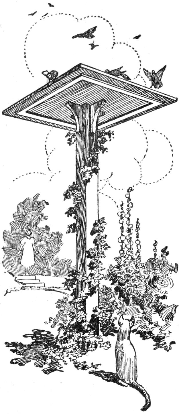
Our bird table is a source of great enjoyment, particularly since the birds feel secure from cats or other enemies because of the construction of this ornament in our garden. The sketch shows the arrangement of the table braced at the top of a 6-ft. post. Shrubbery surrounds the table and a light evergreen climber clings to the post, yet does not give the cats a good foothold.
Experience has taught us that birds in general prefer bread crumbs to other varieties of food, and they are also fond of cracked wheat. The linnets like oranges particularly. We cut an orange in two and place the halves on the table. It is amusing to see the birds balance on one side of the orange while they peck at the fruit. Soon the orange peel is almost entirely emptied. We provide a small basin of fresh water on the table, and the birds use it as a drinking cup as well as a bathtub.—F. H. Sweet, Waynesboro, Va.
Pictures printed on glossy, semi-glossy, or semimat paper may be given a high gloss by the following method: Obtain a sheet of clean glass, without scratches, and apply a solution of a piece of paraffin, the size of a walnut, in one pint of gasoline. Use a soft cloth, and when the glass is dry, rub until all traces are removed. Soak the prints in water for 10 minutes and place them on the glass, face down. Place a clean blotter over them and roll on it with a print roller, to remove excess water and to give them a good contact with the glass. Dry the prints in a warm place, preferably where there is a draft.—M. E. Fuller, Detroit, Michigan.
A shaving brush is injured by permitting it to remain in the mug to dry. It should be suspended with the hair down so that it may dry thoroughly and quickly. A hook made from a piece of wire bent to form a loop, with a pointed section at each side of it, may be made easily. The loop should be of a size to fit the thin portion of the handle, and the pointed ends of the wire are driven into the wall or other support. A loop may be made at each end instead of pointing the wire and the device fixed to the wall with two small screws placed through the end loops.
[77]
How To Build
A Canoe
By Stillman Taylor
PART I
Specifications and List of Materials
Canoe making is commonly considered more difficult than building the larger and heavier craft but many amateurs with only ordinary experience and tools have turned out satisfactory canoes, and if the simple directions given here are carefully followed out, the work will proceed rapidly and no difficulty will be encountered. Working with light materials, the canoe builder must pay particular attention to the workmanship, and, as it is many times more difficult to patch up mistakes in a canoe than it is in rowboats or other heavier craft, the work must not be hurried, but plenty of time taken to do each and every part well and in a workmanlike manner.
The craft described, which is the regulation open or Canadian model, is comparatively light and draws very little water. It is not a flimsy makeshift, but a stiff and thoroughly dependable canoe designed for long service, which, barring accidents and given reasonably good care, will continue to give satisfaction for many years. The tools needed are the common ones found in most homes, consisting of a rip and cross-cut saw, chisel, screwdriver, drawknife, awl, brace and bits, rule, hammer, vise, plane, and three or four cheap wood, or metal, screw clamps. The list of material given is for a canoe having a length of about 16 ft., 31-in. beam, 18-in. depth at the ends, 12¹⁄₂-in. depth amidships, and weighing from 60 to 70 lb., according to the material.
While oak or ash makes the best stems, other woods may be used, rock elm and fir being very satisfactory substitutes. Where cedar is specified, spruce pine, cypress, or fir may likewise be employed. The materials for molds and ribbands, which are required to give form to the craft, may be cut from any cheap stuff, and this will reduce the cost somewhat.
| STEM, 1 piece oak or ash, 6 ft. long and ³⁄₄ in. square. | ||
| KEELSON, (inside keel) 1 piece oak or ash 14 ft. long, 3¹⁄₂ in. wide, ³⁄₈ in. thick. | ||
| GUNWALES, 2 pieces oak or ash, 16 ft. long, ⁷⁄₈ in. wide, ¹⁄₂ in. thick. | ||
| SEAT RISINGS, 2 pieces oak or ash, ¹⁄₂ in. square. | ||
| FENDERWALES, 34 ft. ¹⁄₂-in. half-round molding. Oak or ash best for hard knocks. | ||
| OUTSIDE KEEL (may be omitted if desired), 1 piece oak, 14 ft. by 1 in. by ¹⁄₂ in. thick. | ||
| DECK BEAMS, 2 pieces oak or ash, 8 in. long, 1¹⁄₈ in. wide, ³⁄₄ in. thick. | ||
| SEAT FRAMES, 2 pieces oak or ash, 30 in. long, 3 in. wide, ³⁄₄ in. thick. | ||
| SEAT FRAMES, 2 pieces oak or ash, 12 in. long, 2¹⁄₄ in. wide, ³⁄₄ in. thick. | ||
| PLANKING, cedar or pine, 100 sq. ft., ¹⁄₈ in. thick. Best secured by purchasing 25 ft. of 1-in. lumber, and having same dressed on two sides to ¹⁄₈ in. thick, and in lengths of 12, 14 and 16 ft. This will give the minimum amount of waste. | ||
| BACKBONE, 1 piece cedar or pine, any cheap stuff, 16 ft. long, 4 in. wide, ⁷⁄₈ in. thick. | ||
| MOLDS, 1 piece any cheap stuff, 16 ft. long, 1 ft. wide, ⁷⁄₈ in. thick. | ||
| RIBBANDS, 8 pieces any cheap stuff, 14 ft. long, ³⁄₄ in. wide, ¹⁄₂ in. thick. | ||
| RIBS, 360 running feet, cedar, 1³⁄₄ in. wide, ¹⁄₈ in. thick. | ||
| BREAST HOOKS OR DECKS, 1 piece cedar or oak, 32 in. long, 9 in. wide, ³⁄₄ in. thick. | ||
| 1 | lb. 2-in. wire nails to make form for keel. | |
| 1 | lb. ⁵⁄₈-in. copper clout nails, for fastening ribs. | |
| ¹⁄₂ | lb. ³⁄₄-in. copper clout nails, for fastening seat risings. | |
| 18 | 1¹⁄₄-in. No. 8 brass screws, for fastening decks and deck beams. | |
| 24 | 1-in. No. 6 brass screws, for fastening seats. | |
| 4 | lb. patent marine glue to cement canvas to planking. | |
| 3 | oz. No. 2 ounce copper tacks to fasten canvas with. | |
| 11 | ³⁄₄ | yd. No. 6 ounce canvas for covering hull. |
| 1 | lb. ³⁄₈-in. copper tacks to fasten planking to ribs. | |
[78]
The first step in the construction of a canoe is to get out the backbone and the molds, or forms, which give the correct dimensions and shape of the craft. The backbone may be made from any inexpensive soft wood, such as cedar, spruce, pine, or cypress; and for making it a piece of lumber, 16 ft. long, 4 in. wide, and ⁷⁄₈ in. thick, is used. By referring to Fig. 1 it will be seen that the upper edge measures exactly 15 ft. 8³⁄₄ in., and that the lower edge is ¹⁄₂ in. longer, giving a total length of 15 ft. 9¹⁄₄ in. The spaces numbered from each end of the backbone toward the center, as 1, 2, 3, and 4, indicate where the corresponding molds are to be placed. Seven molds are used and as a canoe is tapered alike at both ends the molds are numbered alike and are made exactly to the same dimensions.

Fig. 1
The First Step in the Construction of a Canoe Is to Get Out the Backbone and the Molds, or Forms, Which
Give the Correct Dimensions and Shapes of the Craft
A good way to lay out the backbone accurately is first to mark the total length, making the lower edge 1 in. longer than represented in Fig. 1, then measure along the top edge exactly 22¹⁄₄ in., and run a pencil line across. From this line measure off ³⁄₄ in. and draw a second line across the width of the board parallel with the first. This space represents the thickness of the mold, and it is marked 1. Measure off 23¹⁄₄ in. and make two parallel lines as before and number it 2, measure another 23¹⁄₄-in. length and number it 3. Begin measuring from the opposite end of the board as in the first instance, 22¹⁄₄ in. and give it number 1, then mark off 2 and 3 the same as for the end already marked. The board is then cut off at the bevel mark at each end.
The molds which give the form to the hull are shown and numbered in the order that they are fastened to the backbone. To get out No. 1 mold draw a rectangle on a sheet of stiff paper exactly 13⁵⁄₈ in. long and 11 in. wide as shown in Fig. 2. Run cross lines to divide it in quarters and mark out the center mortise for the backbone, which is 5 in. deep and ⁷⁄₈ in. wide. Measure 4 in. toward each side from the outside edge of the backbone mortise and mark the mortises for receiving the gunwales, which are 1⁵⁄₈ in. long and ³⁄₄ in. wide or deep. To obtain the correct bilge curve lay the rule on the bottom line and measure off exactly 1 in. to the left of the center dividing line and make dot 0. Measure 2³⁄₄ in. farther to the left, to A; turn the rule at right angles and measure 2¹⁄₈ in. inside the line and make dot 1. Measure 1¹⁄₂ in. to the left of A, turn rule at right angles and measure up the sheet exactly 4⁷⁄₈ in. and make dot 2, which will be ¹⁄₄ in. inside of the left vertical line. On the center horizontal line, which is 1¹⁵⁄₁₆ in. above dot 2, mark dot 3, ¹⁄₁₆ in. from the left vertical line. Measure off 2 in. above the horizontal center line and make dot 4 on the vertical line. The space between these two dots is the widest part of the bilge curve. Lay the rule on the bottom line of the gunwale mortise and measure off ³⁄₁₆ in. from the outside line and make dot 5. Pencil the angle from dot to dot and draw in the full curve. Cut out the half section, fold on the vertical center line, and draw the right side.
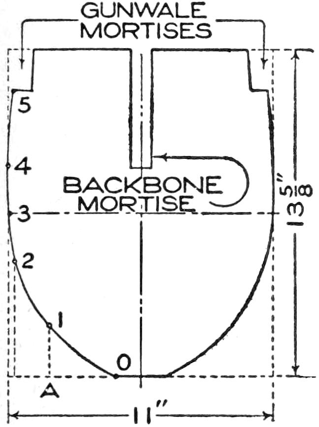
Fig. 2
Two complete No. 2 molds are required, but it is more convenient to make each mold in two sections. Each half is made 11¹⁄₂ in. wide and 12 in. deep, as shown in Fig. 3. First draw a rectangle to these dimensions and[79] run cross lines to divide it into quarters. Beginning at the upper right-hand corner, mark the mortises for gunwales and backbone, which, being only one-half of the complete form, will be ⁷⁄₁₆ in. wide and 3¹⁄₄ in. deep. Laying the rule on the outside line immediately below the mortise, draw a second mortise for the keel, which is ³⁄₈ in. deep and 1¹⁄₂ in. wide in the half section. Measure off 1³⁄₄ in. to the left along the bottom line from keel mortise and make dot 1. The dot 2 is made by measuring 2¹⁄₂ in. to the left of 1, turning the rule at right angles at B and measuring ⁵⁄₁₆ in. inside the line as shown in the sketch. Make the dot 3 at a point 1³⁄₄ in. to the left of 2 and ³⁄₄ in. inside of the line. The dot 4 is 1³⁄₄ in. from C and 1³⁄₄ in. inside of the line. The dot 5 is 1¹⁄₄ in. farther to the left and 3¹⁄₄ in. inside of the line. The dot 6 is ⁵⁄₈ in. from dot 5 and 4³⁄₄ in. inside of the line, which will bring it ³⁄₈ in. inside of the left vertical line. At a point 1¹⁄₂ in. above 6 make dot 7 on the marginal line, and dot 8, 1¹⁄₄ in. above it. Between the dots 7 and 8 is the widest part of the bilge curve. Dot 9 in exactly ¹⁄₄ in. inside of the vertical marginal line. These dots produce the angles, and it is only necessary to trace in the full curve and cut it out to make a pattern for the other three half sections needed.
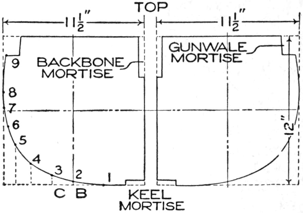
Fig. 3
It Is More Convenient to Make Each Mold in Two
Sections, as Two Complete Molds are Required
The molds No. 3, Fig. 4, are located near the center of the canoe and are made a trifle wider. Make a rectangle 14³⁄₈ in. long by 12 in. wide and draw cross line dividing it into quarters. Trace the half mortises for the backbone, gunwale, and keel from the No. 2 mold pattern. Lay the rule on the bottom line and measure off ¹⁄₂ in. to the left from the center vertical line and mark dot 1, which is the beginning of the bilge curve. At a point 2³⁄₄ in. to the left and ³⁄₄ in. inside of the line place dot 2, and 2 in. to the left of this and 2¹⁄₄ in. inside of the line place dot 3, then 1¹⁄₈ in. farther to the left turn the rule at right angles and measure up 4 in. inside of the line for dot 4, which is ¹³⁄₁₆ in. inside of the left marginal line. At a point 2 in. above dot 4 make dot 5 on the marginal line and 2¹⁄₈ in. above it make dot 6. The space between gives the widest part of the bilge curve, with dot 7 exactly ¹⁄₄ in. inside of the marginal line, measuring along the bottom of the gunwale mortise. Trace the angle and from it run the full curve and use this for a pattern for cutting out the other molds.
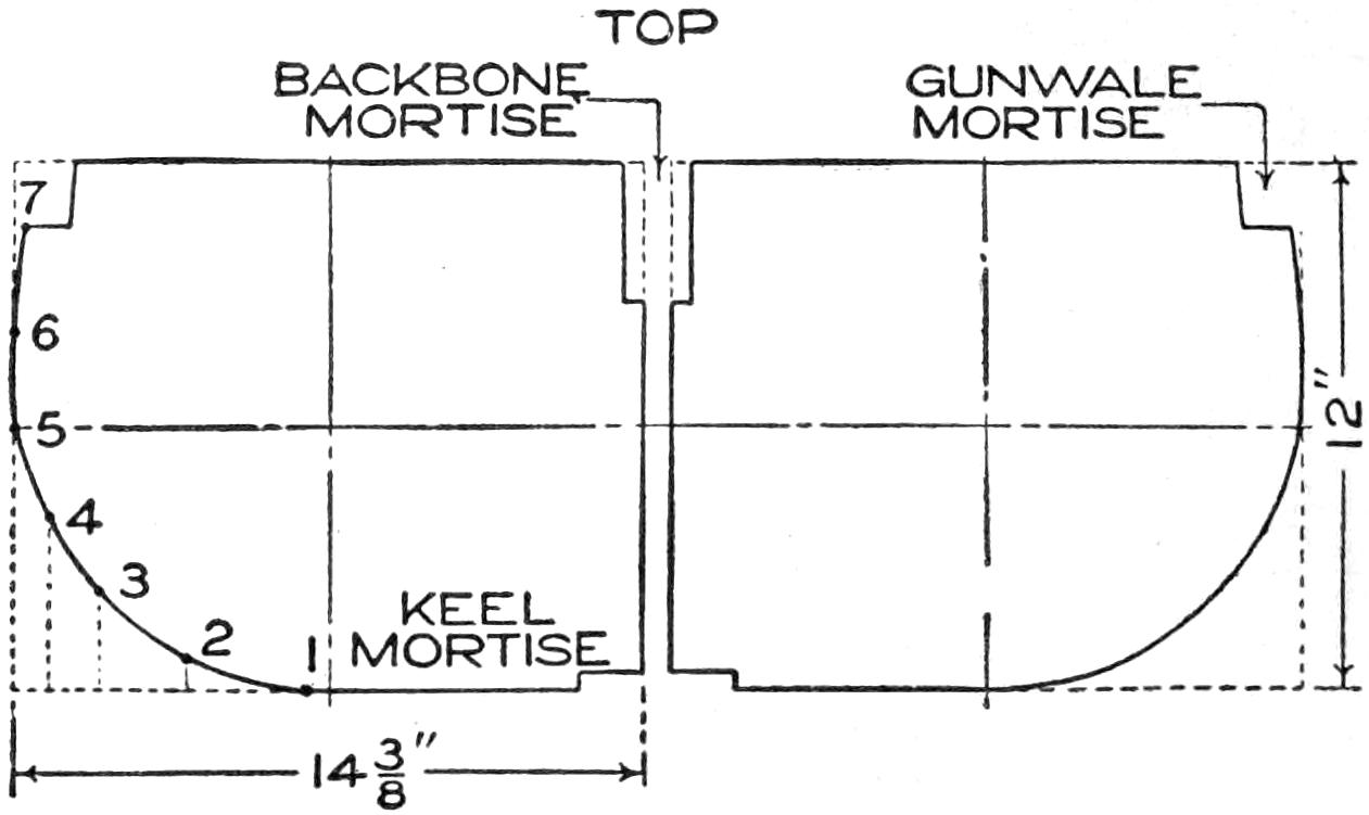
Fig. 4
This Mold is Located near the Centre of a Canoe and
is Made a Trifle Wider
Mold No. 4 is placed amidships in the center of the canoe and only one complete mold is required, as shown in Fig. 5. To make a pattern draw a rectangle 15 in. long and 12 in. wide, and divide it into four equal parts as before. From the No. 3 mold pattern trace in the mortises for the gunwale, backbone, and keel. Lay the rule on the bottom outside line and measure 2 in. from the center line to the left at D and turn the rule at right angles and[80] measure off ⁵⁄₁₆ in. inside of the bottom line and make dot 1. Measure, from D, 1¹⁄₂ in. to E, turn the rule up and measure off ⁵⁄₈ in. inside the line and make dot 2. The dot 3 is 1¹⁄₂ in. farther to the left and 1¹⁄₄ in. inside the line and dot 4 is 1 in. to the left of 3 and 2 in. inside of the line. The dot 5 is 1¹⁄₄ in. to the left of dot 4, and 4 in. inside of the bottom line, which will bring it ¹⁄₄ in. inside of the left vertical side line. At a point 2 in. above dot 5 make dot 6 on the outside vertical line and 1¹⁄₄ in. above it make dot 7. The space between dots 6 and 7 gives the widest part of the correct bilge curve. Exactly 3³⁄₄ in. above dot 7 and ¹⁄₄ in. inside of the vertical side line make dot 8, which marks the beginning of the bilge curve above the water line and at the gunwale mortise. The curve of the canoe floor is quite flat, but not exactly a straight line. Lay the rule on the bottom line and measure up, on the inner edge of the keel mortise, ¹⁄₈ in., then 2¹⁄₂ in. to the left make a mark, F, ¹⁄₁₆ in. inside the bottom line and a pencil line drawn between them will enable one to trace the correct curve. Having cut out the pattern make two wood forms exactly alike to have it complete, as shown. After finishing the seven complete molds, fasten them securely together by nailing a couple of battens across the halves.
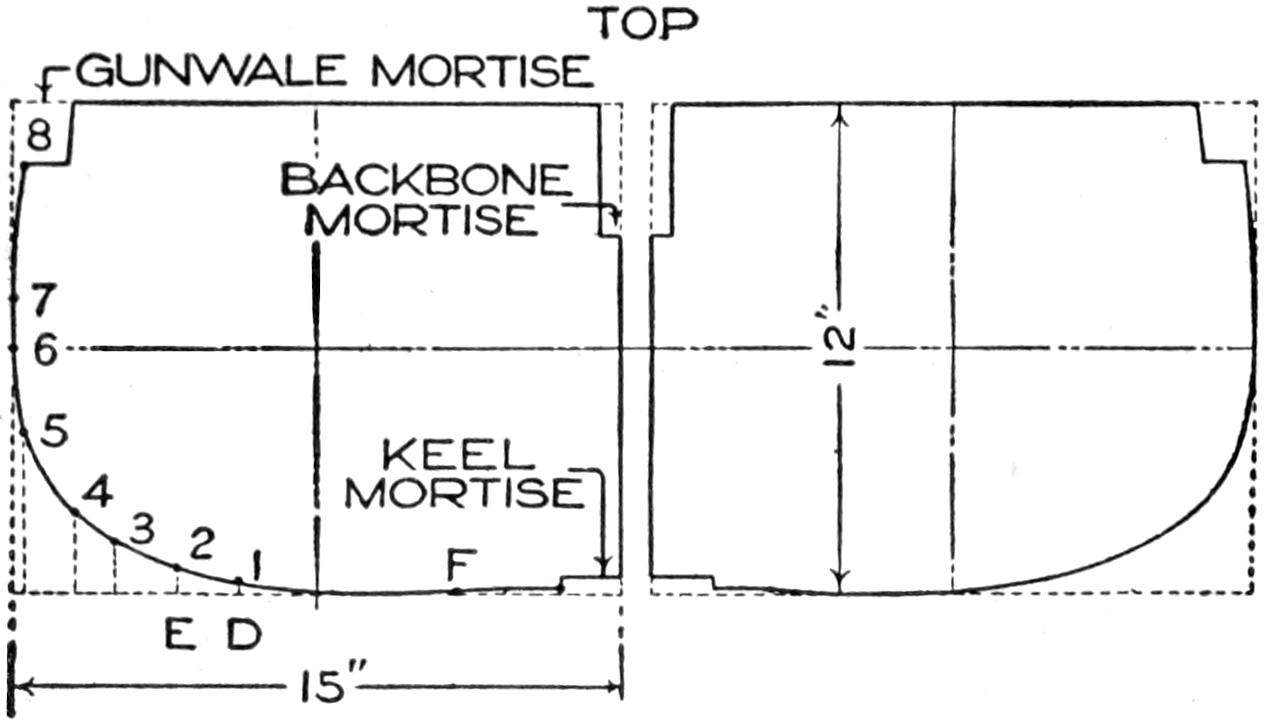
Fig. 5
This Mold is Placed Amidships, in the Center of the
Canoe, and Only One is Required
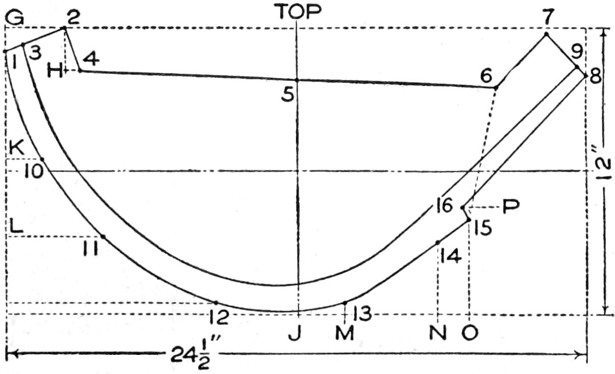
Fig. 6
Straight-Grained Material must be Selected for the
Stems, as It Is Necessary to Bend Them to Shape
The ribbands are merely strips of wood, ³⁄₄ in. wide, ¹⁄₂ in. thick, and 14 ft. long. Any cheap stuff will do because they are only used to give the correct shape of the canoe curve while building it. Six ribbands are necessary, and it is best to use eight lengths in order to make sure that the ribs are bent at the required angle and that both sides of the canoe are ribbed at the one uniform curve. For the stems ash or oak, ³⁄₄ in. square, is used, and straight-grained material must be selected since it is necessary to bend them to obtain the requisite curve.
To make the pattern for the stem mold, shown in Fig. 6, draw a rectangle, 24¹⁄₂ in. long by 12 in. wide, and divide it into four equal parts. Lay the rule on the left side at the upper corner, at G, measure down 1 in. and make dot 1. Lay the rule along the top horizontal line and measure 2¹⁄₂ in. from G and make dot 2, then draw a pencil line between them. From dot 1 measure along this line exactly ³⁄₄ in., and make dot 3. From dot 2 measure straight down 1³⁄₄ in. to H, turn at right angles and measure off ⁵⁄₈ in. to the right and make dot 4, and make a pencil line from 2 to 4 as shown. From dot 2 lay the rule parallel with the top horizontal line and measure off 9³⁄₄ in., turn at right angles and measure down on the center line 2¹⁄₄ in. and make dot 5.
Lay the rule at the upper right corner and measure down the vertical line 2³⁄₄ in., turn the rule at right angles and measure off 3⁷⁄₈ in. and make dot 6. From the upper right-hand corner measure off 1⁵⁄₈ in. and make dot 7 exactly ¹⁄₄ in. inside the top horizontal line. Again place the rule at the right-hand corner, measure down the vertical line exactly 2 in. and make dot 8. Draw the line from dot 7 to 8, and ¹⁄₂ in. from dot 8, make dot 9. This gives[81] the correct contour of the stem where it joins the splice of the keel.

Fig. 7
It Is Not Necessary to Make a Paper Pattern for the Keel, or Keelson, as the Piece is Merely Tapered
Uniformly from the Center to Ends, and It can be Drawn Direct on the Board
The greatest curve and width of the stem is at J on the lower line. To obtain the correct curve begin at the upper left corner and measure from dot 1 down the vertical line 4¹⁄₂ in. to K, turn the rule at right angles and measure 1¹⁄₄ in. inside the line, and make dot 10. The dot 11 is placed by measuring down from K exactly 3¹⁄₄ in. to L, when the rule is turned at right angles and a length of 4 in. measured off inside of the line. The dot 12 is located in the same manner by measuring 2³⁄₄ in. below L and running 8³⁄₄ in. inside the line, as shown.
To finish the irregular curve of the stem, measure from J at the center of the lower horizontal line 2 in. to M, turn the rule up and measure off ¹⁄₂ in. inside of the line, and make dot 13. The dot 14 is made by measuring off 4 in. from M to N and turning the rule to a point 3 in. inside the line, as shown. Then from point N measure to O 1¹⁄₄ in., and then measure up 4 in. to dot 15. From the dot 14 to 15 run a straight line. The dot 15 should be exactly 5 in. inside of the right vertical line.
Allowance for the beveled splice of the stem to the inside keel must now be made, and the beginning is to run a light pencil line from dot 15 to dot 6. From dot 15 measure up ¹⁄₂ in., turn the rule at P and make dot 16 exactly ¹⁄₄ in. to the left of the upright line. From dot 16 a line is run to dot 8 which completes the angle of the curve. The full curve is then easily traced in.
The inside keel, or keelson, is made exactly 13 ft. 11 in. long and 3¹⁄₂ in. wide in the center, which is, of course, amidships. It is unnecessary to go to the trouble of making a paper pattern for this because the keel is merely tapered uniformly from center to ends, and this may be drawn on the surface of the board direct. The board being 13 ft. 11 in. long and 3¹⁄₂ in. wide, it is only necessary to make cross lines exactly in the center both ways. From the center measure 1 ft. toward one end and make the width at that point 3¹⁄₂ in. Measure 1 ft. farther along, and again make the width 3¹⁄₂ in. as before. Continue in this manner, making the third station 3¹⁄₄ in.; the fourth, 2⁵⁄₈ in.; the fifth, 2 in.; the sixth, 1¹⁄₄ in., and the width at the ends ¹⁵⁄₁₆ in. This detail is well shown in Fig. 7. Bend the stem on the mold and fasten it to the keel by means of a couple of ³⁄₄-in. No. 10 screws at each end.
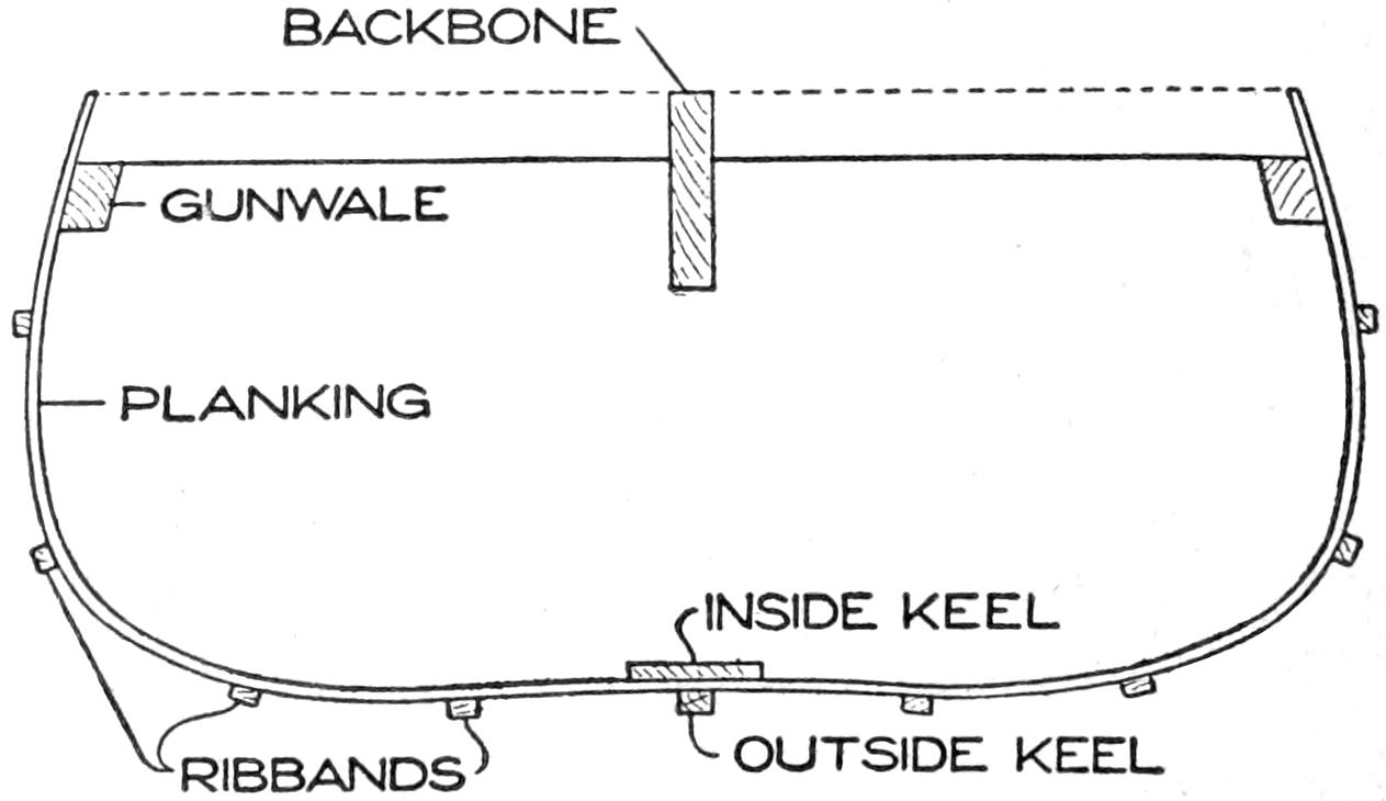
Fig. 8
The Ribs are Fastened to the Outside of the Keelson
and are Curved under the Ribbands
The ribs are best made of cedar, cut from the same material as the planking. They are 1³⁄₄ in. wide and ¹⁄₈ in. thick. It is a good plan to saw out several long lengths and cut them off as required, the length being determined by measuring from gunwale to gunwale around the curve over the ribbands. The ribs are put in under the[82] ribbands, and the thickness of the latter will allow sufficient wood for making a good fit at the sheer line. The gunwales are two straight strips, 16 ft. long, ⁷⁄₈ in. wide, and ¹⁄₂ in. thick.
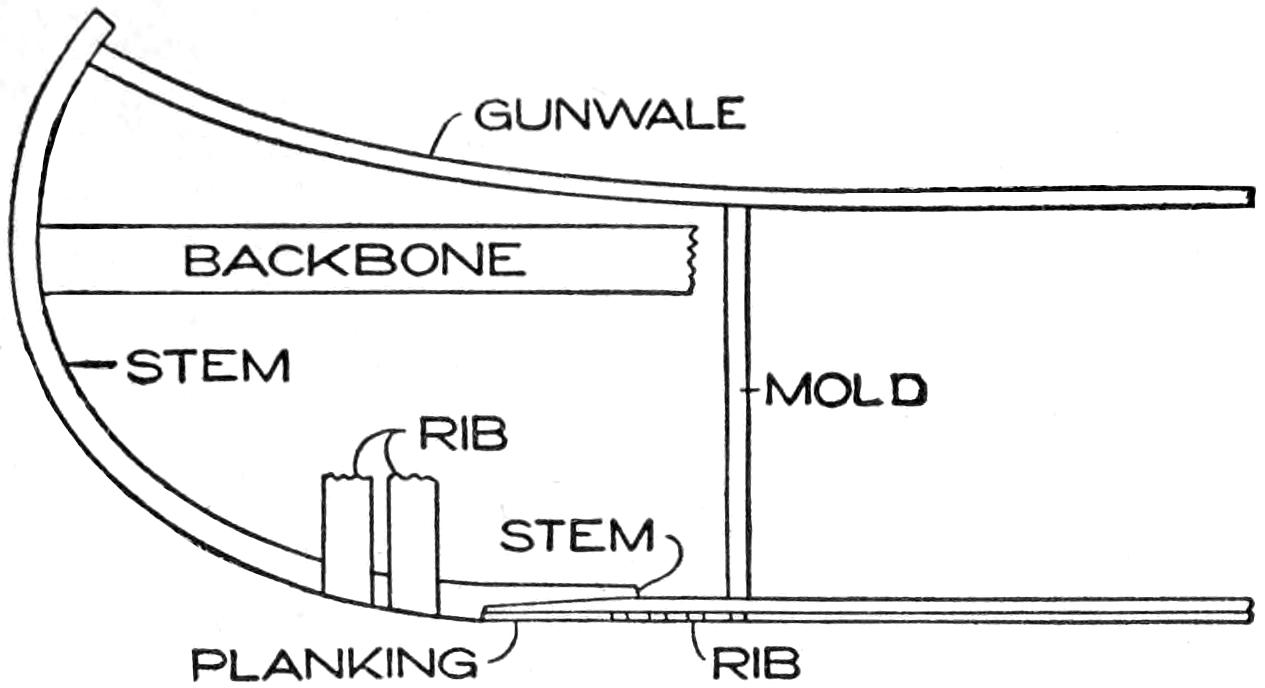
Fig. 9
The Bent Stem is Fastened to the Keel with Screws
at Both Ends
Having made all the material ready, the work of setting up the canoe may begin, and as it is built upside down, place the backbone on boxes, about 1 ft. or more above the floor, and place the molds in the numbered places on the backbone, allowing the backbone to rest upon the bottom of the mortises cut in the top of the molds. Study Figs. 8 and 9 before beginning the work of setting up the hull.
True up the molds with a square and fasten them firmly by toenailing them to the backbone. Put the keelson in place, allowing it to fit down in the mortises cut in the molds to receive it. Take particular care that the stems are a good fit with the angle of the backbone at the ends, then fasten by nailing through the top edge of the mold into the stems. As shown in the stem-mold drawing, Fig. 6, the splice where the stem fits the keelson must be cut out after it is bent into place. This is easily done by marking around the outside edge of the stem and then beveling from the inside on each side. The outer edge is left about ¹⁄₈ in. wide, and the bevel runs out to the width of the keel at the lower end.
The gunwales are next put on at the sheer line, and fastened to the molds and stems, leaving sufficient of the nails exposed to make them easily withdrawn later on. The four ribbands are then put on each side, at equal distances apart, between the gunwale and keel, or at 5-in. centers, measuring from the keel up toward the gunwale. Fasten the ribbands by driving 1¹⁄₄-in. brads through them into the mold. Measure off the keel for the ribs, which should be put on 3 in. apart, measuring from the centers. The ribs are fastened to the outside of the keelson and are curved under the ribbands. Fasten each rib to the keel by means of two ⁵⁄₈-in. copper clout nails, then spring them into place and fasten to the gunwales. Put in all the ribs in the same way, spacing them so that a rib will be placed over each mold. When all the ribs are put in, remove the ribbands, and begin planking the hull.
As a canoe is planked with ¹⁄₈-in. cedar it is easily bent to the curve of the ribs while cold, thus doing away with the trouble of steaming. Unlike heavier-planked craft the planking is not rabbeted at the stem but is nailed to the beveled surface. For strength and to give a perfectly smooth skin on which to lay the canvas, it is advisable to run the planking the full length from stem to stem. Begin by putting on the garboard strake, which is the bottom plank at the keel. Punch holes in the plank with an awl, not directly in line, but staggered from side to side along the ribs. This will prevent the possibility of splitting. Drive in the copper clout nails while the plank is kept in place with a clamp to facilitate the work. Hold a clinch iron, or any handy piece of iron, inside and clinch the nails so that the ends are well imbedded[83] in the rib on the inside. It is a simple matter to fit each plank in place, because they are merely a close fit at the edge, butted together without beveling. The number of planks required will depend upon the width, and while wider strips may be used, planking cut to the width of 3 in. is generally employed. In any case the top plank or sheer strake should be level with the gunwale from one stem to the other. When the hull is completely planked, cut off the ends of the planking to the curve of the stems and gunwales. The backbone and molds may now be taken out by sawing the backbone in two. Tack a couple of strips across the gunwales to keep the hull from sagging out of shape, then drive the nails over the sections the molds occupied, since these forms prevented doing this work before.
The seat risings are simply straight sticks, ¹⁄₂ in. square, and are fastened on the inside for the seats to rest upon. They are about 4 in. below the gunwale. Oak or ash is the best material, and the length is 14 ft. To fasten in place, first bore a small hole and then nail through the planking and ribs, and clinch on the inside of the rising.
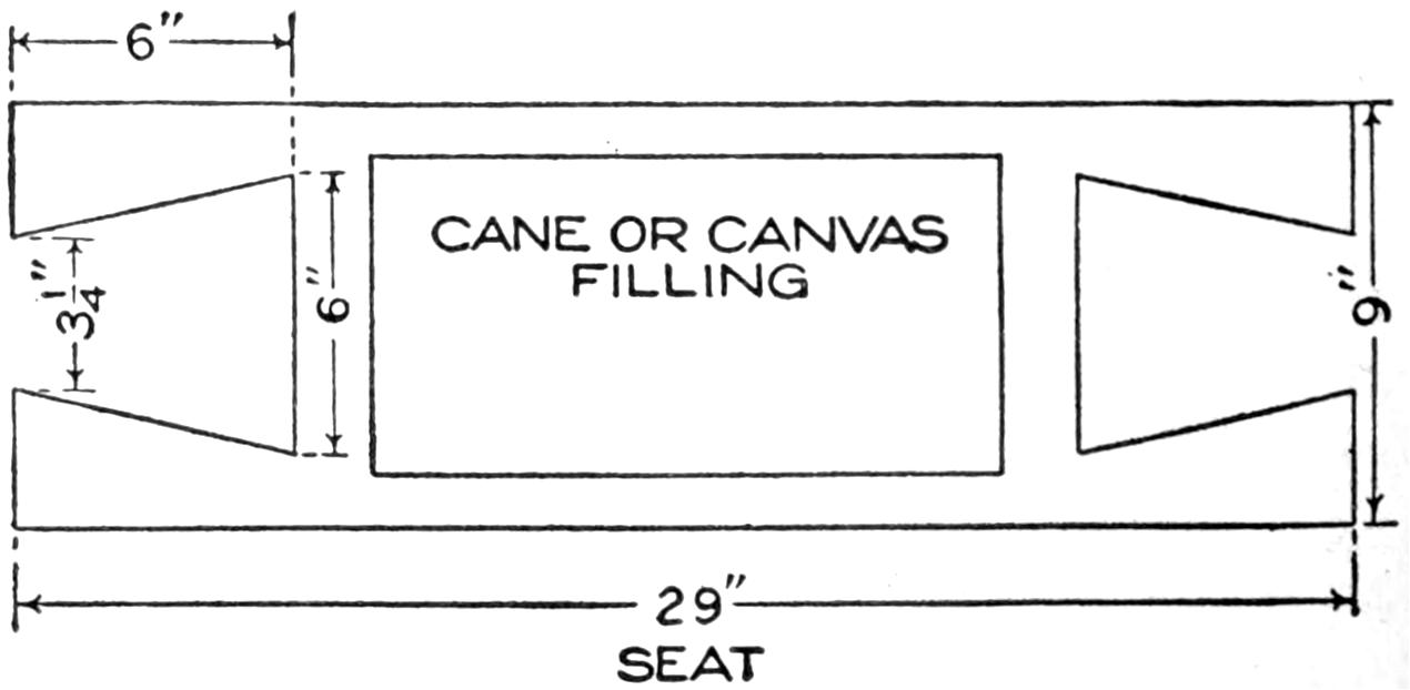
Fig. 10
The Seat Frame may be Caned, or a Canvas Seat
Tacked On, as Preferred
The seat frame is fashioned as shown in Fig. 10, and may be caned, or a canvas seat tacked on, as preferred. Many canoeists prefer to kneel, in which case a seat bar, about 4 or 5 in. wide, is run athwartships for the paddler’s back and thighs to rest against while paddling.
The deck beams are merely straight pieces, about 8 in. long, 1¹⁄₈ in. wide, and ³⁄₈ in. thick. These are notched at the ends as shown in Fig. 11, so that they will come up and wedge against the sides of the gunwales about ¹⁄₂ in. Put them in by boring a hole through the gunwale and fasten with a 1¹⁄₄-in. No. 10 screw at each end. Two are required, one at each end.

Fig. 11
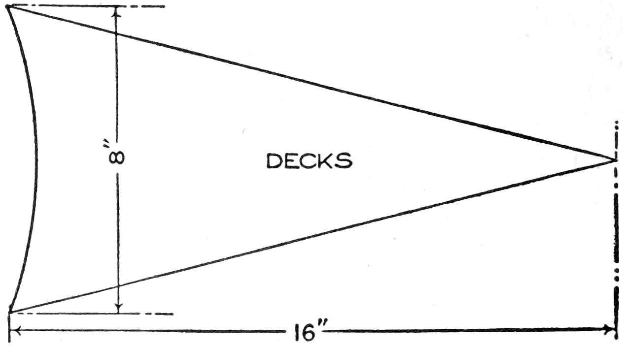
Fig. 12
The Shape of the Deck or Breast Hooks and the Beams That Support Them
The deck, or breast, hooks are made 16 in. long by 8 in. wide and of the shape shown in Fig. 12. To fasten them in place bore three holes through the deck into the deck beam and secure them with three 1¹⁄₄-in. No. 10 screws. Bore three holes along the gunwale on each side and turn three 1¹⁄₄-in. No. 10 screws into the deck.
To strengthen and stiffen the hull a center thwart, or cross bar, should be run across the canoe amidships. A piece of oak or ash, ³⁄₈ in. thick and tapering from 2 in. in the center to 1 in. at the ends, should be screwed to the lower side of the gunwale. Although not exactly essential, it is a good plan to run another thwart across the canoe just back of the forward seat, and a rear thwart some 3 ft. forward of the rear seat, or paddling bar. This will make the craft very stiff when a heavy load is carried, and likewise prevent the lightly constructed hull from sagging, or “hogging,” when stored for the winter.

Fig. 13
The Manner of Shaping the Ends of the Canvas to
Fit over the Canoe Ends
The canvas is put on with marine glue, the black kind being the best for[84] this particular purpose. Before gluing the canvas, lay it smoothly on the hull and trim so that it will fold nicely at the stems, as shown in Fig. 13. Melt the glue in a can over a moderately hot fire and spread it on one side of the canvas with a stiff brush. Of course, the glue will be too thick to spread evenly, but be sure to apply it as evenly as possible, and touch every bit of the canvas with a fairly heavy coating of glue. Lay the glued canvas in place, and iron with a moderately hot flatiron. This melts the glue, and the canvas will adhere smoothly to the planking. Finish by tacking the edge of the canvas along the edge of the gunwales, and fold the canvas as smoothly as possible at the stem, and tack in place, running the line of tacks exactly down the center line of the stem.
Fenders of ¹⁄₂-in. round molding may be tacked on to cover the edge of the canvas, or a strip, 1 in. wide, may be sawed from the same material as the planking and tacked to cover the edge by using 1¹⁄₄-in. brads every 2 or 3 in. along the edge.
The stem bands may be made from wood if desired and bent to shape, but the brass oval stem or bang iron, ³⁄₈ in. wide, makes a stronger and better finish. The wood stem band should be about ³⁄₈ in. square, and rounded on the outside. Put this on with 1¹⁄₄-in. brads and fasten the brass band with ³⁄₄-in. screws.
The outside keel may or may not be used, according to preference. It strengthens the canoe to a certain extent and keeps the bottom from many a scratch while pulling out. The usual outside keel is about 1 in. wide and ¹⁄₂ in. thick, of oak or ash, and tapered at the stems to the width of the stem bands, which are screwed on over it. The most serviceable keel is about 2¹⁄₂ in. wide in the center, and tapers to fit the bands at either end. When made of ³⁄₄-in. oak, or ash, it makes a splendid protection for the bottom of the hull, especially when the craft is used in rocky waters. Unlike the narrow keel, the flat keel makes the canoe easier to turn with the paddle, but any form of keel will add several pounds to the weight of the craft and is for this reason often omitted.
The canvas should be given a coat of shellac before the paint is applied. This makes it waterproof. Then four coats of paint are applied to fill the fibers of the canvas. To make a smooth finishing coat, rub down the second and third coats with fine sandpaper. The entire woodwork of the canoe should be finished with three coats of good-quality outside spar varnish.
A slatted grating, made of soft-pine lattice stuff, about 1¹⁄₈ in. wide and 1¹⁄₄ in. thick, will afford protection to the bottom of the canoe. For summer use this is desirable, but may be omitted on long trips and when soft footwear is worn. The grating should not be fastened to the ribs, but the parallel strips screwed, or nailed, to cross strips, curved to fit the contour of the canoe’s bottom. The grating should extend from well under the stern seat up to the stem splice in the bow, and should be nicely tapered to make a neat appearance. By fastening two or three little blocks of wood so that they will extend up between the slats, one may screw small brass buttons into these blocks to keep the slatted floor in place, thus making it easily removable when washing out the canoe.
This trick consists in borrowing a ring and wrapping it in a handkerchief from which it is made to disappear, to be found in an egg, taken from a number in a plate.
Obtain a wedding ring and sew it into one corner of a handkerchief. After borrowing a ring, pretend to wrap it in the center of the handkerchief, but instead wrap up the one concealed in the corner, retaining the borrowed one in the hand. Before[85] beginning the performance, place in the bottom of an egg cup a small quantity of soft wax. When getting the cup, slip the borrowed ring into the wax in an upright position. An egg is then chosen by anyone in the audience. This is placed in the egg cup, the ring in the bottom being pressed into the shell. With a button hook break the top of the shell and fish out the ring. The handkerchief is then taken out to show that the ring has vanished.
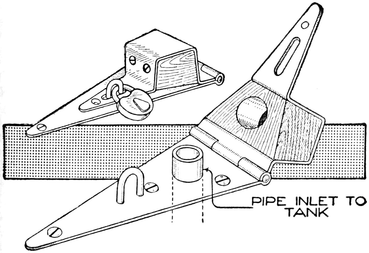
Filler-Pipe Cover Lock to Prevent the Theft of Gasoline from a Motorboat
Having trouble by thefts of gasoline from the tank in my launch, I made the following device to prevent them, which proved very effective. A strap hinge, about 12 in. long, was procured, and on one wing, near the outer end, I fastened a staple made of a large nail, and near the center a large hole was drilled to fit over the pipe, or opening, to the tank. The other wing of the hinge was bent to the shape shown, and an oak block was fastened in the bend with wood screws. A hole was bored in the block to fit over the end of the pipe. A slot was cut in the same wing at the end to receive the staple. In turning the wing over to cover the pipe end, the staple was brought into position for a padlock. After locking the device, most of the screws are covered so that it is almost impossible to remove them without taking off the lock.—Contributed by Stephen H. Freeman, Klamath Falls, Oregon.
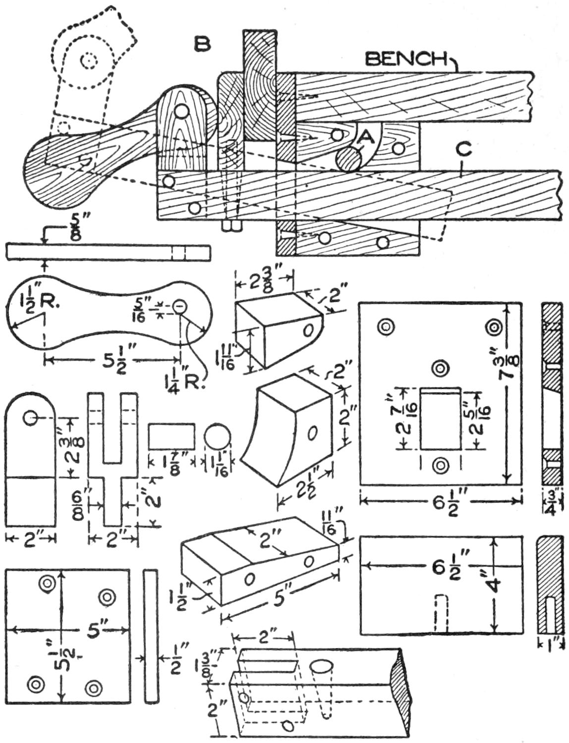
A Quick-Acting Vise Made of Hard Wood for the Home Worker’s Bench
For those who desire a quick-acting vise and cannot afford the price of a manufactured one, I designed the vise shown in the illustration. A detail is given of each part, with dimensions, so that it is not difficult to make it from hard wood. The roll A binds the vise so that it remains rigid, while the cam in front gives the necessary play, to release or tighten as preferred. The clamp jaw B is pivoted so that it swings loose, thus making it fit any surface that may not be parallel with its opposite side. In releasing the stock, the cam is first turned, and then the front part of the vise is pulled up to relieve the roll A. The front jaw can be then moved back and forth to take stock of any size desired. As soon as the stock is placed, the roll A falls into place and clamps the jaw arm C.—Contributed by J. C. Hansen, Maywood, Ill.
¶A practical vacuum will raise water 30 feet.
[86]
How To Build
A Canoe
By Stillman Taylor
PART II
Sailing the Open Paddling Canoe
Sailing and its recreations are afforded the owner of an open paddling canoe, for a satisfactory sailing rig may be provided at small cost. A regulation sailing outfit may be purchased, but it is rather costly, and if the canoeist cannot use a sail frequently, purchasing an outfit is unduly expensive. A sailing rig may be constructed even by one of only moderate skill, who will devote a few hours to it. The specifications given, if carefully followed, will enable one to make a sailing rig as serviceable as a ready-made outfit, and at about one-half the cost.
The specifications and list of material for a sailing outfit suitable for a 16-ft. open canoe are as follows:
1 piece bamboo, 1¹⁄₂ in. in diameter, 6 ft. 10 in. long, for mast.
2 pieces bamboo fishing rod, 1 in. at butt, 10 ft. long.
1 piece, cedar or white pine, 5 ft. long, 4 in. wide, and ⁷⁄₈ in. thick, for leeboard thwart.
2 pieces, cedar or pine, 28 in. long, 10 in. wide, and ³⁄₈ in. thick, for mast thwart.
1 piece, cedar or pine, 27¹⁄₂ in. long, 3¹⁄₂ in. wide, and ³⁄₄ in. thick, for mast thwart.
1 piece, cedar or pine, 5 in. long, 2¹⁄₂ in. wide, and 1 in. thick, for mast step.
8 yd. unbleached cotton sheeting, 1 yd. wide, for making sail.
30 ft. ¹⁄₄-in. cotton rope, for halyard and main sheet.
4 brass lantern-board hooks, for clamping mast thwart and leeboard thwart to canoe.
2 brass stove bolts, 3 in. long and ⁵⁄₁₆ in. diameter, with washers and thumb nuts, for clamping leeboards at desired angle.
1 brass single-boom jaw for canoe, 2 in. long, for keeping boom on mast.
3 brass screw eyes, 1¹⁄₂ in. long with ¹⁄₂-in. eye, one for halyard, two for spars.
1 brass split ring, 1¹⁄₂ in., for fastening ends of spars together.
1 brass “S” hook, 1³⁄₄ in. long, for fastening ends of spars.
In converting the paddling canoe for sailing, it is desirable that it be unmarred, as far as possible. The rig described represents the result of experiments with various arrangements, and has been found to be safe and convenient. The original outfit has been in use for six years and will still serve for some time.
The lateen rig is best for an open canoe, because a shorter mast is required for the same sail area. An open craft is less suited for carrying sail than one which is decked fore, aft, and amidships. It is not safe to rig a canoe too heavily, and the rig described has been found to be well proportioned.
Bamboo is best for the mast, because it is lighter and tougher than a solid wood spar of the same dimensions, and is readily procured. Dealers in rugs use bamboo of 1¹⁄₂ to 2-in. diameter on which to roll carpets, and it may usually be purchased of them.
Cut the bamboo to a length of 6 ft. 10 in., and whittle a wooden plug, about 3 in. long, tapering it so that it will wedge firmly inside, taking care not to split the cane. Bore a small hole through the cane 2 in. from the top, plug it and fix a screw eye into the plug. Drive small brads through the cane into the plug to prevent the former from splitting. A brass ferrule fitted over the end of the bamboo will make a strong and neat finish.
The sail is made in the form of a triangle and measures 9 ft. on each side. It is best to have it sewed on a machine. The sail is bighted with parallel strips, or folds, ¹⁄₂ in. wide, spaced 6 in. apart, as shown at the left in the illustration. First cut the canvas to the approximate size and shape by laying the spars over it and marking the outline with a pencil. Next sew the separate widths together, lapping one edge over the other about ¹⁄₂ in., and sewing close to both edges. The bights or folds run at an angle and parallel with the loose ends of the leech of the sail. The sail should then be reinforced at the corners by sewing segments of cloth at these points. Along the edges which are to be lashed to the spars, fold over a strip of canvas and sew it to make a 1-in. hem. Run a ¹⁄₂-in. tape into the fold along the leech while sewing the hem. This tape is fastened to the spar at each end, to take up the slack caused by the stretching of the sail after use, thus preventing that bugbear of sailors—a flapping leech.
[87]
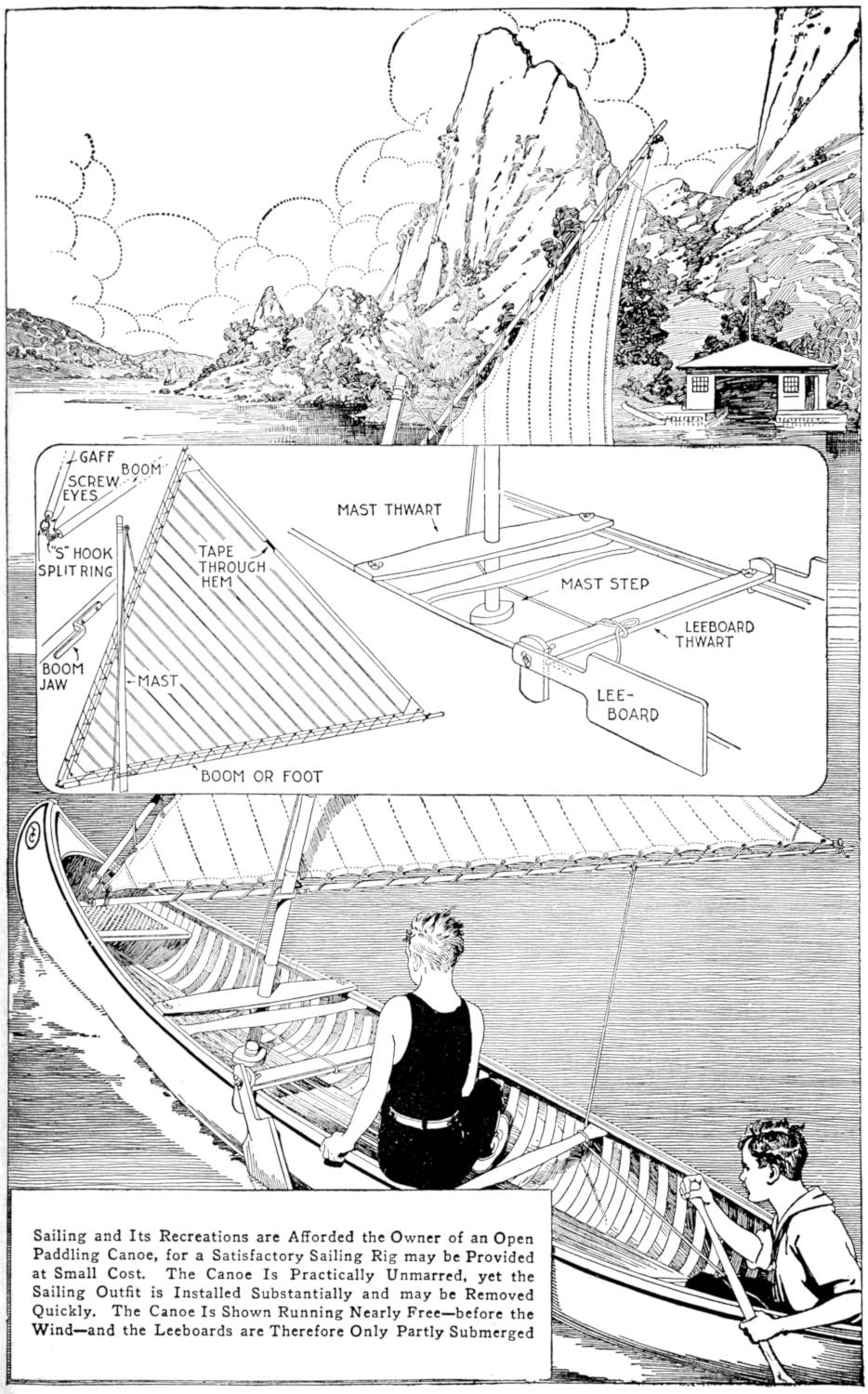
Sailing and Its Recreations are Afforded the Owner of an Open Paddling Canoe, for a Satisfactory Sailing Rig may be Provided at Small Cost. The Canoe Is Practically Unmarred, yet the Sailing Outfit is Installed Substantially and may be Removed Quickly. The Canoe Is Shown Running Nearly Free—before the Wind—and the Leeboards are Therefore Only Partly Submerged
[88]
The mast thwart is made as shown at the right in the illustration, and has a hole cut in the center to fit the mast. It is also provided with two lantern-board hooks, one at each end, with which to clamp the thwart to the gunwales. The mast is supported at the bottom by means of the mast step, which is a block of wood, shaped as shown to give a neat appearance. It is fastened to the grating, or to the ribs if no grating is used.
The leeboard thwart is also shown in the sketch, at the right. The short upright ends are set at an angle so that they conform to the curve of the canoe and wedge the thwart into place immediately aft of the mast. The ends are grooved to fit the thwart and fastened with screws. A carriage bolt is fitted through each end piece and provided with a wing nut, which holds the leeboard in place on each side. The leeboards may thus be adjusted at the desired angle by fixing them with wing nuts. No dimensions are given, for it is obvious that they will vary on different styles and sizes of canoes. A finish in keeping with that of the canoe should be applied. Smooth all the work as carefully as possible with sharp tools and sandpaper it lightly. Three coats of spar varnish will give a satisfactory finish.
The sail is hoisted by running the halyard through the screw eye at the top of the mast, until the gaff spar is close to the mast top, as illustrated.
The boom jaw is fastened on the boom, with the open end 18 in. from the forward end of the boom. This will permit the forefoot of the sail to extend forward of the mast. By tying the halyard at various points along the gaff, the point of balance may be found. For the sake of safety the halyard should not be tied to the forward thwart, but run under it to the stern within easy reach of the canoeist. The main sheet should never be made fast, but the rope merely looped around the thwart and held in the hand or beneath the foot, so that it may be released quickly if a puff of wind should strike the sail.
Steering is done with a paddle. This method is more convenient than a rudder where the single sail is used. The paddle is always used on the lee side—away from the wind—and the wake keeps the blade close to the side of the canoe, without much effort on the part of the person guiding it. When turning about make the regular paddling stroke, but finish it by thrusting the blade of the paddle away from the canoe. This will tend to keep the canoe in its course, and the paddle will not be drawn across the wake, which would affect the headway of the craft.
The lower the weight is placed in a canoe, or boat, the greater will be its stability. Hence, in sailing a canoe, sit on the floor of the craft, and when turning about, turn against the wind and not with it. The experienced canoeist can shift his course readily, but the novice must be cautious, even in a moderate breeze. It would be well to sail in shallow water and to wear only bathing costume when learning to sail a canoe. When tacking and sailing close-hauled the leeboard is the most effective, but as the boards are thin both may be kept down without greatly reducing the speed. When running before the wind both boards may be raised to give the greatest speed.
¶Paint may be readily removed from windows by applying a cloth dipped in hot vinegar or acetic acid. This applied to brushes will soften them.
[89]
How To Build
A Canoe
By Stillman Taylor
PART III
Fitting a Motor into a Paddling Canoe
A stanchly built canoe of sufficient length and beam may be converted into a light, serviceable, and convenient power boat by the installation of a light-weight motor of about 2 hp. While the craft thus becomes less available for shallow waters and cannot be used so readily on trips where portages are necessary, a power canoe has advantages in that longer trips may be undertaken with less regard for weather conditions. Greater speed and the fact that physical power need not be expended also increase the value and range of operations of such a craft.
Unless a motor of extremely light weight is procured, a canoe of frail construction and less than 16 ft. long is not likely to stand the jar of the driving mechanism. The canoe illustrated in the page plate is 18 ft. long, of 36-in. beam, and strongly planked, decked, and braced. A canoe of even broader beam would tend to give more stability in rough water, and if it is desired to transport heavy camping packs, or other material, in the craft, this factor should be observed particularly. Likewise, the depth and draft must be considered, as the carrying capacity and seaworthiness of a canoe depend in part on these factors. The fitting of the various parts of the mechanism and accessories must be done with the aim of balancing the load evenly. If properly disposed, the weight of these parts should tend to lower the center of gravity of the canoe, thus rendering it more stable.
The actual work of installing the motor and fittings should be preceded by careful planning and the making of a full-size diagram of the stern portion of the canoe as rebuilt. Too much care cannot be taken in this work, as, if it is neglected, the craft may be rendered unsafe, or the motor and fittings may not operate satisfactorily. The motor should be set in the stern, as shown in the illustration, as this will permit the use of a minimum of shafting and other fittings which must be accommodated. The exact location of the motor may vary with canoes and engines of different types. This should be tested out by placing the motor in the canoe and noting the effect on its balance in the water. For a canoe of the dimensions indicated, and a light-weight motor, 5 ft. from the stern is a satisfactory position. The motor should be placed as low in the canoe as possible, allowing the flywheel and crank case sufficient clearance below.
A convenient method of operation is as follows: Place the canoe on boxes, or sawhorses, taking care that it is properly supported about 2 ft. from the ground, or floor. Take measurements directly from the canoe, or part to be fitted, whenever convenient. Procure two sheets of paper, 30 in. wide and 7 ft. long; mark one “diagram” and the other “templates,” and use the former for the full-size detail and the other for the making of templates for curved or irregular parts.
Begin the diagram by drawing the base line AB, Fig. 3. This is the lower line of the engine bed and the upper surface of the ribs. Draw the line CD perpendicular to the base line, and 18 in. from the left end of the sheet. The[90] point C is the center of the stern end of the driving shaft. The dimensions of parts are not given, except in special instances, since they must be obtained from the particular canoe and other parts entering into the construction. Indicate the layer of ribs E, the planking F, and the keel G. Using the template sheet, cut a template or pattern for the curved stern. This may be readily and accurately done by fixing a straightedge to the keel and permitting it to extend to A. Rest the long edge of the sheet on the straightedge when fitting the template to the curve. Use the template as a guide in marking the curve on the diagram, as at HJ. The curve K, of the stern decking, may be indicated similarly.
Determine the distance the motor is to be set from the stern and indicate it by the perpendicular line L. Measuring from the base line, indicate the height of the center of the motor shaft from the floor, as at M. This should be made as low as possible, permitting sufficient clearance for the flywheel and the crank case. Draw a straight line from C to M, which will thus indicate the center line of the driving shaft. This line is fundamental in determining the dimensions and placing of certain parts and fittings, and should be established with extreme care. The size and exact position of the engine bed N may now be indicated. Its dimensions, given in detail in the perspective sketch, Fig. 5, are suggestive only. They may be varied in order to provide proper bearing on the floor, and so that the bolts holding the bed may pass through ribs. The cross brace at the forward end is important, and should be fitted carefully over a rib. The upper line of the engine bed must not be confounded with the center line of the shaft, for in many engines they are on a horizontal line when viewed from the forward end, yet not necessarily so. The slant of the engine bed must be made accurately, as any deflection from the angle of the center line of the shaft will disarrange the installation.
The shaft log O may next be indicated and a template made for use in guiding the bit when boring the hole for the shaft through it. The template used for the curve HJ may be altered by drawing the shaft log on it at the proper place. The point P, from which the bit is to be started when the shaft log is fixed into place, should be indicated and the center line of the shaft extended to Q, may then be used as a guide for the bit. If the homemade type of bearing R is used, it should be indicated on the diagram. A metal bearing may be made, or a suitable one obtained from dealers in marine hardware. In the latter case it will probably be necessary to block up the bottom of the canoe in order to provide a flat, horizontal bearing surface for the bearing flange.
The rudder and other parts, which are not directly connected with the motive-power unit, may be indicated in detail on the diagram or be made from sketches of a smaller scale. Paper patterns, made full size, offer a convenient method of outlining the parts of the engine bed, the rudder, and other irregular pieces. When the diagram is complete, measurements may be transferred directly from it without reducing them to figures, and, wherever possible, parts should be fitted to it.
The shaft log, shaft bearing, and engine bed may be made of oak, or other strong hard wood. It will be found desirable to have the engine bed complete before an attempt is made to fit the shaft and its connections. It is made of 1¹⁄₂-in. stock, bolted together with lag screws and fixed firmly into the canoe with bolts. The heads of the bolts should be provided with cotton and red-lead packing, and care should be taken that the bolts pass through ribs.
The shaft log should be fixed into place before it is bored. Bolts may be passed through it and fastened on the inside if there is room for drawing up the nuts in the stern. Large screws may be used to aid in the fastening and smaller screws may be used from the inside. The lower rudder support will also aid in holding the log in place, and the iron straps S, Fig. 3, will insure its rigidity. This is an important point in the construction, as if the log is not fixed positively, the thrashing of the propeller will soon loosen it.
[91]
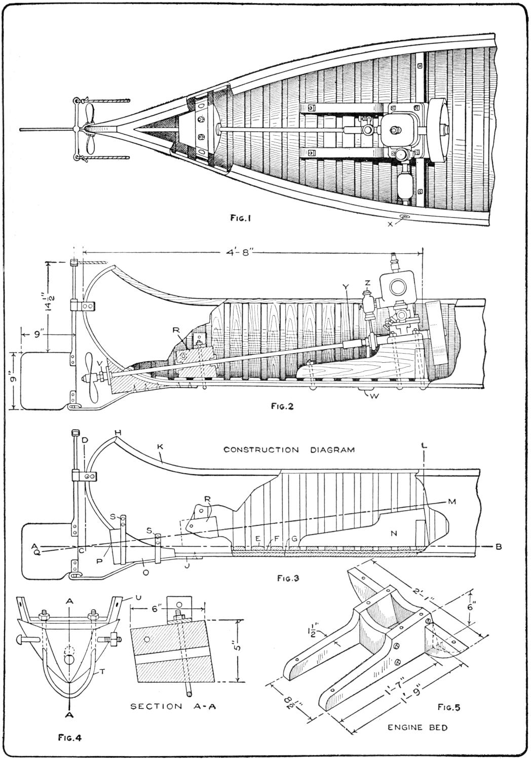
Fig. 1
Fig. 2
Fig. 3
Fig. 4
Fig. 5
A Light-Weight, Two-Horsepower Motor Installed in a Stanch 18-Foot Canoe will Increase the Range and Utility of Such a Craft; the Construction Shown Is Simple and within the Capabilities of a Careful Novice of Fair Mechanical Skill. A View of the Stern from Above is Shown in Fig. 1. The Engine is Shown Mounted on the Engine Bed, and near the Stern the Shaft Block is Shown. A Partial Sectional View is Shown in Fig. 2. The Relation of the Engine and Bed, Shaft and Fittings, Shaft Block, Shaft Log, and Rudder are Shown. The Construction Diagram, Fig. 3, is Described in Detail in the Text. A Larger-Scale View and a Section of the Shaft Block are Indicated in Fig. 4, and Fig. 5 Illustrates the Engine Bed with Dimensions and Fastening Holes
[92]
A detail of the shaft bearing R is shown in Fig. 4. The hole to receive the shaft must be bored accurately, and the use of the template, as with the boring of the shaft log, is advisable. Flanged metal bearings are provided to take up the wear in the bearing block. The method of fastening the block, as shown in the detail view, insures a rigid bearing with a minimum of holes through the bottom of the canoe. A U-bolt, T, binds the double angle brace U and the block firmly to the keel. The angles of the brace are fixed into the sides of the canoe with bolts, and a bolt at the stern end of the block supports it further. The block should be placed so that it will bear on three ribs and must be fitted to the curve of the canoe.
The rudder is made of sheet metal supported on a rod or pipe. Its general dimensions are shown in Fig. 2. The fan of the rudder is riveted to its supports and rests in a bearing strip of ¹⁄₄ by 1-in. strap iron, which is shaped as a guard for the propeller. The upper bearing of the rudder post is formed from a strip of iron, bolted to the stern, and the upper guide bar, to which the ropes are attached, is cut from an iron strip.
The propeller is 8 in. in diameter, but may be installed of a size suitable to the power, speed, and type of the motor used. The stuffing box V, Fig. 2, the bearings for the bearing block R, the intake strainer W, the exhaust outlet X, Fig. 1, and the shaft coupling Y are all of manufactured types that may be purchased of marine-supply houses.
The intake strainer W is placed in the bottom directly below the pump Z. The exhaust outlet X is placed above the water line, and a muffler should be installed to avoid noise from the exhaust explosions. The exhaust may be conducted under water or to a point near the stern. No indication is given for the placing of the gasoline tank, the supply pipes, electrical-energy source, and wiring. The tank may be placed in the stern of the canoe high enough to provide a good flow. A magneto may be used to give current for the sparking circuit, or batteries may be provided. They may be placed at any point convenient, and should be incased in a waterproof container.
In assembling the parts care must be taken not to wrench the shaft or other pieces out of line, and in general, it is well to fix nonadjustable parts solidly when they are fitted into place. This applies particularly to the engine bed and the shaft log. The bearing block may be adjusted vertically by adding packing, or by reducing the lower surface. The rudder and its fittings may be made in regular course, but should not be fitted until the power unit and driving mechanism is in place finally. The propeller may be protected from possible injury by laying it aside until needed. All the openings in the hull through which bolts or other fastenings are placed should be packed with red lead or other waterproof packing. The working parts and finished metal surfaces should be oiled or greased thoroughly as the parts are assembled, and the unfinished metal parts painted with red lead. This will protect them from moisture and aid in the smooth operation of the mechanism.
Many experimenters have occasion to use a fluorescent screen, particularly those interested in X-ray work. Such a device is quite expensive if purchased, and may be made as follows:
Mix 1 oz. each of common salt, sodium tungstate, and calcium chloride. Place the mixture in a crucible and heat it dull red in a coal fire, for several hours. It will melt into a clear liquid, and should then be removed and permitted to cool. The liquid will crystallize into a hard glasslike mass. Break this out of the crucible and crush it into small pieces. Put them into a[93] jar of clear water. The sodium chloride resulting from the chemical change by heating, will gradually dissolve and the calcium tungstate will fall to the bottom in fine crystals. Wash this precipitate until all trace of the salt disappears; then pour the crystals upon a sheet of filter or blotting paper to dry. After drying, place them in a mortar and grind them to a fine powder, when they will be ready for use.
To make the screen proper, procure a piece of thin white cardboard of the size desired. The calendered board known as three-ply is satisfactory. Paint the cardboard on one side with a thick solution of gum arabic in water, or better still, with celluloid dissolved in amyl acetate. Permit the gum to become “tacky” before dusting with the chemical. The latter process requires care, to produce an even layer on the cardboard, and it is advisable to practice with ordinary salt before attempting it on the cardboard for the screen. The calcium tungstate should be placed in a dry jar, and a piece of fine muslin fixed over the mouth of it. The chemical may be dusted over the surface with this sieve jar.
Shake off the superfluous crystals and permit the screen to dry thoroughly. Fasten a piece of mica, or sheet celluloid, over the sensitized surface to prevent damage to it. Mount the sensitized cardboard in a wooden frame of suitable size and arrange a hood around its edges to cut out unnecessary light. The sensitive side of the screen is, of course, held toward the observer when the apparatus is used.—Contributed by Chester Keene, Hoboken, N. J.
Fences which inclose pastures for hogs, or other smaller animals, are usually stretched to give rigidity and strength. Often the adjustment of the wire, after being put into place, causes it to rise from the ground between the fence posts, permitting the animals to escape. An effective method of holding the wire close to the ground is shown in the sketch. A peg, notched near its upper end, is driven into the ground so that the lower edge of the wire mesh is held fast in the notch.—Contributed by O. B. Laurent, New Roads, La.
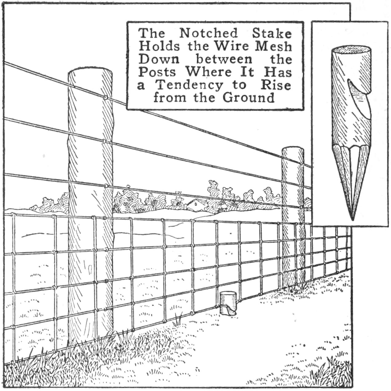
The Notched Stake Holds the Wire Mesh Down between the Posts Where It Has a Tendency to Rise from the Ground
Those who have occasional work to be done with a jig saw will find the simple device shown in the sketch convenient. It provides a table for sawing light work. By holding it in a vise, as shown, a rigid support may be had. The table is made of a rectangular piece of ³⁄₄-in. wood, 8 in. wide and 10 in. long. At one end, a strip, 1 in. square, is attached for clamping in the vise. The other end is notched to provide a place for the saw while in use.—Contributed by Victor A. Rettich, New York, N. Y.
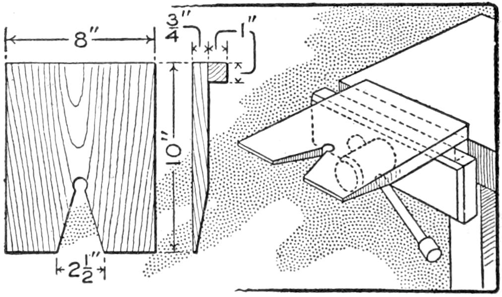
The Jig-Saw Table Provides a Rigid Support for Light Fretwork
[94]
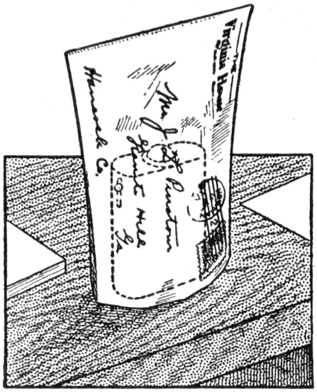
The traveling man who “lives in a suitcase” and at the same time wishes to enjoy the pleasures of amateur photography sometimes experiences difficulty in developing films in a hotel room. Soup plates borrowed from the steward, or even the bowl pitcher and the ice-water pitcher in the room, can be used for development, but it is very hard to improvise a ruby lamp. My emergency lamp is a small vest-pocket flash lamp over which two yellow envelopes, one inside of the other, are slipped, as shown. The lower edges are cut perfectly square and rest on the table, or shelf, in the closet, and all white light is excluded. At night, the shades may be drawn, and a yellow-paper sack may be tied around the electric light.—Contributed by J. L. Pinkston, Granite Hill, Ga.
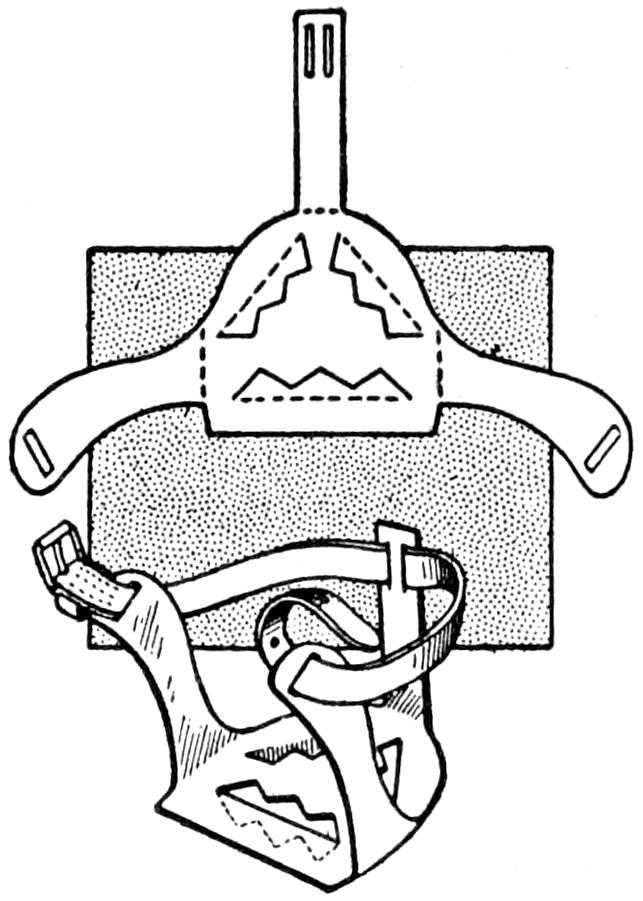
The illustration shows a one-piece ice creeper for the heel of a boot or shoe. It is made from sheet steel with the arms bent up to receive a strap for buckling it in place on the boot heel. The zigzag cuts in the bottom part are turned down for engaging the ice.—Contributed by Chas. S. Snell, Lewiston, Me.
¶In machine work a way must be provided for removing dowel pins before they are driven in place.
Dissolve ¹⁄₂ oz. of orange shellac in ¹⁄₂ pt. of alcohol, and add 1 teaspoonful of Venice turpentine, the same quantity of raw linseed oil, and 2 oz. tincture of benzoin. Shake well, and set in a varnish can in hot water.
Soak the coiled line in the varnish for two hours, then hang it up to dry. Thin the varnish with alcohol, and repeat the dipping. When the line is dry, rub it down well with a wool rag greased with tallow. Silk lines treated in this manner are pliable, and the fibers of the silk are so united by the varnish that the strength of the line is almost doubled.
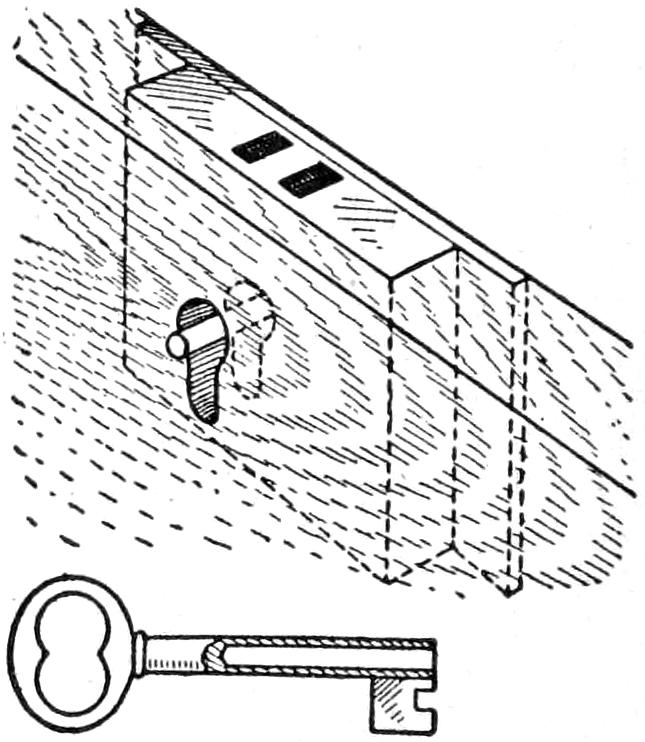
As a rule, ordinary chest locks cannot be relied upon, since almost any kind of a similar key will unlock them. I found a good remedy by taking out the pin on which the key fits, and making a new one twice as long as the one removed, then drilling a hole in the key deep enough to fit over the new pin. In case the pin extends too far, a piece of wood block, with a hole in it to admit the key, can be fastened over it to prevent bending the pin. No ordinary key will pass on the pin far enough to turn the lock.—Contributed by Chas. G. England, Washington, Pa.
Keep the supply of screws in a box containing a small amount of powdered soapstone. Shake the box occasionally, and the screws will be dusted with the powder, which acts as a lubricant. This is a much cleaner and more convenient method than the ordinary one of rubbing each screw on a bar of soap before driving it in hard wood.
[95]

Paddling Your Own Canoe
by
Stillman Taylor
PART I—
Kinds of Canoes
The charm of the birchen canoe has long been sung in verse and prose, and while the bark that the Indian used has been supplanted by a more perfect type of modern manufacture, the popularity of this, the most graceful of water craft, has increased with years, until today we find the canoe the choice of thousands of recreation seekers who paddle about in park lakes and quiet streams, or spend their vacations in cruising down rivers and other attractive waterways—sometimes within the environs of towns and villages, and again dipping paddles in the wilderness streams of the far north. True, the modern canoe is a distinct product of the twentieth century, and while it is so largely used at summer resorts, it nevertheless retains all the good points of the old, while embodying numerous improvements which fit it even better for wilderness travel than the Indian model after which it was patterned. The noteworthy increase in the number of canoeists in the past dozen years is good evidence that this natty craft is fast coming into its own, and as more and more outdoor men and women understand its possibilities and limitations and become proficient in handling it, the long-rooted fear and distrust with which the uninformed public regard the canoe, will pass away. As a matter of fact, accidents ever follow in the wake of ignorance and carelessness, and while there are very few expert gunners injured by firearms, and still fewer experienced canoeists drowned, there are numerous sad accidents constantly occurring to the reckless and foolhardy, who do not know how to handle a weapon, nor understand the first thing about paddling a canoe. Let us consider then, the practical side of the subject, the choice of a suitable canoe and the knack of handling it in a safe and efficient manner.
If one would experience in full measure the many-sided charm of paddling, he should get a good canoe. Unlike other and heavier water craft, the canoe is a lightly balanced and responsive conveyance, which may be cranky and dangerous, or safe and stable, according to the model, the skill of the builder, and the dexterity of the paddler. There are canoes and canoes, of varying models and sizes, and constructed of many materials, and while all may serve as a means of getting about in the water, the paddling qualities include numerous little idiosyncrasies which serve to differentiate canoes as well as men. In fact, this light and graceful craft may be properly viewed as the highest type of boat building, since it must be fashioned strong but light; it must be steady when going light; capable of carrying[96] comparatively heavy loads; draw little water, and it must be honestly constructed of good material to stand up under the hard usage which every canoe is subjected to, whether used for summer paddling, or upon long hunting and shooting trips.
Three types of canoes are in common use by experienced canoeists, the birch-bark, the all-wood, and the canvas-covered cedar canoe. The birch-bark, by reason of its rougher workmanship, is slow under the paddle, is easily injured, and it grows heavier and more difficult to handle every time it is used. The all-wood canoe is most expensive to buy, and though swift under the paddle, is too easily injured and too difficult to repair for rough and ready use. The cedar-planked canoe which is covered with filled and painted canvas is for many reasons the best all-around craft-attractive enough for park use, and stout enough for use in rapid water and for cruising in northern lakes and rivers.
The Indian-made birch-bark canoe costs about $1 a foot and is fashioned of birch bark over an ash, or spruce, frame. The bark is not nailed to the frame, but is sewed together with boiled spruce, or tamarack, roots, split to a suitable size. To give the proper shape to the canoe a double row of stakes are firmly planted in the ground and the spruce frame is sprung between them. The bark is put on inside out, and the work of sewing together is done while the bark is fresh, or immediately after it is stripped from the tree. The seams are afterward made water-tight by smearing well with spruce gum, which hardens quickly and makes a fairly good joint. The Indian model is a good one so far as the freeboard, width of beam, and flaring stems are concerned, but the curved bottom makes it extremely cranky and dangerous for the novice to handle. Be sure to see that the birch-bark canoe is fashioned with a flat, straight bottom, which makes the craft steadier and less inclined to veer about under the stroke of the paddle. In an expert’s hands the round bottom will be found a decided advantage, making it faster to paddle and more easily turned and steered in swift and rough water. Many prefer the three-piece bottom, but the bottom made of a single piece of bark is stronger and less likely to open up and leak. All birch canoes will warp and twist somewhat, and it is practically impossible to find one that is straight and true. The birch-bark canoe has many limitations and not a few weaknesses, but if one has the good luck to find a good one, and treats it fairly, it will prove a safe and dry craft for many hundreds of miles’ travel. Of course, one must carry a kettle of pitch for making repairs, and be content to travel somewhat slower than with modern canoes, but this may not be a disadvantage. Birch canoes have no seats, as the Indian kneels when paddling, but a low thwart, or seat, is easy to put in at the bow and stern, if one prefers the white man’s paddling position.
This type of craft is much used in Canada along the St. Lawrence River, and to a much less extent by American sportsmen, owing to its higher cost, and its tendency to break and cause a leak. Of course, the all-wood canoe is a good craft, but everything considered, there can be no question in the minds of canoeists who are acquainted with all types of canoes, that the all-cedar or basswood craft is less dependable than the canvas-covered cedar canoe. The Peterborough type—so called from a Canadian city of this name where many wood canoes are made—with its relatively low ends and straight sides with but little sheer and tumble home, is the model commonly used by practically all manufacturers of the all-wood canoe. While a boat of this kind can be, and often is, used in rough-water lake paddling as well as in wilderness travel, the all-wood canoe is better suited for club use, and in the wider and more quiet-flowing streams and lakes.
[97]

The Best All-Around Craft, for Two Men and a Reasonable Amount of Camp Duffle, Is a Canvas-Covered Cedar Canoe, 16 Feet Long, 32-Inch Beam, and 12 Inches Amidships, Weighing About 60 Pounds

The canvas-covered cedar canoe, when rightly made of the best material, is by all odds the best paddling craft afloat, being strong and light, with a hull so smooth that it is swift to paddle, while the mode of construction makes a very stiff craft, which will not warp or twist out of shape. Moreover, it will stand a vast amount of hard usage and abuse, while repairs are quickly and neatly done by the stream side. In the making of a first-class canoe of this type, the ribs are first steamed and then bent and fitted over a solid form; cedar being used for the ribs and planking; spruce for the gunwales, and white ash, or oak, for the stems and thwarts. In a canoe built according to my instructions, each plank runs to the full length of the craft and all are beveled and lapped together, thus making a perfectly smooth and almost water-tight canoe, before the canvas is cemented on its surface. The canvas is thoroughly waterproofed before it is put on, then it is drawn tightly over the planking, and several coats of filler and the final finish of paint are applied, after which it is rubbed down.
The well-made canvas-covered canoe is, if properly designed, a pretty good facsimile of the representative Indian model in that it possesses all the good points of the birch-bark canoe, but is more substantially constructed, of better and more durable material, and more finely finished. In making the selection, it is necessary to pay a fair price to obtain a good craft, and while various manufacturers supply canoes of similar types at different prices, some of them are so inferior that they will scarcely stand a season’s use. Of course, the use to which a canoe is put will influence the selection. If the craft is wanted for long service on hunting and fishing trips, a high-grade canoe of plain finish is the logical choice. If the canoe is for club use, a highly finished craft with mahogany trimmings may be preferred. A canoe for occasional use on some quiet lake or small stream may be selected from the cheaper kinds, which will, no doubt, answer every purpose. However, most manufacturers list what they call an “A” and a “B” grade. The “A” grade provides selected-cedar ribs and planking; oak for gunwales, stems, thwarts and seats selected from the finest material, and the finish the best that can be procured, while the “B” grade is identical in model, canvas and paint, but the material not quite so clear or free from minor defects, though for all practical purposes it will render as much service and give fully as much satisfaction as the first, or “A,” grade. A little saving may be made by selecting the second-grade canoe, having most of the money invested in the canoe and not so much in the finer finishings. The ordinary construction provides for the ordinary solid topwale, but the open gunwale is sometimes preferred, because the openings make washing easy, all sand and dirt running out freely between the wales. This[98] construction detail is supplied by most manufacturers, when specified, at a slight additional cost.
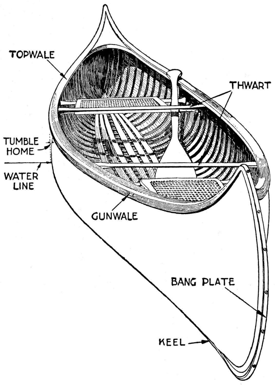
The Important Parts of a Canoe, Giving Names for the Information of the Novice
The particular shape, combined with the dimensions, of the canoe is commonly called the model, and since many canoe builders offer several different models it is a comparatively easy matter to find a craft which fully meets one’s ideas of a canoe. Canoes can be had as small as 10 ft. long and weighing as little as 18 lb., while others are built all the way up to 35 ft. and ranging around 50 in. wide. For all-around use, that is for cruising, hunting, and fishing, the 16-ft. length, with 32-in. beam, 12 in. deep amidships, and weighing about 60 lb., will meet the approval of the experienced canoeist. In a good canoe of this size a flat floor, medium-high ends, and a fair amount of tumble home—to add stability and keep the water from shooting inboard—may be reckoned the “earmarks” of a general-purpose craft. For exclusive river work, where many rapids are encountered, a lightly rounded bottom, a trifle lower in the center than at the ends, will be easier to handle in white water, while comparatively narrow ends will give more speed under the paddle.
All canvas-covered canoes are provided with brass bang plates, or irons, at stern and bow, and if wanted, an outside keel may be furnished. In most cases this is not essential, but when the canoe is largely used in rocky rivers a broad keel of ¹⁄₂-in. oak, or ash, 2¹⁄₂ in. wide in the center and tapered at both ends to fit the brass bang irons, will protect the bottom from hard knocks. The narrow 1-in. keel is an out-and-out nuisance, making the canoe slow to turn and furnishing but scant protection for the bottom. Any keel adds to the weight of the craft, and weight is a factor that must be considered when much portaging is done. So far as capacity is concerned, a canoe, 16 ft. long, 32-in. beam, and 12-in. amidship depth, will accommodate two men and the usual amount of camp duffle, weighing from 350 to 400 lb. On short trips, a 15-ft. canoe may be made to accommodate two men, while on very long cruises, where a larger amount of duffle must be taken along, an 18-ft. canoe may be needed. For three persons, the 17 or 18-ft. canoe, of 34-in. beam, is about right, but for a party of four it is better to use two 16-ft. canoes than one large craft. In fact, canoes longer than 18 ft. are more properly regarded as freight craft and only used on special trips.
Moccasins, or rubber-soled footwear, are most suitable for the canoeist’s wear, but since heavy-heeled shoes are often worn, it is a good plan to protect the thin planking by running a slatted floor, 8 or 10 in. wide, in the center of the canoe. Provide this grating with brass buttons, and it will be held firmly in place, but removable at any time. For convenience in towing, a small but flexible rope—braided cotton is always soft and pliable—about 20 ft. long, should be tied at both bow and stern. The ordinary “painter eye,” which fastens with a bolt screwed to the under[99] side of the breast hooks, is good, but a small hole, through which the rope is securely knotted, will serve as well.
The best material for paddles is good selected spruce, and while this material is not so heavy nor will stand hard knocks so well as maple or birch, its lightness makes it the choice of many paddlers. For rough work the maple paddle may be chosen, and while heavier than spruce, it possesses greater elasticity, and this spring offsets to a great extent the larger weight of material. Cedar, ash, and pine make excellent paddles, and the Indians often fashion them from these woods.
In selecting a single-blade paddle, it is well to remember that the length will depend on the paddler’s height, for it is self-evident that a tall man will require a longer paddle than a short person can conveniently swing. Hence the usual rule is to pick out a paddle as long as the paddler is tall, and is a sensible one to follow, although there are exceptions. Personal preferences differ, and, also, a longer paddle will be required when paddling from seats than when a kneeling position is adopted. For general use, the stern paddle of 5¹⁄₂-ft. length will be long enough, while the bow paddle of 5 ft. will probably suit the average man. Ladies, boys, and girls will need shorter lengths.
The shape of the paddle blades varies somewhat, and while some prefer a broad blade and others a narrow one, it is well to pick out one of medium size. Large blades are tiresome for long trips, while the narrow blade balances best in the hand, but affords less resistance in the water. When picking out a spruce paddle, see that there is plenty of wood at the juncture of the blade and shaft, for it is at this point most paddles break. Spruce being a comparatively soft wood, it will fur badly, and the blades should be fitted with copper tips to prevent splitting. Maple paddles do not need this protection, but most builders err in making them too thick and heavy. Pick out the lightest and thinnest maple paddle that can be found, one that is fashioned of straight-grained wood, and test it for elasticity before making the purchase. A couple of coats of spar varnish will keep the paddles in good shape, but as a varnished surface is hard on the hands, most veteran canoeists varnish the blades and finish the shafts with oil. An extra paddle will, of course, be carried on all long trips.
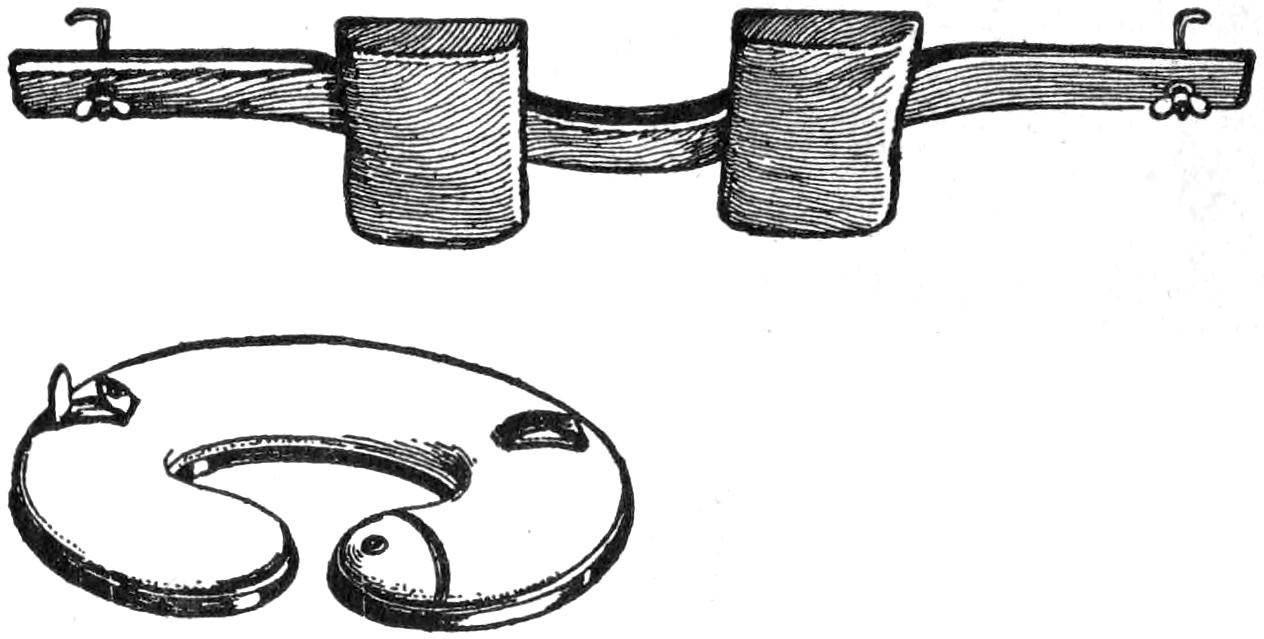
Canoe Yoke Equipped with Adjustable Shoulder Pads, and the Pneumatic Carrier That Serves Two Purposes
The single-blade paddle is quite universally used, but the double-blade gives more spread for the lone paddler. Although the double-blade was designed for the “Rob Roy” type of canoe—a one-man craft, decked both fore and aft, the paddler sitting in a cockpit in the center—it is sometimes used for propelling the open Canadian canoe, and when the canoeist travels alone, the double-blade is a good choice, especially on open waters where much wind and high seas are likely to be encountered. Spruce is the best material for double paddles, and 10 ft. is the best length. As all double-bladed paddles are provided with a ferrule, or friction joint, in the center, they may be unjointed and each used as a pair of single paddles. In case the open end of the metal ferrule is objectionable, a wood plug may be fitted to provide a palm grip, similar to the grip of the single paddle.
When the weight of the canoe does not exceed 65 lb., it is easily carried by placing the paddle blades over the center thwart, the ends under the next after thwart and lashing them securely in place; then placing a sweater or coat over the shoulder to form a[100] pad on which to rest the paddles to carry the canoe in an inverted position. However, when long portages must be undertaken the “neck yoke,” or the pneumatic canoe yoke, may be used. The neck yoke is fashioned from a block of pine, or other soft wood, to fit the curve of the shoulders, and the ends fit in the grooves made in the gunwales; or small pieces of wood may be screwed to the under side of the gunwale to serve the same purpose. The pneumatic cushion, which fits around the neck and is provided with straps to secure the paddles in position, is well-liked by some canoeists, but the wood neck yoke fits so well that it is hard to find a good substitute. A large and heavy craft can be easily carried by two men by turning the craft bottom side up and resting the weight on the back and shoulders. If the man at the stern lets the gunwale rest on his shoulders and his companion lower the front thwart to rest against his neck and shoulders, both may carry a light pack of duffle and will have a clear view of the trail ahead.
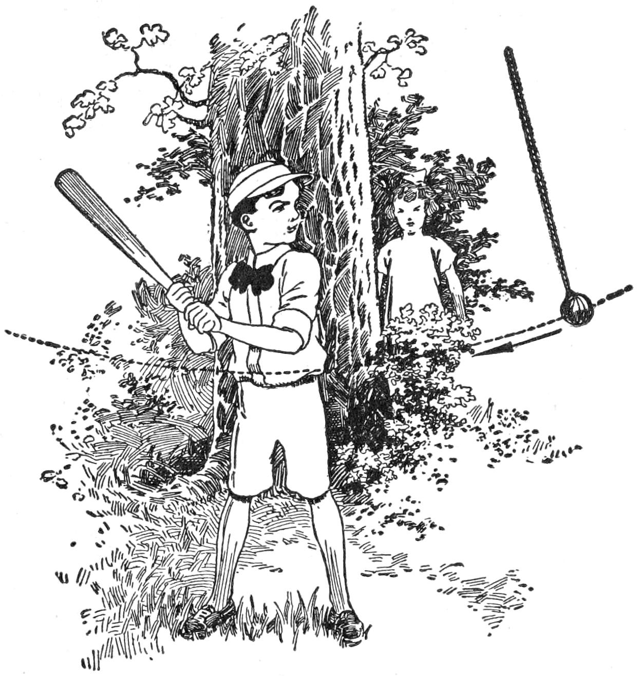
Learning to Strike a Ball without the Aid of a Pitcher or Fielder
A boy with a very great desire to make a good ball player found that he could not hit a ball tossed to him. Try as he might, the bat never hit the ball. Some one suggested that a ball hung by a cord would help to a great extent, and it was tried out with excellent results. An inexpensive ball was suspended from the limb of a tree so that it would be at the proper height for the batter. In striking at the ball it was not necessary to make home-run hits, as this is liable to break the cord, or get it tangled to its support. If the strikes are made properly, the ball will swing out and come back in a perfect curve, or can be made to come back bounding and in no straight line. This will teach the eye to locate the ball and make hits where it cannot be taught by having some one toss the ball to the striker.
A very true and artistic impression of a leaf, or similar object, can be made as follows: Grease a piece of heavy writing paper with linseed oil, and smoke the surface well by lighting a small piece of camphor gum and holding the paper over the flame. Place the leaf on the smoked surface of the paper and cover it with several thicknesses of newspaper, then press the leaf into the blackened surface. Remove the leaf and lay it with the blackened surface on a piece of white paper, then cover again with the newspaper and press evenly and thoroughly. A beautiful and permanent impression of the leaf will be transferred to the paper.
Care should be taken not to move the leaf the least bit either in coating it with the smoke or in transferring it to the paper. Be careful not to use too much oil. This process can be used to stamp cloth for embroidery. A candle can be used in place of the camphor if care is exercised, but the camphor gives a very dense smoke with a minimum of heat.—Contributed by J. H. Beebee, Rochester, N. Y.
[101]

The making of a single article of any kind presents a distinct problem in itself, but the production of a large number of the same article must be done in a different way, if efficiency and uniformity in the product are desirable qualities. Taking, for instance, the making of a large number of T-squares, the material is not made up in the same manner as for one. Where a number of these instruments was required, they were made as follows, with no other Equipment than bench tools and a band saw. The squares were made of mahogany having both stock and blade edged with maple. The blades were fastened to the stock with five ³⁄₈-in. button-head screws.
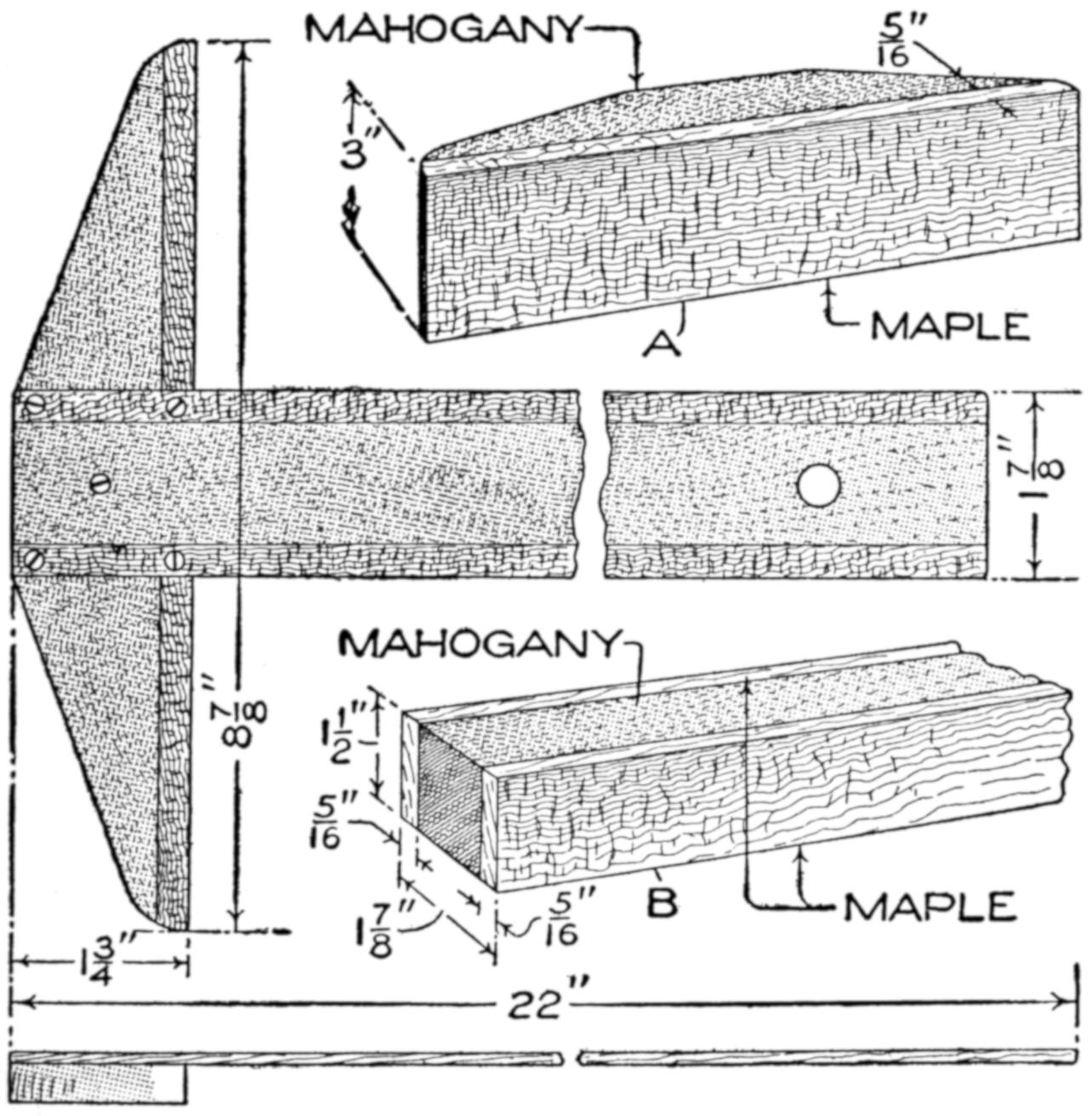
Dimensions for a T-Square of Which a Number where to be Made in Duplicate
The material for the heads and the blades was glued up and finished to the sizes given at A and B. The material was cut to gauge lines on the band saw, the blades being a scant ¹⁄₈ in. in thickness, and the stocks, ³⁄₈ in. Two of each were cut from each prepared piece, first from one side and then from the other. They were then faced off on both sides, and two more pieces cut. With careful cutting, six blades and six stocks were made from each piece. This left one side of each piece to be planed after sawing. The holes for the screws were drilled with a small hand drill.
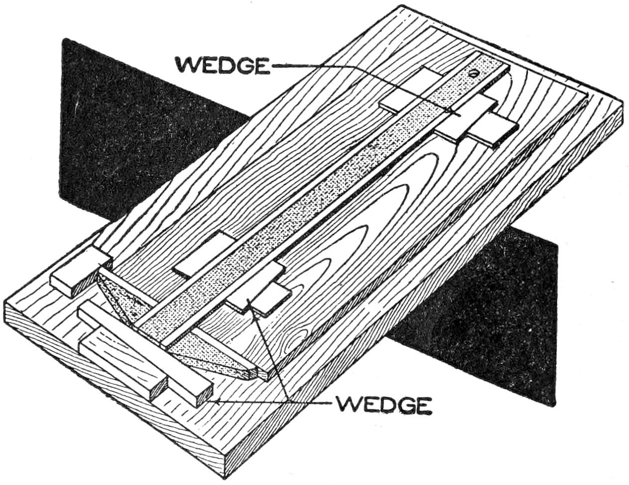
Stock and Blade Material for Making the Parts, and the Jig for Assembling
For assembling, a jig was made by nailing a piece of stock, ³⁄₈ in. thick, to a straight drawing board. One end of the piece was planed straight and true before it was fastened in place. Stops were provided to locate the stock and hold the blade square with it. Wedges were used to keep both stock and blade against the stops while the screws were inserted. The wedges were not driven with a hammer, but pushed in firmly with the fingers.
¶Insert a scratch awl in common hard soap for hardening, and it will need no drawing after the plunge.
[102]
Paddling Your Own Canoe
by
Stillman Taylor
PART II—The Knack of
Handling the Paddle
The knack of paddling a canoe as the majority of amateurs paddle is quickly learned, but to handle a paddle as the expert woodsman and the Indian wield it requires not a little practice and experience. In the birch-bark and canvas-covered craft, used by the guides of Maine and Canada, there are no seats, and the stern paddler kneels with his back against the rear thwart, while the bow paddler usually kneels with his back against the second thwart from the bow. However, the builders of modern canoes furnish a seat for each paddler, and while it is more comfortable to use them, it is better to take the kneeling position, which brings the weight lower in the canoe, as it is safer, and the paddler is better able to control his craft. Again, the use of the seat makes it impossible for the paddler to put much of his body into the stroke, and he propels the craft largely through the muscles of his arms and shoulders. But when paddling from the knees they are spread out to brace the body firmly, and the back resting against the thwart enables the paddler to use his back and thigh muscles to drive his craft ahead with much less exertion and waste of energy than when sitting erect. Of course, the kneeling position is a source of discomfort at first, but after a little practice it will be easy to keep the position for several hours.
The stroke of the paddle is made with the body motionless, one hand grasping the shaft of the paddle and the other holding it a short distance above the blade. The paddle is now carried forward, dipped into the water in front, Fig. 1, A and B, and carried downward past the paddler’s body, Fig. 2, A and B, and the stroke is finished in the rear, Fig. 3, A and B. The paddle is recovered by turning the wrist so that the blade is turned edgewise as it is swung through the air to begin the second stroke. The swing of the paddle should be smooth from the beginning to the finish of the stroke, that is, free from undue jerkiness, but the long and slow sweep of the paddle is amateurish, pure and simple. The canoemen of the North woods do not use this stroke, but prefer a shorter stroke, quick recovery of the blade, and the “accent” of the stroke is much the same as that the expert axman uses when felling a tree. Therefore one’s energy should be concentrated upon the first part of the stroke, easing up quickly as soon as the blade is opposite the body, and finishing the stroke smartly as it is carried backward. The driving power of the paddle diminishes rapidly as the blade is carried backward, and if the full force of the stroke is continued with a long backward sweep, a way of most amateurs, much energy is wasted, since it adds nothing to the forward momentum[103] of the canoe, but rather retards it, by forcing down the stern, and also causes the craft to drag more water after it. For a short afternoon paddle almost any kind of a stroke will suffice to drive the canoe ahead, but upon long trips, or when head winds and rough water are encountered, the quick, short stroke will save both time and muscle. The long sweeping stroke of the summer idler will probably average about 26 to 30 strokes per minute, while the North-woods guide and Indian will dip their blades almost twice as often, a fair cruising average being about 45 strokes per minute. Short strokes, with the accent at the beginning of the stroke, will push the canoe faster and with less effort, and the paddler has better control over his craft.

Fig. 1-A
Fig. 2-A
Fig. 3-A

Fig. 1-B
Fig. 2-B
Fig. 3-B
The Stroke of the Paddle is Made with the Body Motionless, One Hand Grasping the Shaft of the Paddle and the Other Holding It a Short Distance above the Blade
The bow paddler usually does nothing more than keep up a regular stroke and watch for rocks and obstructions, but if he is a good hand at the paddle he can do much to steer the canoe. For example, take the usual bow stroke, made by dipping the paddle quite close and ahead of the canoe. The force of the stroke thus made forces the bow in the opposite direction, and the man in the stern will be called upon to use more energy in steering. In contrast to this faulty handling of the paddle, the experienced bowman will begin his stroke by dipping his paddle well out from the bow and pulling it toward him at a greater angle, which keeps the canoe moving straight ahead without swinging to one side, and the energy of both paddlers is used in driving the craft steadily ahead. When paddling in tortuous and rocky streams it is the bow paddler’s duty to watch out for rocks and snags, and he should always be prepared to “draw” the canoe whenever it is necessary to clear an obstruction or assist the stern paddler to shoot the canoe around an abrupt bend. To do this is simple enough, since the bowman merely reaches his paddle out at arm’s length over the side and pulls the bow in that direction, while the stern paddler simply paddles straight ahead.
The stern paddler is the helmsman of the canoe, and while he can keep his craft on a straight course by trailing his paddle at the end of each stroke and using it like a rudder, it can only be done when a long, slow stroke is used. To save time and muscle, the experienced stern paddler always finishes his stroke with an outward push and a turn of the wrist, which offsets the swing of the bow and keeps the canoe on a straight course with much less effort than when trailing the paddle astern. Paddling from the stern is often considered difficult, but one soon masters it by a little experience.
[104]
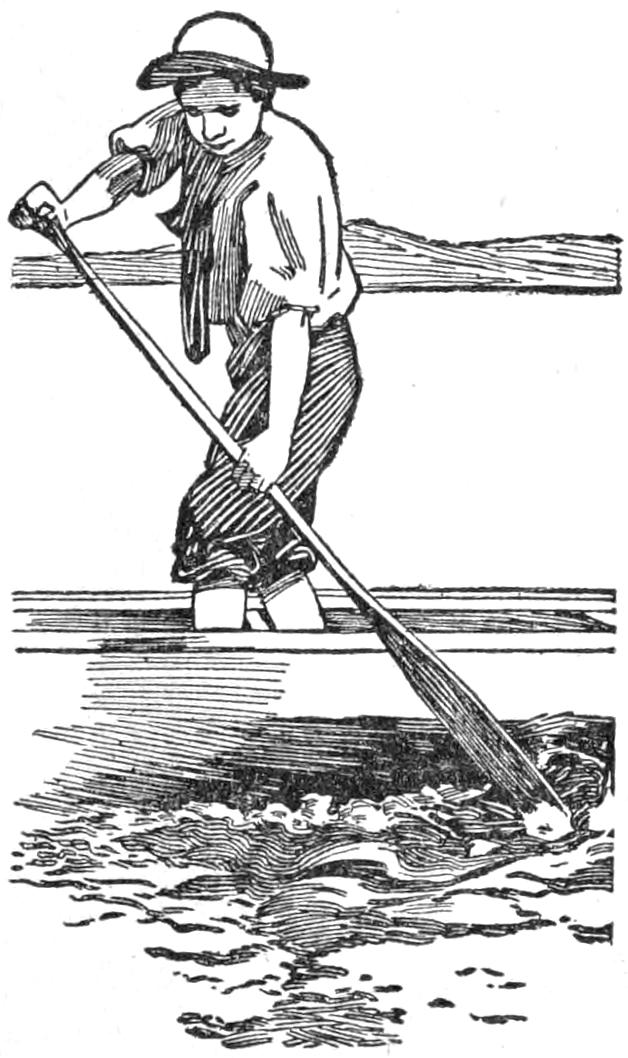
Dangerous for the Novice, but Experts Win Races in This Position
When traveling in the open waters of large lakes where heavy winds and seas are commonly encountered, paddling should always be done on the knees, and the canoeist’s own experience and judgment must be called upon to meet constantly changing conditions of the wind and water. To cross a broad stretch of wind-swept water where whitecaps are running high, means a long, hard fight, and the stern paddler must be ever alert to ease the canoe through breaking crests and shift his balance whenever the necessity arises. When paddling in rough water, many canoeists make the mistake of driving their craft too hard, consequently the canoe will “pound” when it reaches the trough of the sea, and much unnecessary spray is sent flying aboard. Of course, in rough water some spray is certain to come over the rail, but if the craft is well balanced by stowing the camp duffle so that the canoe floats on an even keel, it will, with proper handling, weather a pretty stiff gale.
When paddling against a heavy sea and wind, the regular stroke must be altered and modified, and the man in the stern may often balance his craft by holding his paddle in the water while a particular high comber sweeps by. Short and clean strokes are essential for handling the canoe in a heavy sea, and while the skillful canoeist can handle his craft in the trough of the sea when the need arises, it is hazardous for the novice to attempt it. In heavy weather, it is a good thing to keep one paddle in the water while the other is in the air, hence the experienced canoeist will—unconsciously perhaps—alternate or “split” strokes with his bowman.
To paddle, head on, into heavy seas is slow and tiresome work, and most canoeists find it easier to take the seas on the quarter, and the stern paddler must be ever on the lookout, nursing his craft over the big ones and often turning his bow into the largest combers. To be sure, the canoe will plunge more or less and yaw about, but the stern paddler merely checks this side spin, since he cannot prevent it entirely and drive his craft onward at the same time. When running before the wind, it is only necessary to keep the canoe balanced or “trimmed” to keep things dry. Here the bow paddler has the best of it; his sole duty is to keep paddling steadily ahead, while the balancing and handling of the canoe rests with the man in the stern. This point is well worth remembering, for to keep the canoe right side up when shooting rapids or when bucking heavy seas or a lake, the bow paddler must stick to his seat. He can, from his position in the bow, quickly note rocks or other obstructions and pass the word to his partner, who from his point of advantage can likewise better size up the effect of a high wave upon the craft. Probably more capsizes have resulted through the bowman’s mistaken efforts to balance the canoe by leaning to one side, or attempting to dodge the spray in rough-water paddling, than through the inability of the stern paddler to handle his craft.
Running a rapid stream in a canoe is replete with excitement, but it is likewise a dangerous bit of fun for the inexperienced canoeist who has not fully mastered the handling of his craft. When running rapids where the water is fairly deep, the use of the paddle is the better way, providing both paddlers kneel in the bottom of the canoe. Unknown streams are naturally the most dangerous, although the veteran canoeist can “size” up the character of the stream at the first glance, that is, the trained eye of the woodsman will read the bottom of the river by the indications on the surface; depth of water, strength of current, swirl caused by submerged rocks, and many other details[105] are evident to him. To the novice these signs mean but little. If the current flow is from three to four miles per hour, rocks or submerged logs, 4 or 5 in. below the surface, will show very little, but in a 10-mile or swifter current obstructions 12 or even 18 in. below the surface will throw up swirling ripples, and in a very rocky stream with much water flowing, rocks 3 or 4 ft. below will throw up waves of good size. Again, waves are caused by swift water striking the comparatively quiet water of a deep pool and the canoeist should be able to determine the difference between them in order to know what part of the stretch is dangerous and that which may be run in safety.
The waves in a rapid stream are altogether unlike the rolling waves of the open lake, in that the crests follow one another closely and the canoe cannot rise, but plunges through the curling crests. Rocks on the surface are easily avoided, as they split the current, and it is only necessary to steer the craft to one side to pass them safely. The one chief thing to do when shooting the rapids is to keep the canoe on an even keel and the bow into the current, and when it is necessary to change channels, the craft must be shot diagonally across the fast water. To keep the canoe under perfect control in white water, it must be propelled faster than the current flows, and the force of the stream must not strike one side of the bow with greater force than it exerts on the other side. When a canoe swings around in the current, the power of the paddles will be unable to cope with the more powerful current, which quickly swings it broadside and one is struggling in the water in the next instant.
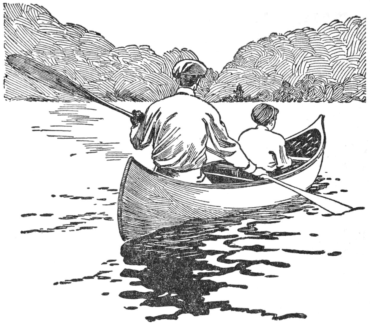
The Double Blade Is Often Useful When Paddling Single-Handed on a Broad Reach of Wind-Swept Water
On a long canoe trip where much rapid water must be run, a “setting pole” should be reckoned a necessity. The pole may be a stout sapling, 10 ft. long, cut by the stream side, but an iron shoe, or spike, about 3 in. long, with an iron band or ferrule, should be carried in the kit, the iron spike being simply driven in the end of the green pole. The pole may be used to good advantage when running down shallow rapids, the man in the bow kneeling and using his paddle to help steer while his partner stands in the stern and wields the pole. When traveling up shallow and swift streams, the setting pole is absolutely necessary, and while at first it is an awkward implement to handle, a little practice will enable the canoeist to pole his craft with very little more effort than is required to paddle it. The use of the pole necessitates a standing position, but this is neither risky nor difficult for any canoeist who understands the knack of balancing a canoe, and none but an experienced canoeist has any business in swift, white water. The setting pole is gripped with the left hand near the top, with the right hand held stationary about 2 ft. lower, and as the canoe travels past the pole, firmly planted on the river bottom, the poler leans forward and makes use of his weight and strength to give a quick push. The pole is again shoved forward as quickly as possible, that the craft may lose as little headway as possible, and a new grip secured for the next push. After a little experience with the pole, the canoeist will find it an easy matter to swing his craft across the current and avoid rocks and other obstructions as easily as when paddling. When contemplating a long trip up a stream where the water is heavy and the current swift, the use of two poles will make the work easier. Both persons should pole from the[106] same side, the man in the bow doing the steering while the stern man adds his straight-ahead push to force the canoe upstream.
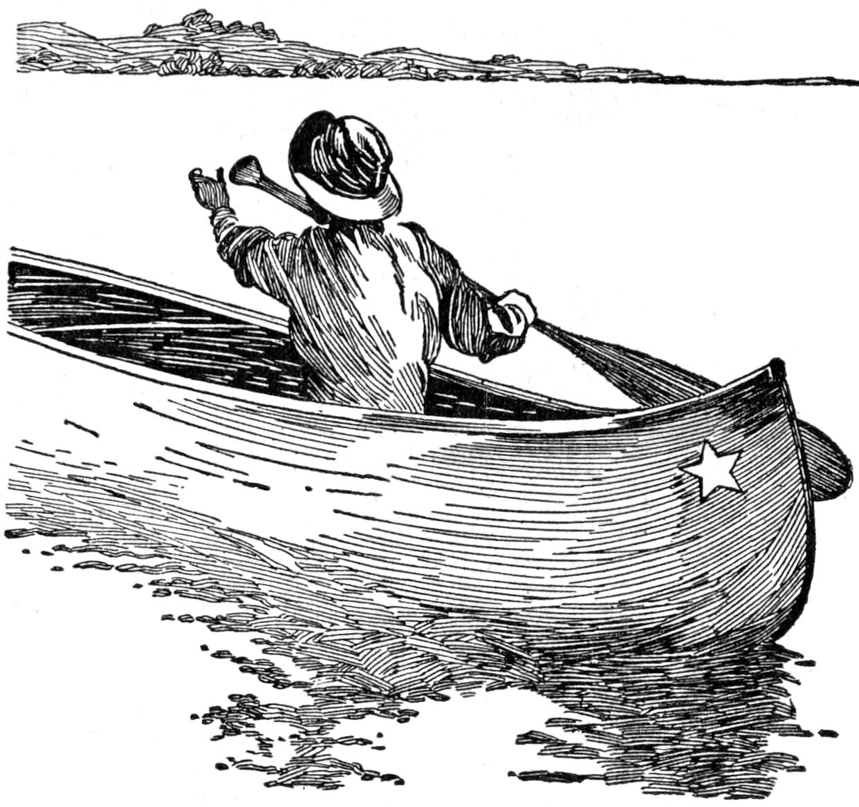
Shifting the Paddle from One Side of the Canoe to The Other
The average wilderness stream of the North has enough “tight” places which judgment tells the traveler to avoid by making a detour by land rather than risk a capsize and a possible loss of the outfit. To “tote” the outfit overland means more or less hard work, and as every canoeist will avoid portaging if there is a fair chance of getting the canoe through a bad stretch of water, the tracking line will come in handy very often. The usual ring in the bow of the canoe is far too flimsy for hauling the loaded craft, and sufficient length of stout rope should be carried along to pass through the painter eye, and then carried aft and half-hitched to the first and second thwarts. One man can pull the canoe up a swift stream by walking along the bank while his partner takes up the opposite side and steers the craft away from rocks by using a stern line. With a heavily loaded canoe in very swift and shallow water, both men must often wade, and a tump line rigged up as a breast or shoulder strap will make it easier work for the man at the bow line.
The open, or Canadian-model, canoe is, of course, handled more easily and with better speed with two paddlers but there are occasions when the canoe is used single-handed. When out for a few hours’ paddle, the canoeist usually balances the craft by sitting on the bow seat—or kneels on the bottom with his back against the bow-seat brace—and using the stern for the bow. This brings the paddler’s weight nearer the center and keeps the canoe better balanced than when paddling from the stern with the bow high in the air. However, when the canoe is loaded, many canoeists stow their camp duffle forward and paddle from the stern, the weight of the outfit keeping the craft on an even keel. This answers well enough for smooth-water going, but when the water is rough, or a stretch of rapids is run single-handed, the stern position is by no means a good one since the craft is more difficult to control, and much more strength is required to drive it forward. The Indian manner of paddling a canoe alone is the only correct one, for he always sits amidships—kneeling in the center—and if a load is carried, it is placed in front and back of him so that the craft is balanced on an even keel. Consequently the canoe draws less water and can be paddled faster with the same effort, while the paddler has the craft under perfect control. But the experienced line paddler does not kneel in the center, he moves out until his body is close to the gunwale. This makes the craft heel at a decided angle, it is true, but this position makes for better speed because it enables the paddle to be held almost vertical, and the more nearly perpendicular the paddle is swung the more efficient will be the stroke.
In using the double blade, the paddler dips first on one side, then on the other, and to make the blades travel through the air with the least resistance, it is customary to set them at right angles to each other. The motion is really a push and pull, the shaft of the paddle being rotated in the hands so that the blade will enter the water with the full breadth facing the canoeist. Rubber cups, to catch the drip as the paddle rises in the air when making[107] the stroke, are sometimes used by novices, but these are unnecessary if the paddles are set at right angles, and the paddler will bend his wrist a trifle to throw the drip ahead and to one side. At the beginning, the novice will very likely throw a little water in the canoe, but a little practice will soon master the knack.
The canvas-covered cedar canoe will stand a vast amount of hard service, but it should not be dragged over the ground or over the boarding of the landing float, neither should it be so placed that any strain will come amidships while the ends are well supported. When storing for the winter, keep it under cover, resting bottom side down on a floor, or turn it bottom side up and support it with boxes, or other standards, at the center as well as at the ends. While unused at the camp, turn it bottom side up on the bank. Birch bark must be kept out of the sun, and the paint of canvas-covered canoes will last longer if kept in the shade. When the paint becomes rough, sandpaper it down smooth, and give it a couple of coats of canoe paint. When the paint is worn off and exposes the canvas, give the bare cloth a couple of coats of shellac before painting.
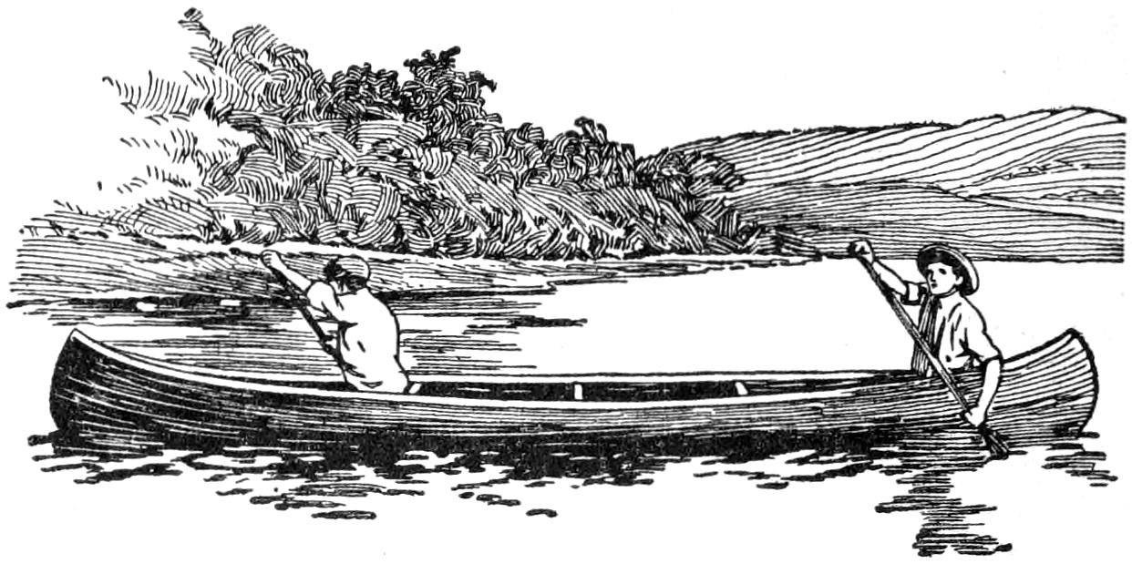
Paddling should be Done on the Knees When Traveling Where High Winds and Seas are Encountered
A repair kit should be taken along on all long trips, consisting of a small can of white lead, a can of orange shellac, and a sheet of oiled silk. For small cuts in the canvas, a coat or two of shellac will suffice, but for bad gashes, cut off the loose threads of canvas and rub on a little white lead under the raised portion near the hole and on the surface, cut a patch of the oiled silk to cover it, and paste it in position. When the lead is dry, give it a couple of coats of shellac. For making quick repairs, a roll of electrician’s tape will come in handy. The birch canoe is quickly repaired in the same manner as suggested for the canvas-covered craft, and as the shellac is waterproof and dries quickly, all ordinary repairs may be made by the stream side with but little loss of time.
Jewelers use a little tool for oiling clocks and watches that could be used profitably by others for the same and similar work. It consists of a steel wire, bluntly pointed on the end and set into a wood handle. Very often the only thing that is the matter with a clock which does not keep good time, is that it is dirty and dry. If this is the case, any person handy with tools can fix it at practically no cost. Remove the works, which are usually held with four screws, from the case, immerse them in kerosene and allow them to stand for a few minutes, then remove and drain. This will clean out the dirt.

The Tool will Pick Up a Drop of Oil and Deposit It Where Wanted
The oiling tool is dipped in light oil and a drop applied to each bearing. Replace the works in the case and the job is finished. A reliable jeweler will charge very little for this work, but the more crafty ones may ask a good price for this “mysterious” process. If the works are not dirty, apply the oil with the tool. Anyone who has tried to oil a clock with an ordinary spout oilcan knows the futility of the attempt. The object of the tool is to pick up and carry a drop of oil and deposit it where wanted. A can, a feather, or a match will do, but any one of them is apt to carry dirt, flood the dry part, or smear up nonmoving parts.
[108]
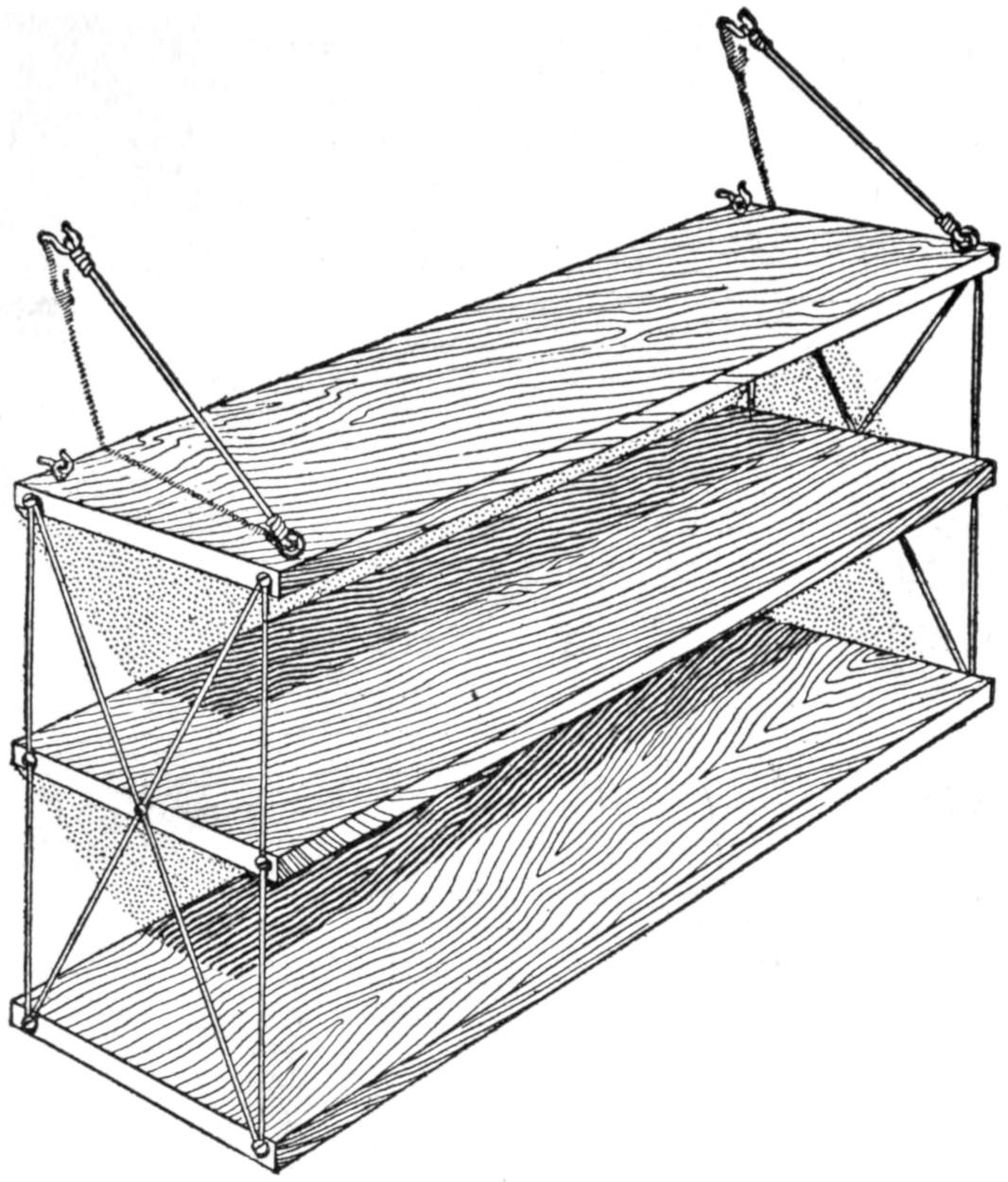
Shelves for Books Supported with Picture-Frame Wire to the Wall
All that is necessary to make and support the simple set of wall shelves, shown in the illustration, is lumber for the shelves, four screw eyes, four screw hooks, sufficient picture-frame wire to form the braces and supports, and wood screws for attaching the wire. On the top side of the upper shelf are fastened the four screw eyes, two near the wall edge and the others near the outer edge. To support the upper shelf four screw hooks are used; two placed in the wall and spaced to match the set of screw eyes nearest the wall, the others being placed above the first and connected to the outer set of screw eyes with the wire, thereby forming strong inclined supports. The remaining shelves can be hung to suit by the supporting wires, which are fastened with screws to the end of each shelf.
This trick is not so well known as it might be, although for a while it was quite a popular drawing attraction for circus side shows and other amusement places. It is one of the favorite Hindu tricks. The performer passes for examination two pieces of rope 10 ft. long. In one end of each rope a large ring is fastened. Taking a ring in each hand the performer commands three or four men at each end of the rope to take hold of it and at a signal they pull as hard as possible. They pull until they are exhausted as in a tug of war, but the performer only appears a trifle exerted and finds no difficulty in holding the men.
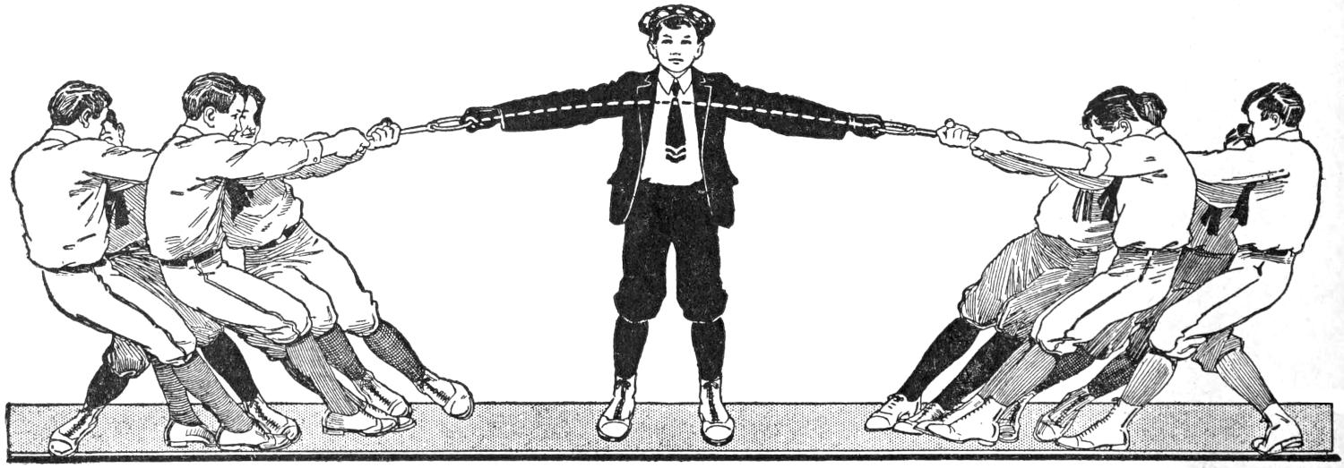
The Performer Seems to Hold the Ones Pulling on the Ropes without Any Effort, Producing an Effect That cannot be Readily Understood, and Making an Excellent Trick for the Lawn Party
The secret is in the use of a piece of flexible wire, which passes up the right sleeve of the performer, across the back and down the left sleeve, lying just inside of the coat sleeve. At the ends of the wire are small hooks. When about to perform this trick the performer puts on a pair of gloves. The gloves are slit in the palms to allow the hooks to pass through. The hooks are covered with cloth, colored to match the gloves. An essential point to remember in performing the trick is to keep the fingers well around the rings to prevent the ropes from dropping in case of a slack-up on the tension.
[109]
To enjoy a vacation in the woods thoroughly, it is essential that the outer be provided with the right kind of an outfit. The inexperienced are likely to carry too much rather than too little to the woods; to include many unnecessary luxuries and overlook the more practical necessities. However, camp life does not mean that one must be uncomfortable, but rather implies plain and simple living close to nature. An adequate shelter from the sun and rain, a comfortable bed, a good cooking kit, and plenty of wholesome food, are the important things to consider. No man or woman requires more, and if unwilling to share the plain fare of the woodsman, the pampered ones should be left at home, for the grouchy, complaining individual makes, of all persons, the very worst of camping companions.
The Old Hand at the Camping Game Prefers to Cut Poles on the Camping Site and Set Them Up on the Outside for the Camp-Fire Tent
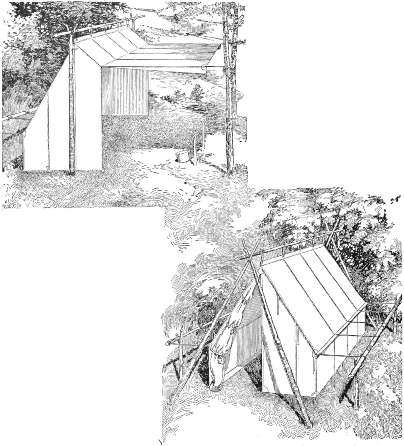
The Wall Tent may be erected with the Regular Poles, or, When Ordered with Tapes along the Ridge, It can be Set Up with Outside Tripod or Shear Poles
There are tents and tents, but for average outings in what may be considered a permanent camp, the regulation wall, or army, tent is generally used to make a comfortable shelter. It is a splendid utility tent, with generous floor space and plenty of headroom. For the permanent camp, the wall tent is often provided with a fly, which may be set up as an extra covering for the roof, or extended over the front to make a kind of porch. An extension may also be purchased to serve the same purpose. The 7 by 9-ft. wall tent will shelter two persons comfortably, but when the camp is seldom moved, the 9 by 12-ft. size, with a 3¹⁄₂-ft. wall, will afford more room. The regulation[110] 8-oz. duck is heavy enough, or the same tent may be obtained in tan or dark green khaki, if preferred. In any case the tent should have a sod cloth, from 6 to 12 in. wide, extending around the bottom and sewed to the tent. An extra piece of canvas or floor cloth is desirable, but this as well as the fly are extras, and while convenient, are by no means necessary. The wall tent may be erected with the regular poles, or it may be ordered with tapes along the ridge and erected by suspending between two trees. The old hand at the camping game rarely uses the shop poles supplied with most tents, but prefers to cut them at the camping site and rig them up on the outside, one slender pole fastened with tapes along the ridge and supported at either end in the crotch formed by setting up two poles, tripod or shear-fashion.
The “Baker” style is a popular tent, giving a large sleeping capacity, yet folding compactly. The 7 by 7-ft. size, with a 2-ft. wall, makes a good comfortable home for two, and will shelter three, or even four, if required. The entire front may be opened to the fire by extending it to form an awning, or it may be thrown back over the ridge to form an open-front lean-to shelter.
The “Dan Beard,” or camp-fire, tent is a modification of the Baker style, having a slightly steeper pitch, with a smaller front opening. The dimensions are practically the same as the Baker, and it may be pitched by suspending between two trees, by outside poles, or the regular poles may be used.
For traveling light by canoe or pack, a somewhat lighter and less bulky form of tent than the above styles may be chosen, and the woodsman is likely to select the forester’s or ranger types. The ranger is a half tent with a 2-ft. wall and the entire front is open; in fact, this is the same as the Baker tent without the flap. If desired, two half ranger tents with tapes may be purchased and fastened together to form an A, or wedge, tent. This makes a good tent for two on a hike, as each man carries his own half, and is assured a good shelter in case one becomes separated from his companion, and a tight shelter when the two make camp together.
The forester’s tent is another good one, giving good floor space and folding up very compactly, a 9 by 9-ft. tent weighing about 5¹⁄₂ lb. when made of standard-weight fabric. It may be had either with or without hood, and is quickly erected by using three small saplings, one along the ridge, running from peak to ground, and one on each side of the opening, to form a crotch to support the ridge pole, shear-fashion. These tents are not provided with sod or floor cloths, although these may be ordered as extras if wanted.
The canoe or “protean” tents are good styles for the camper who travels light and is often on the move. The canoe tent has a circular front, while the protean style is made with a square front, and the wall is attached to the back and along the two sides. Both tents are quickly set up, either with a single inside pole or with two poles set shear-fashion on the outside. A 9 by 9-ft. canoe or protean tent with a 3-ft. wall makes a comfortable home in the open.
Whatever style of tent is chosen, it is well to pay a fair price and obtain a good quality of material and workmanship. The cheaper tents are made of heavier material to render them waterproof, while the better grades are fashioned from light-weight fabric of close weave and treated with a waterproofing process. Many of the cheaper tents will give fair service, but the workmanship is often poor, the grommets are apt to pull out, and the seams rip after a little hard use. All tents should be waterproofed, and each provided with a bag in which to pack it. An ordinary tent may be waterproofed in the following manner: Dissolve ¹⁄₂ lb. of ordinary powdered alum in 4 gal. of hot rain water, and in a separate bucket dissolve ¹⁄₂ lb. of acetate of lead—sugar of lead—in 4 gal. of hot rain water. The acetate of lead is poisonous if taken internally. When thoroughly dissolved, let the solution[111] stand until clear, then pour the alum solution into a tub and add the lead solution. Let the solution stand for an hour or two, then pour off the clear water and thoroughly soak the fabric in the waterproofing mixture by rubbing and working the material with the hands. Hang the cloth up without wringing it out.
The Forester’s Tent is Quickly Erected by Using Three Small Saplings, One along the Ridge, and One on Each Side of the Opening to Form a Crotch for the Ridge Pole
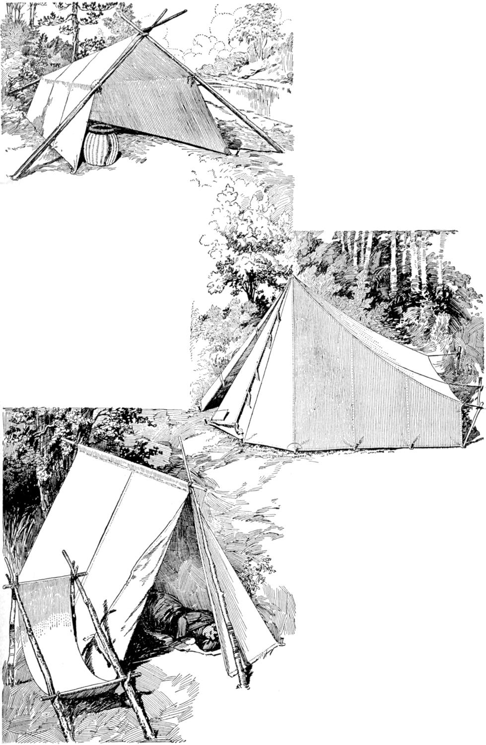
The Ranger’s or Hiker’s Tent Comes in Halves. Each Half may be Used Independently as a Lean-To Shelter for One Man, or Both Joined Together to Make Room for Two Persons
The Canoe or Protean Tents Are Good Styles for the Camper Who Travels Light and Is Often on the Move, and They can be Quickly Set Up with a Single Inside Pole
It is, of course, possible to pitch a tent almost anywhere, but for the sake of comfort, it is well to select a site with natural drainage. Many campers dig a shallow trench around the tent to prevent water from running in during a heavy rain. This is a good idea for the permanent camp, but is not often necessary if the soil is sandy or porous, or where a sod cloth is used.
It is rarely necessary to carry the regular poles to the camping ground, and they may be omitted excepting when en route to a treeless region. The wall and other large tents may be pitched in several ways. In some places the woodsman cuts a straight ridge pole, about 3 ft. longer than the tent, and two crotched uprights, 1 ft. or more longer than the height of the tent. The ridge pole is passed through the opening in the peak of the tent, or fastened to the outside of the ridge with tapes sewed to the[112] cloth. The two upright stakes are then firmly planted in the ground, one at the back and the other in front, and the ridge pole is lifted and dropped into these crotched supports. Set up the four corner guys first to get the tent in shape, then peg down the side guys and slide them taut so that all of them will exert an even pull on the tent. Another good method for setting up the side guys is to drive four crotched stakes, each about 4 ft. long, somewhere near 3 ft. from each corner of the tent, and drop a fairly heavy pole in the rest so formed, then fasten the guy ropes to this pole. When a sod cloth is provided it is turned under on the inside, the floor cloth is spread over it and the camp duffel distributed along the walls of the tent, to hold it down and prevent insects and rain from entering.
To overcome the disadvantage of placing the poles in the center of the entrance, the uprights may be formed by lashing two poles together near the top to make a crotch and spreading the bottoms to form a pair of shears. Poles may be dispensed with entirely, providing the tent is ordered with tapes for attaching a rope to suspend the ridge of the tent between two trees. In a wooded country this manner of setting a tent is generally preferred.
Where a wall tent is used in a more permanent camp, it is a good plan to order a fly, a couple of sizes larger than the tent. This should be set up by using separate poles and rigged some 6 or 8 in. higher than the ridge of the tent, thus affording an air space to temper the heat of the sun and also serving to keep things dry during long, heavy rains.
The camping kit, including the few handy articles needed in the woods, as well as the bedding and cooking outfit, may be either elaborate or simple, according to the personal experience and ideas of the camper. In making up a list, it is a good plan to remember that only comparatively few articles are really essential for a comfortable vacation in the wilderness. A comfortable bed must be reckoned one of the chief essentials, and one may choose the de-luxe couch—the air mattress or sleeping pocket—use the ordinary sleeping bag, or court slumber on one of the several other styles of camp beds. The fold-over combination bed, the stretcher bed, or a common bag made of ticking, 6¹⁄₂ ft. long by 2 ft. wide, which is stuffed with browse or leaves, will suffice for the average person. Folding camp cots, chairs, tables, and other so-called camp furniture, have their places in the large, fixed camps, but the woodsman can manage to live comfortably without them. A good pair of warm blankets should be included for each person, providing the sleeping bag is not taken along. The regulation army blankets are a good choice and reasonable in price, or the blankets used at home may be pressed into service.
A good ax is the woodsman’s everyday companion, and a good-weight tool, weighing 3 or 4 lb., and a smaller one of 1¹⁄₂ lb. should be carried. When going light, the belt ax will suffice.
The oil lantern is only suited for the fixed camp, since the fuel is difficult to transport unless it is placed in screw-top cans. The “Stonbridge” and other folding candle lanterns are the most convenient for the woods and give sufficient light for camp life.
The aluminum cooking outfits are light in weight, nest compactly, and will stand many years of hard usage, but like other good things, they are somewhat expensive. A good substitute, at half the price, may be obtained in tin and steel, having the good feature of nesting within each other, but, of course, not being quite so light nor so attractive in appearance as the higher-priced outfits. Both the aluminum and steel outfits are put up in canvas carrying bags, and an outfit for two includes a large and a small cooking pot coffee pot; frying pan with folding or detachable handle; two plates; cups knives; forks, and spoons. Outfits may be bought for any number of persons and almost all sporting-goods stores carry them. The two-man outfit in heavy aluminum will cost $9 or $10, while the same outfit duplicated in steel is priced at $3.35.
[113]
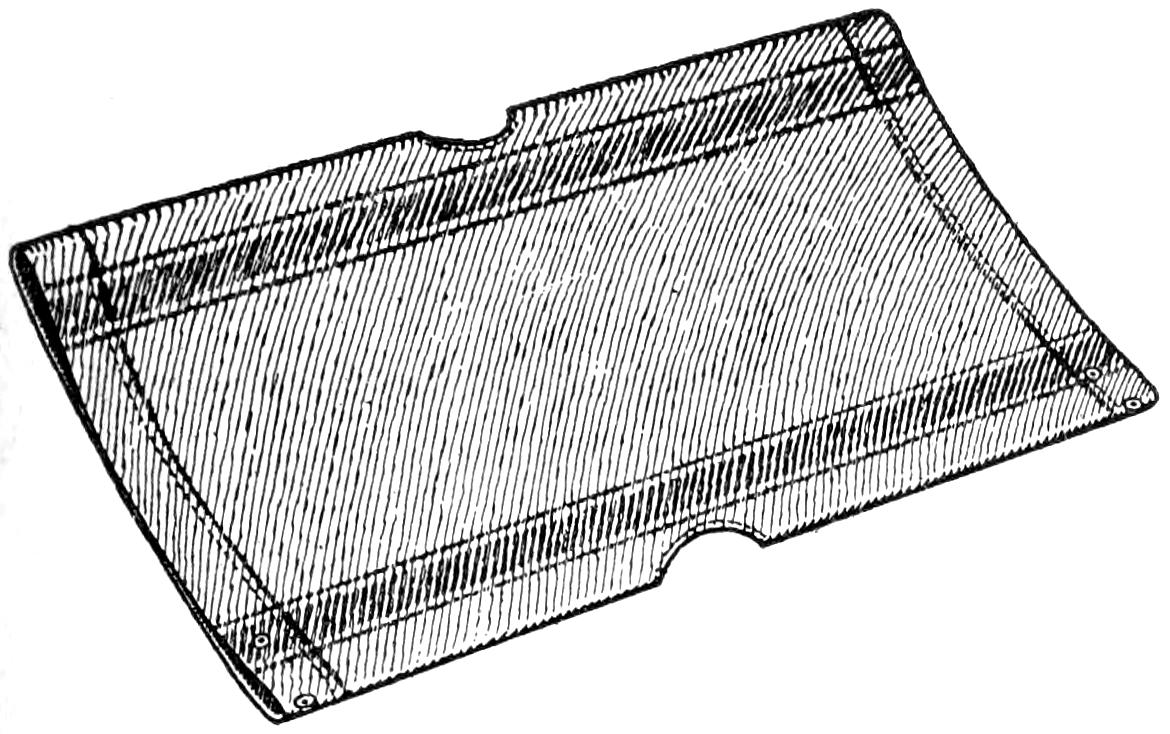
The Stretcher Bed may be Stuffed with Browse or Leaves, or Suspended from Poles and Stakes to Make a Camp Cot
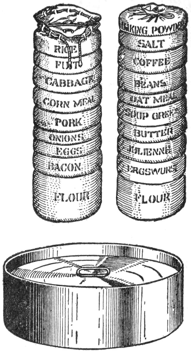
Food Bags with Friction-Top Tins to Fit Them, in Which Lard, Butter, Pork, Ham, and Other Greasy Necessities are Carried
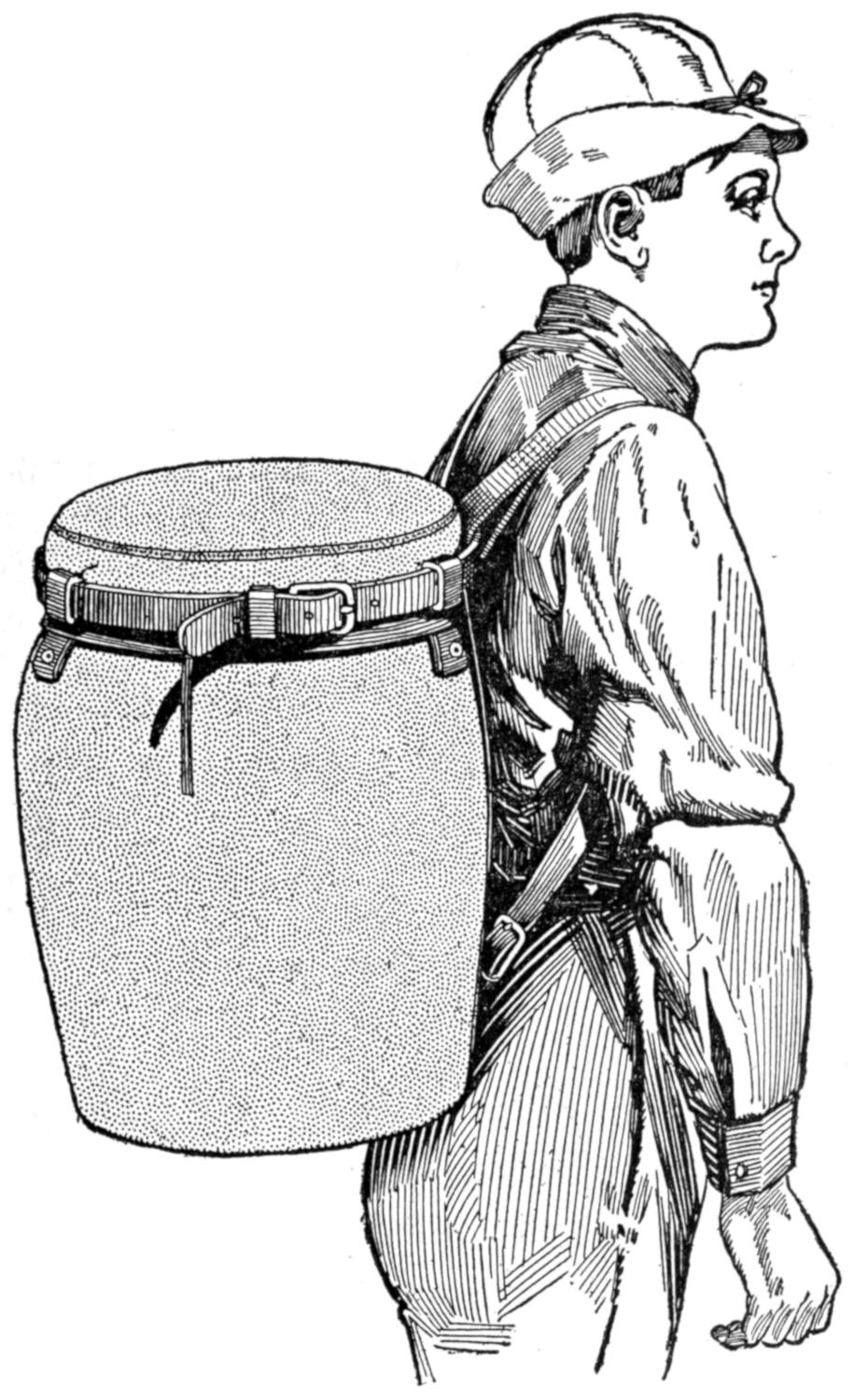
A Pack Basket with a Waterproof Canvas Lid and Cover, Having Straps to Go over the Shoulders, Is a General Favorite with Woodsmen and Guides
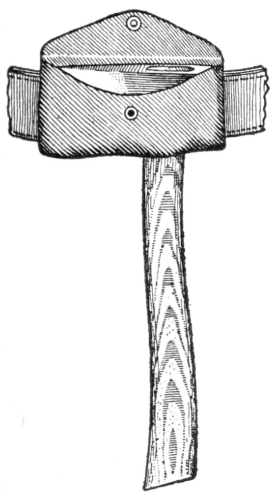
When Going Light the Belt Ax is Used
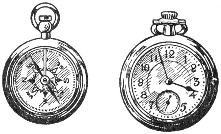
The Compass Is by Far the Most Useful Instrument for the Woods, but Any Reliable and Inexpensive Watch may be Carried
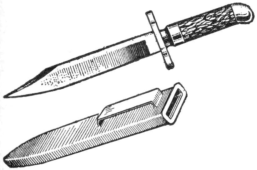
A Good, Tempered Knife Should be Worn at the Belt
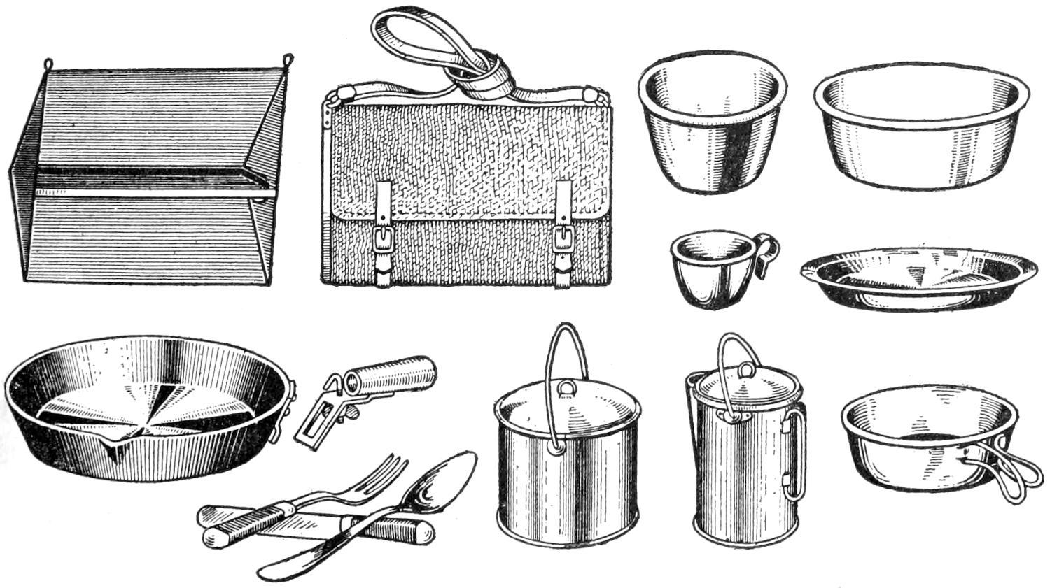
The Cooking Kit may be of Aluminum or Steel, All Nesting within the Largest Pot, and may Include a Folding Baker, or Reflector, with Bread Board in Canvas Bag, a Wood Salt Box, and a Water-Tight Can for Matches
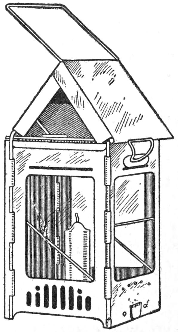
Folding Candle Lanterns are the Most Convenient for the Woods and They Give Sufficient Light for Camp Life
[114]
The personal outfit should include only the most useful articles, and each member of the party should be provided with a dunnage bag of canvas to hold bedding and clothing, and a smaller, or “ditty,” bag for keeping together the toilet and other personal belongings which most everyone finds necessary for everyday comfort. A mending kit, containing a few yards of silk, linen, and twist; a length of mending cotton; buttons; a few needles and pins, both safety and the common kinds, should not be overlooked. The veteran usually stows away a bit of wire; a length of strong twine; a few nails and tacks; rivets, etc., for emergency use, and it is surprising to the novice how handy these several odds and ends are found while in camp. A compact tin box will form a convenient place to keep them and will take up little room in the dunnage bag. A medicine case and a first-aid outfit are well worth packing; the smallest cases containing a few of the common remedies will fully meet the camper’s needs.
When carrying food by canoe or pack basket, the canoe duffel and provision bags are a great convenience, enabling the outer to carry different foodstuffs in a compact and sanitary manner. Food bags may be had in different sizes, and friction-top tins may be purchased to fit them; and one or more of these liquid-proof containers are desirable for transporting lard, butter, pork, ham, and other greasy necessities. The food bags slip into the larger duffel bags, making a very compact bundle for stowing away in a canoe or pack harness.
For permanent camps, take the wall tent with fly, although the Baker or camp-fire styles are also good. When traveling light by canoe, the canoe or protean tents are recommended. When going very light by pack, use the forester’s or ranger’s tent. Sod and floor cloths and mosquito netting are optional.
The cooking kit may be of aluminum or steel, all nesting within the largest pot. Include a folding baker, or reflector, with bread board in a canvas bag, a wood salt box, and a water-tight can for matches.
Furniture for the permanent camp consists of a full-sized ax, double-blade or tomahawk style with straight handle, in a protecting case, whetstone and file for keeping the ax in shape. A shovel and saw will be needed when a cabin is built. A canteen may be included, but is not required on most trips. A folding candle lantern is the best for the average trip, but an oil, or acetylene, lantern may be used in a fixed camp. Cots, folding chairs, tables, hangers, etc., are only useful in fixed camps.
A pack basket with a waterproof-canvas lid and cover, having straps to go over the shoulders, is a general favorite with woodsmen and guides. Canvas packs or dunnage bags may be used if preferred. There are two sizes of food bags, one holding 5 lb. and another of 10-lb. capacity, with draw-strings at the top, and these are the best for carrying provisions.
Pack harness, with a tumpline to go across the forehead, is needed when the outfit must be carried on portages, etc. This may be omitted when pack baskets are used. Packing cases of fiber may be used for shipping the outfit to the camping ground, but ordinary trunks, or wood boxes, will answer as well.
An old ordinary suit that is not worn too thin is sufficient. Corduroy is too heavy for the summer and too cold for winter, and canvas is too stiff and noisy for the woods. Cotton khaki is excellent for the summer, and all-wool khaki, or mackinaw, coat and trousers are comfortable for winter. Wool is the best material for undergarments[115] in all seasons. Two sets of garments will be sufficient, as the washing is done at night. Be sure to have the garments large enough to allow for shrinkage. Light-weight cashmere is the best material for socks during summer, and heavier weight for the winter. Three pairs of ordinary-weight and one pair of heavy-weight will be sufficient. A medium-weight gray-flannel overshirt, with breast pockets having button flaps, is the woodsman’s choice. On short and light trips one shirt will do. A light-weight, all-wool gray or brown, sweater is a good thing to carry along, it is easily wetted through and a famous brier catcher, yet most woodsmen carry one.
The regulation army poncho is more suited to the woods than a rubber coat or oilskins. The larger-size poncho is more bulky to pack, but may be used as a shelter by rigging it up with poles, lean-to fashion. A poncho makes a good ground blanket also.
A medium wide-brimmed hat, in gray or brown, is better than a cap. A gray, or brown, silk handkerchief should be included to wear around the neck to protect it from the sun and cold. Only few novices will carry one, but not so with the regular woodsman, The moccasin is the only suitable footwear for the woods. The “puckaway,” with extra sole, is known to most woodsmen. A pair of larrigans—ankle-high moccasins with single sole—are suitable to wear about the camp.
Each member of the party carries his own knapsack, or ditty bag, in which such things as brush and comb, toothbrush, razor, towel, medicines, stationery, etc., are kept. The extra clothing is carried in its own canvas bag.
Each member of the party carries a pair of woolen blankets. Army blankets in tan color are serviceable and inexpensive.
A good, tempered knife should be worn at the belt, preferably one without a hilt and having a blade 5 or 6 in. long.
A small leather pouch containing a few common remedies, such as quinine, laxative, etc.; and a small first-aid outfit should be included in each camper’s personal pack. Also a small leather pouch containing an assortment of needles, darning cotton, buttons, and a length of heavy silk twist is a handy companion.
A few sheets of paper and as many envelopes, a notebook, pencil, and a few postal cards, are usually carried, together with an almanac page of the months covering the intended trip.
The compass is by far the most useful instrument in the woods, but any reliable and inexpensive watch may be carried.
Many woodsmen carry a small hatchet at the belt, and on trips when but the few necessities are carried the belt ax takes the place of the heavier-weight tool. The tomahawk style gives two cutting edges and is therefore the best tool to carry. A leather or other covering case is needed to protect the blades.
A small tin box containing an assortment of rivets; tacks; a bit of string; brass wire; a few nails; a couple of small files; a tool holder with tools; a sheet of sandpaper; a bit of emery cloth, and any other small articles which the sportsman fancies will come in handy, may be carried. It is surprising how often this “what not” is resorted to while in the woods.
The odds and ends of personal belongings, as a jackknife; pipe and tobacco; map of the region visited; length of fishing line and hook; a few loose matches; match box; purse; notebook and pencil; handkerchief, etc., are, of course, carried in the pocket of the coat.
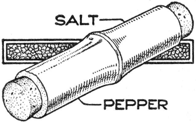
A camper will find a very clever way to carry salt and pepper by using a piece cut from a joint of bamboo. A piece is selected with the joint in the center, and the ends are stoppered with corks.
[116]
To say that the subject of this article is the simplest motor in the world is not to overestimate it, for the apparatus is not only a motor reduced to its essential elements, but combines within itself its own source of electric power, all without the use of a single piece of wire. The experiment is very interesting and instructive and will well repay a careful construction along the lines indicated, even though not in strict accordance with the dimensions given.
The first step is to procure a permanent magnet, about ³⁄₈ in. in diameter and 6 in. long. If such a magnet cannot be conveniently secured, a piece of tool steel with flat ends should be hardened by heating it to a dull red and plunging it in water, and then strongly magnetized. This may be readily accomplished by slipping a coil of insulated wire over it through which the current from a storage battery or set of primary cells is passed. If these are not at hand, almost any electrical supply store will magnetize the steel.
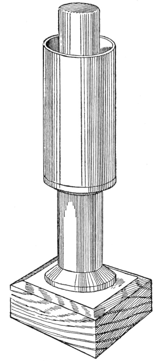
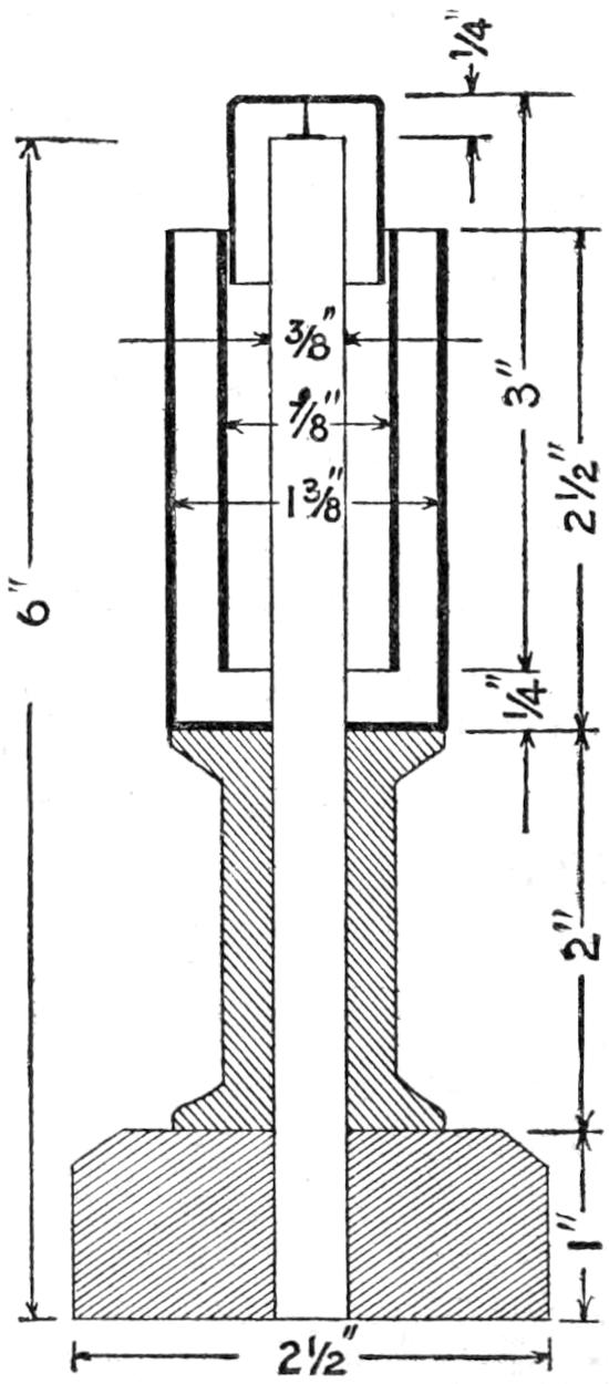
A square base block with neatly beveled corners is now in order, which is trimmed up squarely and a hole bored centrally through it to receive the lower end of the magnet. Procure a neat spool and make a hole in it large enough to pass over the magnet. Glue the spool to the base after locating it in the exact center.
The outer and larger cylinder is of copper, or of brass, copperplated on the inside. It is cup-shaped, with a hole in the bottom just large enough to permit the magnet to be pushed through with a close fit, to make a good electrical contact. The magnet may be held in place by having it closely fit the spool and the copper cylinder, and by soldering the heads of a couple of small tacks, or nails, to its under side and driving them into the spool. Coat the magnet with pitch, or paraffin, from the top down, and around its connection with the bottom of the cylinder. The small thimble shown at the top should be of brass or copper, and while one can be easily formed of sheet metal and soldered, it is not improbable that one could be made in seamless form from small article of commerce. In the exact center of the under side of the top of this thimble, make a good mark with a prickpunch, after which a small steel thumb tack should be filed to a fine needle point and placed, point up, exactly central on the upper end of the magnet, to which it is held with a little wax. The smaller cylinder is simply a piece of sheet zinc bent into a true cylinder of such a size that it may be sprung over the lower end of the thimble. This done, it is only necessary to slip the zinc over the end of the magnet until the thimble rests on the thumb tack, and then pour some dilute muriatic or sulphuric acid into the outer cylinder after which the thimble and attached zinc will begin to rotate. The required strength of the acid and the resulting speed will depend upon the nicety of suspension and the trueness of the rotating zinc cylinder. The zinc will have to be changed, but the copper undergoes no deterioration.
[117]
Cooking in the woods requires more of a knack than equipment, and while a camp stove is well enough in a permanent camp, its weight and bulk makes this article of camp furniture unsuited for transportation by canoe. Patent cooking grates are less bulky, but the woodsman can learn to do without them very nicely. However, the important item which few woodsmen care to do without is the folding baker, or reflector. The baker is folded flat and carried in a canvas case, including baking pan and a kneading board. The largest size, with an 18-in. square pan, weighs about 5 lb., and the smallest, with an 8 by 12-in. pan in aluminum, only 2 lb. In use, the reflector is placed with the open side close to the fire, and cooking is accomplished evenly and well in any kind of weather. Bread, fish, game, or meat are easily and perfectly cooked, and the smaller size is amply large for a party of two or three.
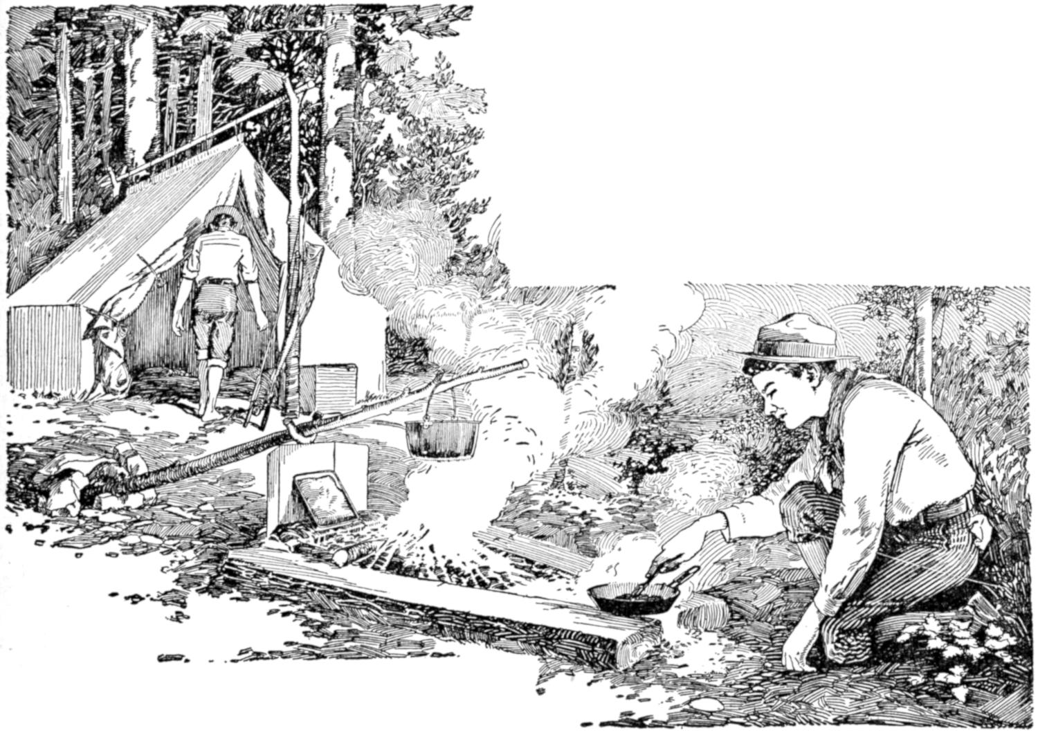
A Cooking Range Fashioned from Two Green Logs Laid in a V-Shape with a Few Stones Built Up at the Wide End over Which a Fire is Made of Hard-Wood Sticks
The camp fire is one of the charms of the open, and if it is built right and of the best kind of wood, cooking may be done over it as well as over a forest range. Many woodsmen prefer to build a second and smaller fire for cooking, and although I have never found this necessary, excepting in large camps where a considerable quantity of food must be prepared, the camper can suit himself, for experimenting is, after all, a large part of the fun of living in and off the woods.
A satisfactory outdoor cooking range may be fashioned by roughly smoothing the top and bottom sides of two green logs, and placing them about 6 in. apart at one end and about 2 ft. apart at the opposite end. At the wide end a few stones are built up, and across these, hickory, ash, and other sticks of hard wood are placed. The reflector is placed close to the coals at this end, and the fire is built between the logs, the broiling and frying being done at the narrow-end opening. Woods that burn slowly when green should be used for backlogs and end logs; chestnut, red oak, butternut, red maple, and persimmon being best adapted for this purpose.
The hard woods are best for cooking and heating, since they burn more slowly, and give out considerable heat[118] and burn down to a body of glowing coals. Soft woods are quick to catch fire, burn rapidly, and make a hot fire, but burn down to dead ashes. Hickory is by far the best firewood of the North, in that it makes a hot fire, is long-burning, and forms a large body of coals that gives an even and intense heat for a considerable length of time. Next to hickory comes chestnut; the basket oaks, ironwood, dogwood, and ash are the woodsman’s favorites. Among the woods that are easy to split are the red oak, basket oak, white oak, ash, and white birch. Some few woods split more easily when green than after seasoning, and among them are hickory, dogwood, beech, sugar maple, birch, and elm. The most stubborn woods to split are the elder, blue ash, cherry, sour gum, hemlock, sweet gum, and sycamore. Of the softer woods, the birches make the best fuel; black birch in particular makes a fine camp fire, and it is one of the few woods that burns well when green. The dry bark of the hemlock makes a quick and hot fire, and white birch takes fire quickly even though moist. Driftwood is good to start a fire with, and dry pine knots—the limb stubs of a dead pine tree—are famous kindlers. Green wood will, of course, burn better in winter when the sap is dormant, and trees found on high ground make better fuel than those growing in moist bottom lands. Hard woods are more plentiful on high ground, while the softer woods are found in abundance along the margins of streams.
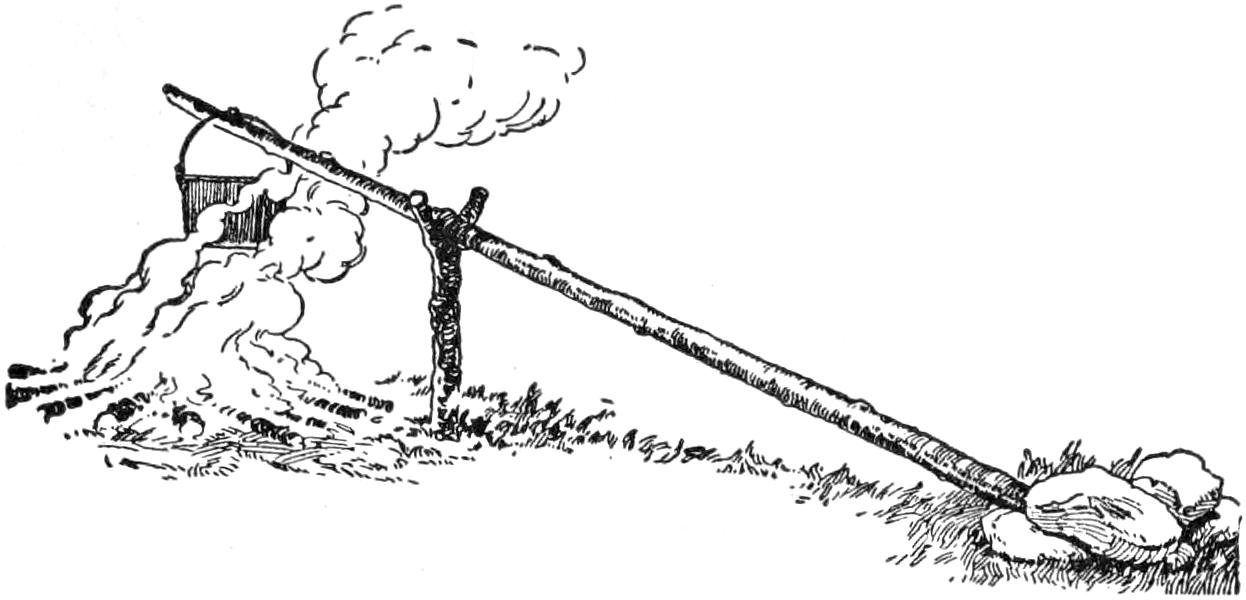
A Green Pole Placed in a Forked Stick Provides a Pot Hanger for a Noonday Meal
For cooking the noonday meal a small fire will suffice to boil the pot and furnish the heat sufficient to make a fry. Simply drive a forked stick in the ground and lay a green stick in the fork with the opposite end on the ground with a rock laid on it to keep it down, and hang the pot on the projecting stub left for this purpose. A long stick with projecting stubs, planted in the ground to slant over the fire at an angle, will serve as well. Let the pot hang about 2 ft. from the ground, collect an armful of dry twigs and plenty of larger kindling sticks. Now shave three or four of the larger sticks and leave the shavings on the ends, stand them up beneath the pot, tripod fashion, and place the smaller sticks around them to build a miniature wigwam. While the pot is boiling get a couple of bed chunks, or andirons, 4 or 5 in. in diameter, set and level these on each side of the fire, and put the frying pan on them. When the pot has boiled there will be a nice bed of coals for frying that will not smoke the meal.
When the woodsman makes “one-night stands,” he will invariably build the fire and start the kettle boiling while he or a companion stakes the tent, and as soon as the meal is prepared, a pot of water is started boiling for dish washing.
For roasting and baking with the reflector, a rather high fire is needed and a few sticks, a yard or more long, resting upright against a backlog or rock, will throw the heat forward. When glowing coals are wanted one can take them from the camp fire, or split uniform billets of green, or dead, wood about 2 in. thick and pile them in the form of a hollow square, or crib. The fire is built in the center of the crib and more parallel sticks are laid on top until it is a foot or more higher. The crib will act as a chimney, and a roaring fire will result, which upon burning down will give a glowing mass of coals.
Camp cookery implies the preparation of the more simple and nutritious foods, and in making up a list it is well to include only the more staple foodstuffs, which are known to have these qualities. Personal ideas are certain to differ greatly, but the following list may be depended upon and will serve as a guide.
[119]
This list of material will be sufficient for two persons on an outing of two weeks. Carry in a stout canvas food bag 12 lb. of common wheat flour. The self-raising kind is good, but the common flour is better. It is well to bring a little yellow, or white, corn meal, about 6 lb., to be served as a johnny cake, hot, cold, or fried mush. It is fine for rolling a fish in for frying. Rice is very nutritious, easily digested, and easy to cook. It is good when boiled with raisins. When cold, it can be fried in slices. About 3 lb. will be sufficient. Oatmeal is less sustaining than rice, but it is good for porridge, or sliced when cold and fried. Take along about 3 lb. About 2 lb. of the self-raising buckwheat flour should be taken along, as it is the favorite for flapjacks or griddle cakes. Beans are very nutritious, and about 2 lb. of the common baking kind will be required, to boil or bake with the salt pork. For soups, take 2 lb. of split peas. They can also be served as a vegetable. Salt pork is a stand-by, and 5 lb. of it is provided and carried in friction-top tins or a grease-proof bag. It should be parboiled before adding to the beans or when fried like bacon. The regulation meat of the wilderness is bacon, and 5 lb. of it is carried in a tin or bag. Carry along 3 lb. of lard in a tin or bag, for bread-making and frying. About 3 lb. of butter is carried in a friction-top tin. For making rice puddings, take along 1 lb. of raisins. About 1 lb. of shredded codfish is good for making fish balls. Other small articles, such as ¹⁄₂ lb. of tea; 1 lb. of coffee; 3 lb. of granulated sugar; 1 pt. of molasses; 1 pt. of vinegar; 4 cans of condensed milk; 1 can of milk powder, a good substitute for fresh milk; 1 can egg powder, good for making omelets or can be scrambled; 1 lb. salt; 2 oz. pepper; 1 package each of evaporated potatoes, onions, and fruits, and 3 packages of assorted soup tablets.
This list is by no means complete, but it will suffice for the average person on the average trip, since the occasional addition of a fish or game will help to replenish the stores. When going very light by pack, only the most compact and nutritious foods should be selected, while on short, easy trips the addition of canned goods will supply a greater variety.
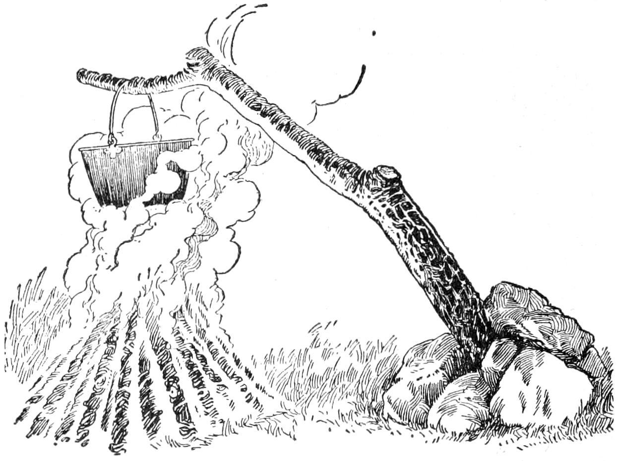
A Limb Supported at an Angle over the Fire Is Another Means of Hanging the Pot
While shooting and fishing and camping out are chapters in the book of woodcraft, the word is generally defined to mean the knack of using the compass, the map, and in making use of the natural signs of the woods when traveling in the wilderness. If the camper keeps to the beaten paths and does not stray far from the frequently used waterways, he needs no compass, and sufficient knowledge of the ways of the woods may be acquired from the previous articles, but if the outer ventures into an unknown region the value of more intimate knowledge increases as the distance to civilization lengthens, because it will enable him to keep traveling in the desired direction and prevent the “insane desire to circle,” should one discover he has lost the trail.
The woodsman well knows that it is an easy matter to stray farther from camp than he intended to when starting out, and that it is a common enough occurrence to lose one’s bearings and become temporarily lost. To prepare for this possible emergency and spend a comfortable night away from the[120] camp, he carries in his pocket a little packet of useful articles and stows away a tiny package containing a small amount of nutritious food. When leaving camp for a day’s hunting and fishing, the usual lunch is, of course, included, but in addition to this, the woodsman should carry a couple of soup tablets, a piece of summer sausage, and some tea. Wrap this in oiled silk, and pack it in a flat tin box. It will take up very little room in the pocket.
The emergency kit is merely a small leather pouch containing a short fishing line; a few fishing hooks; 1 ft. of surgeon’s adhesive plaster; needle and thread; a few safety pins, and a small coil of copper or brass wire. These articles, with the gun and a few spare cartridges, or rod; a belt knife; match safe; compass; map; a little money, pipe, and tobacco, make up the personal outfit without which few woodsmen care to venture far from camp. In addition to the above, I carry a double-edge, light-weight ax, or tomahawk, in a leather sheath at the belt and a tin cup strung to the back of the belt, where it is out of the way and unnoticed until wanted.
A small pocket compass affixed to a leather thong should be carried in the breast pocket and fastened to a button of the shirt. An instrument costing $1 will be accurate enough for all purposes. Many of the woodsmen as well as the Indians do not use a compass, but even the expert woodsman gets lost sometimes, and it may happen that the sun is obscured by clouds, thus making it more difficult to read the natural signs of the wilderness. The compass is of little value if a person does not know how to use it. It will not tell in what direction to go, but when the needle is allowed to swing freely on its pivot the blue end always points to the magnetic north. The true north lies a degree or more to either side. In the West, for instance, the needle will be attracted a trifle to the east, while on the Atlantic coast it will swing a trifle to the west of the true north. This magnetic variation need not be taken into account by the woodsman, who may consider it to point to the true north, for absolute accuracy is not required for this purpose. However, I would advise the sportsman to take the precaution of scratching on the back of the case these letters, B = N, meaning blue equals north. If this is done, the novice will be certain to remember and read the compass right no matter how confused he may become on finding that he has lost his way. The watch may be used as a compass on a clear day by pointing the hour hand to the sun, when the point halfway between the hour hand and 12 will be due south.
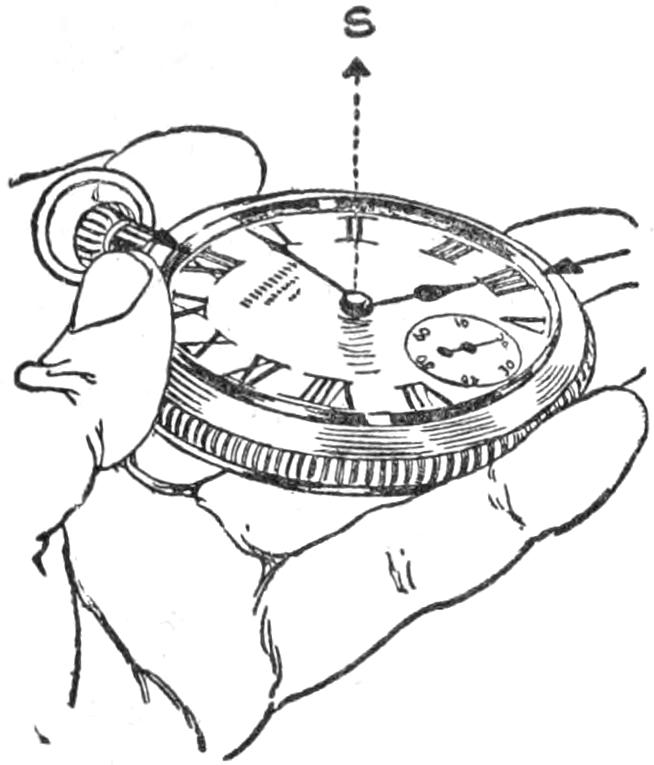
The compass needle is attracted to iron and steel, therefore keep it away from the gun, hatchet, knife, and other metal articles. Hold the compass level and press the stop, if it has one, so that the needle may swing free. Note some landmark, as a prominent tree, high cliff, or other conspicuous object lying in the direction of travel, and go directly to this object. Consult the compass frequently when making a detour, or when the landmark passes out of sight. When this mark is reached, select another farther on and continue the travel, always picking out new marks along the line indicated by the compass. When making camp, consult a map, study it, and so gain a good general idea of the surrounding country; and when leaving[121] camp, take the bearings from the compass. By so doing a person will know in what direction he is traveling, and when the course is changed, keep the general direction in mind. When climbing a hill or making detours, take a mental note of the change in direction and the bearings will not be lost.
The maps of the U. S. Geological Survey are drawn to a scale of 2 in. to the mile and cost 5 cents each. On the back of each map are printed the symbols showing the character of the land, the contours, roads, and all important rivers and lakes in the district. For convenience, the map should be pasted on a backing of cotton cloth and then cut up into handy sections. Number the sections from left to right and paste a key to the pieces on the back of one of them.
When traveling through underbrush the woodsman cannot see far ahead, and so lays a true course by noting the position of the sun. For example, here in the northern hemisphere the sun rises just south of east and sets somewhere south of due west. Therefore, if a person is going north, he should keep the sun on the back and to the right shoulder in the morning hours; full on the back at noon, and on the back and over the left shoulder throughout the afternoon.
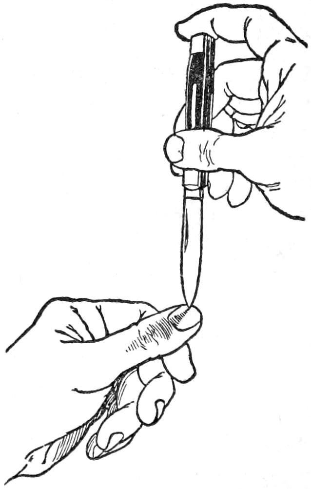
If the day is cloudy, set the point of a knife blade on the thumb nail, twist it around until the full shadow is cast on the nail, thus indicating the position of the sun.
The direction of the wind is apt to change and for this reason is an unreliable guide, while the so-called signs of the woods, such as the tips of evergreen trees pointing north, bark being thicker on the north side of trees, or moss growing thicker on the north side of the trees, are by no means to be depended upon. There is absolutely nothing in these signs. However, every woodsman is aware that the foliage of trees grows somewhat thicker on the south side, and that the branches are rather shorter and more knotty on the north side, but these and other signs are scarcely infallible, and if they were, few tenderfeet would recognize them.
When traveling by night, look for the Big Dipper or Great Bear, as the two end stars are known as the pointers, pointing to the north star.
[122]
When traveling over old and blind trails, look for the old blaze marks, and if doubtful about them, make new ones by breaking down the brushes every 15 or 20 ft., the bent part pointing in the direction of travel. If a road is encountered, it is easy to tell if it is a tote or logging road, for tote roads are crooked and wind about the trees and rocks, while the logging road is fairly straight and broad. Of course, tote roads lead nowhere in particular, but all logging roads are sure to come to a fork and lead to water. When breaking a new trail, blaze it by taking a single clip from a tree from the side it is approached, and on the opposite side make two blazes, indicating the way from the camp. If this is done, a person will always know the way back if the trail is crossed from side to side. This is the rule of the wilderness, but is not always observed to the letter, for many woodsmen blaze their trail by clipping the trees as they pass them. Be sure to blaze your own trail correctly, and when you come to a place where two roads or trails fork, set a stick to indicate the right direction.
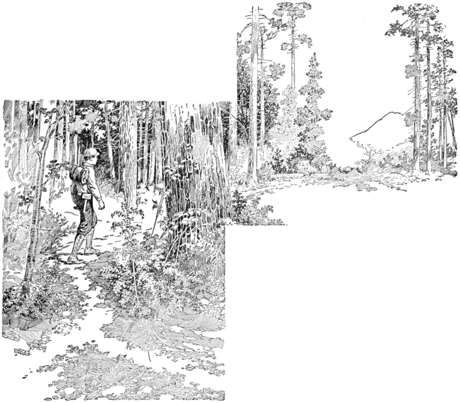
Note Some Landmark, as a Prominent Tree, High Cliff, or Other Conspicuous Object Lying in the Direction of Travel and Go Directly to the Object, and Look for the Old Blaze Marks
When a person becomes lost in the woods, as every woodsman is sure to do sometimes, sit down and think it over. Many times a person is nearer camp and companions than it is possible to realize, and if a straight direction is taken, a lumber road or a stream will be found that will give one his bearings. Above all, do not become frightened. If the emergency kit and lunch have not been forgotten, a day and night in the woods alone is not a hardship by any means. Avoid wasting energy by rushing madly about and forgetting to blaze the trail that is being made. Bend the points of the brushes down in the direction of travel Do not shoot the last cartridge to attract attention, and do not shout until hoarse. Sit down and build a fire of green wood, damp leaves or moss, so that it will smoke. Build a second fire a short distance from the first. This is the recognized signal of the one who is lost. The afternoon may be windy but the wind is certain to die away at sundown, and the smoke rising from the fires will be visible from a considerable distance. When an Indian gets lost he merely camps on the spot and awaits the next day for picking up the trail.
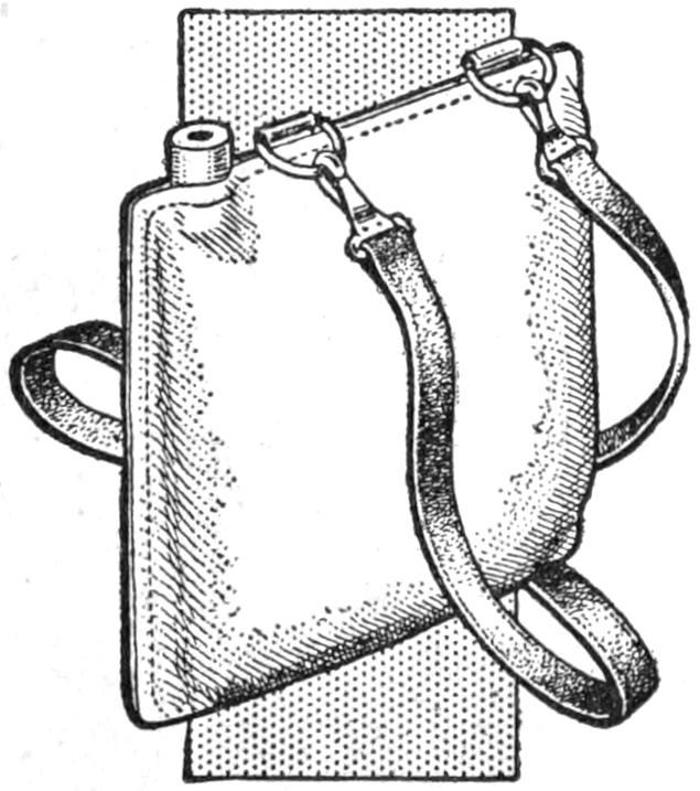
While out on a camping trip I devised a way to supply the camp with cool water. A strip of heavy canvas was cut about 2 ft. long and 1 ft. wide, and the edges were sewed up to make a sack 1 ft. square. In the upper corner a large porcelain knob insulator was sewed in for a mouth piece; the groove around it made a water-tight joint with the cloth. Two metal rings were sewed in the cloth at the top for attaching a strap to carry it. The side and top seams were made as tight as possible.
In use this sack was filled with as cool water as possible and tightly corked. It was then hung in the shade where a breeze would strike it. The water gradually seeped through the cloth and this, in evaporating, kept the contents cool. This sack also came in handy while fishing or on the road.—Contributed by Earl Zander, Three Rivers, Mich.
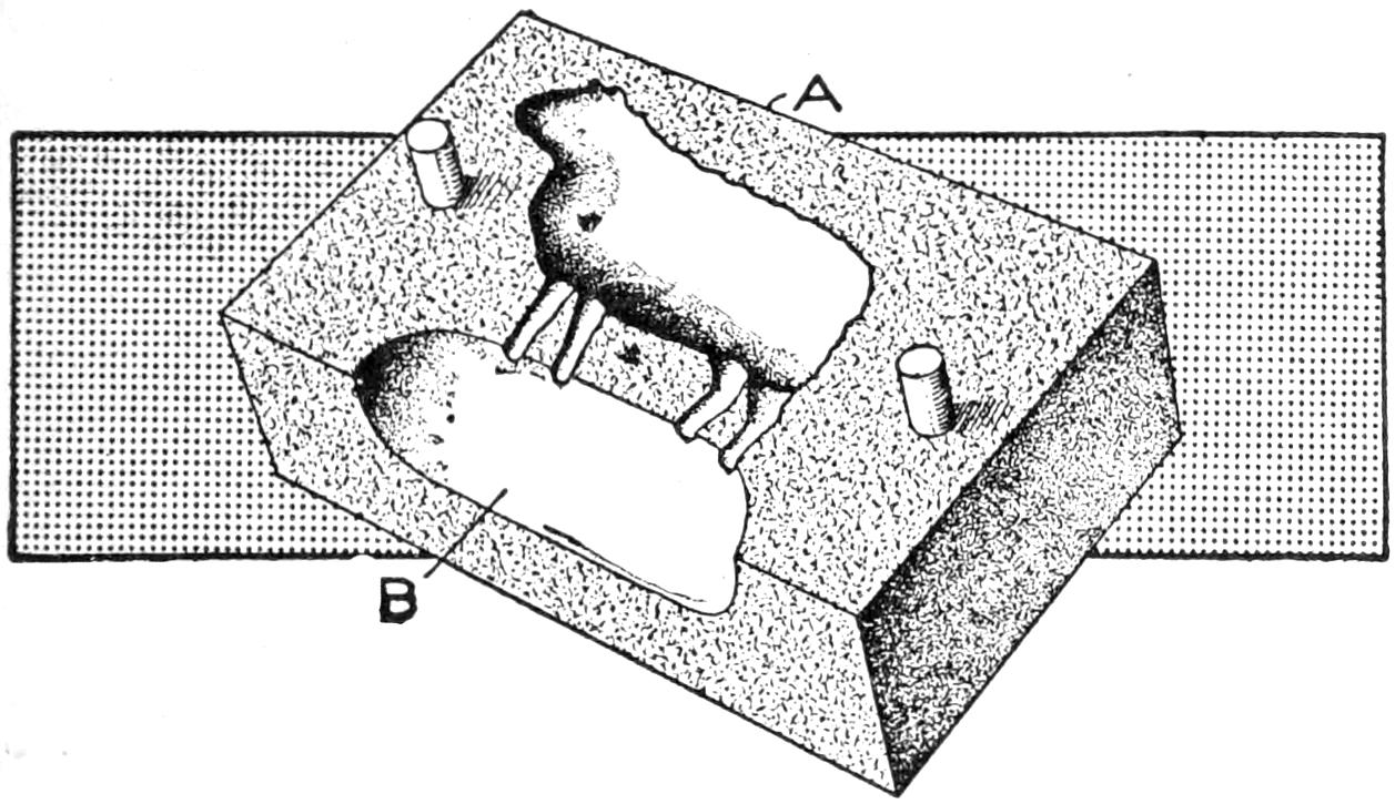
One-Half of a Mold Cut in Metal and Used in Pairs to Make Hollow Candy Objects
Those semitransparent candies made up in the shapes of animals which are brought out for the holidays and are so dear to the children have caused many to desire to know how they are made hollow. It is a little trick of the candymaker, which is perfectly clear to mechanics. The candies are cast in metal[123] molds just as babbitt bearings are cast for motor cars. One-half of such a mold is shown in the sketch. A concave recess in the face gives the shape of a horse, dog, or sheep, and another half with a similar recess is laid on and located with two dowels. In use the halves are set on a table resting on the back face A, the hot liquid is poured in at B until the mold is full, then it is allowed to set for a minute, during which the portion in contact with the cold metal hardens, whereupon the mold is turned over and the still liquid center is poured out. This leaves a glossy surface like candy, a delight to the child, that saves money for the maker and because of its thin walls makes eating easy.
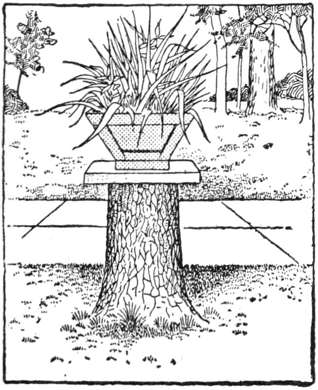
An old stump remaining after cutting down a large tree in front of a house was made into an ornamental object in the following manner: A cap was made of concrete, reinforced with a square piece of netting. A concrete vase was made and set on the cap. It is only necessary to make a square box from a few scrap boards of the desired size, built up around the stump top. A neat mixture of cement is made and poured in around it, and allowed to set.
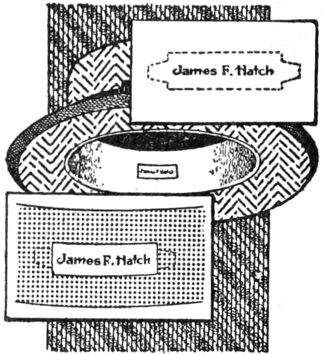
A quick and convenient way of marking a hat is to take a visiting card and cut it down in the manner shown in the illustration, then make two small slits in the sweatband of the hat and insert the ends of the card. If the card becomes soiled it can be easily replaced with another. The address can be added if desired.—Contributed by James F. Hatch, Raleigh, N. C.
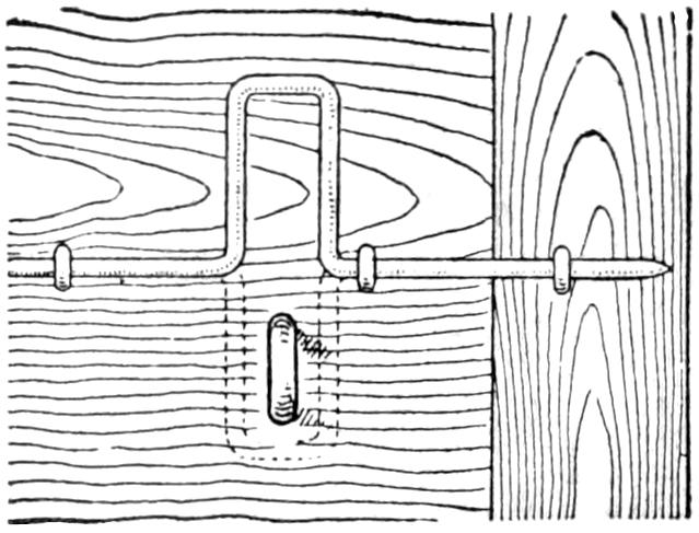
A door latch that is efficient as well as simple may be made by bending a piece of iron rod and pointing one end, as shown in the illustration, then securing it to the door with staples; or small rods may be bent in the shape of a staple and the ends threaded for nuts. The door is locked by turning the handle in the position shown by the dotted lines and securing it with a padlock.—Contributed by Claud M. Sessions, Waynesville, Ill.
Every good fisherman knows that a light will attract fish. A simple light can be made by taking a pint fruit jar, putting a ¹⁄₄-in. hole in the top of the cover, inserting a piece of gas pipe in the hole and soldering it to the cover. Insulated wires are run through the pipe, and a small electric globe is attached to the ends in the jar. The other ends of the wires are attached to a pocket battery. The jar is placed under water and the light turned on, which attracts the fish.
[124]
A very useful combination packing box and camp table may be made from a coffee or other large box. If a box with a three-ply top is available, it makes a neat appearance, but this is not essential. A box, 14 in. deep, 20 in. wide, and 29 in. long, outside measurements, is convenient, as it will slip under the seat of a spring wagon, and is of such a size that a person’s knees will pass under it when used as a table.
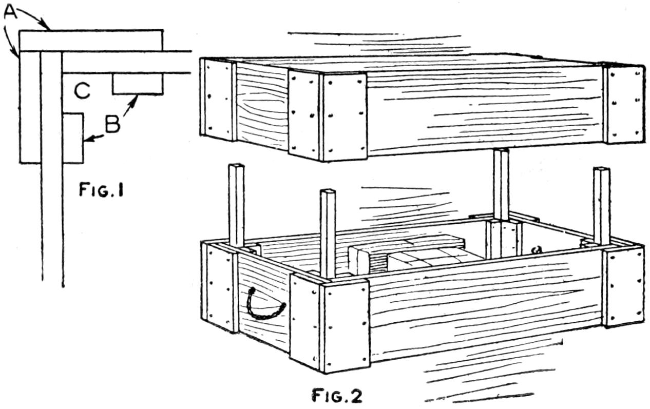
Fig. 1
Fig. 2
The Strips in the Corners of the Boxes Form Sockets for the Legs
Saw the box in two on the center line of the narrow way, making two uncovered boxes of the same size and depth. The corners of each box should be well braced on the outside, as shown at A, Fig. 1. The strips B are fastened to the inside of the box to form sockets, C, for the legs. The strips are ¹⁄₂ in. thick, 1¹⁄₄ in. wide, and as long as the box is deep. Four legs, about 12 in. long and of such size as to fit in the sockets, are used for holding the boxes together in transit. Rope handles are fastened in the ends of each box, and also a hook and eye, which are used to lock them together.
To pack the boxes place one half open side up, and insert the legs, as shown in Fig. 2. Then fill it and extend the packing to the level of the leg ends; slip the other half of the box on the legs, and fasten the two with the hooks. If properly roped, such a box will be taken as baggage. Canvas, and other articles which will be removed at once upon arrival in camp, rather than provisions, should be packed in this box, so that it can be converted into a table with the least possible work.
To make one table, or two, of the box, remove the packing legs and insert long legs in the sockets of each section. A set of eight legs, 30 in. long, take up very little space, and can be carried diagonally in the bottom of the box. A piece of oilcloth can be wrapped around them and used later as a cover for the table. The legs should fit loosely in the sockets to provide for the swelling in damp weather. Ordinarily they can be wedged to make them rigid. The table is shown in Fig. 3.
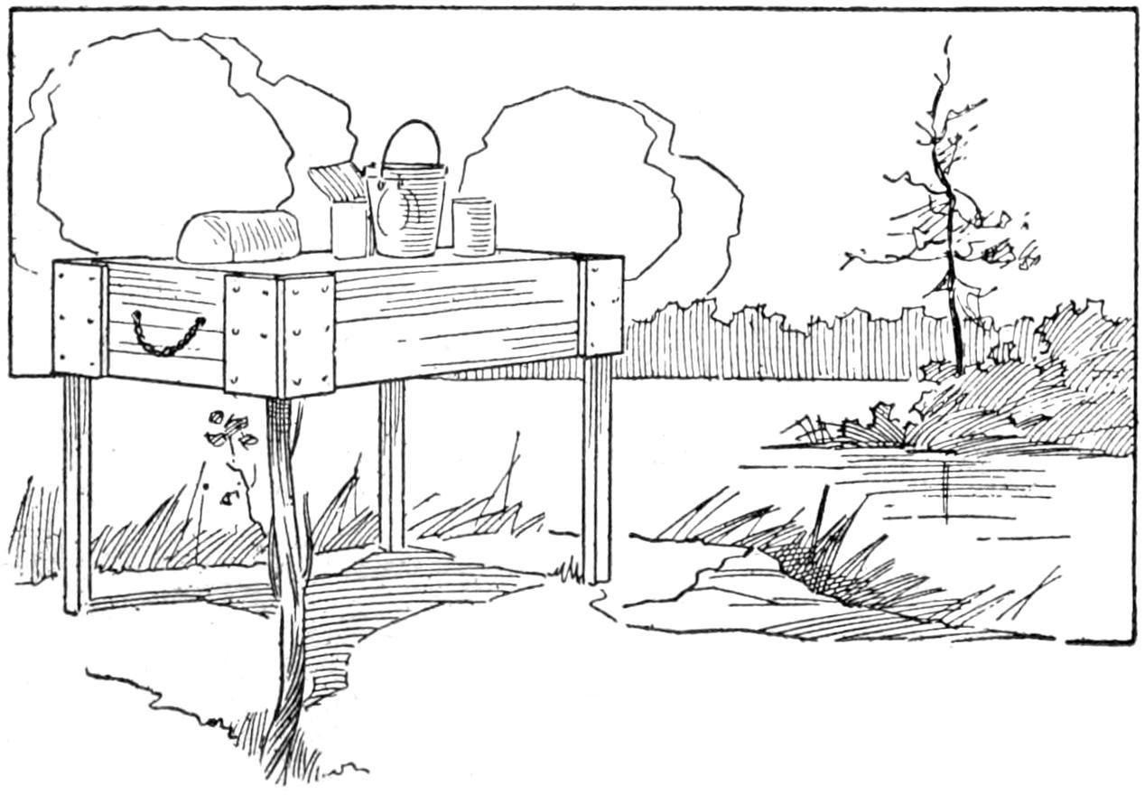
Fig. 3
Each Half of the Box Inverted is Used as a
Table Top on the Legs
Pictures can be mounted cheaply and artistically on stiff paper, to make them serviceable for decorating the summer home or camp cottage, without having them placed in a wooden frame. For this purpose a “natural-surface” drawing paper should be used, each sheet being sufficiently large to allow a border all around. With the picture properly centered and marked off, the frame can be fixed. Sets of parallel slots can be cut all around in the border, and a suitable ribbon drawn through so that it is held in place only by the narrow strips of paper. On each of the four[125] corners, a rosette, or similar decoration, can be placed. Ribbons harmonizing with the subject of the picture should be used; for example, a marine scene could have a blue ribbon; fields and brooks, some shade of green; while flowers would probably be best set off by some delicate pink shade.
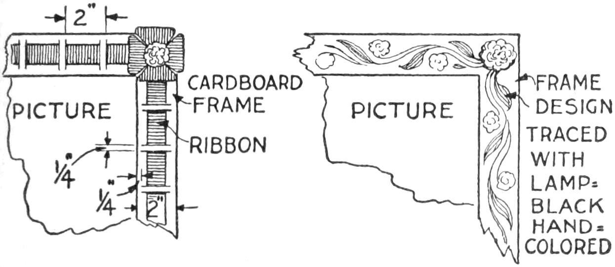
The Edges of Cardboard Extending Out from a Picture Made to Represent a Frame
Another means of decorating the border is to choose some appropriate illustration from a newspaper, or magazine, and carefully trace this outline with carbon paper all around the frame. These figures could then be colored as desired. Profile pictures are best for such work, as they are most easily traced. To be in harmony with the picture, cuts such as captains, sailors, or ships would be suitable for marine scenes; soldiers and guns, for war scenes; and trees or flowers, for landscapes.—Contributed by J. B. Murphy, Plainfield, N. J.

The Rectangular Opening Allows Only That Portion of the View to be Seen Which will Show on the Picture
Ordinary view finders on cameras, having the cut-out in the shape of a Maltese cross, are quite confusing to some camera users. To overcome this difficulty, I cut a piece of celluloid to the shape shown, and in taking a picture, the proper opening is held over the view finder so that only the view that will appear in the picture can be seen.—Contributed by E. Everett Buchanan, Elmira, N. Y.
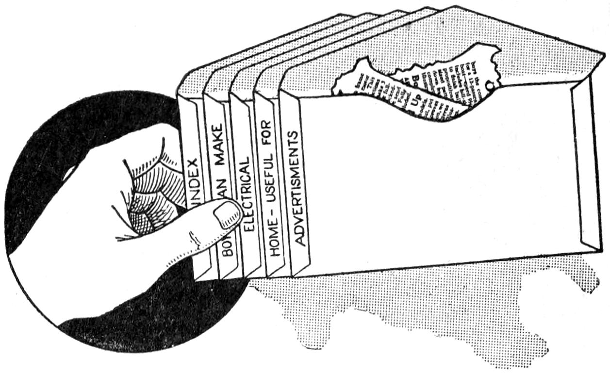
The Flaps Hold All the Envelopes Together, Producing a File of Several Compartments
Handy pockets for holding notes, or small articles, may be made by anyone from ordinary envelopes. The gummed flaps of the envelopes are stuck together after spacing the envelopes to allow a small margin at the end on which the contents of each separate pocket may be written.—Contributed by H. Goodacre, Wolcott, Ind.
Measure the bottom part of the glass and make a band of copper that will neatly fit it. The ends of the copper can be riveted, but if a neat job is desired, flatten or file the copper ends on a slant, and braze or solder them together.
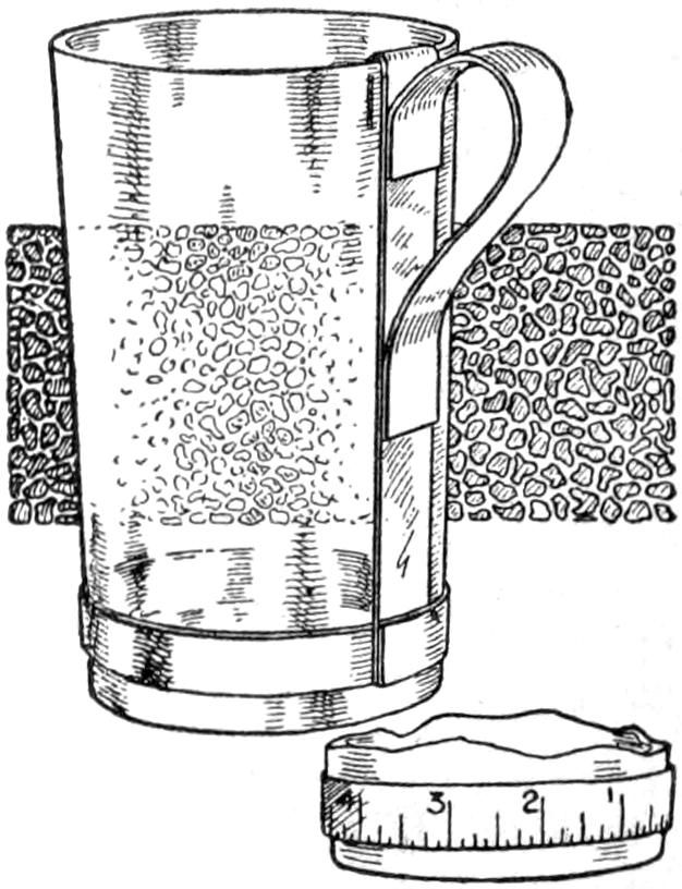
Attach to the band an upright copper piece a little longer than the glass is high. To this upright piece a bent piece of copper to form a handle is riveted or soldered. The glass is set in the band and the upper end of the vertical piece is bent over the glass edge.—Contributed by William King, Monessen, Pa.
¶A simple and handy pincushion can be made of a large cork fastened to any support or base with a nail or screw.
[126]

The combination camp-kitchen cabinet and table is the result of not being able to take the members of my family on an outing unless they could have some home conveniences on the trip, and perhaps the sketch and description may help solve the same problem for others. The table will accommodate four persons comfortably, and extra compartments may be added if desired. The cabinet, when closed, is strong and compact, and if well made with a snug-fitting cover, is bug-proof, and the contents will not be injured greatly, even though drenched by rain or a mishap in a craft.
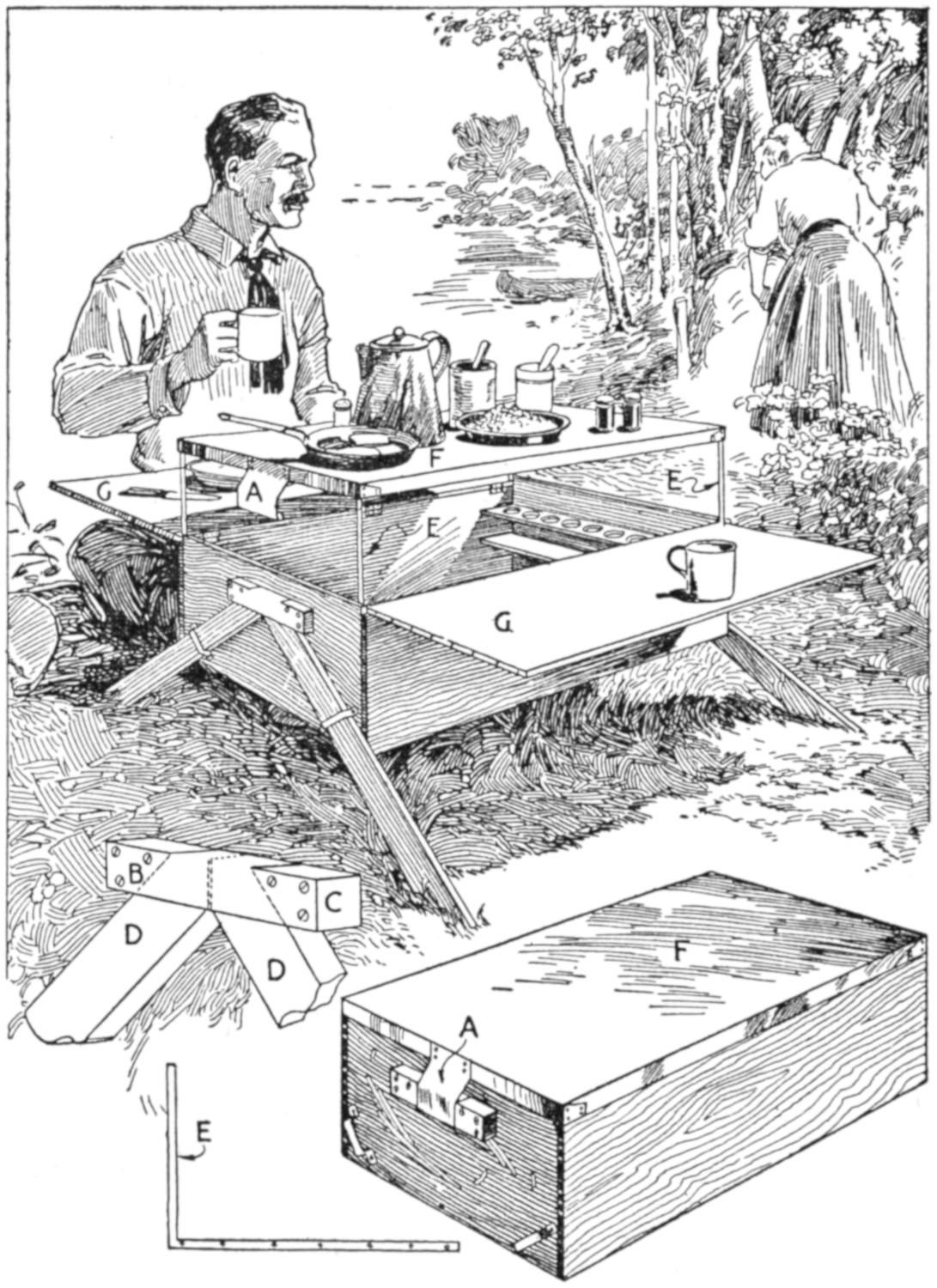
This Outfit Provides Accommodations for Four Persons, and Folds Compactly
For coffee, tea, sugar, salt, etc., I used small screw-top glass jars. They are set in pocket shelves at both ends. When closed, one can sit on the box or even walk on it if necessary when in the boat, and if an armful or two of coarse marsh grass is spread over it, the contents will keep quite cool, even when out in the hot sun. When open for use, the metal table top F is supported on metal straps, E, which also act as braces and supports for the table leaf, G, on each side of the box. This affords plenty of table surface and one can easily get at the contents of the cabinet while cooking or eating. The legs, D, are stored inside of the box when closed for traveling. They are held in place under metal straps when in use, and held at their upper ends by the metal plate and blocks, B and C. The bent metal pieces, A, on the ends of the top, spring over the blocks at B and C, and form the handles.
A serviceable circular life buoy may be made by sewing together rings of canvas, filling the resulting form with ground cork, and waterproofing the covering. Cut two disks of canvas about 30 in. in diameter, and cut out a circular portion from the center of each, about 12 in. in diameter. Sew the pieces together at their edges, leaving a small opening at a point on the outer edge. Fill the cover with cork used in packing grapes, and sew up the opening. Paint the buoy thoroughly, with white lead, and attach hand grips of rope.
[127]
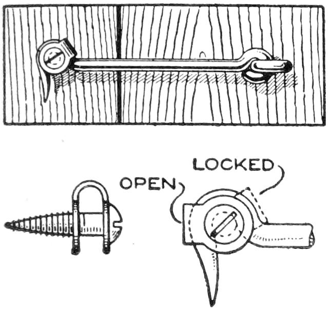
The troublesome opening of a latch hook on a gate or door, permitting intruders to enter or possibly injuring the door in the wind, can be easily overcome by fitting a small catch over the hook, as indicated in the sketch. The U-shaped locking device is cut from a piece of tin, and fastened on the screw over which the hook is set. When locked, it is pushed back over the head of the hook, and cannot be easily jarred out of place.
A trick which is interesting and amusing for the entertainment of the home audience, is performed with a derby hat and a gentleman’s cuff. The effect is produced as follows: The performer takes the derby from his head and shows that it is empty. He removes one of his cuffs and drops it into the hat. He tips the hat over so that the spectators can see the inside, and the hat appears empty. He then shakes his arm, and the white cuff reappears, whereupon he places the hat back on his head. The explanation is simple: The white cuff, dropped into the hat, contains a false cuff link, and the inside of the cuff is painted black. A thread holds the cuff in shape until the latter is dropped into the hat, when the thread is broken without the spectators being aware of it. The cuff just fits into the hat, and its ends are deftly snapped beneath the hatband, the hat thus appearing empty. The duplicate cuff is kept on the forearm of the performer, and with a shake, slides into place.—Merritt Hale, Hartford, Conn.
¶A little fresh developer added occasionally to old developing solutions will bring them up in speed and intensity.
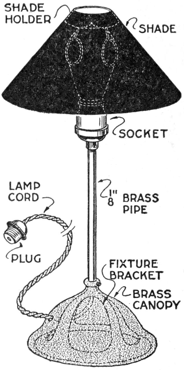
A small table lamp that is light and easily portable, can be made at a cost of less than $1 from electrical-fixture parts, either old or purchased at a supply store for the job. The base is a bracket, with its brass canopy inverted, as shown. The upright is a ¹⁄₈-in. brass pipe, and it is fitted to a standard socket. The shade holder can be made complete from a strip of tin and two wires; or adapted from a commercial shade holder used for candlesticks. Various types of shades, homemade if desired, can be used.
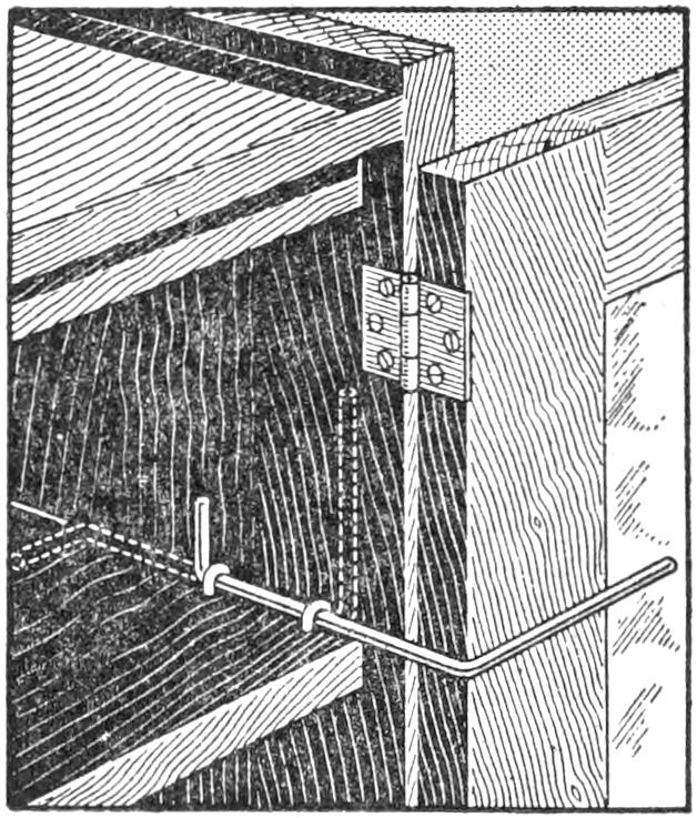
Doors of cabinets often have an annoying tendency to swing shut when articles are being removed from the shelves. To overcome this trouble with a kitchen cabinet, I fitted brackets of No. 9 gauge wire into the sides of the cabinet, the wire being bent to the shape shown in the sketch. When the doors are to be held open, the wires are slid forward from their original position, as indicated by the dotted lines, and set in front of the doors. Before the doors are closed, the wires are quickly snapped back into place.—A. S. Thomas, Amherstburg, Ont., Canada.
[128]
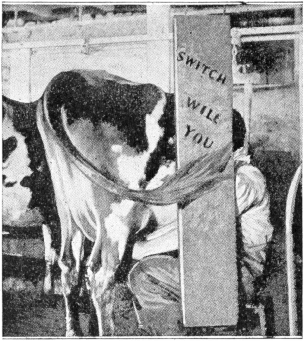
The Legend Put On the “Switchboard” by the Boys Shows How They Value It
A simple and effective device for guarding a person milking a cow from being hit in the face by the cow’s tail is made of a board, about 10 in. wide and 5 ft. long. This is hung by two wire hooks from a long wire running lengthwise of the stable just over the front edge of the gutter. It is moved along with the milker and effectually protects his face while milking. The device was made by a Wisconsin farmer after nearly losing the sight of an eye in being hit by a cow’s tail. He tried tying the tails of the cows while milking them, but found by actual test that some cows dropped down as much as 25 per cent in milk production when their tails were tied. The “switchboard” gives the cows the necessary freedom.—D. S. B., Wisconsin Live Stock Breeders’ Association.
“Friend wife” does not complain any longer because of poor light over the kitchen stove. The windows in the kitchen were so disposed that the light was partly shut off from the stove by the person standing before it. I solved the difficulty in this way: A small window was cut directly back of the stove, in a partition between the kitchen and an adjoining storeroom, locating it just a few inches above the top of the stove. A mirror was placed, after some experimenting, so that the light from an outside window in the storeroom was reflected through the small window in the partition and onto the top of the stove. Plenty of light was thus afforded. Various adaptations of this arrangement may be worked out.—F. E. Brimmer, Dalton, N. Y.
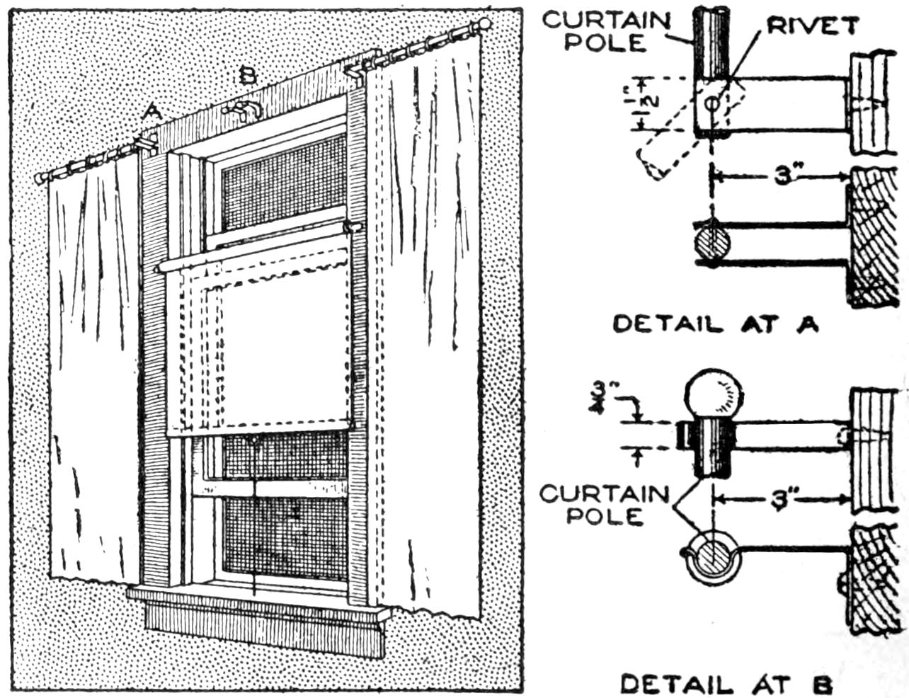
This Arrangement of Curtains and Shade Permits Through Ventilation in the Sleeping Room
Curtains, shades, and similar fixtures, often interfere with the proper ventilation of sleeping rooms. By arranging these features as shown in the sketch, the ventilation is not interfered with, and the shades and curtains give the same service as with the usual arrangement. The curtains are hung singly on hinged bars, which may be homemade or those used as towel bars. Details of the supports, at A and B, are shown in the sketch. Two pairs of fixtures are provided for the shade, permitting it to be lowered at night, with free circulation of the air at the top and bottom. The shade is quickly raised, and the curtains swung into their closed position.—J. E. McCoy, Philadelphia, Pa.
[129]
A rubber piece that held the glass container on a wall coffee grinder wore out, so that the glass would not stay in, putting the grinder out of commission. The piece worn out was a thick rubber washer, tapered at one end to form a hollow in the other, when in place. I cut a section from the thick end of a standard rubber faucet plug, and shaped it to the form of the desired washer. By removing the old rivet carefully, I was able to use it in fixing the new washer into place, and the mill was soon grinding merrily, as of old.—M. T. C., Chicago, Ill.
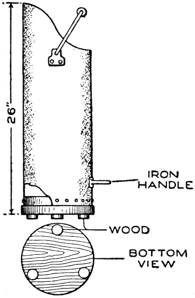
When my coal hod became worn out, I made one of a length of 8-in. galvanized-iron pipe, and found it to be handier and stronger than the kind I had used. I fitted the pipe with an iron handle and with a bail of strong wire, set in metal eyes riveted to the pipe. The upper end was cut to the curved shape shown, and the lower end square, and holes were punched along the edge for fastening it with nails to the double bottom of wood. Three wooden pads were set under the bottom, so that the hod stands easily on a spot that is not quite level.—T. E. Roberts, Toronto, Canada.
When the tag or end fastening comes off of a shoe lace, take a little black sealing wax, and press it carefully around the end of the lace and shape it to a point. This will last a long time, and does away with the annoyance of frayed lace ends.
An armchair suitable for a dressing table was made by a handy woman from pine strips. The photograph shows the simple and pleasing lines of the construction. Aside from the board seat, only three sizes of wood are used, 2 by 2 in., 1 by 2 in., and ¹⁄₂ by 2 in. The pieces are fastened with screws, round-head brass ones being used at exposed points. The seat is wider from side to side than from front to back. Two coats of white paint and one of white enamel give a good finish.
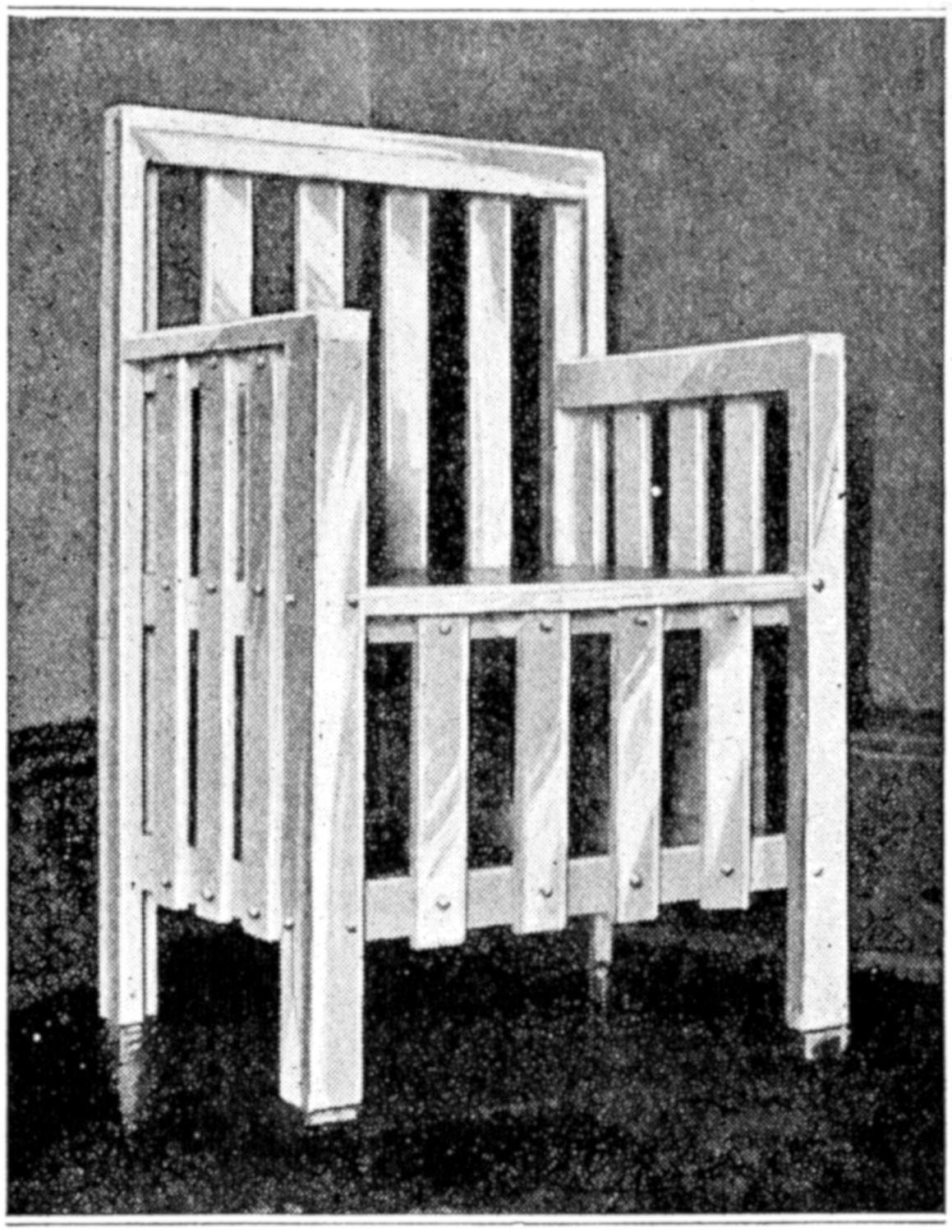
The Simple Construction of This Neat Armchair Makes It an Attractive Job for the Amateur Craftsman
The dimensions may be varied to suit individual needs. Sizes suggested are: back, 32 in. high and 24 in. wide; side, 26 in. to top of arm and 19 in. wide; seat, 17 in. from floor, 18 in. from front to back, and 20 in. wide between the front supports. The stock is all planed up square to dimensions, and sandpapered smooth. The ends should be cut squarely in a miter box, with a fine-toothed saw, and then sandpapered smooth, taking care not to round the ends.—A. May Holaday, Chico, Calif.
[130]
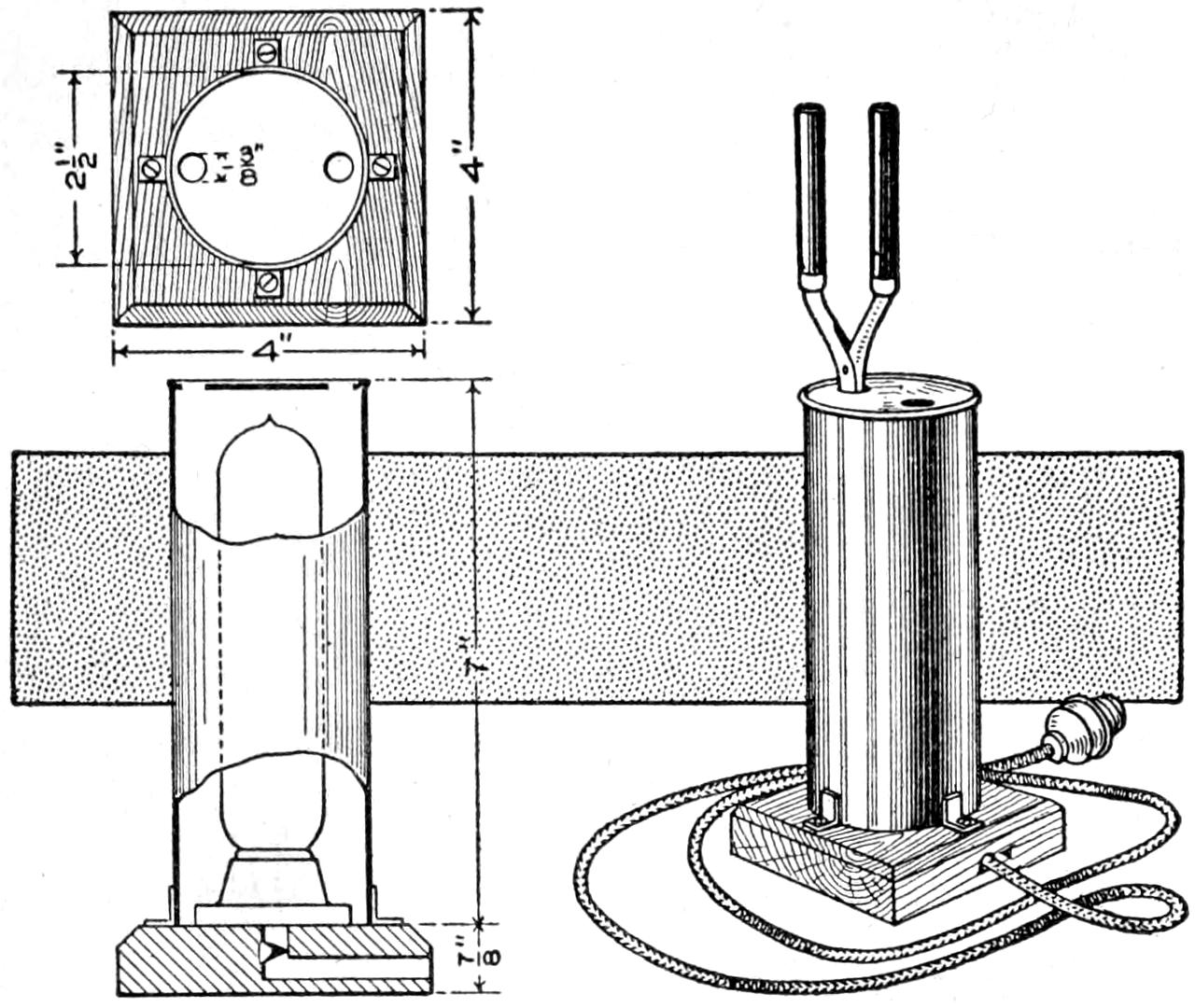
This Efficient Electric Heater for Curling Irons can be Made Quickly and Is Safer to Use than an Open Flame
Heating of curling irons is a not uncommon source of fires, and to minimize this danger, an electrical heating device is valuable. In the arrangement shown, a long candle-shaped incandescent lamp is mounted in a suitable can, or metal tube, to form the body of the heater. This should be bright, both inside and out, and preferably nickeled. Two irons can be heated by setting them in the holes in the top. Four small brackets, soldered, as shown, around the edge of the can, hold it to the base. A porcelain lamp receptacle is used, mounted on a base block. Stain, fill, and finish the wood as desired. In assembling the parts, screw the receptacle to the base, and connect the flexible cord through a suitable hole. Screw in the lamp, and fasten down the body.—John D. Adams, Phoenix, Arizona.
The best imitation mother hen for incubator chicks that we have found, is built by attaching rag strings to the bottom of an inverted cracker, or similar, box, which accommodates 2 doz. chicks. The rag pieces are torn 1 in. wide, from coarse cloth or gunny sacking, and their loose ends just touch the floor. They are placed close together. An inlet to the mother box is cut in the edge of it. The chicks huddle in among the string rags, keeping safe and warm, whereas without such an arrangement, they may crowd together too closely, and some of them be smothered.—J. Cecil Alter, Salt Lake City, Utah.
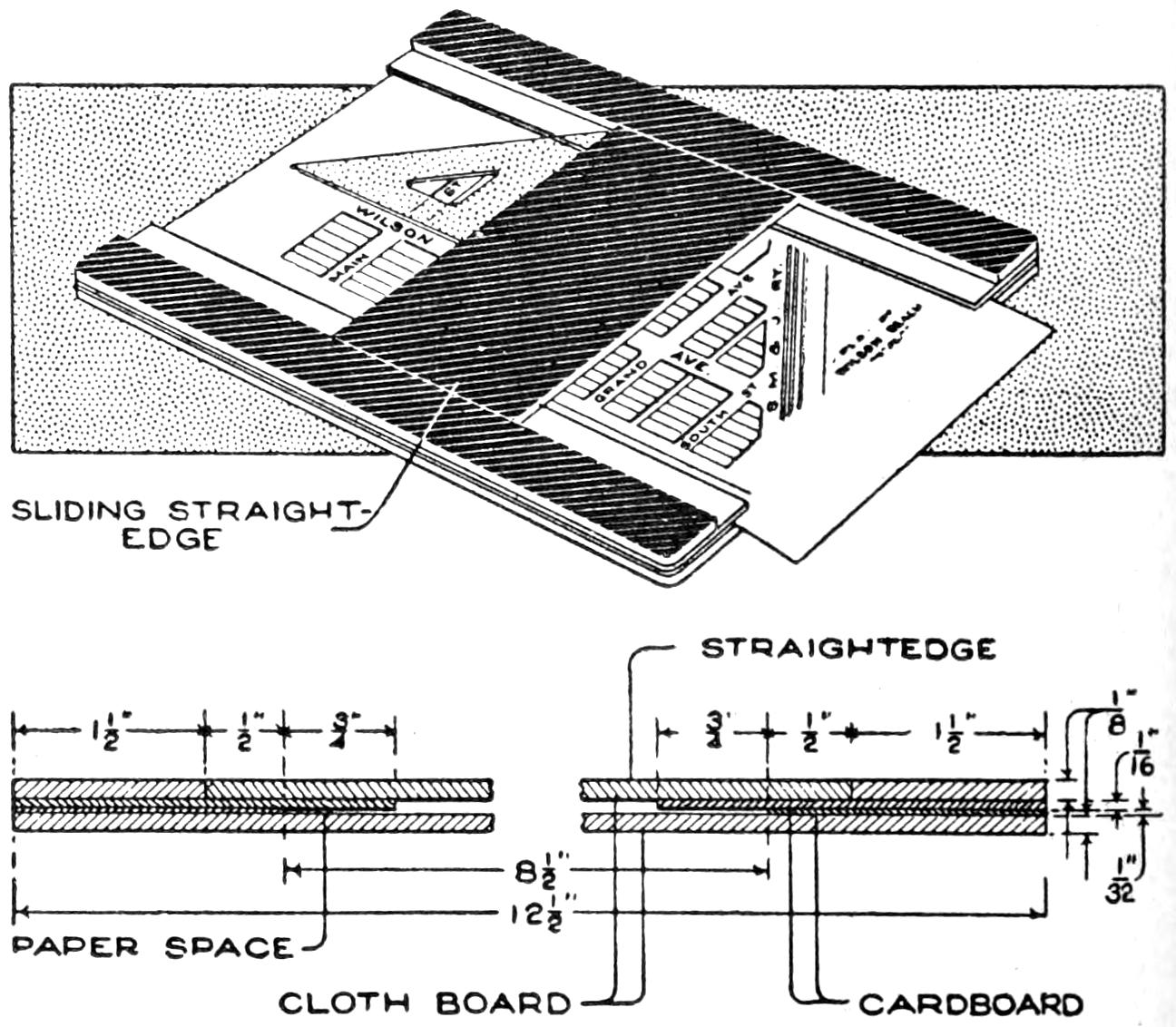
Manuscripts with Drawings may be Prepared Neatly and Quickly by the Use of This Homemade Writing Pad
Where neatness is desired in the writing of themes, manuscripts, etc., especially if sketches are set into the copy, a homemade writing and drawing pad is useful. The one shown in the sketch can be made easily, and is a handy device for school children as well as older persons. The paper is placed under the guide strips, as shown, and is moved along under the sliding straightedge as desired. Drawing instruments can be used handily along the straightedge, as indicated. The pad is built up as detailed in the sectional views. The general dimensions can be varied. The bottom piece is ¹⁄₈-in. cloth board. The second layer is ¹⁄₃₂ in. thick and of cardboard; the next is ¹⁄₁₆-in. cardboard, and the upper layer is ¹⁄₈-in. cloth board, similar to the straightedge. The latter rests on the projecting guides for the paper, and is set between the shaded sidepieces.—R. S. Edwards, Walla Walla, Wash.
[131]

After sleeping under various kinds of canvas coverings and not finding any of them entirely to my liking, I made the tent shown in the illustration, which proved quite satisfactory. It is of light weight, easily set up or taken down, and when buttoned closely is practically rain, wind, and bug-proof. The cost of materials necessary for making it is comparatively slight. I use it not only as a sleeping tent but also as a carry-all in packing camping equipment. The canvas is supported by frames made of pliable branches cut in the woods.
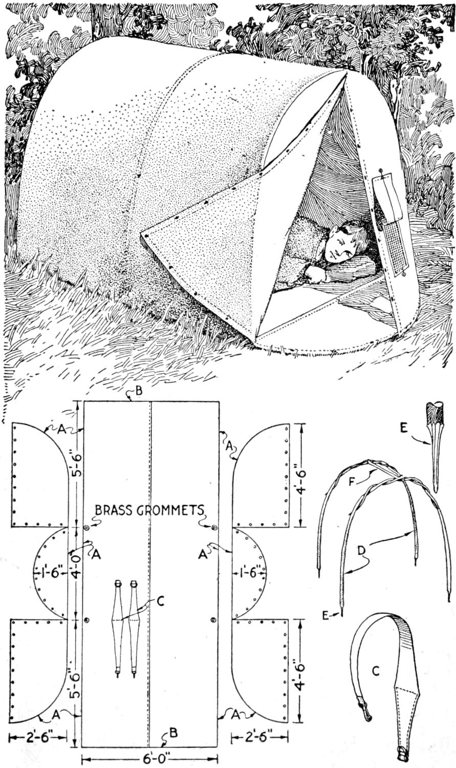
Stakes, Rope Braces, and Supporting Poles are Not Required for This Shoulder-Pack Tent, the Supports being Cut at the Camp
The layout for the canvas is shown in the detailed drawings. The sections for the ends are made of three pieces, one for the ground and two, divided vertically, for the end covering. The ground section of the main portion of the tent and the covering are made in one piece, 6 ft. wide, joined at the middle, as shown. The adjoining edges A are sewed together and the edges B, which are set at the ridge of the tent, are sewed, after the other pieces are joined. Brass grommets are fitted in the canvas, as indicated, and the points of the supporting frames pass through them in driving the supports into the ground. The shoulder straps C are placed so that they are in position when the tent is folded, and rolled into a pack. Other equipment may be placed inside of it. The tent supports D are pointed at the ends E, and are twisted together at the top. The ridge pole F steadies them and holds the canvas at the middle.
To set up the tent, lay the canvas flat on the ground and place the supports, twisted together, through the grommets. Spring them into the ends of the canvas, and insert the ridge pole by springing it between the supports. The canvas is 8-oz. duck, and the fastenings used are snap buttons; buttonholes, buckles, or harness snaps may also be used.
[132]
With a view to provide all the needs of a commissary department for 36 boys for a period of four days, either on a hike or in a permanent camp, the kitchen illustrated was constructed. As it is placed on two wheels, which are removed when the kitchen is in use, it can be moved from one day’s camp to another by attaching it to the rear of a horse-drawn wagon by means of a shaft. When the wheels are removed the entire outfit rests on legs, which are swung down from the bottom. The sides and one end are opened by swinging one half up and resting it on the top, while the other half swings down to a horizontal position where it is used as a work board, making all parts easily accessible.
The outside dimensions of the kitchen, when closed and in the form of a large box on wheels, are 5 ft. 3 in. long, 3 ft. wide, and 2¹⁄₂ ft. high. The main feature of this entire kitchen is its compactness. At the front, and extending about 1 ft. back, is a kitchen cabinet where the plates, sugar, salt, flour, etc., are kept in separate compartments. Here also are found the necessary cooking utensils, such as bread knives, butcher knives, cleaver, cooking spoons, pancake turner, sieves, large forks, lemon squeezer, etc.; and on the shelves of galvanized iron small boxes and packages of baking powder, cocoa, etc., are placed. This entire compartment, as well as all others where food is handled and prepared, is lined with No. 28 gauge galvanized iron which makes sanitation a feature also.
Upon passing around to one side there can be seen a large three-shelved oven, 21 in. wide, which is heated by a gasoline burner. Between the burner and the bottom of the oven are located coils of pipe for heating water, and these coils are connected with a tank of 7-gal. capacity, located just above the oven. An air valve and glass gauge are attached to the tank.
The next compartment to the rear is a large storage space, extending all the way through the kitchen, and a 2¹⁄₂-gal. forged-copper gasoline tank occupies a shelf in the upper portion of this space. At the rear end along this side are located nickelplated faucets which are connected with the hot-water tank mentioned; a 7-gal., white enameled milk tank above; an 18-gal. cold-water tank, and an ice-water tank, used when distilled-water ice can be secured. These faucets all drain into a small sink, which, in turn, drains off through an ordinary sink drain to a hole dug in the ground beneath it. Practically the entire rear end of the kitchen is occupied by the large water tanks, ice box, and milk tanks, with the exception of a small space at the bottom where the silverware is kept in a drawer.
On the other side, and to the rear, two compartments above and below the large water tank form excellent storage space for ham, bacon, sausage, preserves, butter, etc., which need to be kept in a cool place. Next in line is the other end of the large storage place which extends through from the other side. Pans, pails, canned goods, larger packages, etc., are kept in this space.
Immediately to the rear of the kitchen cabinet, on this side, are located compartment shelves where the tin cups are kept, and adjoining this is found a three-compartment steam cooker. By having the cups and plates near this steam cooker, which is also heated by a gas burner, there is less danger from rust, as they are kept thoroughly dried. Wherever there is a gasoline burner the compartment in which it is located is not only lined with galvanized iron, but asbestos in sheets is placed on the inner side, so that the heat will not ignite the interior packing or the woodwork. The tanks are accessible from the top of the kitchen for filling and cleaning, and are packed with ground cork.
The kitchen has shown its efficiency by giving satisfactory service in camps of many members.
[133]
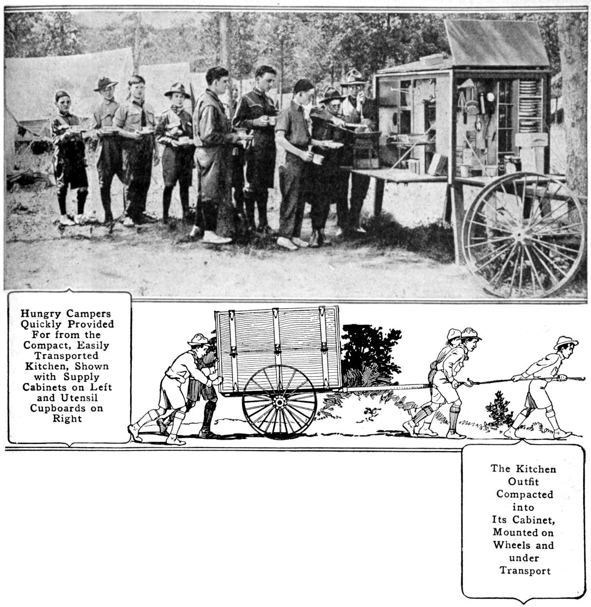
Hungry Campers Quickly Provided For from the Compact, Easily Transported Kitchen, Shown with Supply Cabinets on Left and Utensil Cupboards on Right
The Kitchen Outfit Compacted into Its Cabinet, Mounted on Wheels and under Transport
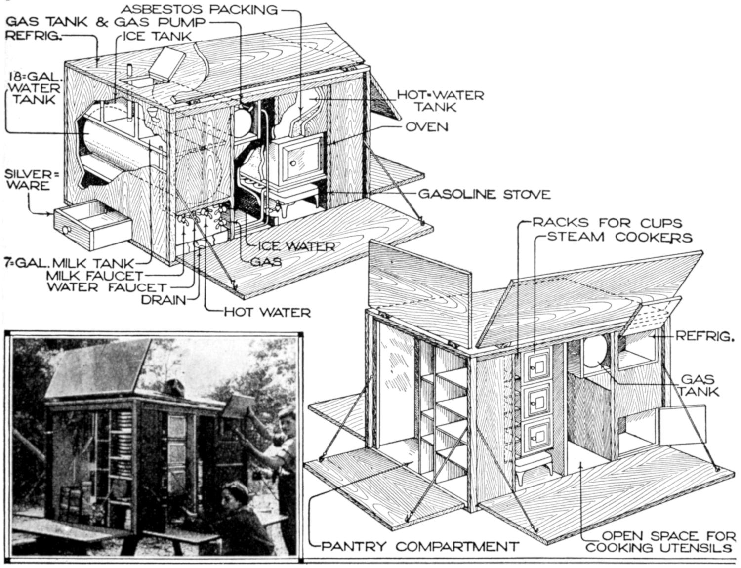
The Portable Kitchen Outfit Opened, Exposing the Various Compartments Arranged So as to Be Convenient: Above, Stove and Cooking Compartments; Below, Pantry Compartment and Space for Utensils
[134]
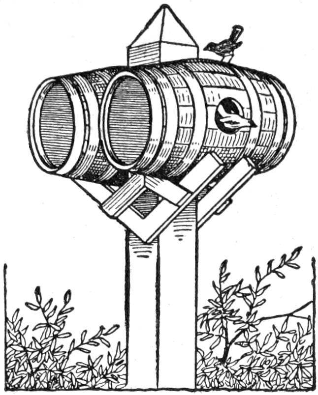
Two ordinary nail kegs, or other small kegs, will make a good bird house. They should be mounted on a square post with braces of light wood, as shown. The openings for the entrance can be cut in the ends or sides, as desired. If cut in the sides, be sure to make the hole between two staves.
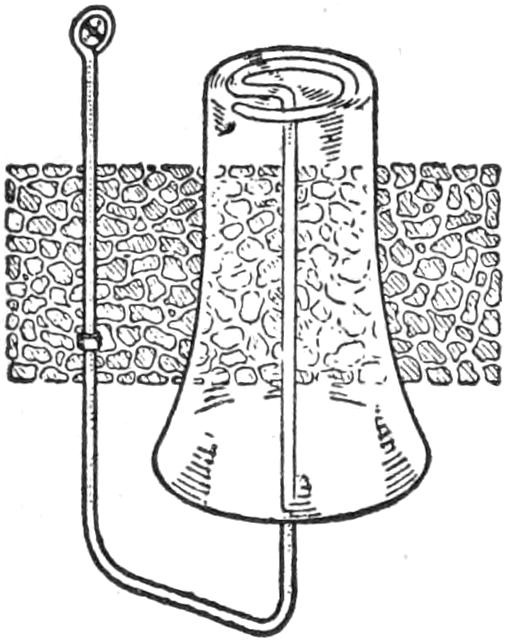
To make a glass holder quickly, shape a wire as shown in the sketch. The wire should be of sufficient size to hold the glass firmly. It is fastened to the wall, or support, with a screw and a staple.—Contributed by Edwin P. Stott, Chicago, Ill.
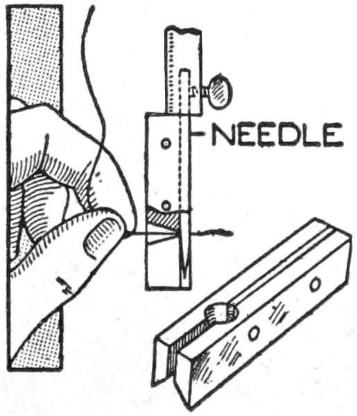
The threader consists of two brass pieces riveted together so that they will make an extension conical hole for the thread to enter freely. The length of the pieces should be such that when the upper end of the threader is placed against the needle-holder end, the conical hole will coincide with the hole in the needle. A piece of thin sheet metal is placed between the pieces above the conical hole to make an opening below for the thread to pass through when the threader is removed. The opposite edges of the brass pieces from the large part of the conical hole are filed to a bevel so that when they are riveted together they will form a V-shaped groove to center the needle.—Contributed by Harriet M. Kerbaugh, Allentown, Pa.
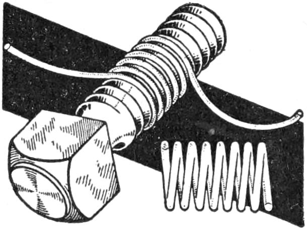
When a helical spring is needed badly, one can be made up quickly by winding the wire around in the threads of an ordinary bolt. An accurate spring can be formed, and the pitch between each coil will be exact for the entire length. In removing the spring from the bolt, grasp the coil in one hand and turn the bolt with the other.
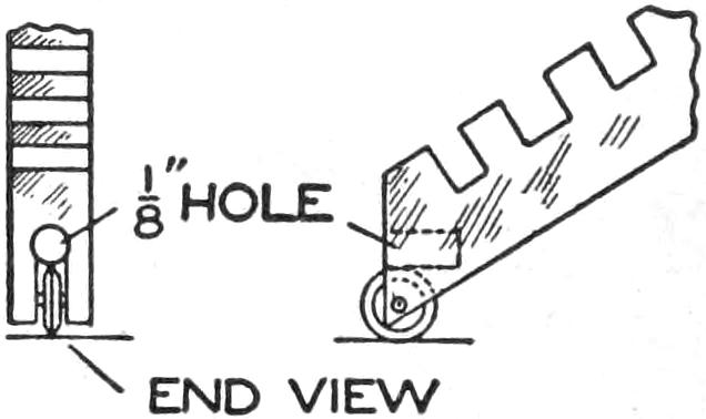
A ruling pen that will do neat work and not leave any ink on the ruler, and which with its small ink fount draws many lines at one filling, can be made from an old discarded revolving-wheel glass cutter. A ¹⁄₈-in. hole is drilled in the body, or handle part, just above the wheel. The hole is filled with a piece of felt—a piece cut from an old felt hat will do—rolled to fit snugly, so that it will bear lightly against the wheel. The felt is soaked with the ink to be used, and the pen is ready for use.—Contributed by Bert Fish, Rochester, N. Y.
¶An excellent method of closing a crack in a wall before papering is to paste a thin strip of linen over the crack. This not only makes a smooth job, but prevents the paper from tearing, should the crack widen.
[135]

A boat that is inexpensive, easily made, and readily transported is shown in the illustration. Since the bow section folds inside of the stern portion, it is important that the dimensions be followed closely. The material used is ⁷⁄₈-in. throughout.
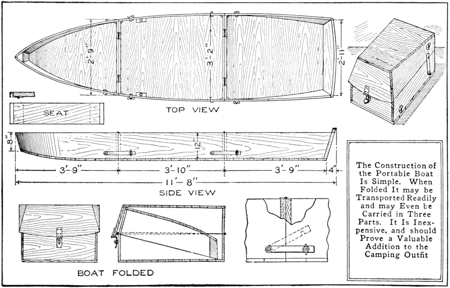
The Construction of the Portable Boat Is Simple. When Folded It may be Transported Readily and may Even be Carried in Three Parts. It Is Inexpensive, and should Prove a Valuable Addition to the Camping Outfit
Make a full-size diagram of the plan to determine the exact sizes of the pieces. Brass screws are best for fastening this type of work, but copperplated nails may be used. Tongued-and-grooved stock is best for the bottom. The joints should not be driven together too firmly, to allow for expansion, and all joints in the boat should be packed with red lead or pitch.
The adjoining ends of the sections should be made at the same time, to insure a satisfactory fit when joined. Braces are fixed into the corners.
Metal straps hold the sections together at the bottom of the hinged joints. These should be fitted so that there is little possibility of their becoming loosened accidentally. The front end of each strip is pivoted in a hole, and the other end is slotted vertically on the lower edge. Their bolts are set firmly into the side of the boat, being held with nuts on both sides of the wood. A wing nut, prevented from coming off by riveting the end of the bolt, holds the slotted end. Sockets for the oars may be cut into hardwood pieces fastened to the gunwales. The construction of the seats is shown in the small sketch at the left.
[136]
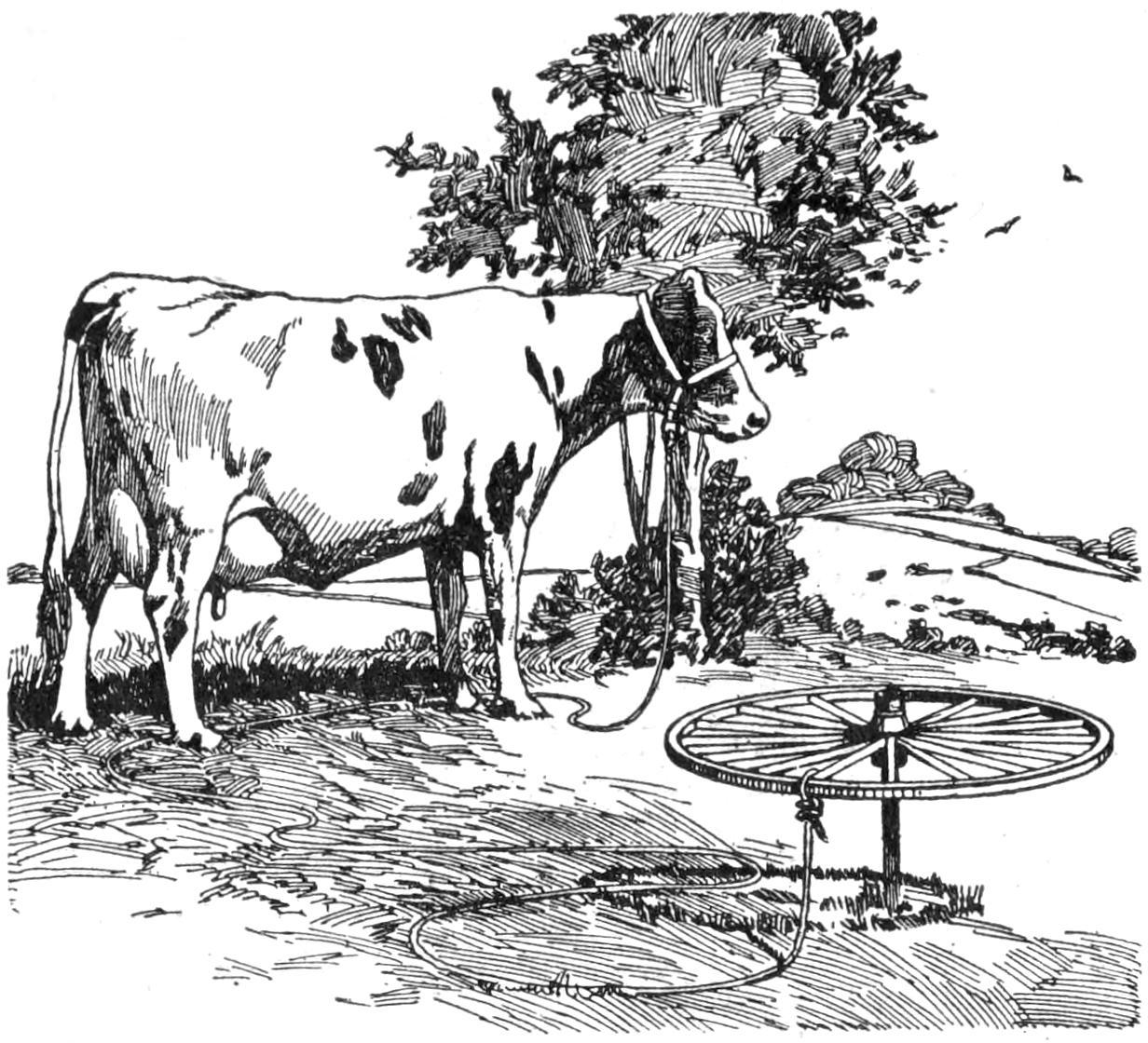
The Wheel Revolves on the Stake, Preventing the Rope from Tangling
An old carriage wheel and axle were used to good advantage in the making of the pasture stake shown in the sketch. When the animal tethered to the wheel walks around the stake, it is practically impossible for the rope to become tangled, as the wheel revolves on the axle.—Contributed by W. F. Quackenbush, New York, N. Y.
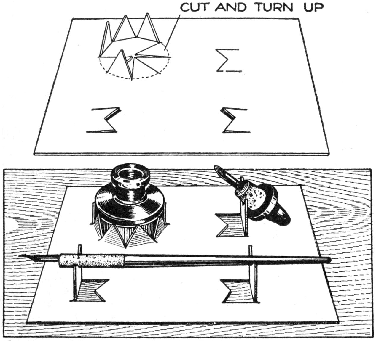
A Sheet of Heavy Paper Quickly Transformed into a Holder for Ink Bottle and Pen
Drawings are not infrequently ruined by the spilling of ink, which might have been averted by the use of the simple inkstand cut from a sheet of heavy paper, as shown in the sketch. The upper illustration shows the method of cutting the paper to fit the ink bottle and stopper, and to produce a pen rack. The device will be found especially useful when materials for drawing are used away from a place especially fitted for the purpose, since the inkstand can be made in a few minutes from material readily available.—Contributed by Henry C. Franke, Jr., Philadelphia, Pa.
When a beginner, it was the despair of the writer to try to produce in his homemade apparatus the mathematical regularity and perfection of the winding on the coils of electrical instruments in the supply stores, but when he found that this professional and workmanlike finish could be obtained by means of a simple contrivance, and a little care and attention to details before beginning, experimental work took on a new interest.
At the outset let it be stated that wire should never be wound directly on the iron core, not only because it cannot be done satisfactorily in that manner, but for the reason that it is often desired to remove a coil from a piece of apparatus after it has served its purpose. It is therefore advisable to make a bobbin, which consists of a thin, hard tube with two ends. The tube may be easily formed by wrapping a suitable length of medium-weight paper on the core, having first coated it with ordinary fish glue, excepting, of course, the first 2 or 3 in. in direct contact with the core. Wind tightly until the thickness is from ¹⁄₃₂ in. to ¹⁄₁₆ in., depending upon the diameter of the core, and then wrap with string until the glue hardens, after which the tube may be sandpapered and trimmed up as desired.
Where the wire is not of too small a gauge and is not to be wound to too great a depth, no ends will be necessary if each layer of wire is stopped one-half turn before the preceding one, as indicated in the accompanying[137] sketch, and is also thoroughly shellacked. With ordinary care magnet wire may be wound in this manner to a depth of over one-half inch.
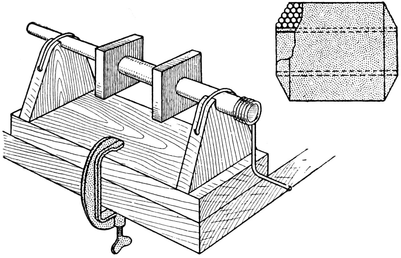
Winding a Coil of Wire so That the Layers will be Even and Smooth
The tube having been made ready, with or without ends as may be necessary, the small winding jig illustrated is to be made. All that is essential is to provide a suitable means for rotating by hand a slightly tapering wood spindle, upon which the tube is to be pushed. The bearings can be just notches made in the upper ends of two standards, through each of which a hole is drilled at right angles to the length of the spindle, so that some string or wire may be laced through in order to hold the spindle down. A crank may be formed by winding a piece of heavy wire around the larger end of the spindle. A loop of wire, or string, is to be attached at some convenient point, so that the crank may be held from unwinding while adjusting matters at the end of each layer, or while making a connection. There should also be provided a suitable support for the spool of wire, which is generally placed below the table to good advantage. Much depends, in this sort of work, upon attention to these small details, after which it will be found that the actual winding will require very little time.—Contributed by John D. Adams, Phoenix, Ariz.
¶A No. 10 gauge shotgun cartridge shell telescoped with a No. 12 gauge shell forms a convenient match safe for campers, or other persons out of doors, and is moisture-proof.
Two oblong peach baskets, their bottoms fastened together and the whole covered with silk, formed the hourglass sewing or darning basket shown in the sketch. Square plum baskets and other forms trimmed in cretonne, linen, or inexpensive goods, depending on the intended use, may also be utilized. Ornamental details may be added to suit the individual taste.
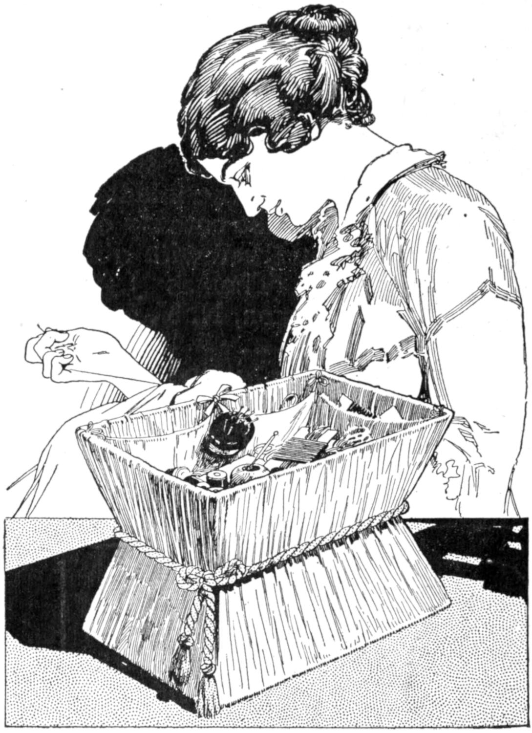
Artistic Effects may be Produced by the Inventive Woman
The basket was made as follows: The peach baskets were wired together at their bottoms. A piece of silk was cut, wide enough to reach from the top to the bottom of the joined baskets and to permit the folding over of a portion at the top and bottom. One long edge of the piece was glued to the inner edge of the bottom and drawn in around the sides to form neat folds. The upper edge of the silk was then glued in the top, being folded over the edge.
A cord was fixed around the middle of the basket, as shown in the sketch.[138] A lining was glued into the top and bottom. It was folded and stitched along its edges to prevent raveling and to give a smooth finish. The bottom need not be lined, but it is desirable to have it so.
The pincushion was made by padding a block with cotton and then covering it with silk. A cardboard box may be used instead. The cushion was nailed into place from the bottom. Ribbon may be used to draw the silk to the sides of the basket at the middle, and a cushion may be made entirely of cotton or cloth and attached with ribbons.—Contributed by Thomas J. Macgowan, Mount Vernon, N. Y.
The fallacy of perpetual motion is now so generally understood that the description of a new scheme for attaining it is only justified in so far as it may be instructive. The sketch illustrates such a device, apparently successful, and the discovery of the error in it is both instructive and interesting.
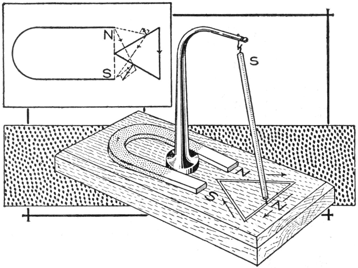
The Interaction between Poles of the Magnets Causes the Traveler to Move around the Triangle
Mount a horseshoe magnet on a wooden base, and into the latter cut a continuous groove along the three sides of a triangle opposite the poles of the magnet, N and S. Suspend a long, narrow bar magnet on a universal joint from a standard. A pin projects into the groove from the lower end, which is its north pole, and can move only along the triangular course.
Start the device with the suspended magnet in the position shown. The lower end will tend to move in the direction of the arrows, because in so doing it is getting farther away from the repelling north pole of the horseshoe magnet and nearer the attracting south pole, which action will bring it to the corner of the triangle in the foreground. It will next move down the side as indicated by the arrow, because along that line it is nearer the attracting south than the repelling north pole. When it reaches the end of its trip, at the angle between the poles of the magnet, the attraction and repulsion will be balanced, but a slight jar will carry the traveler beyond the angle.
The third leg of the triangle will be covered similarly, the north pole repelling the traveler. On this basis the motion should continue indefinitely, but a test will show that it will not do so.
The corners of the triangle should be rounded slightly and it would be better to use several hanging magnets, flexibly connected, so that when one is at the dead center the others will carry the traveler on.
Soiling of drawings transferred with carbon paper may be avoided by substituting a piece of unfinished paper, the surface of which has been covered with a thin coating of lead rubbed from the pencil. If any errors are made in the tracing, or undue pressure is applied with the hand, the resulting impressions may be removed readily with an eraser.
If a copy of a drawing is desired, and it is not necessary that the same relative left and right position be maintained, the original pencil drawing may be placed face downward on a sheet of paper and the back of it rubbed with a bone paper knife, or other smooth, rounded object. By going over the impression and making a reverse of it in the same way a copy of the original in the same relations may be obtained.—Contributed by J. E. Pouliot, Ottawa, Canada.
[139]

Both as a safety device and a practical novelty, a homemade searchlight for a canoe, or other small craft, is worth while making. An old milk strainer was used for the reflector of that shown, and many equally serviceable makeshifts can be devised easily from old cans, or formed from sheet metal. The detailed construction, as indicated, is suggestive only, since local conditions and materials available will govern the design of the fittings. The light has a double control, one cord governing the vertical adjustment, and another, arranged like that of a ship’s wheel, the horizontal pivotal range. The vertical adjustment is desirable, but not essential. The control cords are run in screw eyes along the coaming of the craft, so that one person can paddle the canoe, and adjust the searchlight as well. Dry cells, stored under the bow deck, or in a box set at some other convenient place, supply the current for the 6-volt lamp.
Canoeing and Boating at Night Is Safer and More Pleasurable if the Craft is Equipped with a Searchlight. This One was Made of Pick-Up Materials at Small Cost
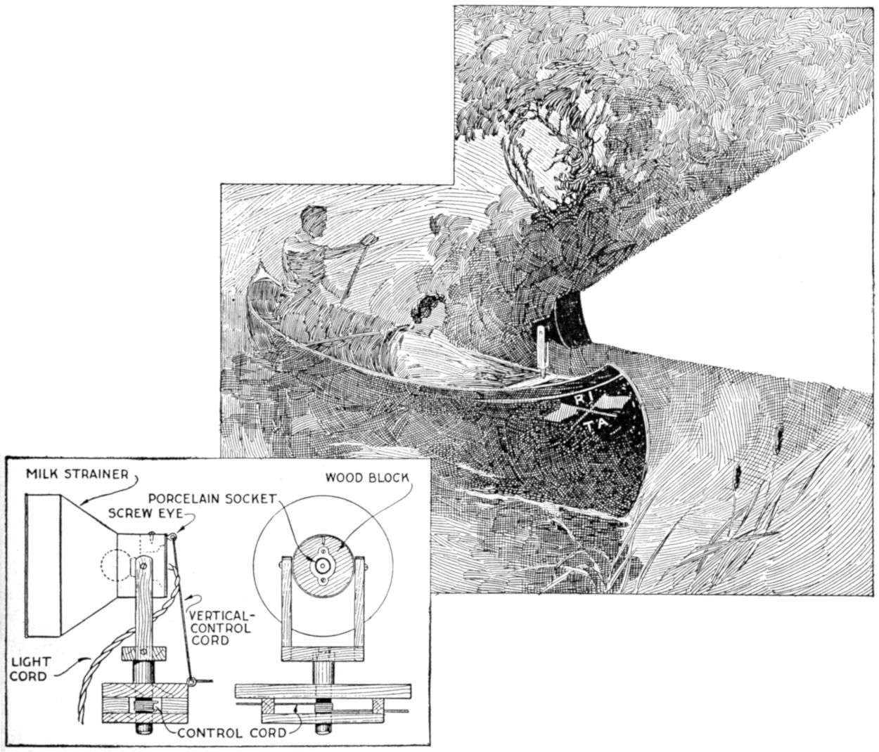
The Support for the Reflector is Pivoted in the Deck, Reinforced as Indicated
The main dimensions of the fittings, as detailed, are: strainer, 10 in. in diameter and 10 in. long; vertical support, 12¹⁄₂ in. over all, and 6 in. wide at the upper portion; the wood used is ¹⁄₂ and ³⁄₄ in. thick, except that for the pivot post, which is 1 in. thick. The reflector is fitted with a wooden block through which the porcelain socket is set, as shown. A knife switch,[140] placed near the stern of the craft, controls the connection with the battery circuit.
The inside of the reflector should be polished with emery cloth, and if the surface is rough, it may be painted with white enamel. The outer surfaces of the metal part are painted black. The wooden parts may be painted, or given several coats of spar varnish, to withstand the weather.
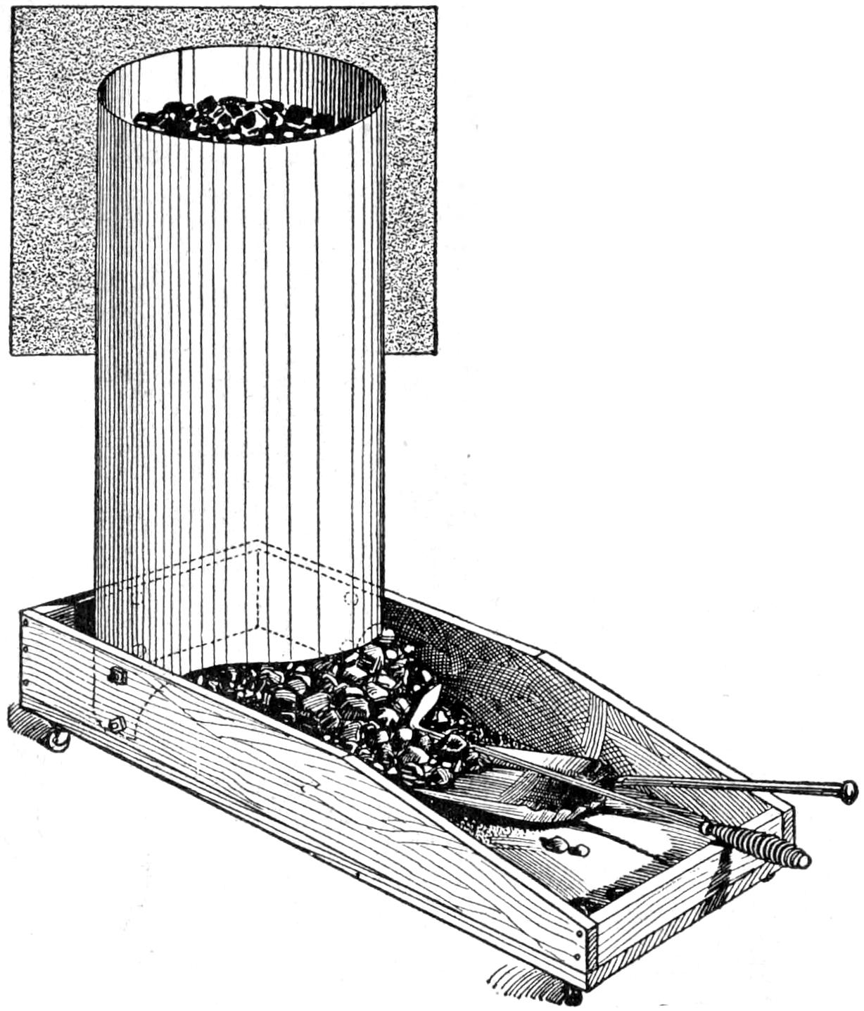
The Large Capacity of the Hopper and the Ready Portability of This Arrangement Are Practical Features
In the large farm kitchen, in the workshop, and even for firing a small furnace, a coal hopper that will hold considerable coal, and that can be rolled along the floor easily, is a convenience. Such an arrangement, made from a section of galvanized-iron pipe, 10 in. in diameter and 30 in. long is shown in the sketch. The pipe was cut at one end, as shown, so that when the coal was poured into the hopper, it would feed out. A truck, mounted on casters, was made, 12 in. wide, 5 in. high, and 25 in. long. The hopper was mounted on one end of it, and bolted securely at the sides and end. The coal is shoveled into the hopper at the bin, and the load pushed to the furnace, where it can be easily used as needed. The construction can be made larger for use with a coal scoop, in firing a boiler or large furnace.—L. R. Markwood, Factoryville, Pa.
Falling snowflakes in a camera photograph—the large feathery, slow falling kind—often make an exquisitely beautiful picture out of a commonplace scene. And while the great majority of the attempts to get them prove failures, the photographer—usually an amateur-needs only to provide an avenue in front of his lens a short distance, that is free from falling flakes by the use of a shelter such as a tree or porch. The slow snapshot necessary in cloudy weather will not stop the motion of the flakes nearest the camera and these passing through greater angles of space in equal length of time than those farther away, will blur on the negative. We made some excellent outdoor views in deep snow, while heavy snow was falling, with flakes splendidly decorating the darker regions of figures and foliage, by holding a felt hat and two umbrellas in a line in front of the camera, and above the range of the lens.—J. Cecil Alter, Cheyenne, Wyo.
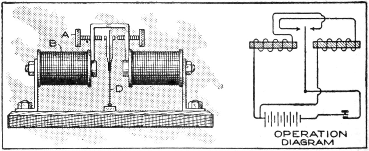
When the Vibrator Touches One Contact, the Coil on the Opposite Side Attracts the Vibrator, This Process being Repeated Alternately
A double-contact vibrator, which eliminates sticking contacts, spring troubles, and other sources of annoyance, in addition to producing a fine high tone, is shown in the sketch. It is an instrument easy to construct, by reason of its simplicity. Special care in making the vibrator D will insure good vibration. The springs, holding the contacts, are of phosphor bronze The contacts may be made of silver platinum, or other metals, which will not burn and break contact. The coil[141] B are of the common bell-ringing type. The springs on the vibrator should not be too long, nor too weak; experimenting will determine the length at which they will work best. The adjustment is made at the thumbscrews A. The coils are supported on metal brackets, bolted to a wooden base. The method of hooking up the vibrator in the key circuit is shown in the diagram.—J. L. Taylor, Barker, N. Y.
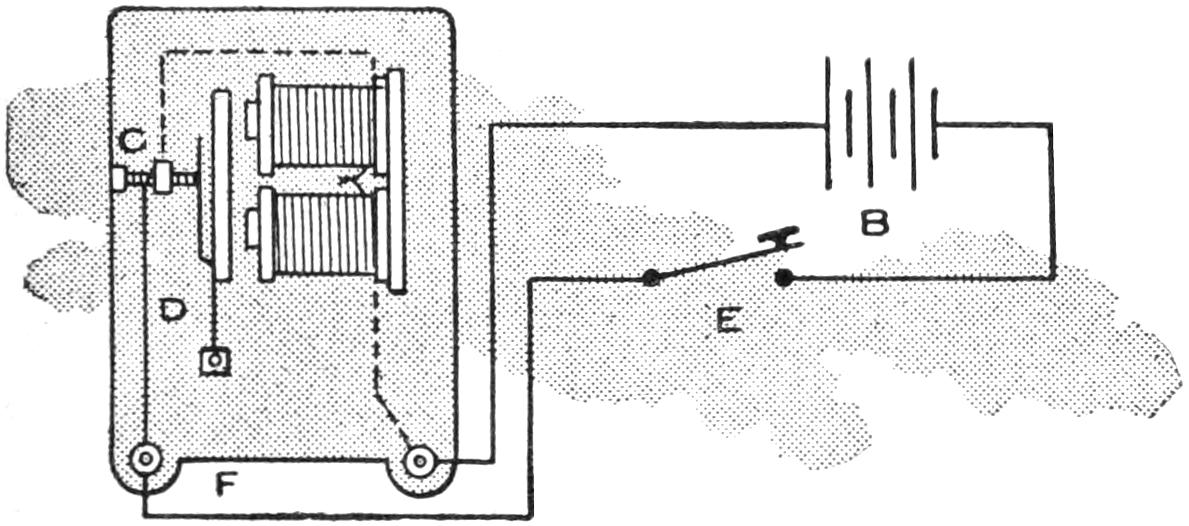
The Amateur can Practice the Morse Code Handily on This Sounder, Made from a Buzzer
An ordinary battery buzzer may readily be converted into a telegraph sounder for use in practicing the Morse code. All that is necessary is to connect the vibrator contact C of the buzzer to the binding post that is not insulated from the frame. The other connections of the key and battery are the same as in any ordinary telegraph or buzzer circuit. In the diagram, C represents the vibrator contact; D, the wire connecting the contact and the uninsulated binding post, and F, the uninsulated binding post; E is the telegraph key, and B, the dry cells.—Clarence F. Kramer, Lebanon, Ind.
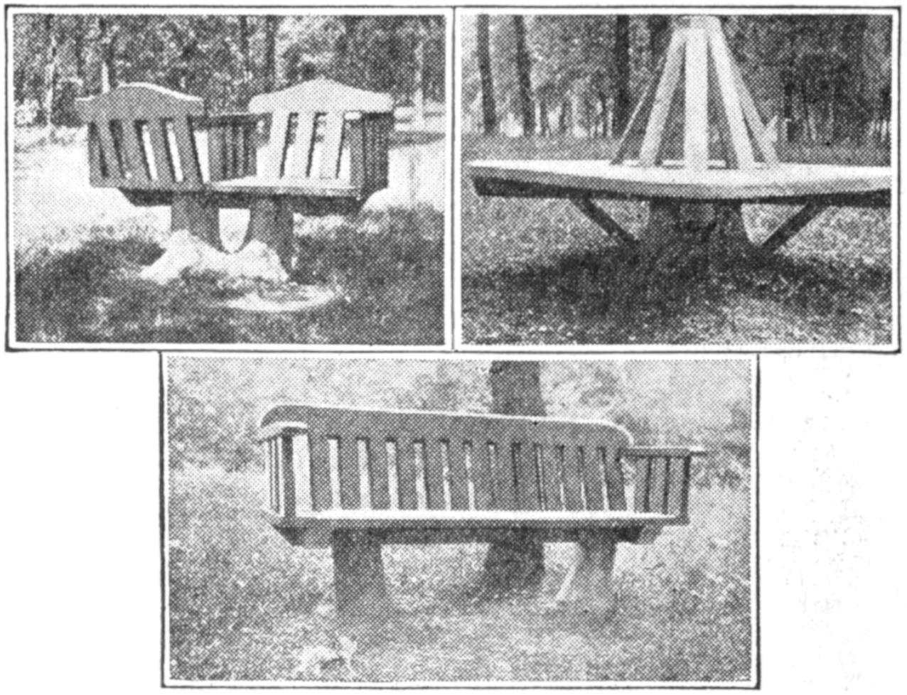
These Practical Lawn Seats Show the Possibilities of Stumps as Supports for This Purpose. The Conservation-Chair Design Is Especially Interesting
A practical use to which stumps, left from the felling of trees, are put in a city park is as supports for lawn benches. This obviates the need of grubbing them out, while the work of preparing them to receive the seats is less than would be required to remove the stumps. Of course, the location of the stump will determine whether it is worth while as a support for a seat, or had better be grubbed out. Many designs are possible, and the position and size of the stumps available will suggest suitable construction. The woodwork for the seats is simple, and the benches can be made removable for the winter if desired.—C. L. Meller, Fargo, N. D.
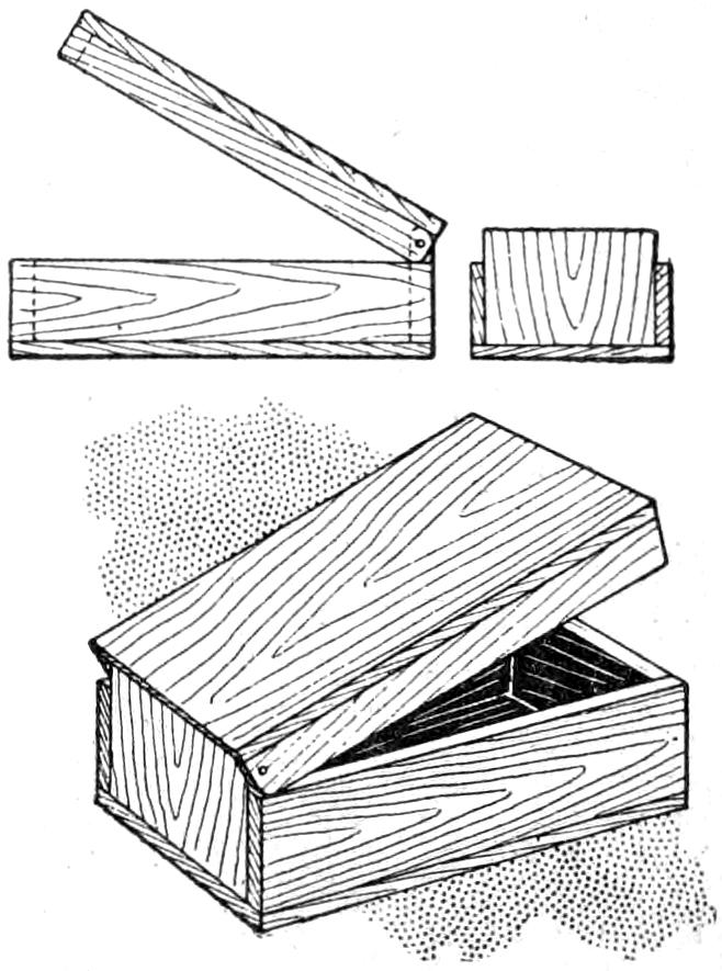
When a wooden box with a hinged cover is desired, especially a small one, hinges are not always at hand, and are sometimes difficult to obtain. Under these circumstances a good substitute is to make the box as shown in the sketch, using the extension of one end and nails, or screws, driven through the back corners of the lid, as a hinge arrangement. This makes the use of hinges unnecessary, and is serviceable even for permanent use. Where hinges projecting from the surface of the box are objectionable, this method of construction is especially desirable. It is best to make the hinged ends with the grain vertical, and to round off the hinged corners of the lid slightly.—R. J. Rohn, Chicago, Ill.
[142]
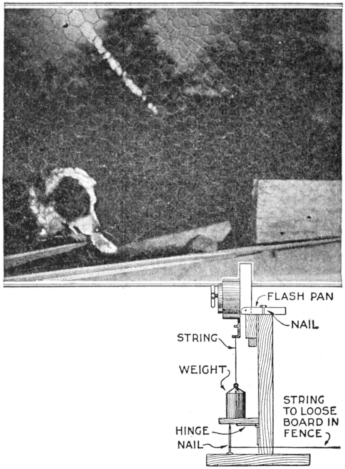
This Photographic Evidence Was Proof Positive as to the Identity of the Thief in the Night
After the wire fence around the chicken house had been torn up, and the place entered 13 nights in two weeks, I decided on more preparedness. Various ways and means failed, so I used a comparatively slight knowledge of photography in the process.
I mounted my flash lamp on a piece of board, 1 by 4 by 8 in. long, and fastened this to a base, as shown. I attached a weight to the lamp, which was supported by a hinged drop, halfway down the upright board, which in turn was supported by a nail, to which was attached a string. The flash was set off by a slight pull of the string, which dropped the weight. This contrivance I concealed in the chicken yard, and the camera in the chicken house. That night I opened the lens of the camera in the dark, and attached the string to a loose board in the fence. The next morning, before daybreak, I closed the lens again. The flash had been set off during the night. Also there were drops of blood on the ground. I could hardly wait until the plate was developed. The result, as reproduced, was hardly what I expected.—H. U. Scholz, Medford, Ore.
At the camp or on the trail, an emergency fishing-tackle outfit is almost as handy as matches, compass, and knife, and it may even be the means of saving one’s life. A convenient way to carry such an outfit is in two old shotgun shells, telescoped. The hooks, on a cork, and the sinkers are fitted snugly into the shell. Several yards of line are then wound on the outside. This outfit can be stowed into a pocket handily, always ready for use.—E. Everett Buchanan, Jr., Elmira, N. Y.
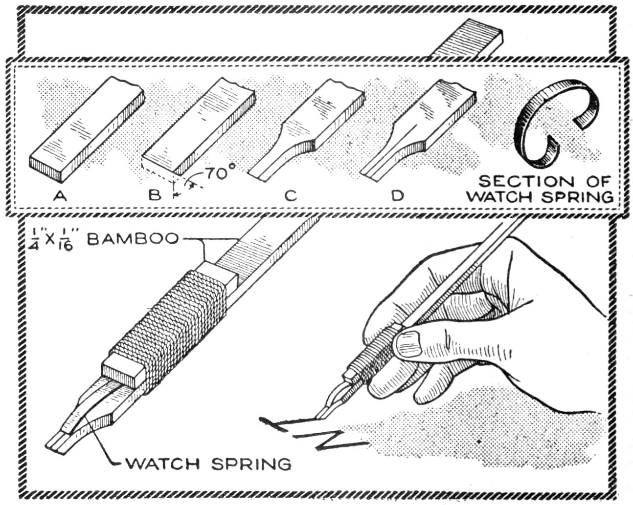
This Pen, Cut from a Piece of Bamboo and Fitted with a Spring Fountain Device, Is Especially Useful for Marking Packages
Marking of packages and similar lettering can be done neatly with a pen made in a few minutes from split bamboo fitted with a short section of watch spring. Select a piece of bamboo, ¹⁄₄ by ¹⁄₁₆ in. and about 7 in. long, and finish the end, as at A. Trim the end to an angle, as at B, and then point it, as at C. Split the point carefully, as at D, and smooth away the tufts at the edges. Cut a piece of watch spring the width of the pen point and bind it into place, arched as shown. To use the pen, insert ink into the arch of the spring, and it will work much like a fountain pen.—Raymond H. Lufkin, Dorchester, Mass.
[143]

The houseboat shown is of the scow design, 6 ft. wide by 20 ft. long, with the cabin extending beyond the scow 1 ft. on each side. The scow tapers up at the forward end and is protected with a heavy sheet-iron plate so that the craft may be snubbed up on sandbars without danger of springing a leak, even though a submerged log be struck while running at full speed.
The power plant consists of a standard 4-hp. reversing gasoline engine which drives the paddles at their most efficient speed, 45 revolutions per minute through a 13-to-1 reduction. Cast-iron hubs, into which are inserted cold-rolled steel spokes, and wood paddles bolted to their ends constitute the propeller wheels. The cruising speed is about 4 miles an hour.
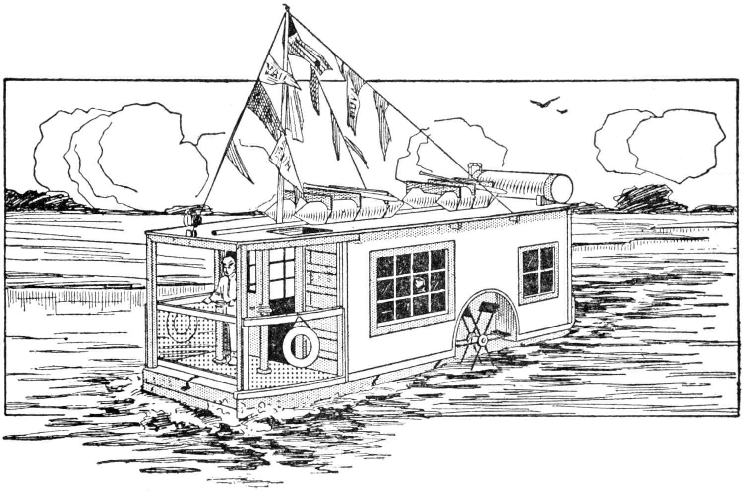
The Hull of the Houseboat is Built on the Scow Type so That It can be Run in Shallow Water without Danger
Two wide bunks, beneath which is locker space, provide sleeping accommodations for a crew of four. In the kitchen the motor and gearing are almost completely concealed under the work table. The cooking is done on a two-burner blue-flame kerosene stove, and the sink is provided with running water suitable for washing dishes, etc. This water is drawn from a 30-gal. tank on the roof, which is filled by a centrifugal pump driven from the engine shaft. A modern toilet room is installed, and an ice chest on the after deck will hold supplies and ice for a week’s cruise.

Detail of the Anchor Windlass and Engine Gearing; Also the Deck Plan, Showing the Location of the Parts and the Arrangement of the Cabins
An acetylene-gas lighting system is installed and is used to light both cabins and a searchlight. A heavy anchor of special design is manipulated by a windlass on the forward deck. A[144] similar device controls the rudder. Life rafts, complete with paddles, are placed on the roof, and in hot weather these are moved to one end and an awning erected to make a cool sleeping place.
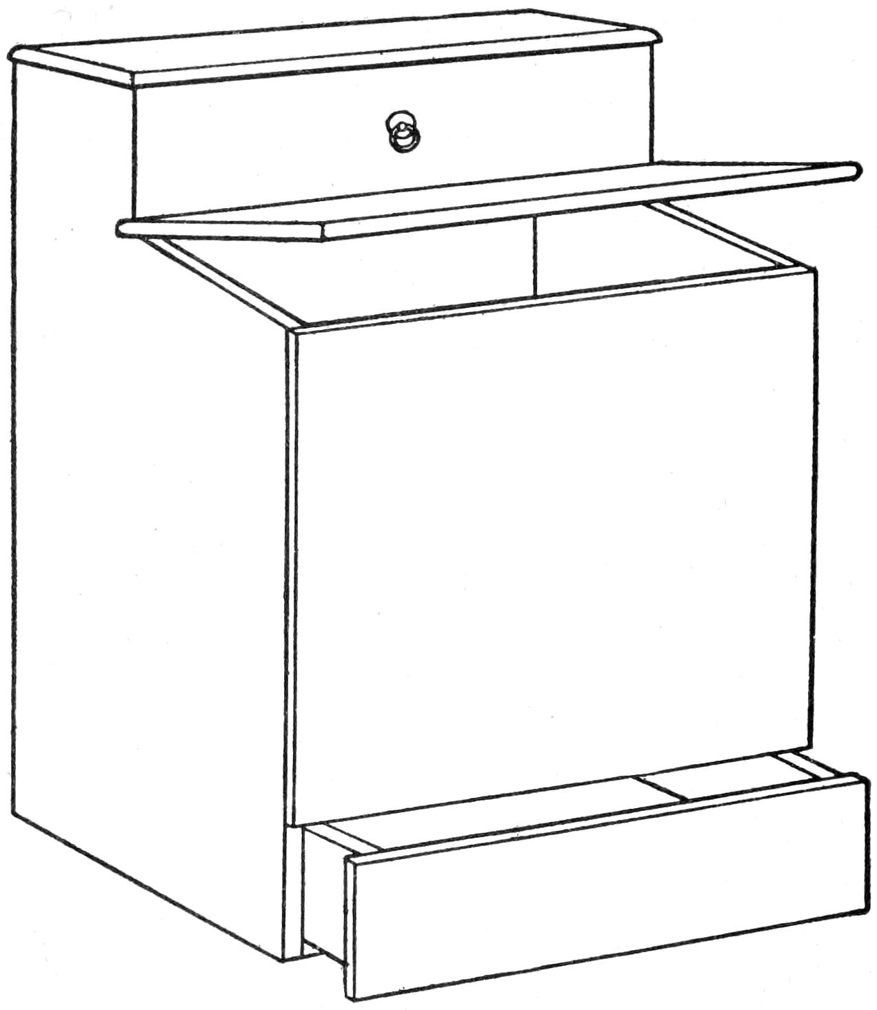
The Wood Receptacle Has a Drawer Bottom for Catching the Dirt, Which can be Easily Cleaned
The ordinary wood box may be greatly improved by adding a drawer at the top and one at the bottom, as shown in the sketch. The upper drawer is used for storing the flatirons and stove-polishing materials, and the lower drawer is the bottom of the wood box. The dirt and pieces falling from the wood remain in the drawer, which can be removed and cleaned easily.—Contributed by William Jutila, Astoria, Ore.
To make a quarter disappear from a glass of water after hearing it drop is a very puzzling trick. The articles necessary to perform this trick are a glass of water, a handkerchief, a quarter and a piece of clear glass the exact size of a quarter. The glass can be cut and ground round on an emery wheel, and the edge polished.
To perform the trick advance with the piece of glass hidden between the second and third fingers of the left hand and holding the quarter in plain sight between the thumb and first finger of the same hand and the handkerchief in the right hand. Throw the handkerchief over the left hand and gather up the glass piece in the fold of the cloth, allowing the coin to drop into the palm of the left hand while covered. Remove the left hand and hold out the piece of glass with the handkerchief drawn tightly around it. Anyone can touch the cloth-covered glass, but it cannot be distinguished from the quarter. While this is being shown slip the quarter into a pocket. Spread the handkerchief over the glass of water and allow the glass disk to drop. A distinct click will be heard when it strikes the bottom. Raise the handkerchief and nothing will be seen, as the glass will not be visible in the water.—Contributed by Amon H. Carr, Gainesville, Tex.
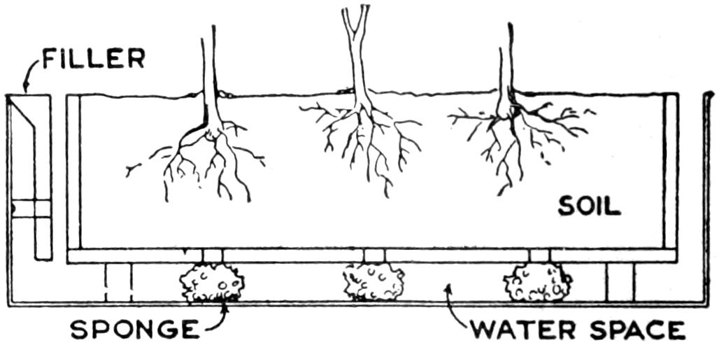
The Soil is Kept Moist by the Water Feeding through the Sponges from the Under Side
The window box for flowers can be conveniently watered in the following manner: Construct a metal box to receive the box holding the soil and bore enough holes in its bottom to admit water to the soil. The inside box should be supported about 2 in. above the bottom of the metal box. Sponges are placed in the bottom to coincide with the holes in the soil box. A filling tube is made at the end. The water is poured into the metal box and the sponges admit only enough water for the plants at all times.
[145]

Dragon kites are made as hideous as the maker can possibly conceive, and while the one to be considered is no beauty, it is more droll than fierce-looking. In general appearance the dragon and centipede kites are like huge caterpillars floating about in the air. The kite sometimes twists and the balancer sticks appear to be large hairy spines. Usually the tail end swings higher than the head. It is like so many single kites, pulls hard, and requires a strong cord for the line. The individual circular sections may number 20, and if placed 30 in. apart, would make a kite about 50 ft. in length, or the number of sections may be more or less to make it longer or shorter. The kite will fold up into a very small space, for carrying about or for storage, but care should be taken in folding not to entangle the harness.
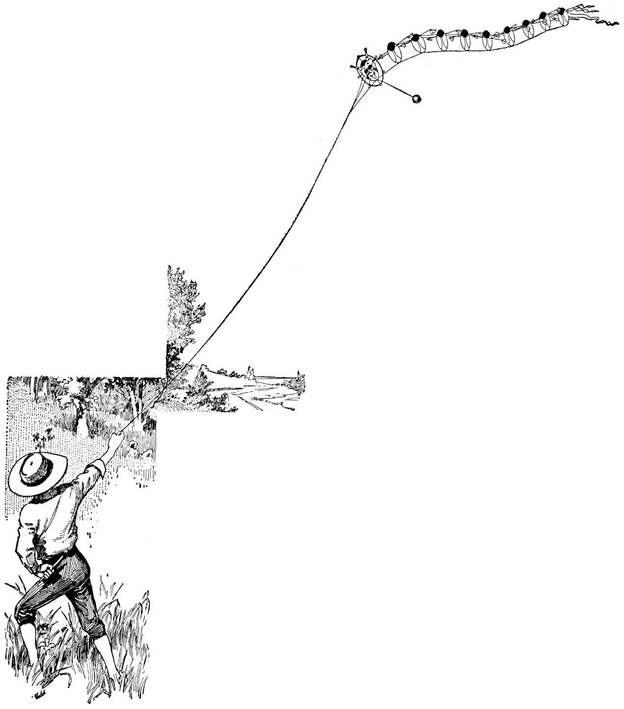
In General Appearance the Dragon Kite Is Like a Huge Caterpillar Floating About in the Air
The head requires much more work than any of the other sections. There are two principal rings to this section, as shown in Fig. 1. The inner ring is the more important, the outer one being added for the protection of the points when alighting. The construction of the framework is shown in Fig. 2. It is made entirely of bamboo. The bamboo is split into strips, about ³⁄₁₆ in. wide, for the ring A. As the bamboo strips will be much too thick, they must be pared down to less than ¹⁄₁₆ in. The diameter of the ring A is 12 in., and a strip of bamboo to make this ring should be about 38 in. long, so that there will be some end for making a lap joint. The ends of the strip are held securely together by winding them with linen thread. The Chinese boys use strips of rice paper, about ¹⁄₂ in. wide and torn lengthwise of the paper. The rice-paper strips are made wet with paste before winding them on the joint, and when they dry out the shrinkage will bind the ends securely.
Two crosspieces, of the same weight as the ring stick, are placed 3¹⁄₂ in. apart, at equal distances from the center and parallel, as shown at B and C. The ends of these pieces are turned at a sharp angle and lashed to the inside surface of the ring A. To make these bends, heat the bamboo over a candle flame until it will give under pressure, then bend and it will stay in shape after it becomes cold. This method of bending should be remembered, as it is useful in making all kinds of kites. Two[146] small rings, each 3¹⁄₂ in. in diameter, are put in between the two parallel pieces, as shown at D and E. These are for the eyes of the dragon. The rings are lashed to the two crosspieces B and C. As the eyes revolve in the rings they should be made perfectly true. This can be done by shaping the bamboo about a perfectly round cylinder, 3¹⁄₂ in. in diameter. To stiffen the whole framework, two pieces of bamboo, ¹⁄₁₆ in. thick, ¹⁄₈ in. wide, and 20 in. long, are lashed to the back as shown by F and G. There is a space of 3 in. between the inner ring A and the outer ring H, giving the latter a diameter of 18 in. It is made of a bamboo strip, ¹⁄₈ in. wide, and should be less than ¹⁄₁₆ in. thick. It may be necessary to make this large ring from two pieces of bamboo, to get the length, and in such case be careful to make a perfect ring with the ends well lashed together. Two short pieces are lashed to the two rings, as shown at J and K. The supports for the horns consist of two pieces, ¹⁄₈ in. wide and less than ¹⁄₁₆ in. thick, and they are lashed to the upper crosspiece and to both rings, so that the parts L and M are exactly halfway between the ends of the pieces F and G and radiate out from the center of the ring A, the other parts, N and O, pointing to the center of the eye rings, respectively. The ears are unimportant and may be put on if desired. The rings on the horns and the stick ends may be from ¹⁄₂ to 2 in. in diameter, cut from stiff paper, but if larger, made of bamboo.
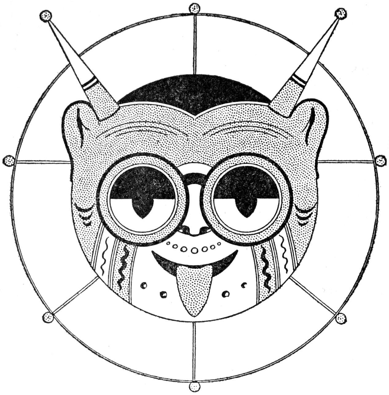
Fig. 1
The Kite-Head Section, Having Horns, Ears, and
Revolving Eyes, Is Very Hideous
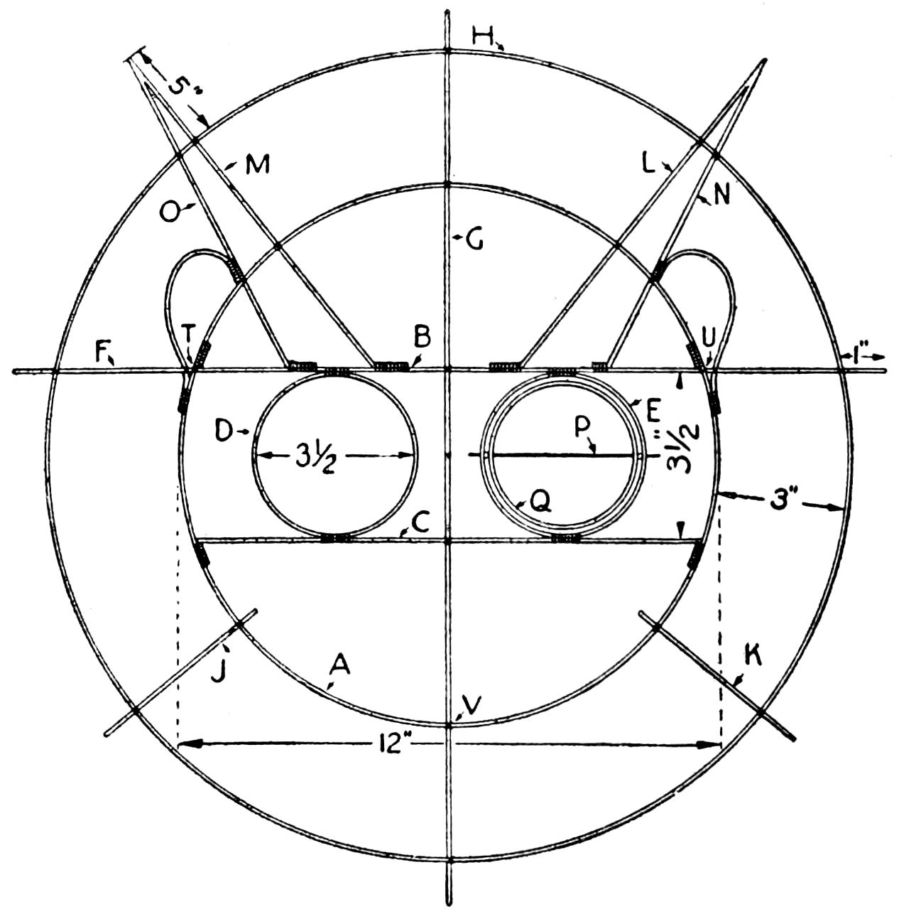
Fig. 2
The Framework for the Head Section is Made
Entirely of Bamboo Strips Lashed at the Joints
Chinese rice paper is the best material for covering, and it should be stretched tightly so that there will be no buckling or bagging places. The only part covered is that inside of the inner ring A, the horns, and the ears, leaving the eye rings open. The shades are put on with a brush and water colors, leaving the face white, or it can be tinted in brilliant colors. Leave the horns white and color the tongue red.
The frame for each eye is made of bamboo, pared down to ¹⁄₃₂ in. in thickness and formed into a perfect ring, 3¹⁄₄ in. in diameter. Each ring revolves on an axle made of wire passed through the bamboo exactly on the diameter, as shown at P, Fig. 3. The wire should be long enough to pass through the socket ring D or E, Fig. 2, also, and after the eye ring is in place in the socket ring and the axle adjusted, the latter is fastened to the eye ring with a strip of paper wrapped tightly around the wire and pasted to the bamboo of[147] the ring. A glass bead, placed on the wire axle between the socket rings D or E and the eye ring Q on each side, keeps them apart and the revolving one from striking the other.
Each side of the eye ring is covered halfway with rice paper, as shown in Fig. 4. The part R is on the upper front half, and that shown by S is on the back lower half. Placing the two halves in this manner causes an unequal pressure of the wind on the whole eyepiece, and thus causes it to revolve on the axle. The front upper half of the eyepiece is made black, and the smaller dark portion extending below the darkened half is a round piece of paper placed just between the two halves so that half of it will show on both front and back of the eyepiece. When the eyepiece is given a half turn in its socket the back side will come to the front and will appear just the same as the other side. Some kite builders add pieces of mirror glass to the eyes, to reflect the light and cause flashes as the eyes revolve in their sockets.
The ring for the section kite is made the same size as the inner ring of the head kite, or in this case 12 in. in diameter. The bamboo for making this ring should be ¹⁄₈ in. wide and ¹⁄₁₆ in. thick. The balancer stick, 36 in. long, is located about the same place as the cross-stick F, as shown in Fig. 2, and must be made small, light and well balanced. Small tufts of tissue paper, or feathers, are attached to the tip ends of the balancer sticks, as shown in Fig. 5. The cover for the section kite is put on tightly, the same as for the head, the colors indicated in the sketch being only suggestions, as the builder can color them as desired. The balancer on the last section should have streamers, as shown in Fig. 6, for a finish. The streamers are made of light cloth.
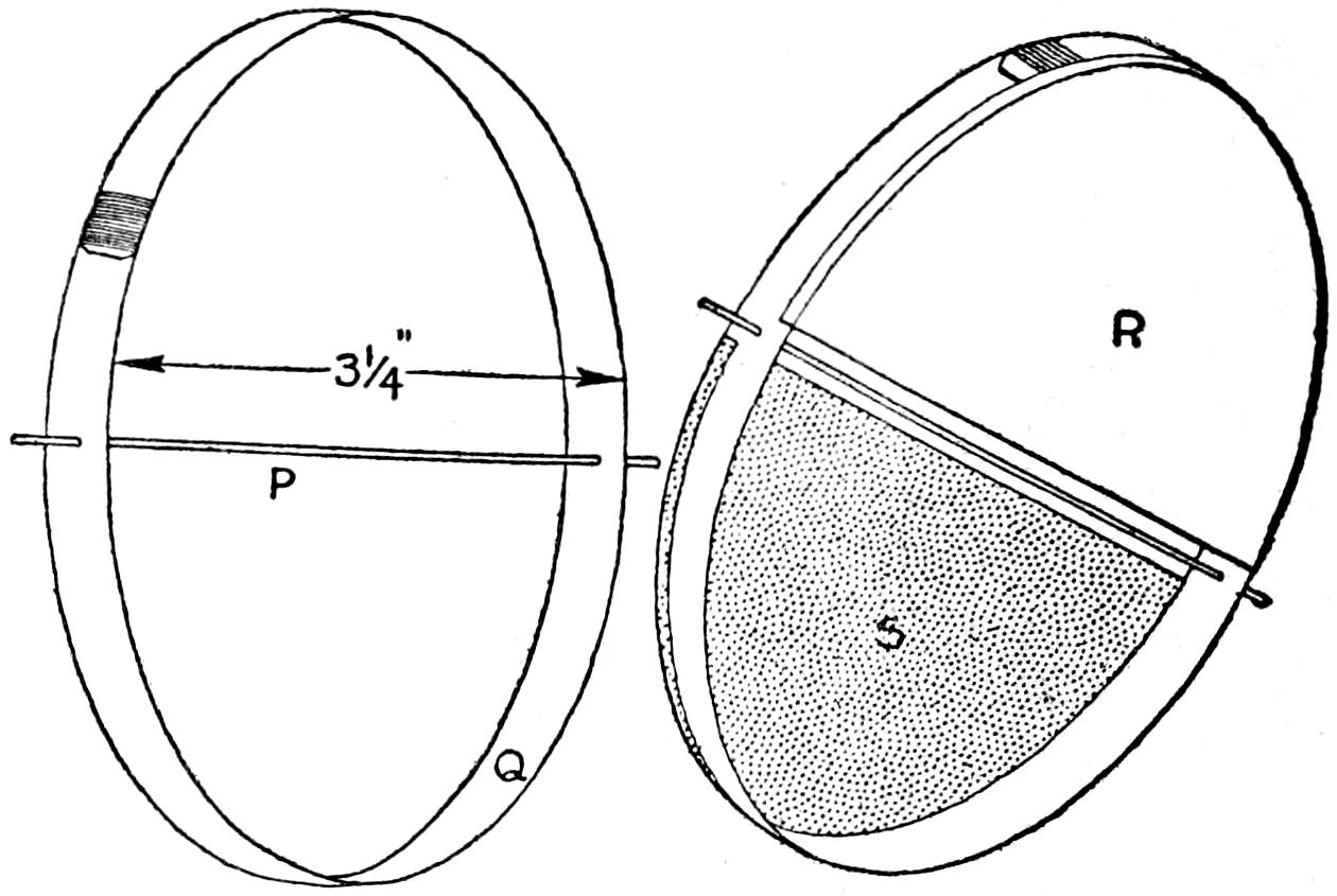
Fig. 3
Fig. 4
Two Bamboo Rings with Paper Coverings, to Make Them Turn in the Wind, Constitute the Eyes
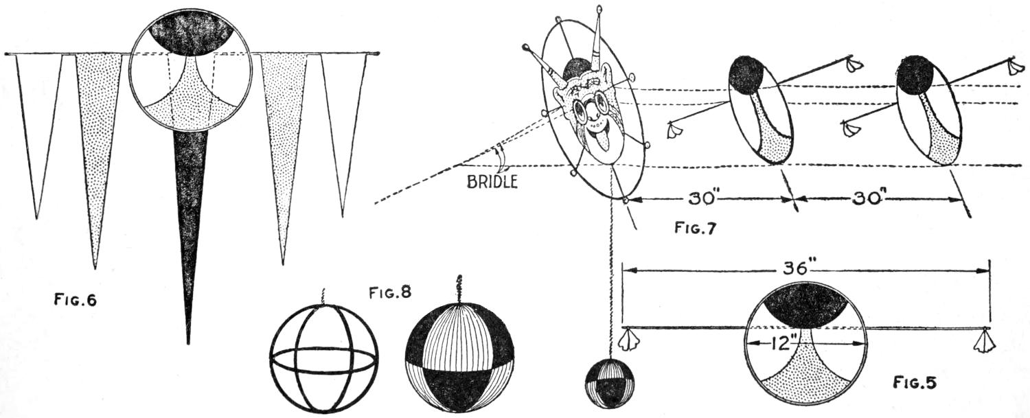
| Fig. 6 | Fig. 7 | ||
| Fig. 8 | Fig. 5 | ||
The Section Kites Have Balancers and the Disks are Given Bright Colors So That They will Produce the Effect of a Great Dragon When in the Air, the Head Piece Having a Ball Balancer Hanging from the Under Edge
As previously stated, 20, more or less, sections can be used, and the number means so many separate kites which are joined together with three long cords, spacing the sections 30 in. apart. The cords should be as long as the kite from the head to the tail, allowing sufficient[148] extra length for the knots. As such a kite will make a hard pull, the cord used should be a six-ply, hard-twisted seine twine. Start by tying the three long cords to the head kite at the points T, U, and V, Fig. 2. Tie the next section at corresponding places just 30 in. from the head kite. The construction will be much easier if the head kite is fastened to a wall so that each cord may be drawn out to its proper length. Continue the tying until all sections are attached just 30 in. apart. Other spacing can be used, but the distance selected must be uniform throughout the length of the kite. The individual kites, or sections, may vary in size, or they can all be 9 in. in diameter, instead of 12 in., and the balancer sticks 30 in. long instead of 36 in., but a kite of uniform sections is much better and is easier to make. The positions of the sections as they will appear in the kite are shown in Fig. 7.
The Chinese bridle is usually made of three strings, which are attached to the same points on the head kite as the harness cords, or at T, U, and V. The lower string is longer than the two upper ones so that the proper inclination will be presented to the breeze. As the head is inclined, all the section kites will also be inclined. Some makers prefer a balancer on the head kite, and in one instance such a balancer was made in the shape of a ball. A ball made of bamboo strips is shown in Fig. 8, and is attached as shown in Fig. 7.
It will be necessary to have a helper, and perhaps two, in starting the kite up, as the harness might become entangled. Quite a little run will be necessary, but when up the kite will make a steady flier and will pull very hard. If the first attempt is unsuccessful, try readjustment of the bridle or a little different position in the breeze, and see that the balancers are not tangled. Quite a number of changes may be worked out on these plans, but it is necessary to bear in mind that the distances between sections must be equal and that the general construction must be maintained.
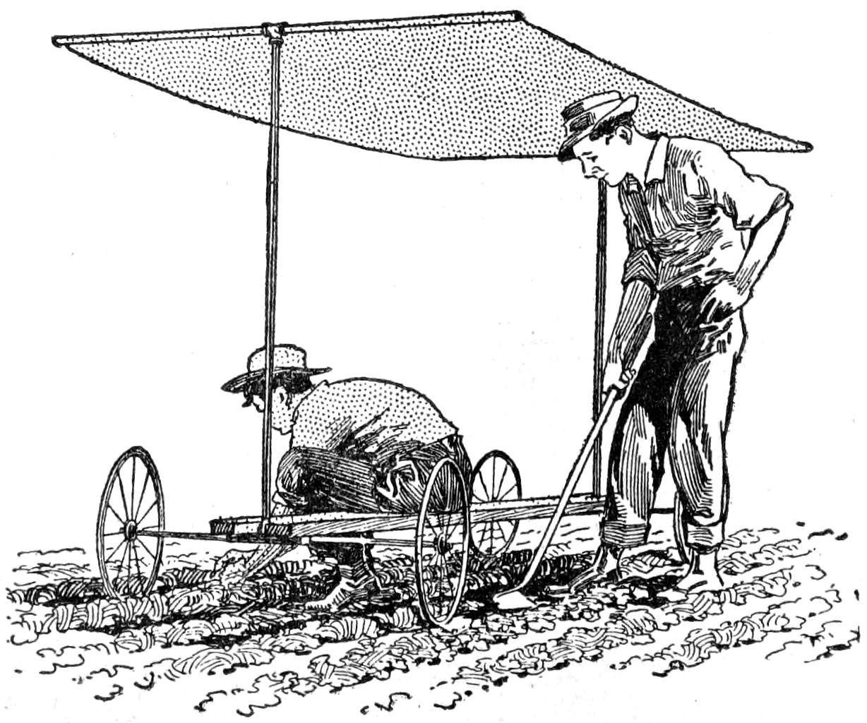
The Sunshade and Seat are Mounted on Wheels So That the Device can be Easily Moved About
Weeding gardens under a hot sun and in a necessarily uncomfortable position is by no means a pleasant occupation, but much of the hardship can be avoided if a combination movable sunshade and seat is made, as shown in the illustration. The framework consists of two end pieces, both made in the same way. Two ¹⁄₂-in. tees are required for each. These are connected with a 5-ft. pipe, for the upright, and the crosspiece that supports one end of the canvas consists of two pieces of pipe, each about 1¹⁄₂ ft. long, screwed into the tee. The axle for the wheels is also formed of two pieces of pipe, but these are only about 1 ft. long.
Four suitable cart wheels should be provided, or solid circular disks cut out of a board or plank, and drilled for a ³⁄₈-in. axle. Ordinary ³⁄₈-in. washers are placed on each side of the wheels, one serving as a shoulder on the pipe end, and the other for the nut. The seat can be made of a 1 by 8-in. board, about 6 ft. 9 in. long, notched at each end to fit the pipe tees and prevented from shifting by means of U-bolts[149] around the axle on either side of the upright. After covering the top with canvas, fastened at each end around the upper crosspiece, the shaded movable seat is ready for service.—Contributed by W. E. Crane, Cleveland, Ohio.
Tennis courts are very apt to become covered with grass and weeds unless considerable labor is expended on them. The best way to keep a court free from this growth is to put on sheets of tar paper close together when it is not in use. The paper should be cut in strips the proper length, so that they can be rolled up and set aside until the game is over, when they can be laid down again. After the court has been covered a few times, the grass will die out and disappear altogether. The use of salt, acids, and a number of other things, together with hoeing, were tried out, but the paper covering was the most successful of them all.—Contributed by W. D. Mills, Bakersfield, Cal.
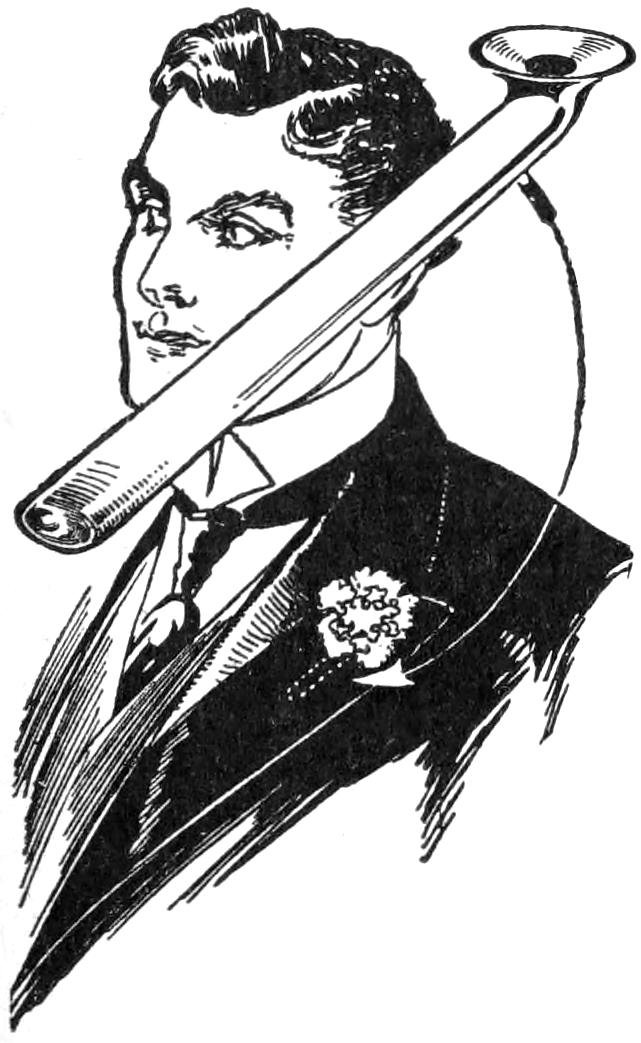
Being employed near a glass-blowing department I procured a small glass tube and made a buttonhole-bouquet holder. One end of the tube I closed and flared the other, then flattened the whole tube a bit. This tube, inserted in the buttonhole with a few drops of water in it, will keep cut flowers fresh for a whole day. If the upper end is flared just right it will fit the buttonhole and will not be seen, as the tube is hidden beneath the coat lapel.—Contributed by Frank Reid.
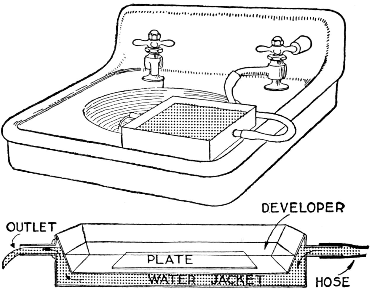
Water-Jacketed Tray for Use in Cooling a Developing Tray with a Flow of Water
Regardless of the fact that tank development for photography is the better method under most conditions, there are many who take special delight in tray development, because they enjoy seeing the picture as it develops on the plate or film.
There are many of this class of photographers both among amateurs and professionals, and they universally experience much trouble in keeping the solutions cool enough for good work in hot weather or a warm dark room. Many schemes have been used, but there is none simpler than that shown in the illustration. It is certainly better than letting the developing tray float in the bathtub, a common practice among amateurs who are compelled to use the bathroom as a dark room.
Any tinsmith can make a water-jacketed tray of zinc at a nominal price. If one expects to use it for developing films by hand, it should be made relatively deep, or at least shaped so that whatever method is used in manipulating the film will be suited to the size and shape of the tray. I had one made of zinc to accommodate an 8 by 10-in. plate and providing about ¹⁄₄-in. space all around the sides and bottom of the inner tray for the circulation of the water.
Two brass gas tips were soldered into the ends of the tray and a rubber tube was attached to one of them, as shown.[150] By connecting this tray to the bathroom hydrant the developing solution can be kept as cool as desired without slopping water where it is not wanted.—Contributed by T. B. Lambert, Chicago, Ill.
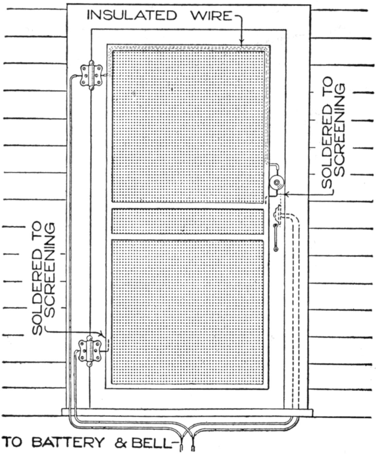
Method of Connecting a Push Button for a Doorbell on a Screen Door
Push buttons are frequently put in hallways, or other places, not accessible when the screen doors are hooked shut. By connecting an extra button on the screen door with the regular doorbell line, the service can be made to go on uninterrupted whether the screen be locked or open.
To do this, one wire, carefully insulated, from the outside button is laid under the upper molding strip of the screen, as shown, coming out through the hinge and passing down to the battery line, being concealed in any suitable manner, by molding or within the door frame. The button circuit is completed by connecting it to the screen with a short wire, the screen then acting as a conductor. If preferred, the line may be run down under the screen-door molding, and out through the bottom hinge same as with the other wire at the top. If the screen is used as conductor, a piece of wire should be connected to it near the bottom, and led through the hinge as before. In either case, after leaving the hinge, the wire must be led and connected to the battery line, to complete the circuit. It is then possible to operate the bell either from outside of the screen door or at the regular place within.—Contributed by E. M. Davis, Philadelphia, Pa.
It is often desirable to fit a piece of wood into a piece of metal by means of cutting a thread in the metal and screwing the wood therein. This can be accomplished by heating the metal to a little over the boiling point of water and screwing the wood piece into the metal while hot; or, if this is impractical on account of size, to heat the metal, make a screw plate by cutting a thread in a small piece of metal, the size and thread corresponding to the hole into which the wood piece is to be inserted, and heating it to the required temperature, then running the wood with some pressure through the thread. The wood then can be screwed into the larger piece, where it will hold firmly.
The process of heating wood without the aid of steam can be used to advantage in a number of ways; for instance, a hammer handle that is crooked can be straightened by careful heating without burning; also billiard cues, or almost anything of hard wood. It is surprising how easily it is done and how permanent the repair will be. The Indians at one time made their arrows from small hardwood twigs which were almost always crooked to start with, but after being dried they were warmed over a fire and straightened.
Another use for the application of heat is as follows: When it is desired to place a screw in a fragile piece of wood that is likely to split, if the screw is heated to a blue color and turned[151] into the wood while hot, there will be scarcely any danger of splitting. In this case do not try to use oil or a lubricant of any kind, as the screw is sure to set before it is in place.—Contributed by James H. Beebee, Rochester, N. Y.
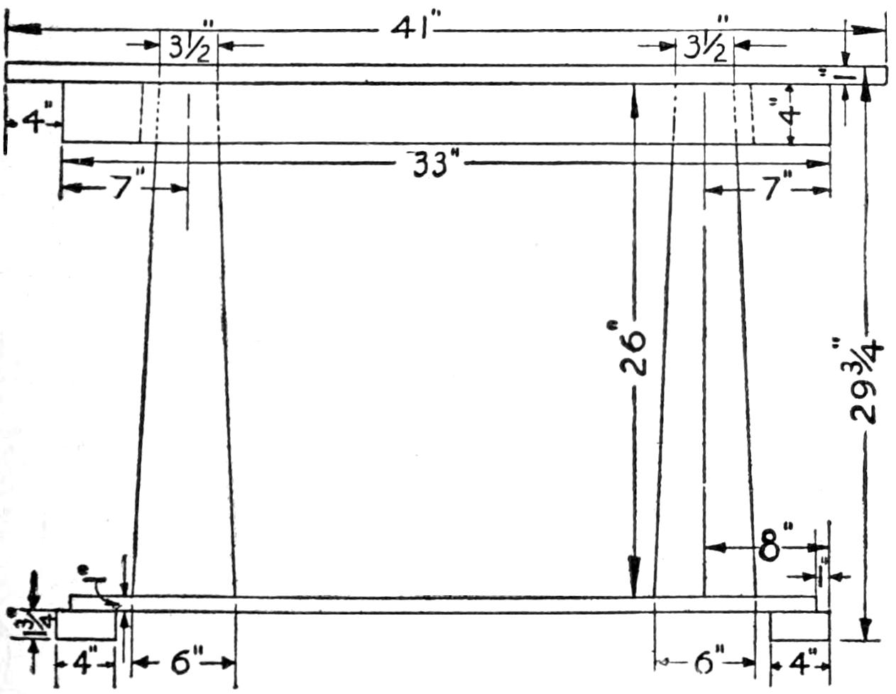
Detail of the Parlor Table, Together with Dimensions of the Pieces
The material required for the parlor table illustrated is as follows:
1 table top, 1 by 26 by 41 in.
1 bottom shelf, 1 by 15 by 35 in.
2 side rails, ³⁄₄ by 4 by 33 in.
2 end rails, ³⁄₄ by 4 by 21 in.
2 top cross braces, 1 by 4 by 19¹⁄₂ in.
4 feet, 1³⁄₄ by 4 by 4 in.
2 posts, 6 by 6 by 26 in.
2 side corner strips, 1 by 1 by 31¹⁄₂ in.
2 end corner strips, 1 by 1 by 17¹⁄₂ in.
The bottom shelf can be made of two pieces of 1-in. material, 8 in. wide, carefully glued together, and reinforced on the under side with two crosspieces, glued and screwed to it. The foot pieces are secured to the bottom shelf so as to project 1 in. on the ends and sides. In case a center support is deemed advisable, another foot piece can be added, but unless the floor is very level, rocking may result. The uprights, or posts, are made from solid 6 by 6-in. lumber, 26 in. long, carefully squared at the ends, and tapered to 4 in. square at the upper end. If desired, the posts can be made of boards, cut and fastened together to form a hollow tapered post. In either case, they should be set in about 4 in. from each side of the bottom shelf and fastened to it by means of screws.
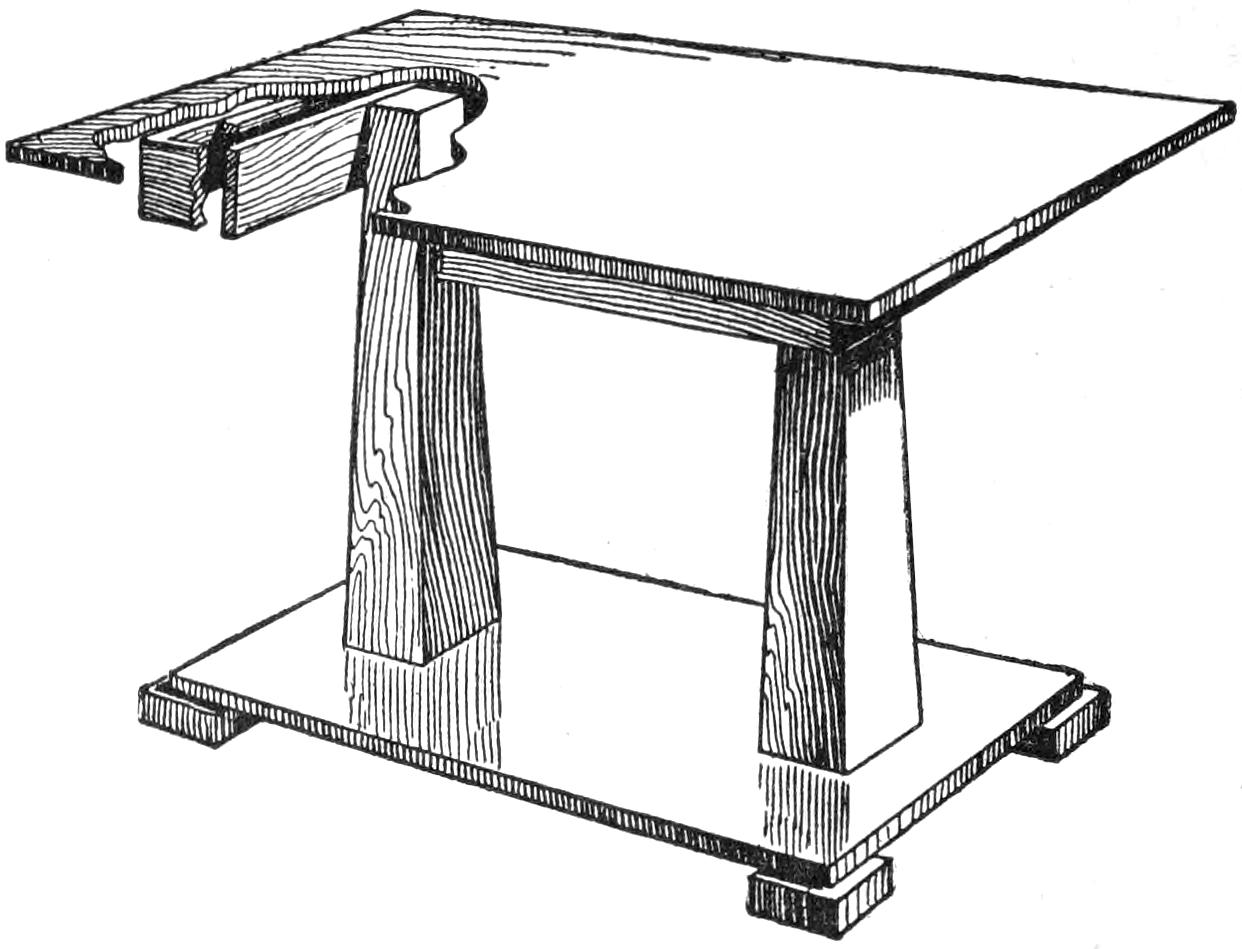
Design of a Table That will Appear Well in the Different Oak Finishes as Well as in Mahogany
The rail pieces for the table top should be cut and fitted with mitered joints at the corner to form a rectangular frame, 21 by 33 in. This is glued to the top and may be toenailed to it; but to provide a more secure bracing, a 1-in. square strip of material is fastened all around the inside edge of the rails, flush with their upper edge. The top is screwed to this. In order to prevent tipping when the top is resting on the 4 by 4-in. ends of the posts, two cross braces are provided. These should be screwed to the outer-end sides of the posts, and beveled off on their upper edges to fit the table top. They should be of such length as to have a tight fit between the side rails, and are fastened to these by means of finishing nails driven from the outside. Gluing and toenailing can also be used to secure the top more firmly to the braces; care should be taken that no nails cut through the table top. After thoroughly sandpapering and smoothing off the table, it can be finished to suit.—Contributed by H. J. Blacklidge, San Rafael, Cal.
To carry out the general arrangement of the regular electrical equipment of a large power plant, the battery circuit should have some sort of a fuse block. An excellent way to[152] make such a block is as follows: Procure a piece of glass tubing, about 1 in. long, and make a mounting for it with four pieces of sheet brass, as shown in the sketch. The brass pieces are shaped and fastened to a wood base so that their upper ends form a clamp to hold the glass tube.
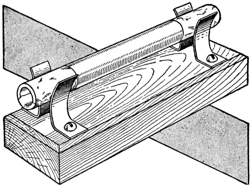
The Fuse is Well Insulated and Protected against Fire the Same as the Large Fuse
A very thin piece of tinfoil, about 1¹⁄₂ in. long, is cut ¹⁄₈ in., or less, in width, the size depending on the amount of current used. This is placed in the glass tube and the ends are bent over the edge. A piece of tinfoil is then wrapped around each end, over the ends of the inclosed piece, and pasted to the tube.
The fuse thus made is pushed into the spring clamps of the block which are connected in the circuit.—Contributed by Charles W. Meinberg, Somerville, Mass.
A very cheap, easy, and quick way to make reproductions of flowers, leaves, insects, butterflies, etc., is the following: Purchase 1 oz. of bichromate of potash and dissolve it in water. Spread this fluid over the surface of the paper upon which the picture is to be made, using a soft brush, and place it in a dark room to dry. When dry it will be a light lemon color.
The leaf, or part to be reproduced, is placed upon the yellow side of the paper and the whole exposed to the sunlight. The uncovered portions will gradually turn brown, while the part covered by the object will remain a lemon color. When the desired shade of brown is attained, remove the paper from the sunlight, and the image of the object will be on the paper.
Go over the outline with crayons or colors, and fill in the print according to the natural colors. Very beautiful pictures may be made in this way, and a butterfly made up in natural colors on a dark-brown ground is very pretty. These prints, uncolored, will keep for some time, if they are not exposed to a strong light.
Washing as ordinary photographic prints are treated will improve them a little. If the instructions are followed, many beautiful objects can be preserved in color.—Contributed by J. B. Murphy, Plainfield, N. J.
Where hot water is available the dishwasher illustrated is especially suitable. It is easily constructed and inexpensive, the only real expense being for the tank, which is 15 in. deep and 20 in. in diameter. A washer of these dimensions will hold the dishes from a table serving six to eight persons. The tank may be supported on legs if desired.
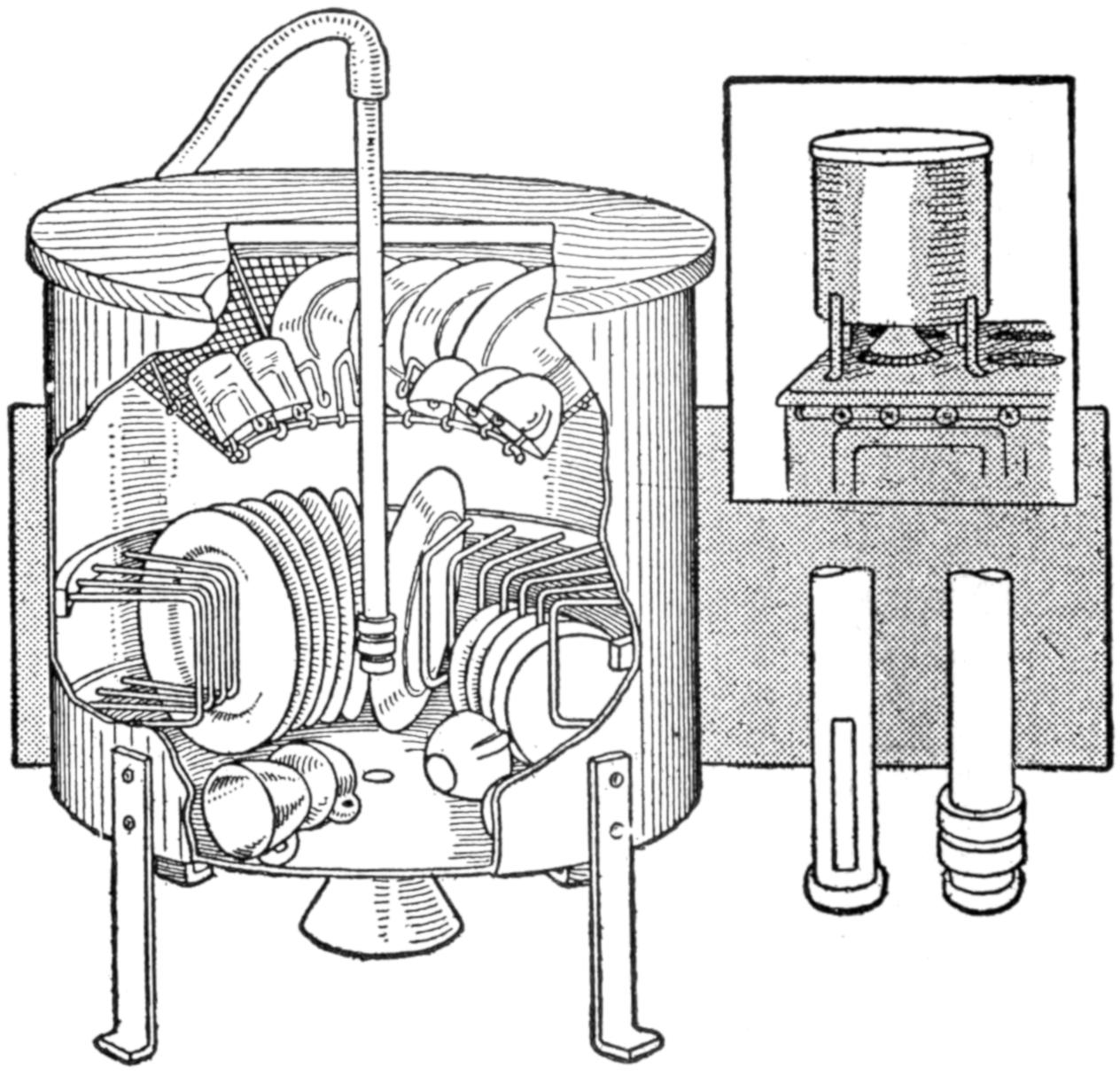
The Hot Water from the Faucet is Forced over the Dishes in a Fine Spray
The supports for holding the dishes[153] in a vertical position are made of wire in a U-shape, the ends being fastened into two wood hoops that snugly fit the inside of the tank, one near the bottom and the other about 9 in. above the first one. The wires are set about 1¹⁄₂ in. apart and radiate from the center like wire spokes in a wheel.
A funnel-shaped piece, having a hole 5 in. in diameter in the center, is made of mesh wire and hung in place with several wires running to the upper edge of the tank. Hooks are attached to the edge of the hole on which cups and glasses are hung.
The cover consists of a wood disk, with a hole bored in its center for a ¹⁄₂-in. pipe. The piece of pipe used should be 3 or 4 in. longer than the depth of the tank. A long thread is cut on the lower end of the pipe, and two rectangular holes are cut in the pipe end through the threaded part. These holes are made by cutting through the pipe as if making a slot for a key. Two large nuts are run on the threads of the pipe. These nuts should be thick enough to cover the slot in the pipe. A pipe cap is then screwed on the end of the pipe. The upper end of the pipe is attached to a hose connected to the hot-water faucet. By separating the two nuts just a little, a fine spray of water will be forced out of the holes.
When the dishes are in place the spray of hot water can be directed over them by moving the pipe up and down through the hole in the cover.
After the dishes are washed sufficiently the hose is removed and the tank placed over a gas jet so that the heat will pass up through the funnel-shaped attachment in the bottom of the tank. The dishes, already heated by the hot water, soon dry in the heat from the gas jet. If desired, the tank can be allowed to remain over the jet until the next meal is ready to serve, using a very small flame.—Contributed by W. K. Baxter, Massillon, O.
¶To empty a large sack filled with heavy material, turn or roll it over a barrel.
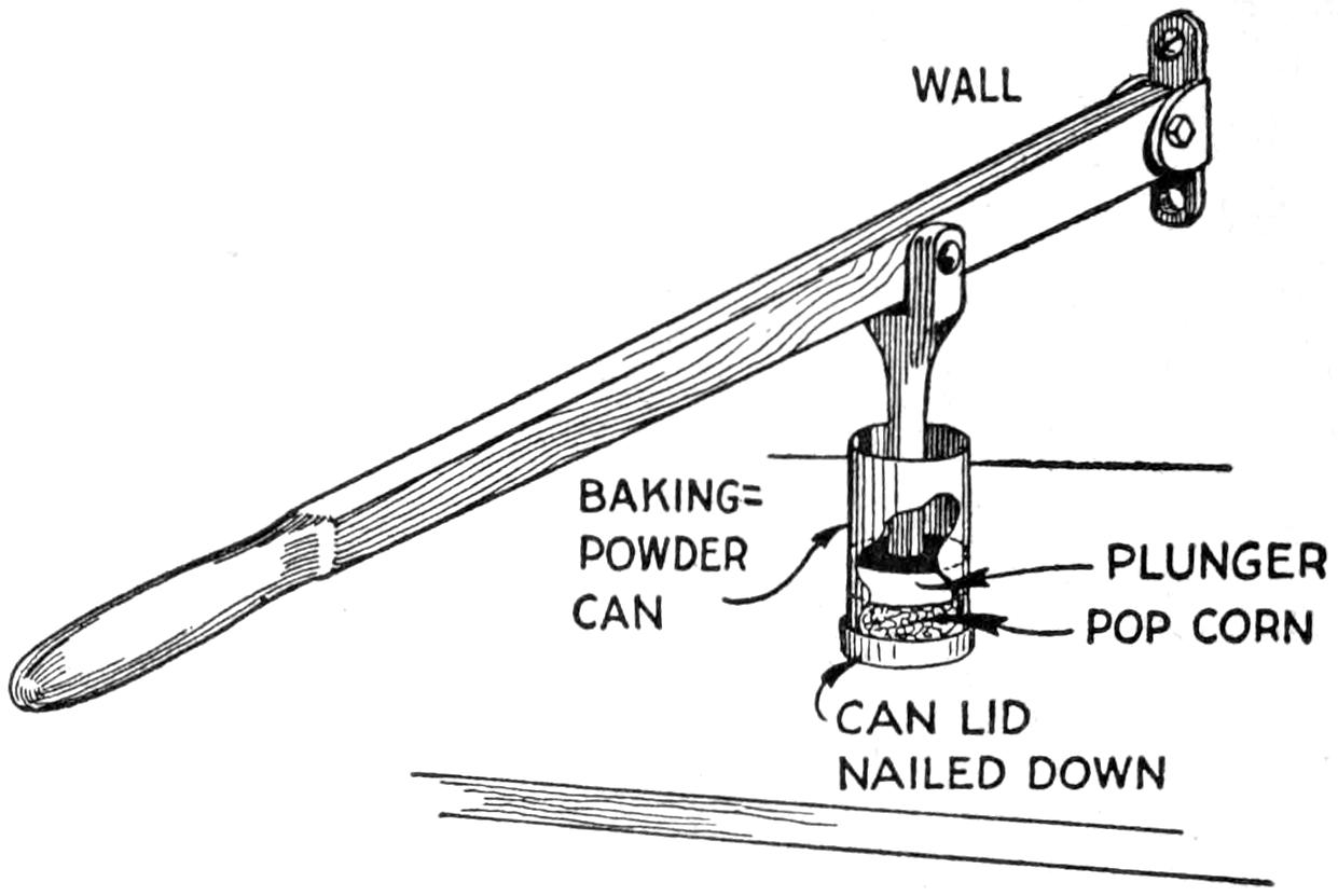
The Pop Corn When Formed into Cakes About One Inch Thick is Easily Handled
It is very difficult to take a bite from a ball of pop corn, and it becomes more difficult as the ball increases in size. As a large number of balls were required for a church entertainment I decided to make the pop corn into cakes. This was more easily accomplished than first imagined with the use of a cake-forming device as shown in the illustration. The body of the former was made of a baking-powder can with the bottom removed. The cover of the can was nailed to the top of an old table with its flange upward. A plunger of wood was made to fit snugly inside of the can and a lever, about 3 ft. long, attached to it and fulcrumed to the wall.
After the pop corn has been prepared with the sirup, it is placed in the can and compressed. The can is then lifted out of the cover and the pop-corn cake removed. This method offers a much better way to serve pop corn than in balls. In making the cakes, the can, cover, and plunger must be kept well covered with butter.—Contributed by Howard A. Hopkins, Youngstown, New York.
Having occasion to use a darning needle, the eye of which was too small to insert the yarn in the usual manner, I tried the following method with good results. A thread was doubled and passed through the eye, and the loop thus formed was used to pull the yarn through.—Contributed by Joe Henderson, Eldred, Ill.
[154]
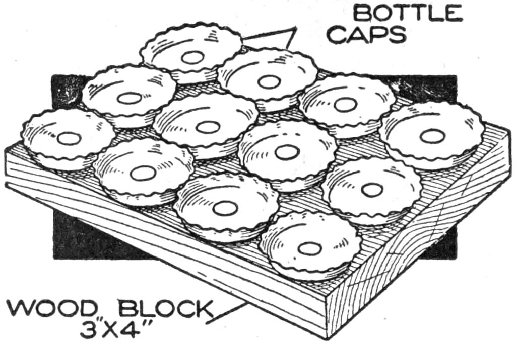
Bottle Caps Nailed to a Wood Block for Removing Scales from a Fish
All kinds of devices, both simple and complex, have been made and patented for use in scaling fish, but for a novelty I found the following, which necessity compelled me to improvise on an outing trip, to be as efficient as any of them. As usual, the commissary, in making up the outfit, neglected to take the curry comb to clean the fish, and at the same time remembered to take a plentiful supply of bottled goods. Long before it became necessary to scale any fish enough bottles had been opened to provide the basis of a tool for the purpose, which I constructed by using the small tin bottle caps, a few being nailed on a block of wood, about 3 in. wide by 4 in. long, making a splendid fish scaler, as good and efficient at home as in the camp, and both inexpensive and easily made. The sketch shows the general appearance.— Contributed by T. B. Lambert, Chicago.
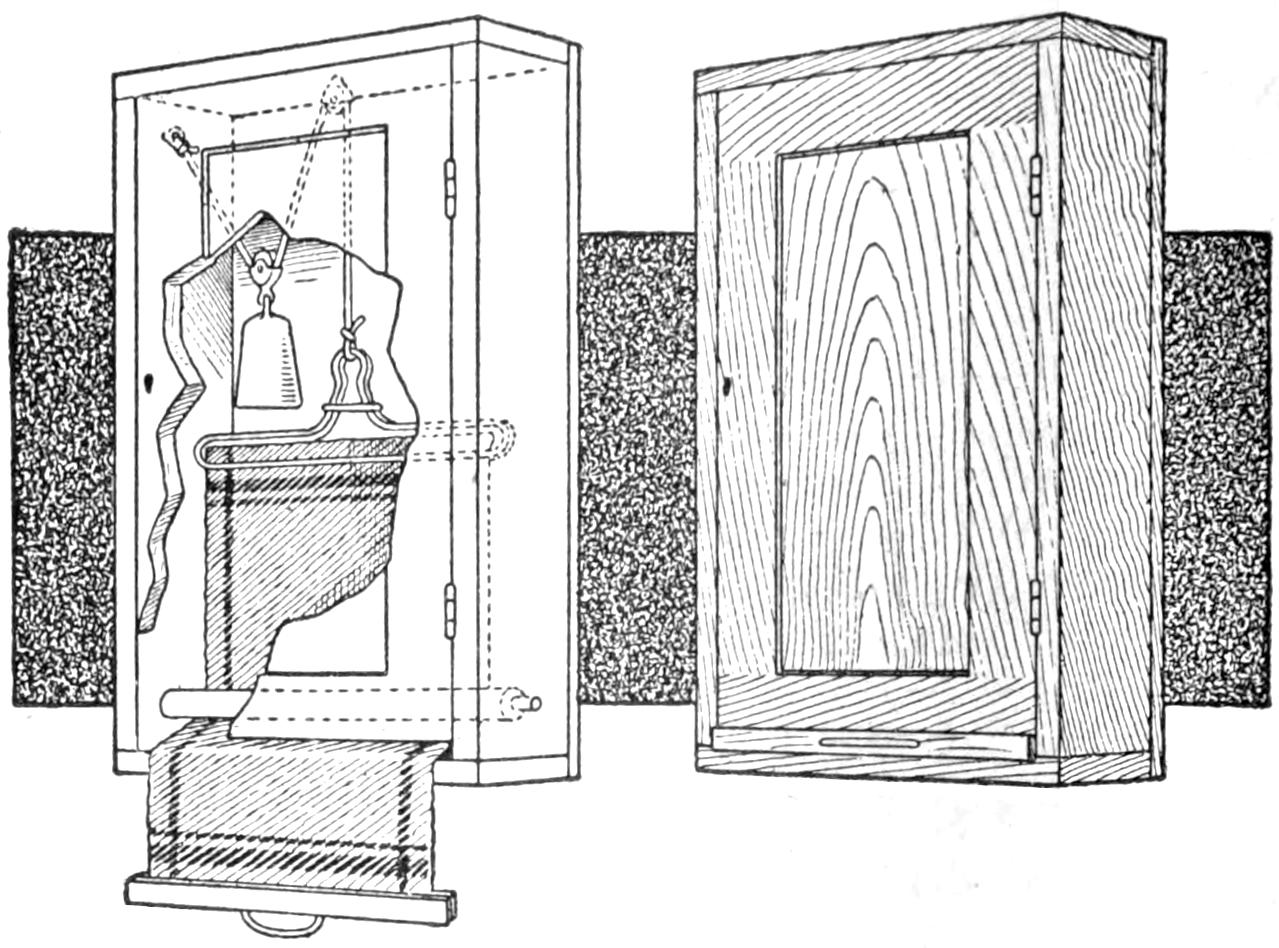
The Weight Draws the Towel into the Case Out of Sight When Not in Use
Nothing is more unsightly to a stranger entering a home than a dirty towel in either the bathroom or the kitchenette. To keep the towel out of sight I made a hanger as shown in the illustration. A wire was bent into shape similar to a clothes hanger and a sliding clip made to hold the towel in place. A cabinet was made to accommodate the towel, and the hanger was attached to a cord run over a pulley fastened at the top, through a weight pulley, and then tied to a screw eye at the top. The weight draws the towel into the cabinet. Near the bottom edge a slot was cut and a small panel fitted in it. This small panel is fastened to the lower end of the towel. It is only necessary to pull out the small panel to get at the towel. When through with the towel, let loose of it and the weight will draw it into the opening.—Contributed by Chas. C. Bradley, W. Toledo, O.
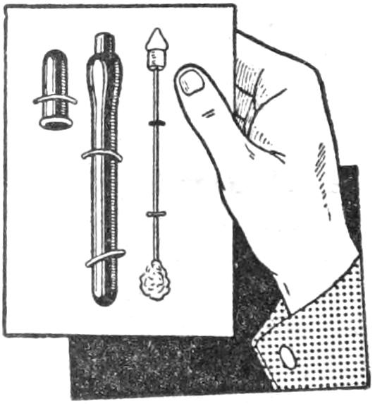
An old clinical-thermometer case can be easily turned into a vial in which to carry ammonia for insect bites. Fit a small rubber stopper in the case, then push a darning needle into the stopper so that its end will be a little more than midway in the case. Cut or break off the needle end projecting on the outside and attach a small wad of cotton to the inside end. The case is then filled with ammonia. For bee stings this works fine, as the ammonia completely neutralizes the formic acid which the bee deposits.—Contributed by E. Everett Buchanan, Elmira, N. Y.
¶The contact points of a firm-joint caliper should never be struck on hard surfaces to adjust them.
[155]
More than one kite on the same framework is known as a compound kite. The one illustrated consists of three tailless kites on one long stick, called the spine. The upper one is 3 ft.; the center one, 2 ft., and the lower one, 1 ft. in width. There will be needed for the construction of this kite a stick of light wood—spruce is best, but it may be of pine or bass—7 ft. long by ¹⁄₄ by ¹⁄₂ in. If the wood breaks easily it will be better to increase the width from ¹⁄₂ in. to ³⁄₄ in., or the stick might be made ³⁄₈ in. thick without increasing the width, but with a good spruce stick the dimensions first given will be sufficient. The stick should be straight-grained and without a twist. If the spine is twisted, the kites will not lie flat or in a plane with each other, and if one is out of true, it will cause the kite to be unsteady in the air. The bow sticks are three, the upper one being 4 ft. long by ¹⁄₄ by ¹⁄₂ in.; the center one, 2 ft. long by ¹⁄₄ by ³⁄₈ in., and the lower one, 1 ft. long by ¹⁄₄ by ¹⁄₄ in. About five sheets of tissue paper will be required, but more may be needed for color combinations. The so-called French tissue paper is much better, as it comes in fine colors and is much stronger than the ordinary tissue. It costs a trifle more, but it pays in making a beautiful kite. The Chinese rice paper is the strongest, but it comes only in natural colors.
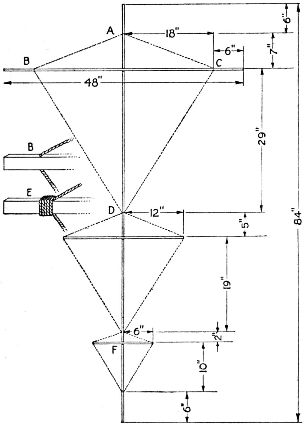
The Spine with the Bow Sticks Properly Spaced as Shown by the Dimensions
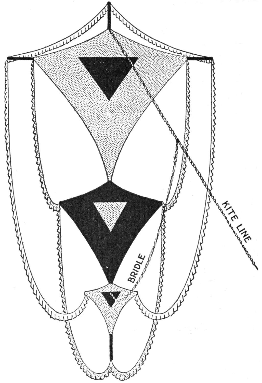
The Kite as It Appears with the Festoons Hung to the Ends of the Sticks
It will be seen that the kites do not extend to the top and bottom of the spine stick. The first bow stick is placed 13 in. from the top end of the spine, and each of its ends extends 6 in. beyond the kite for fastening the festoons. The bow sticks should be lashed to the spine, not nailed. Wind diagonally around the two sticks, both left and right, then wind between the two,[156] around the other windings. This draws all windings up tightly to prevent slipping.
To string up the upper kite, drill a small hole through the spine, 6 in. from the top, at A, and also 6 in. from each end of the bow stick, at B and C. If a small drill is not available, notch the stick with a knife or saw to hold the string. Another hole is made in the spine 29 in. from the upper bow stick, or at D. Tie the outline string at A, then pass through the hole at C, then through D, up through B and back to the starting point at A. In tying the last point, draw up the string tightly, but not enough to spring the spine or bow. Measure carefully to see if the distance AC is the same as AB, and if CD is equal to BD. If they are not, shift the string until they are equal and wind at all points, as shown at E, to prevent further slipping. Proceed in the same way with the center and lower kite, and it will be ready for the cover.
The cover tissue should be cut about 1 in. larger all around than the surface to be covered, but turn over about half of this allowance. This will give plenty of looseness to the cover. For the fringe festoons, cut strips of tissue paper, 2¹⁄₂ in. wide, paste ¹⁄₂ in. of one long edge over a string, and cut slits with scissors at intervals of 1 in. along the loose edge. After the fringe has been made, attach it as shown in the illustration. Do not stretch it tightly, but give sufficient looseness to make each length form a graceful curve and keep the sides well balanced.
To bend the bows of the upper and center kites, attach a string from end to end of each bow on the back side of the kite and spring in short brace sticks in the manner usual for tailless kites.
Attach the upper end of the bridle at A. The length of the bridle string is 87 in. and the kite line is attached to it 30 in. from A, leaving the lower part from this point to F, where it is tied to the spine, 57 in. long.
The kite should fly without a tail, but if it dodges too much, attach extra streamers to the ends of the bow sticks of the lower kite, and to the bottom of the spine.
If good combinations of colors are used a very beautiful kite will be the result, and one that will fly well.
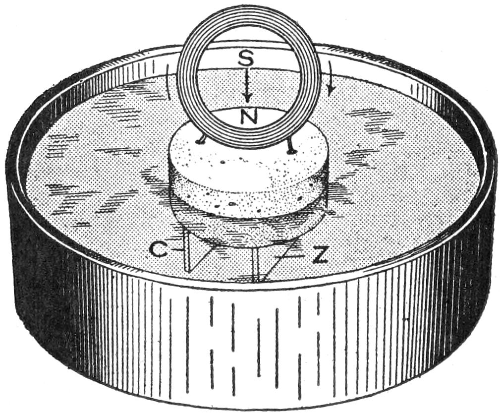
A Small Coil of Wire Mounted on a Cork Floating in Dilute Sulphuric Acid
The following simple experiment, which may be easily performed, will serve to prove the theory that there is a magnetic field produced about a conductor carrying a current, and that there is a definite relation between the direction of the current in the conductor and the direction, or polarity, of the magnetic field produced by the current. The current in the experiment is to be produced by a battery consisting of a small copper and zinc plate fastened to the under side of a large flat cork, as shown in the sketch, the whole being placed in a glass or rubber vessel partly filled with diluted sulphuric acid. A small coil of wire is formed and mounted on top of the cork, and its terminals are connected to the copper and zinc plates. The electromotive force generated will cause a current to circulate through the coil from the copper plate to the zinc plate. If the poles of a permanent magnet be presented in turn to the same side of the coil it will be found that there is a force of attraction between one pole of the permanent magnet and the coil, and a force of repulsion between the[157] other pole and the coil. If the same operation be performed on the opposite side of the coil, it will be found that the force between the poles of the magnet and the coil are just the reverse of what they were in the first case; that is, the pole that attracted the coil in the first case will now repel it, and the one that repelled it, will now attract it. Applying one of the fundamental laws of magnetism—like poles attract and unlike repel each other—it can be readily seen that the two sides of the coil are of opposite magnetic polarity.
If the direction of the current around the coil be changed, the action between the coil and the magnet will be opposite to what it was originally, and if the plates be placed in clean water, there will be no current and no attraction or repulsion between the coil and the poles of the magnet.
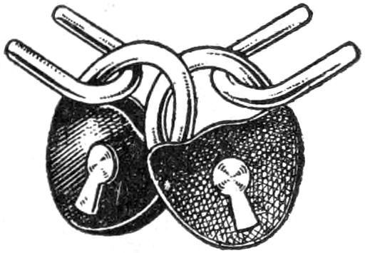
Four boys using the same shed as their workshop wished to lock it so that any one of them could enter alone. Usually only two keys are supplied with a lock, so two locks were purchased and applied to the staples as shown. Each boy was provided with a key and could enter at his pleasure.—Contributed by George Alfred Moore, Versailles, O.
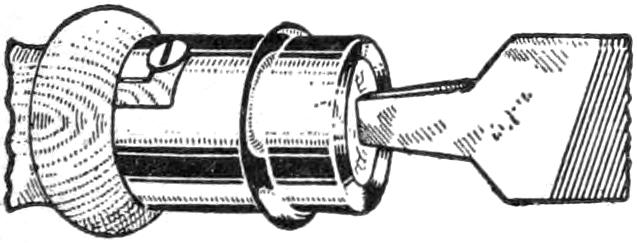
Discarded metal caps from broken gas-mantle holders should be saved, as they will come in handy for several purposes, such as ferrules on wood handles, and the like. The wire screen is removed from the end, and the cap is fastened to the handle with a nail or screw.—Contributed by James M. Kane, Doylestown, Pa.
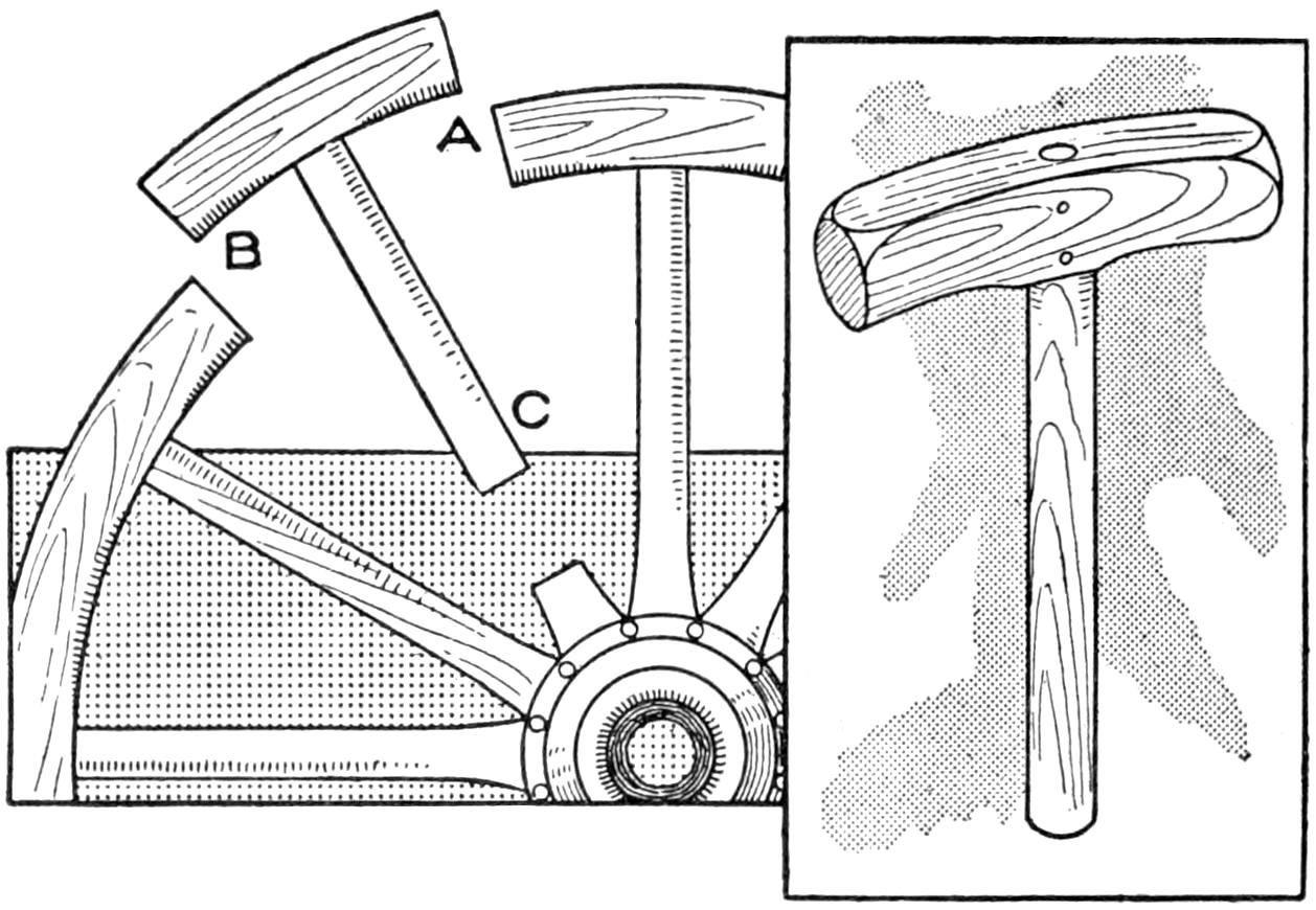
A Well-Shaped Mallet Made from a Section of a Wagon-Wheel Felly and Spoke
When in need of a mallet and if an old broken and discarded wagon wheel is at hand, one can be made quickly as follows: Cut through the rim at A and B, and through the spoke at any distance desired, as at C, for instance. The spoke is dressed into the shape of a handle and sandpapered smooth. The section of the felly is used as head and is shaped properly and fastened to the handle with two nails.—Contributed by Mark Gluckman, Jersey City, New Jersey.
Procure a thin, tapering drinking glass, a piece of thin, black thread, about 2 ft. long, and a long lead pencil. Cut a small groove around the pencil near one end. Make a slip noose in each end of the thread and slip one into the notch and place the thin glass in the other with the thread near the top. When the pencil is revolved slowly the thread will be wound on it slightly and it will slip back with a jerk that produces a ring in the glass. This may be kept up indefinitely. The movement necessary is so small that it is imperceptible. The glass can be made to answer questions by two rings for “yes” and one ring for “no.”
¶A lighted match held to the outside of a fish-pole joint causes an expansion of the outer ferrule and allows the pole to be readily pulled apart.
[158]
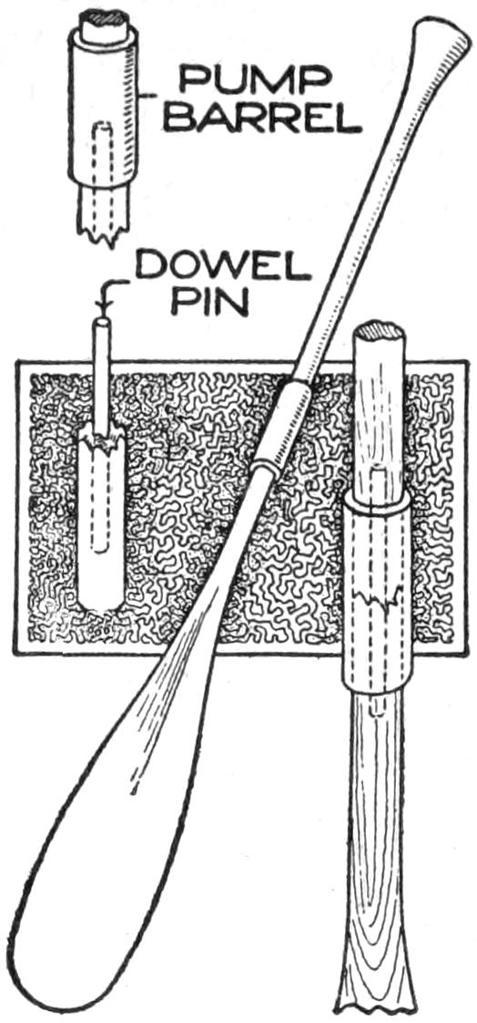
While paddling a rented canoe one day the paddle struck a rock and snapped in two a little below the center of the handle. The boatman laughed at the idea of trying to fix it, but after paying his price for the paddle I decided to try mending it. The barrel of an old bicycle pump was procured and I found that it fitted over the paddle at the break a trifle loosely. It was pushed on the handle out of the way. Then with a No. 8 bit I bored a hole 8 in. deep in the end of each broken part. Into these holes, which formed one cavity when the broken ends were brought together, was forced and glued a tight-fitting 16-in. dowel pin. The outside of the handle was then wrapped with tape for about 10 in. each side of the break, and the pump barrel was forced down over this tape until it completely and firmly enveloped the broken ends.—Contributed by Clarence G. Meyers, Waterloo, Iowa
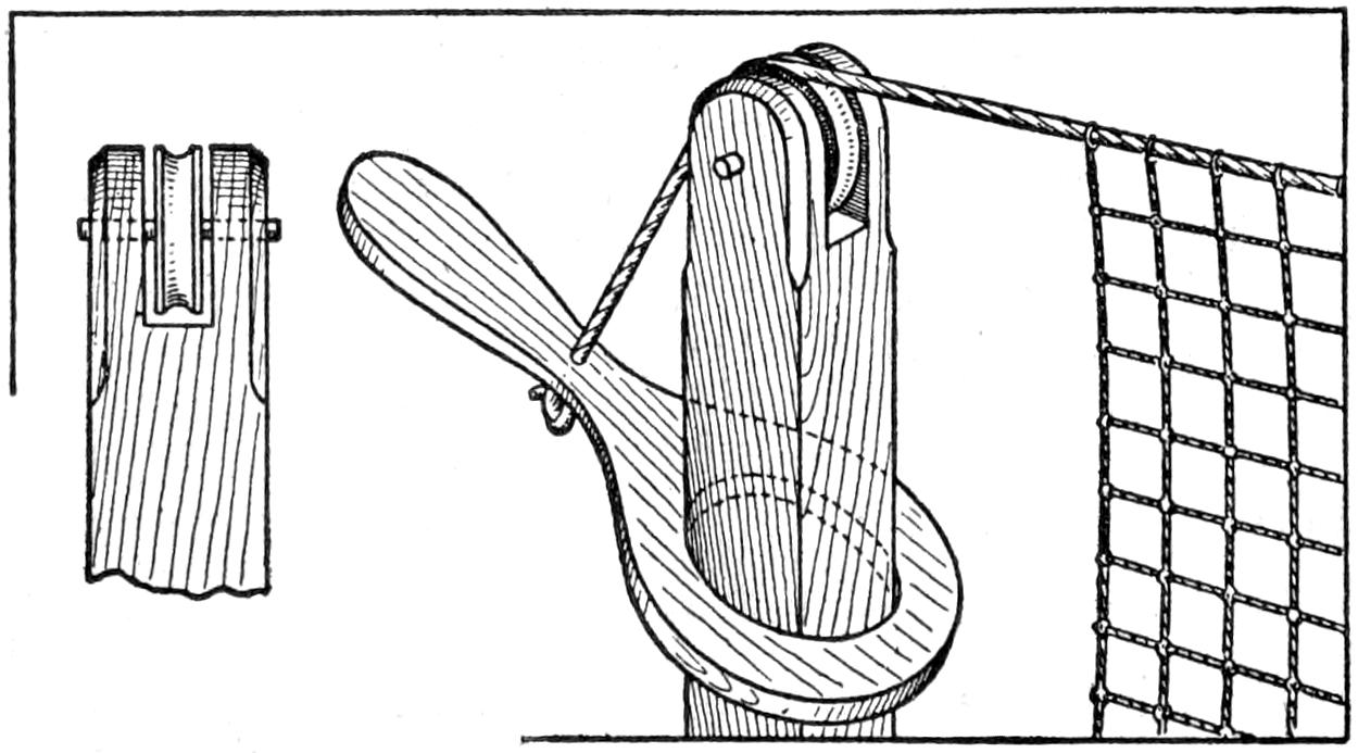
The Upper Rope on a Tennis Net Held Taut with a Lever on the Post
Tennis nets are always sagging and to keep them at the proper height requires considerable attention, especially so where the posts are not solidly set in the ground. A very effective net tightener, and one that is easy to make is the lever shown in the illustration. One end of a piece of hardwood board is shaped into a handle the other end being left large. In the latter a hole is cut to fit loosely over the post for the net. The upper end of the post is notched and a sheave pulley is placed in it so that the groove will be in line with the net. The upper rope on the net is run over the pulley and is attached to the lever handle. A downward pressure on the handle draws the rope taut and locks it on the post. It is easily removed from the post and can be left attached to the rope and rolled up in the net when not in use.
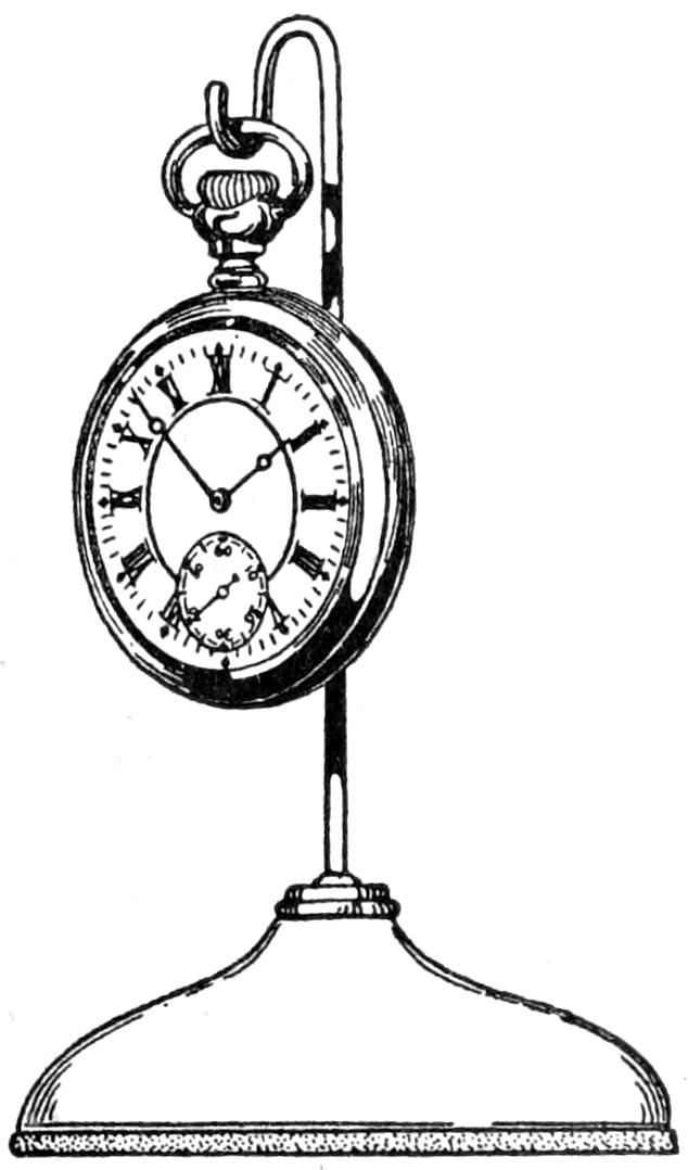
A watch holder for the desk is a great convenience for the busy worker, and many calendar devices are sold for this purpose, yet they are no more efficient than the one illustrated, which can be made from an ordinary spindle desk file. If the wire is too long it can be cut off and the bend made in it to form a hook for the watch ring.
To clean silverware or anything made of the precious metals, such as jewelry, etc., is very simple with the following method: Place a piece of zinc in a cup, dish, or any glazed ware; put in the articles to be cleaned, and pour over them a hot solution of water and carbonate of soda—washing soda—in proportions of one tablespoonful of soda to ¹⁄₂ gal. of water. This is a solution and method used by many jewelers for cleaning pins, rings, chains, and many other small articles made in gold and silver.
¶A machine should never be stopped in the midst of a fine cut.
[159]

Nearly every boy can make kites of the several common varieties without special directions. For the boy who wants a kite that is not like those every other boy makes, an eight-pointed star kite, decorated in an original and interesting manner, in various colors, is well worth while, even if it requires more careful work, and extra time. The star kite shown in Fig. 1 is simple in construction, and if carefully made, will fly to a great height. It is balanced by streamers instead of the common type of kite tail. Any regular-shaped kite should be laid out accurately, as otherwise the error appears very prominent, and unbalances the poise of the kite.
The frame for this star kite is made of four sticks, joined, as indicated in Fig. 5, with strings running from one corner to the second corner beyond, as from A to C, from C to E, etc. A little notching of each pair of sticks lessens the thickness of the sticks at the center crossing, and strengthens the frame, The sticks are ¹⁄₄ by ¹⁄₂ in. by 4 ft. long, They are set at right angles to each other in pairs, and lashed together with cord, and also held by a ³⁄₄-in. brad at the center. The strings that form the sides of the squares, A to G, and B to H, must be equal in length when tied. The points where the strings forming the squares cross each other and the sticks are also tied.
The first cover, which is put on with paste, laying it out on a smooth floor or table as usual in kite making, is plain light-colored paper. The darker decorations are pasted onto this. The outside edges of the cover are turned over the string outline, and pasted down. The colors may be in many combinations, as red and white, purple and gold, green and white, etc. Brilliant and contrasting colors are best. The decoration may proceed from the center out, or the reverse. The outside edge in the design shown has a 1¹⁄₂-in. black stripe. The figures are black. The next octagonal black line binds the design together. The points of the star are dark blue, with a gilt stripe on each. The center design is done in black, dark blue, and gilt.
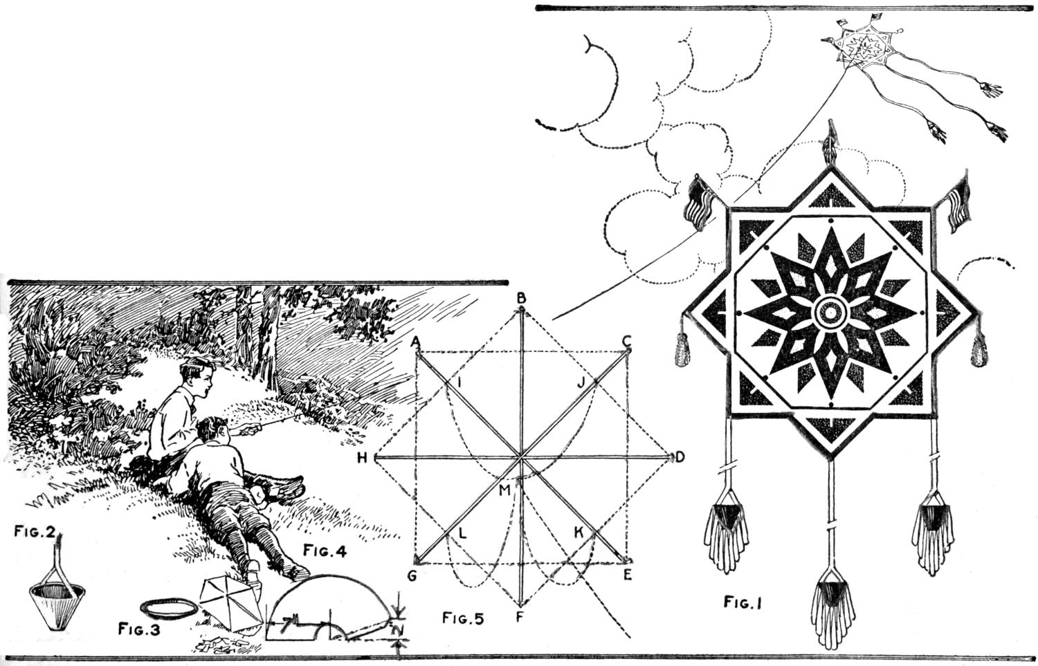
| Fig. 2 | Fig. 4 | |||
| Fig. 3 | Fig. 5 | Fig. 1 |
The Boy Who Makes a Star Kite of This Type will Have a Construction Different from the Common Run of Kites, Especially If He Decorates It in an Attractive Manner
[160]
The flags are tied on, and the tassels are easily made of cord. The outside streamers are at least 6 ft. long, and balanced carefully. Ribbons, or dark-colored lining cambric, are used for them. The funnel-shaped ends balance the kite. They are shown in detail in Figs. 2, 3, and 4, and have 1-in. openings at the bottom, through which the air passes, causing a pull that steadies the kite. They are of dark blue, and the cloth fringe is of light blue. A thin reed, or fine wire, is used for the hoop which stiffens the top. Heavy wrapping or cover paper is used to cover the hoops. It is cut as shown in Fig. 4 and rolled into shape.
A four-string bridle is fastened to the frame at I, J, K, and L, as shown. The upper strings are each 18 in., and the lower ones 32 in. long, to the point where they come together, and must be adjusted after the kite line is fastened at M.
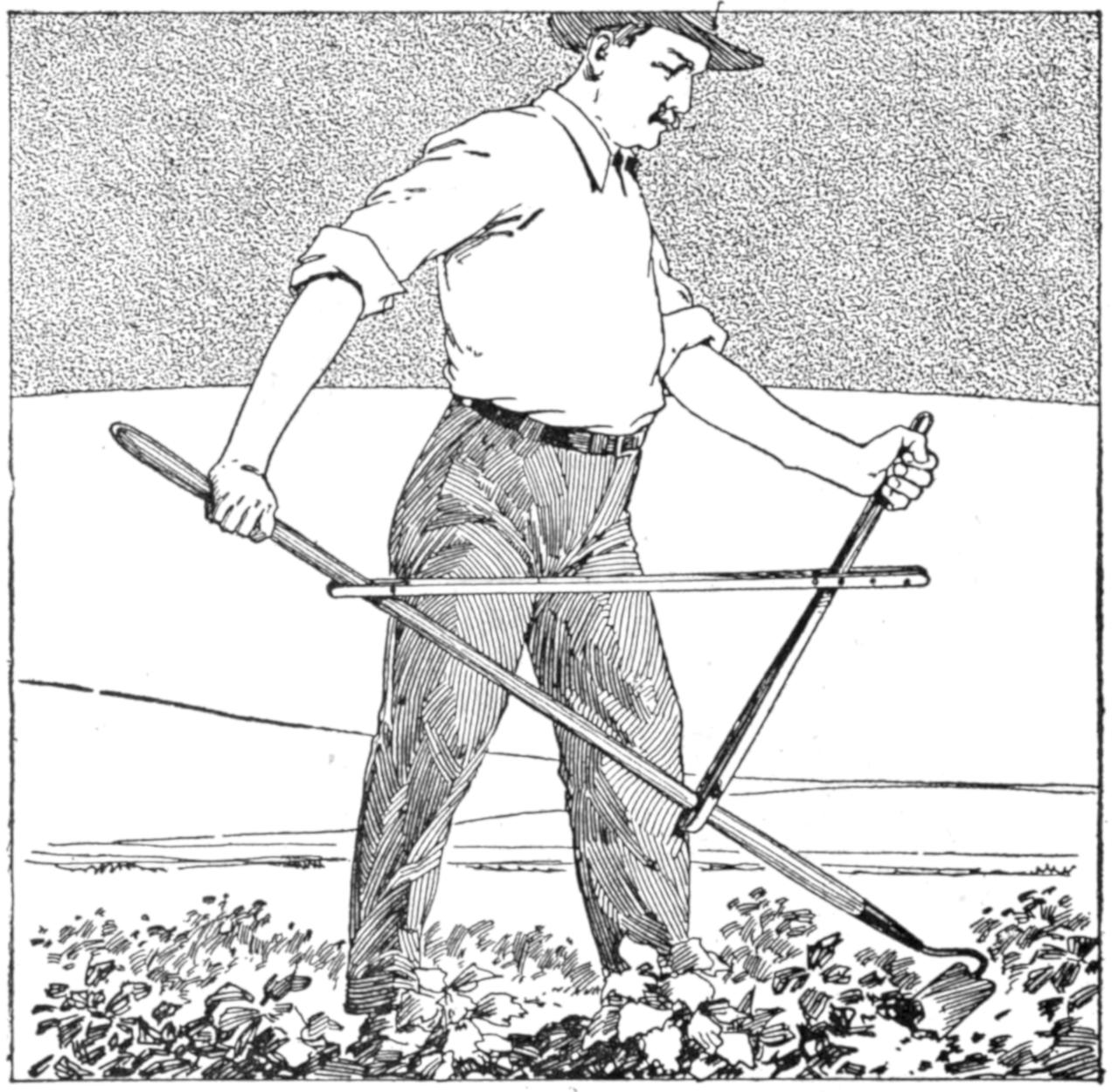
Much of the Tiring Labor in Using a Hoe or Rake is Overcome by This Simple Homemade Attachment
Anyone who has used a hoe or rake for days at a time will appreciate the labor saved by the attachment for the handle shown in the illustration. It is adjustable to various-sized persons by means of the holes at the front end of the horizontal piece. The two parts are each made of strips joined at the middle portions, and arranged to clamp on the handle of the hoe or rake. In hoeing around shrubs and large plants, the handle may be set to one side.—A. S. Thomas, Amherstburg, Ont., Canada.
Trying to take some indoor pictures I found the angle of my ordinary lens was insufficient to “get in” the various objects I desired. Not having a wide angle lens, I decreased the focal length of the lens by using a copying attachment. The results were quite pleasing and while there is some distortion and less of the plate is covered than usual, there is a remarkable increase in the angle of view. To obtain definition, it is necessary to stop the lens down, but the pictures are very clear.—Samuel L. Pickett, Denver, Colo.
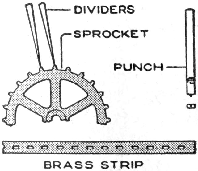
Being unable to purchase a small driving chain for sprockets made by cutting out every other tooth in gears taken from a clockwork, I used a brass strip, properly punched, and found it satisfactory. The strip was .005 in. thick and the points where the holes were to be punched out were indicated by dividers set from the gears. I made a punch from a nail leaving a small center on it as shown[161] and grinding the end to an oblong shape. I used a piece of sheet lead as a die, on which to punch the strips. The marks made by the dividers provided spots on which to set the center of the punch, making the result quite accurate.—Edward M. Davis, Philadelphia, Pa.
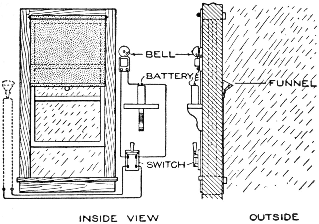
A Drop of Rain Water Completes the Bell Circuit, Thus Giving Warning of the Rain
An annunciating device, which awakens a person sleeping in a room with the window open and warns him that it is raining, so that he may close the window, is an interesting bit of electrical construction. On the outside of the house, as detailed, is a funnel fixed to the wall. At its small end, two separate wires have their terminals. The wires enter the room at the frame of the window, and connect to an electric bell, and a dry cell. A drop of water entering the funnel, flows down to the small end, falling on the terminals of the wires, and acting as a conductor, completes the circuit, ringing the bell. A switch inside cuts out the circuit, stopping the bell’s ringing.—John M. Chabot, Lauzon, Quebec, Can.
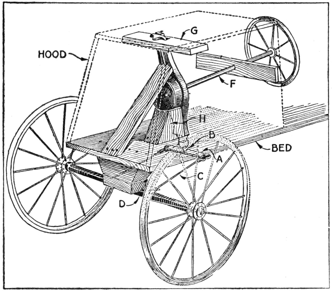
A Steering Rig That Works Almost Like That on an Automobile was Made Out of the Driving Parts of an Old Ice-Cream Freezer
In rebuilding a wagon into an automobile coaster, I used the driving rod and gears from an old ice-cream freezer, and found that it worked so well that perhaps other boys might be interested in the job. The front of the coaster was covered with a hood, and the steering wheel was set back of it, as shown. The center rod of the freezer was used for the steering post F, and an old rubber-tired wheel was made into a steering wheel. The casting from the top of the freezer, with the gears in it, and the rod on which the turning crank was fastened were set on a block, H, and braced, as shown. The shaft where the crank was fastened, at B, was set through the wagon bed. A crosspiece of iron, A, was wired to the axle D with wires C. A heavy block was used for a turntable. The top end of the casting was fastened to the hood with a brace, G, and the block H steadies the rigging also.—L. Chester Bryant, El Dorado, Ark.
In the kitchen, shop, laboratory, and other places where glass or other fragile dishes or vessels are used, a convenient pad on which to rest them can be made by stringing corks on a strong cord or wire in the form of a ring. Several rings of corks may be used to make a mat, or rings slightly larger in diameter than the bottle or vessel may be made for certain sizes of containers. If desired, the corks may be cut to fit closely on the radial joints, making the resulting ring more secure.
[162]
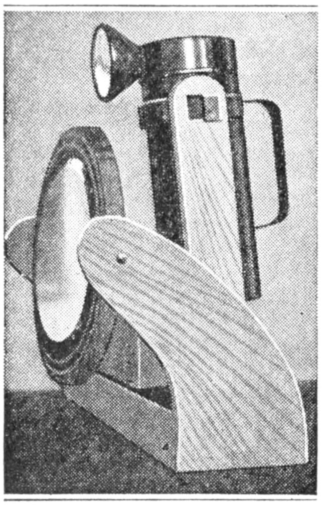
To make shaving possible in camp at night, or with little daylight, a small mirror was provided with an electric flash light. The mirror was set to swing free, in a wooden support. The light was fastened slightly above and behind the mirror. and swings at its base, so that it can be tipped upward or downward, throwing the light correspondingly. A piece of wood, 1¹⁄₄ by 3¹⁄₂ in., and as long as the mirror frame is wide, serves as a base. The arms will hold the mirror far enough in front of the lamp to allow room in which to swing. The body of the lamp is set on a block, and held between two wooden pieces, into which a band of iron was set near the top. The uprights move in an arc, pivoting at their lower fastening, on screws.—C. L. Meller, Fargo, N. D.
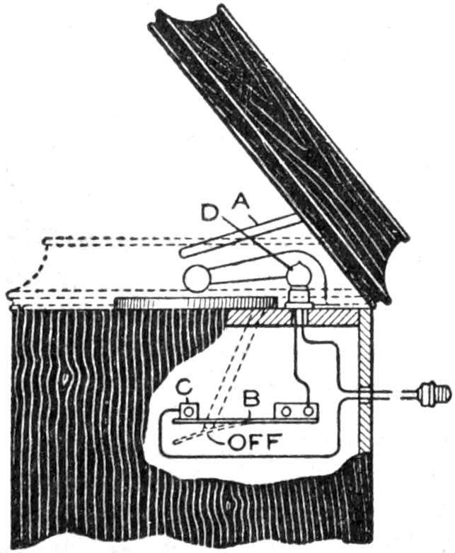
In many homes the phonograph is placed where little light is available in changing the records, setting the needle etc. An electric light which is lighted only while the cover of the phonograph is raised, is well worth installing. A metal arm, A, supports the open cover of the cabinet. When the cover is closed, this arm passes through a slot and takes the position shown by the dotted line. A strip of spring brass, B, is fastened to the inside wall of the cabinet, in the path of the arm, so that it will be pushed down to the off position, as indicated. When the arm releases the strip B, the latter presses against the contact C. A small electric lamp, D, is set in the corner, and electrical connection made to it through B and C, the plug connections passing through the back of the cabinet. When the cover is down, the electric circuit is open, and the moment it is raised, connection is made at C, and the lamp lights. The backs of most phonograph cabinets may be removed easily to make these changes.—M. C. Ball, Kansas City, Mo.
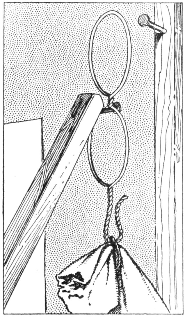
To hang small sacks or other articles out of reach overhead, so that they may be easily taken down, I use a double-eye hook which I made of wire. A single piece of wire is used, and twisted into two loops as shown, and then formed into a twisted hook. I use a pole with a nail, hooking it into the lower loop, to raise the parcel; this leaves the upper loop free to be hooked on the nail above.—E. B. Warren, Garnet, Mont.
It takes little trouble to keep aluminium pots and pans shining if they are cleaned frequently with steel wool, water, and a nonalkaline soap. Use a very fine grade of the wool, and give the utensils a few rubs frequently rather than attempt to clean them only occasionally, when much soiled.—L. P. Langan, Denver, Colo.
[163]

The old-four monoplane model, made famous by its wonderful flights, is one of the most graceful that has been built. Its large size and slow, even glide make it a much more desirable flier than the ordinary dartlike model. It gives one a true insight into the phenomena of heavier-than-air flight. This machine, when complete, should weigh 9 oz. and fly 1,200 ft., rising from the ground under its own power and landing lightly. Its construction is simple, and with careful reference to the sketches, an exact reproduction may be made.
For the motor bases, A, Fig. 1, secure two spruce sticks, each 48 in. long, ³⁄₈ in. wide, and ¹⁄₄ in. thick, and fasten a wire hook on one end of each stick with thread wound around after giving it a coat of glue. These hooks are to hold one end of the rubber bands that act as the motive power, and are designated by the letter B. At the opposite ends of the sticks, at C, bearings are provided, which consist of blocks of wood, each 1 in. long, 1 in. wide, and ³⁄₈ in. thick. These are also bound in place with thread after gluing them. Holes are drilled through the blocks lengthwise and then lined with bushings made of brass tubing, ¹⁄₁₆ in. in inside diameter. The two motor bases A are connected with four cross sticks, D, each 9 in. long and ³⁄₁₆ in. square. These are bound and glued on the under side, one near each end and the others equidistant each from the other and from the nearest end stick. The front bumper E is made of round rattan, ¹⁄₈ in. in diameter.
The Mechanical Bird will Run About Five Feet on the Ground and Then Rise and Fly
The alighting gear is next in order of construction. This is made as shown entirely of bamboo, ³⁄₁₆ in. square. The pieces marked F are 11 in. long; G, 9¹⁄₂ in. long, and the cross bar H, 11 in. long. At the rear, the pieces J are 13 in. long; K, 4¹⁄₂ in. long, and the cross piece L, 11 in. long. The distance between the points M and N, Fig. 2, is 6 in., and between O and P, 9 in. The bamboo is easily curved by wetting and holding it for an instant in the flame of a candle. It will hold its shape just as soon as it becomes cold. The wheels are made of tin, 1¹⁄₂ in. in diameter, borrowed from a toy automobile. The axles are made from wire, ¹⁄₁₆ in. in diameter.
The wing spars Q are made of spruce, ³⁄₁₆ in. wide and ¹⁄₄ in. thick. Those for the front are 30 in. long, and[164] for the rear, 36 in. long. The ribs R are made of bamboo pieces, ¹⁄₁₆ in. square, 5 in. long for the front plane, and 6 in. for the rear. These are bound and glued on top of the spars, 3 in. apart. They are given a slight upward curve. The round ends are made of ¹⁄₁₆-in. rattan.
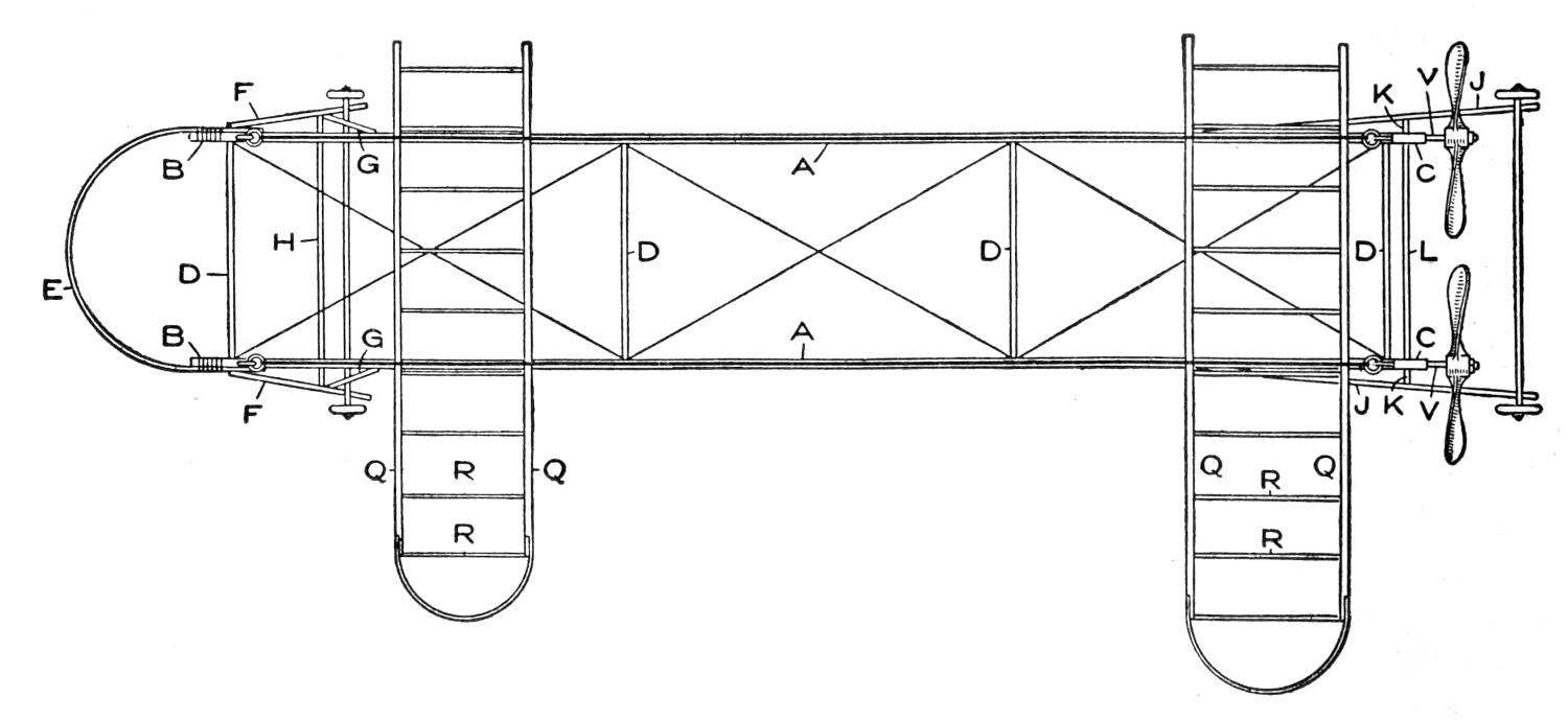
Fig. 1
The Motor Base is Made of Two Spruce
Sticks Joined Together with Four Cross
Sticks, Bound and Glued to the Under Side
It is rather difficult to make good propellers, but with a little time and patience they can be shaped and formed into good proportions. Procure two clear, straight-grained blocks of white pine, 8 in. long, 1¹⁄₂ in. wide, and ³⁄₄ in. thick. Draw a diagonal line on one block from opposite corners, as shown at S, Fig. 3, then on the other block T, draw the line in an opposite direction. Turn the blocks over and draw opposite diagonals, as shown by the dotted lines. Draw a circle on each side exactly in the center, ¹⁄₂ in. in diameter. Drill ¹⁄₁₆-in. holes through the centers of the circles for the propeller shafts. The wood is then cut down to the lines drawn, leaving only enough material so that they will not break easily. The face of the blades should be flat and the back rounded. Leave plenty of stock near the hub. After the faces have been finished, the blades are shaped as shown at U. The propellers should be finished with sandpaper to make them perfectly smooth, as much of the success of the model will depend upon them. It will be a good plan to shellac them, and also the frame and the alighting gear. Aluminum paint costs but little, and it makes a fine finish for a model aeroplane.
The propeller shafts V, Fig. 1, 2, and 4, are cut from bicycle spokes. An eye for the rubber band is bent in the spoke, about 2 in. from the threaded end. The end having the threads is run through the bearing block C, Fig. 4, and the propeller fastened on with a small washer on each side of it by means of two nuts, W, cut from a bicycle nipple. These nuts may be turned up tightly with pliers.
The planes are covered with tissue paper put on tightly over the tops of the ribs, using a flour paste. The planes are movably fixed on the motor bases A by tying at the four points of contact with rubber bands. This makes it possible to adjust the fore-and-aft balance of the machine by changing the position of the planes.
The motive power, which is the most important part of the entire machine, consists of rubber bands. There are three ways of obtaining these bands. It is best, if possible, to purchase them from an aeroplane supply house. In this case, procure about 100 ft. of ¹⁄₁₆-in. square rubber, 50 ft. for each side. These are wound closely between the hooks X. This rubber can be taken from a golf ball. It will require about 40 strands of this rubber, which is removed by cutting into the ball, on each propeller. Another way of obtaining the bands is to purchase No. 19 rubber[165] bands and loop them together, chain-fashion, to make them long enough to reach between the hooks without stretching. About 30 strands on each propeller will be sufficient. The hooks X are made in the shape of the letter “S,” to provide a way for taking out the rubber bands quickly. To prevent the hooks from cutting the rubber, slip some ¹⁄₁₆-in. rubber tubing over them. The rubber bands, or motor, when not in use, should be kept in a cool, dark place and powdered with French chalk to prevent the parts from sticking together.
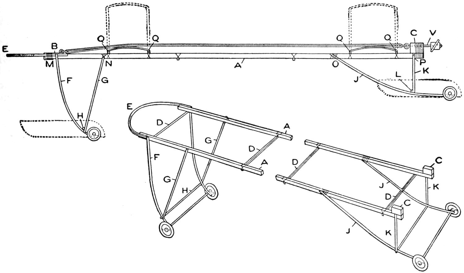
Fig. 2
The Alighting Gear is Made Entirely of Bamboo and Attached to the Under Side
of the Motor Frame
With the model complete, flying is the next thing in order. With a machine as large as this one, quite a field will be necessary to give it a good flight. Test the plane by gliding it, that is, holding it up by the propellers and bearing blocks on a level with your head and throwing it forward on an even keel. Shift the planes forward or back until it balances and comes to the ground lightly.
Winding up the propellers is accomplished by means of an eye inserted in the chuck of an ordinary hand drill. While an assistant grasps the propellers and motor bearings the rubber is unhooked from the front of the machine and hooked into the eye in the drill. Stretch the rubber out for about 10 ft., and as it is wound up, let it draw back gradually. Wind up the propellers in opposite directions, turning them from 400 to 800 revolutions. Be sure to wind both propellers the same number of turns, as this will assure a straight flight.
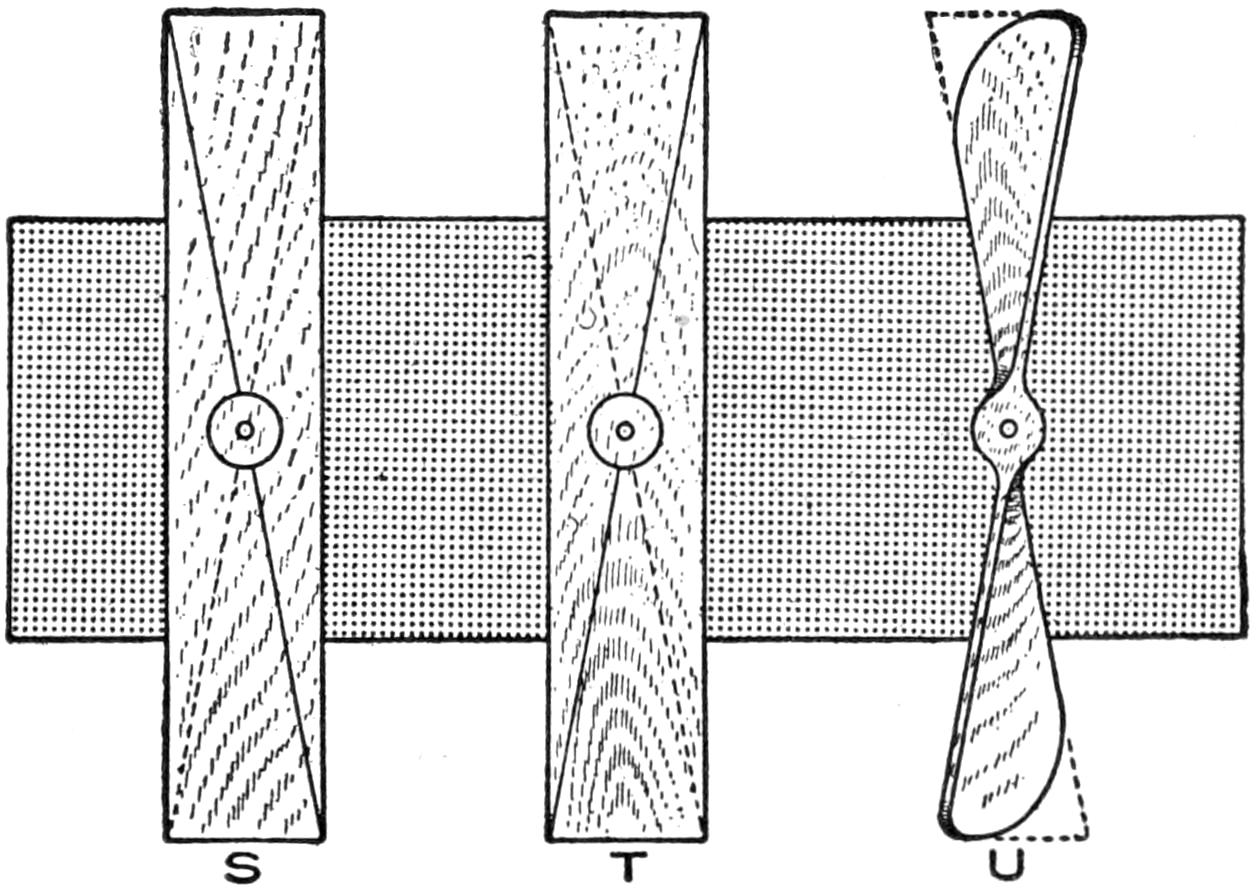
Fig. 3
The Most Difficult Part of Making the Propellers can
be Overcome with a Little Patience
Set the machine on the ground and release both propellers at once, and at the same time push it forward. If everything is properly constructed and well balanced, the mechanical bird will run about 5 ft. on the ground and then[166] rise to 15 or 20 ft. and fly from 800 to 1,200 ft., descending in a long glide and alighting gracefully.
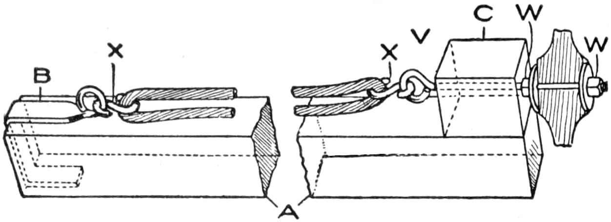
Fig. 4
The Motive Power, Which Is the Most Important
Part of the Machine, Consists of Rubber Bands
If the machine fails to rise, move the forward plane toward the front. If it climbs up suddenly and hangs in the air and falls back on its tail, move it toward the back.
After the novelty of overland flights has worn off, try flights over the water. To do this the wheels must be removed and four pontoons put in their place, as shown by the dotted lines in Fig. 2. The pontoons are made over a light frame, constructed as shown in Fig. 5. The frame pieces are bamboo, ¹⁄₈ in. square. Each one is 8 in. long, 4 in. wide, and 2 in. deep. The covering consists of writing paper glued in place, after which the whole surface is covered with melted paraffin to make it water-tight.
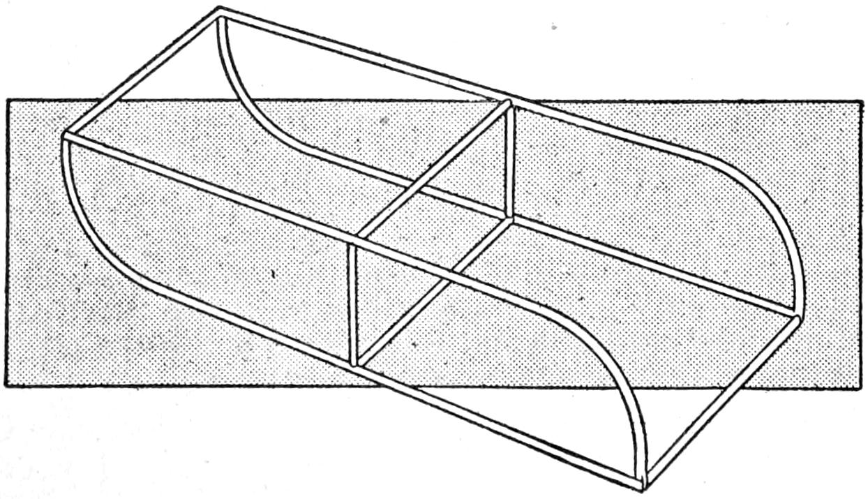
Fig. 5
Framework for Constructing Pontoons by Covering
Them with Writing Paper Soaked in Paraffin
No doubt various methods will be suggested by the time such flights are made, such as smaller planes for racing, larger ones for altitude and duration, etc. To make the machine carry weights, build a duplicate set of planes and fasten them 6 in. above the others by means of struts, ³⁄₁₆ in. square, forming a tandem biplane, as shown by the dotted lines in Fig. 2.
Patience is the one thing necessary in model budding. Sometimes a machine carefully made will not fly, and no one can make it do so until some seemingly unimportant alteration is made.
The making of these trammels is a very nice workshop problem for a school, as it requires a very small amount of stock and a corresponding degree of skill, and at the same time adds a little something to the general shop equipment.
The brass is best procured in strips, which may be had in different widths, except the bar, which is ¹⁄₄ in. thick and not less than ³⁄₄ in. wide. The steel for the points may be the ordinary steel, or if the trammels are to be used on woodwork, very satisfactory points can be made of heavy nails.
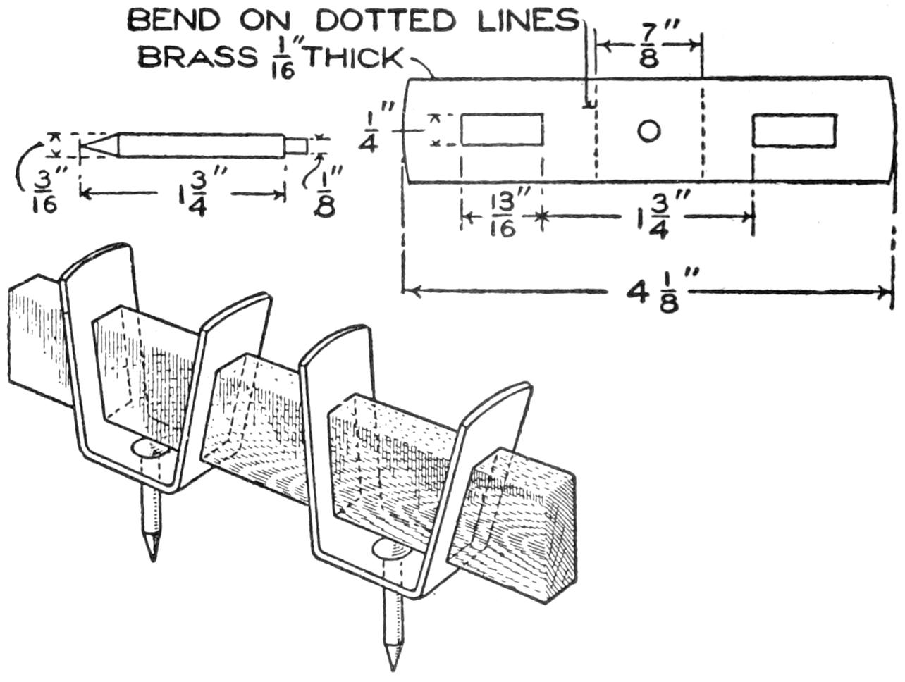
Trammel Points Made of a Nail and a Brass Strip to Fit the Bar
Cut two pieces of brass, 4¹⁄₄ in. long, and straighten them with a wood or rawhide mallet on a surface plate. Draw center lines both ways through each piece and lay out the openings for the bar with a sharp scriber, and make a center-punch mark for the ¹⁄₈-in. hole that is to be drilled at the intersection of the center lines. Mark the lines where the piece is to be bent, and with a pair of dividers lay out the ends and shape them with a file.
The center hole and bar openings are next drilled, and the latter finished by filing. It is better to plane up a short piece of hard wood, ¹⁄₄ by ¹³⁄₁₆ in., and[167] use it as a gauge in filing the rectangular openings than to try to make them by measurement. Polish the brass pieces with a piece of fine emery cloth or paper, rubbing it in straight lines lengthwise of the stock.
The bending is done by clamping the pieces in a vise and bending first one side and then the other on the lines indicated. This will require some care, as the upper ends should be 1¹⁄₄ in. apart on the inside when the bending is complete. To insure the same angle on both sides, a template of wood is used, and the pieces are carefully bent to fit it.
The holes for the points are reamed tapering from the inside, where they are riveted in place. The points are filed to shape and polished, which is best accomplished in a lathe. Clamp one of the points in an upright position in a vise with the shouldered end up. Slip one of the brass pieces in place and rivet by upsetting the projecting end with a light hammer.—Contributed by J. A. Shelly, Brooklyn, N. Y.
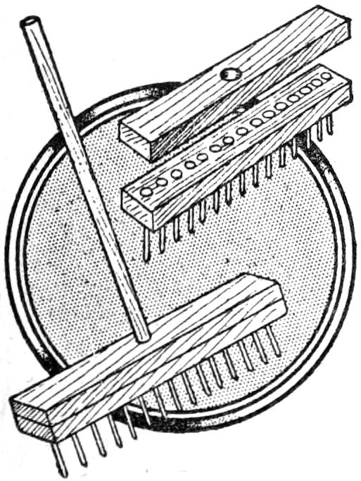
A lawn that shows patches of grass with bare spots, or only partly covered with grass can be sown with seed that will fill the uncovered places by using the tool illustrated. It is made of a block of wood, 1 in. thick, into which several large nails are driven so that their ends project about 1¹⁄₂ in. Another block is fastened on top of the nail heads to keep them from pushing out of their holes. A handle is attached to the latter block.
The tool is used by driving it into the earth where there is no grass, or in thin places, and the grass seed is sprinkled into the holes. In raking over the lawn the young grass is not so apt to be torn out and destroyed before it gets a good root.—Contributed by Edmund H. Trabold, Orange, N. J.
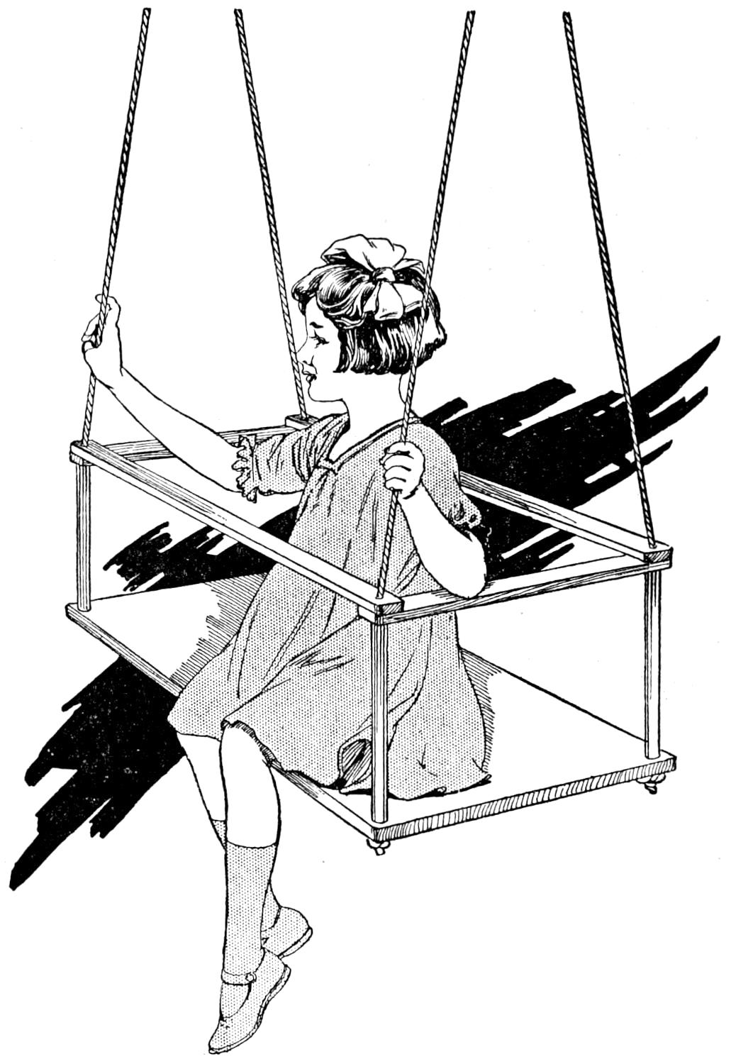
A Porch Swing Having a Rail That Incloses the Person Sitting in It
The seat of the swing consists of a board, 30 in. long, 14 in. wide, and 1 in. thick, with holes bored in each corner for the ropes. The rail at the top is made of four oak pieces, two of them 30 in. long, for the sides, and the other two 18 in. long, for the ends; all 3 in. wide and ⁷⁄₈ in. thick. The ends of these pieces are finished rounding, and holes are bored in them for the supporting ropes. The supports for the rails consist of four pieces of ³⁄₄-in. pipe, 15 in. long. The ropes are run through the holes in the ends of the rails, down through the pipes and through the holes in the seat board, where they are knotted.
A rope tied to a convenient post or screw hook makes a handy way to give motion by pulling. To get into the swing, raise one of the side rails on the rope.—Contributed by Ward M. Mills, Bakersfield, Cal.
¶Cover the top and side of ice in a refrigerator with a piece of Canton flannel, and the ice will last longer.
[168]
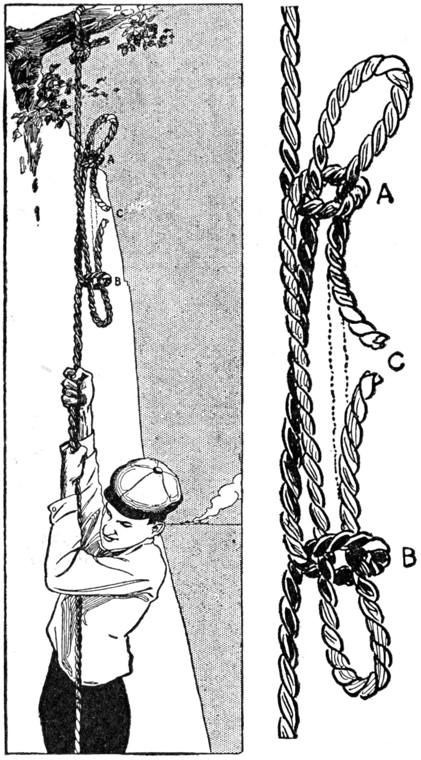
Only a Small Portion of the Rope will be Left on the Projection
The knot shown has a peculiar characteristic which enables a person to recover the rope after letting himself down from some elevated position. After the rope has been tied firmly to some support, as a limb of a tree, tie this knot, or “sheepshank,” as high up as possible. Close inspection will show that one of the three sections of the knot holds no part of the weight below. This section is identified as the portion which projects through the loops A and B at both ends. The other sections project through at one end only. When the knot has been arranged, slide down carefully to a position just below it and cut the rope at C; then descend to the ground. By shaking the rope the knot may be loosened, and only a short piece will be left attached to the support.—Contributed by F. R. Gorton, Ypsilanti, Michigan.
To write red, or any other color, on a one-color ribbon typewriter place a long enough piece of red carbon paper, or the color desired, between the ribbon and the paper. It will hold its place quite well, does the work as well as a two-color ribbon used on expensive machines, and does not cost very much.—Contributed by Leslie E. Turner, New York City.
The effect of this trick is not new, but the method is a new one. A card is selected by a spectator and noted, then returned to the pack, which is shuffled by the one drawing the card. Despite the thorough mixing the correct card is located by cutting the pack. The secret is this: When the card is chosen, the chooser is allowed to remove it from the pack. The performer then takes it and holds it up and asks the audience to fix it in their minds. While doing this, allow the thumb nail of the index finger to slightly graze the edge of the card. This will not show, nor can it be detected by the holder, and he suspects nothing of the kind. When returned to the deck and shuffled the pack is evened up for cutting. A glance at the edges will show a small white spot distinctly, as the scraped edge will contrast with the other soiled cards. It is simple to cut the pack from this key.—Contributed by John C. Moorehead, Minneapolis, Minn.
Instead of chasing the little fish up and down the stream to catch enough for bait, try putting a clean bit of shell in a wide-mouth jar and holding it in the water. The minnows will be attracted in great numbers, and it is an easy matter to dip them up. A bit of shell can be used also in a net. The white, shining shell seems to be a good lure for the little fellows.—Contributed by Miriam Colchester, Amherst, Can.
[169]
A fine or coarse writing or lettering pen can be produced quickly by means of an oilstone. By rubbing it at the sides of the nibs, the pen is made finer, and grinding across the ends makes it coarser. By grasping the penholder in the normal writing position, and writing lightly on the surface of the stone, the pen may be ground to the style of the user, making it write more smoothly. If the pen scratches, a slight touching up on the stone, which should be a fine hone, will remedy the difficulty.
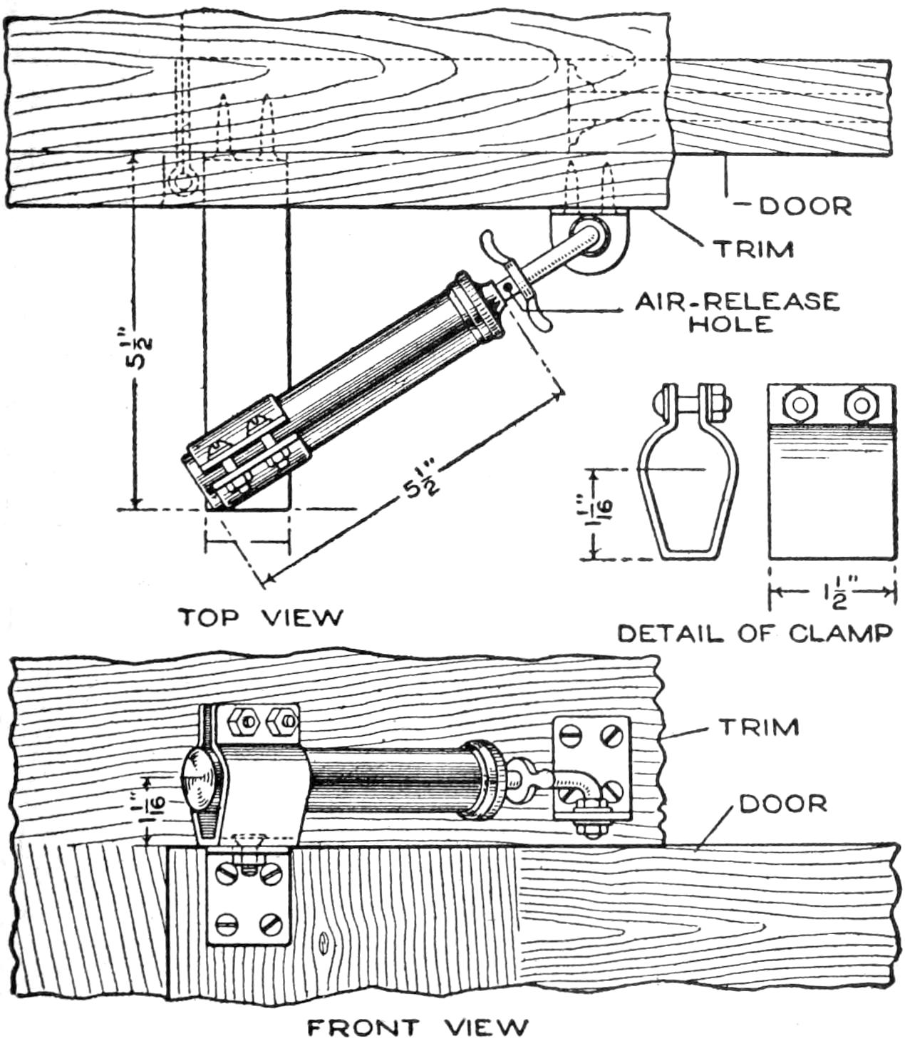
This Neat and Effective Door Check was Made of an Old Bicycle Pump and a Strip of Iron, Shaped and Polished
A door was provided with a heavy coiled spring that caused it to slam shut, and in order to overcome this nuisance, a check was made from an old bicycle pump. The fittings being worked out neatly, did not mar the appearance of the woodwork. Band iron, ¹⁄₈ by 1¹⁄₂ in., was used for the fittings. A clamp, as detailed, was made to hold the end of the pump cylinder. A bracket, 5¹⁄₂ in. long, of similar iron was fastened to the door, as shown, with screws, and the clamp bolted to it. The end of the plunger was extended and bent at a right angle, so as to pivot in a small angle bracket attached to the trim, as shown in the front view. An air-release hole was provided, as indicated, so that the air was freed from the cylinder gradually as the door closed, thus preventing slamming.—P. P. Avery, Garfield, New Jersey.
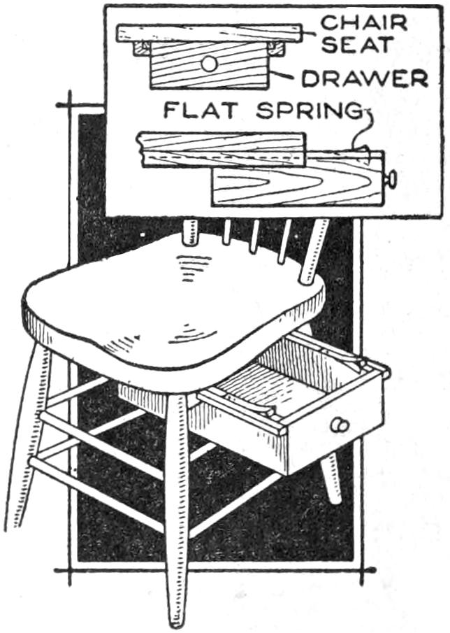
For the householder who does small repairing occasionally at home, a sliding drawer under his working chair will be found a convenience. The tools are always handy when he sits down to his work, and he can put them away again without arising from the chair. This arrangement is also useful in small shops where a chair or stool is used for tinkering and light bench work.—James M. Kane, Doylestown, Pa.
Instead of the customary dark room, with the expense of red incandescent lamps or the evil-smelling oil lamp, the photographer who works during the day should have a red room, obtained by means of a window with panes of red glass. The amateur can cover the windows with red cloth, through which will penetrate a diffuse red light of the desired quality. This is far superior to the common practice of providing an opaque screen, blocking up the windows, etc., and the screen can be made of red cloth instead of black cloth, just as handily. Proper ventilation should, of course, be provided.—Alfred J. Miller, Albuquerque, N. M.
[170]
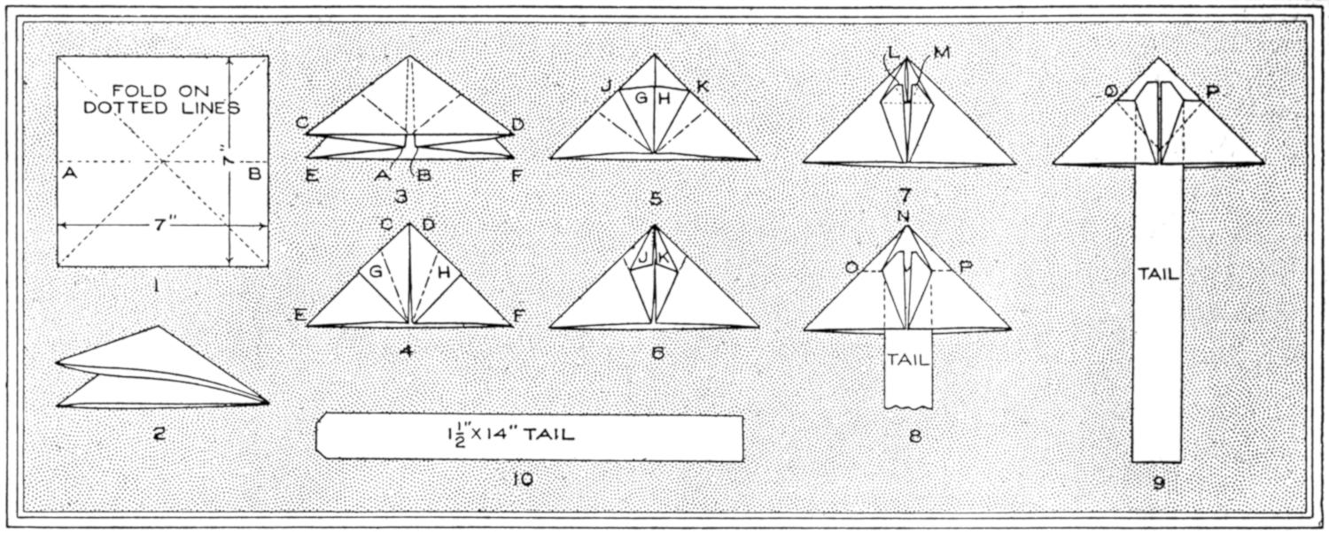
| 1 | 3 | 5 | 7 | 9 |
| 4 | 6 | 8 | ||
| 2 | 10 | |||
The Method of Folding the Paper is Indicated Clearly in the Diagram, Which are to be Followed in the Order of Their Numbering, the Tail being Inserted Separately
An interesting bit of paper construction is a small monoplane made from a 7-in. square of paper, folded as indicated in the diagram and provided with a paper tail. This little monoplane can be steered by adjusting the tail, and even made to loop the loop in the varying air currents. For the boy who enjoys experimenting with such a model this little construction offers much instruction and entertainment, and the grown-up who still has an interest in such things will also find it a worth-while job.
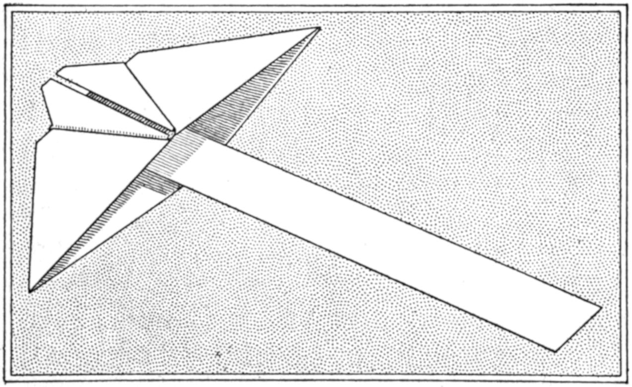
This Model Monoplane is Made of a Sheet of Paper, Seven Inches Square, and can be Steered by Bending or Twisting the Tail
To make this model, fold a square of medium-weight paper on the dotted lines, as indicated in Fig. 1 in the diagram. Then unfold the sheet and refold it as in Fig. 2. Then bring the folded corners A and B into position, as shown at A and B in Fig. 3. Fold the corners C and D upward to the position C and D in Fig. 4. Fold corners G and H to the corresponding letters in Fig. 5. Fold points J and K to the corresponding letters in Fig. 6. Raise the points J and K, Fig. 6, and fold them in so that the corners which were below them in Fig. 6 now come above them, as at L and M in Fig. 7. Fold the corner N back along the line OP, Fig. 8, so that the shape of the main portion of the model is as shown in Fig. 9, at OP. Make the tail 1¹⁄₂ by 14 in. long, as shown in Fig. 10, and paste it into position. This completes the model, which can be steered by bending or twisting the tail.—George H. Stipp.
Now that everyone should economize, short lead pencils should receive attention. A convenient lengthener is easily made by removing the metal ends from used film-camera spools, the 3¹⁄₄-in. length being the best size to use. The pencil is cut to fit the unslotted end of the spindle tightly. An eraser may be fitted in the slotted end. In a school quite a saving was made by collecting the short pencils of the pupils and having them thus fitted up in the workshop.—A. T. Moss, Napa, Calif.
[171]
Difficulty in the operation of a lawn mower is often caused by failure to use the machine properly. A lawn mower cuts like scissors except that one of the members is fixed. The cutters pass over the cutting bar at an angle and thus shear off the grass. The machine tends to throw the grass off to one side, usually toward the left; hence the machine should not be permitted to throw the cut grass back into the uncut patch. This may be prevented by passing around the lawn so that the uncut grass is at the right of the operator.—W. H. Kruse, Fort Wayne, Ind.
A simple substitute for the somewhat complicated telegraph recorders of the inking type may be constructed of materials readily available to a boy. The instrument shown in the sketch was made in a short time and with no special outlay. The base and the upright support are of wood. The armature A was made of a strip cut from a tin box, and folded to a length of 4 in.
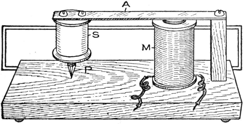
The Telegraph Recorder was Made of Materials That may be Gathered Easily by Boys
The recording device consists of a short piece of pencil, P, set in a spool, S. The electromagnet M is fixed to the base, and the armature A is actuated when current is permitted to pass through the magnet, causing the recording pencil to move vertically. A strip of paper is moved slowly under the pencil, and in order to make the record regular a small channel-shaped guide of metal may be arranged under the pencil.—William Warnecke, Jr., New York City.
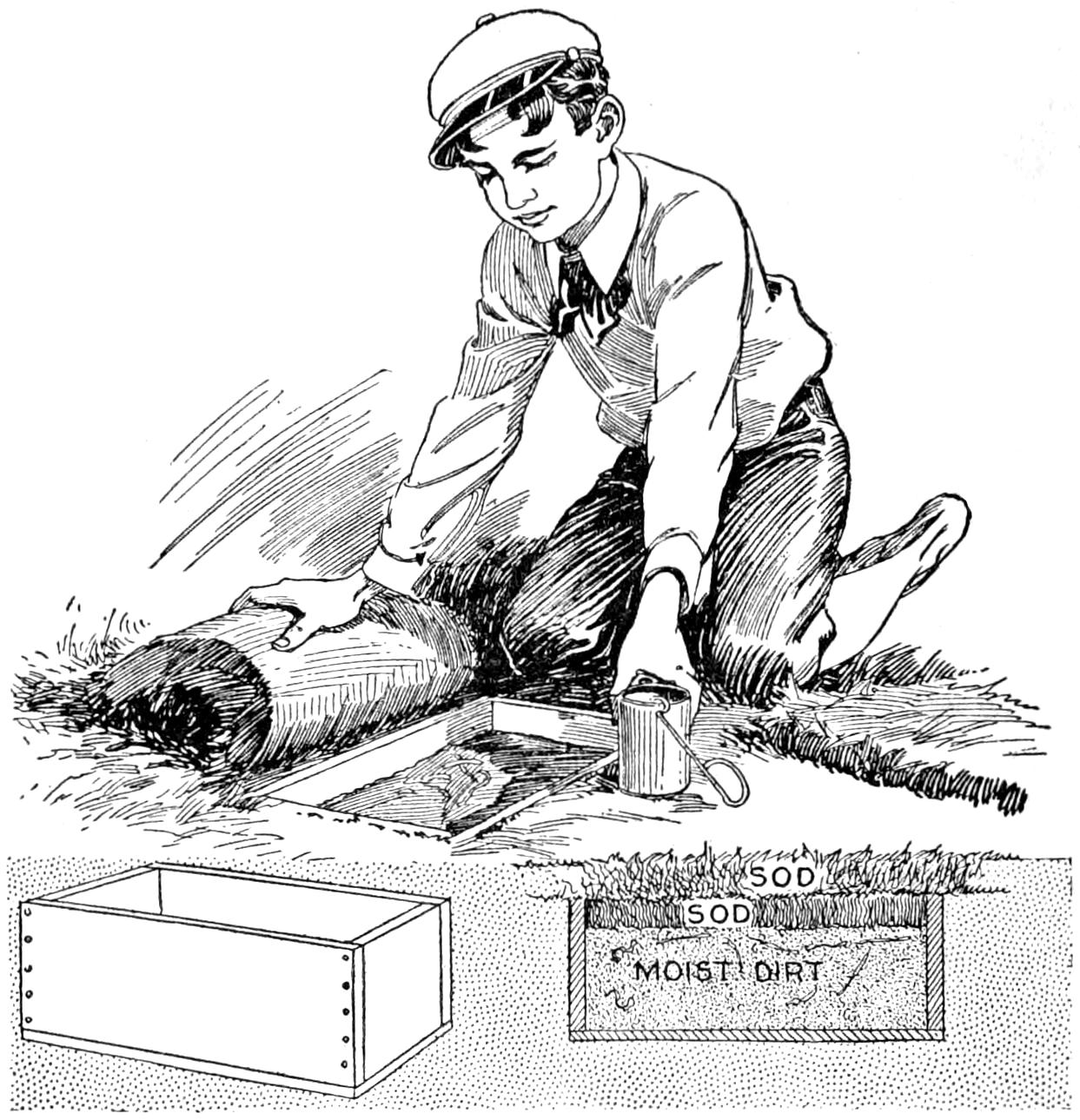
Angleworms for Fishing Bait may be Kept Satisfactorily in the Buried Box, Covered with Sod
Campers desiring a sure supply of angleworms for fishing will find the bait cache shown in the sketch convenient and practical. A box, about 18 in. long and 10 in. square on the end, is sunk into the ground in a shady place, and all the bait dug by the campers on their arrival is placed into it. The soil used to fill the box should be rich, black loam, quite moist but not wet enough to be sticky. A few inches of the top of the box is left unfilled and a double layer of green sod is fitted over it, as shown in the sectional view at the right. The upper sod is arranged level with the surface of the ground and should be cut carefully so that it will not be observed by prowlers. If the region where fishing is to be done is such that angleworms cannot be obtained easily, it is best to dig them before starting for the camp. The bait cache may then be made as a convenient place in which to keep the bait in good condition for fishing.
¶After cleaning a shotgun, or a rifle, a cork large enough to be seen readily should be placed in the end of the barrel to prevent rusting. The cork should not be pressed into the end deeply as, if it is forgotten and the firearm discharged without removing it, a dangerous explosion may result.
[172]
Ample power for driving light machines in a repair shop was obtained by the use of a wind motor like that shown in the sketch and in the detail drawings. The device has numerous other applications, particularly as a substitute for wind motors that require a high tower, as in the driving of a pump. As an interesting and inexpensive means of providing power for a home or boy’s workshop, or as an experimental device, the motor is also worth while making. The materials used are easily obtainable, and the construction can be carried out with ordinary tools, for the most part. The driving connections may be obtained from old machine parts. The dimensions given are for a motor of considerable size, and may, of course, be reduced proportionately for a lighter machine. If the device is made by boys, the framework and other parts should be made one-half as large as the sizes indicated. The wood used should then be three-fourths as thick as that shown. The roof of the structure upon which the device is mounted must be well braced and strong enough to stand the strain. The sails are headed toward the wind, like those on a sailboat, when the motor is at rest, by means of a control rod, F, shown in the working drawing.
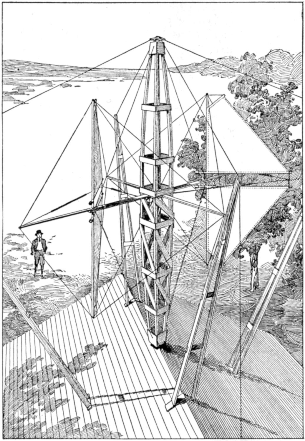
The Novel Wind Motor Developed Power for the Driving of Machines in a Repair Shop, and can be Made in Various Sizes for Work or Play Purposes
The main structural portion is a vertical beam, or tower, tapered at the ends and built up of 1 by 1-in. rods, strongly braced, especially in the lower portion, as indicated. It is 14 ft. high, and built around an 18-in. square board, A, notched at the corners to receive the posts. A similar 14-in. square, B, is built into the lower portion. The lower end of the tower is pivoted on the ridge of the roof on a hollow shaft made from a section of iron pipe, D, and provided with a metal bearing washer, E. The pipe D is split at its upper end, as shown in detail, and fastened to the wooden plate B. The control rod F passes up through the pipe D, and is fixed to the control wires, reaching the sails, by means of a leather strap, from which an iron swivel, C, is suspended, as shown in the detail at the left. The ends of the strap pass over pulleys, fixed to the lower side of the plate A, and connect with the sail-control wires. Spiral wire springs are attached to the wire connected to each end of the strap, as shown only at the right sail beam, and aid in controlling[173] the sails. These springs are adjusted so that when the control rod is drawn down to its lowest extent, the sails will be with the edge “into the wind,” thus neutralizing each other, and causing the sail beam to be at rest.
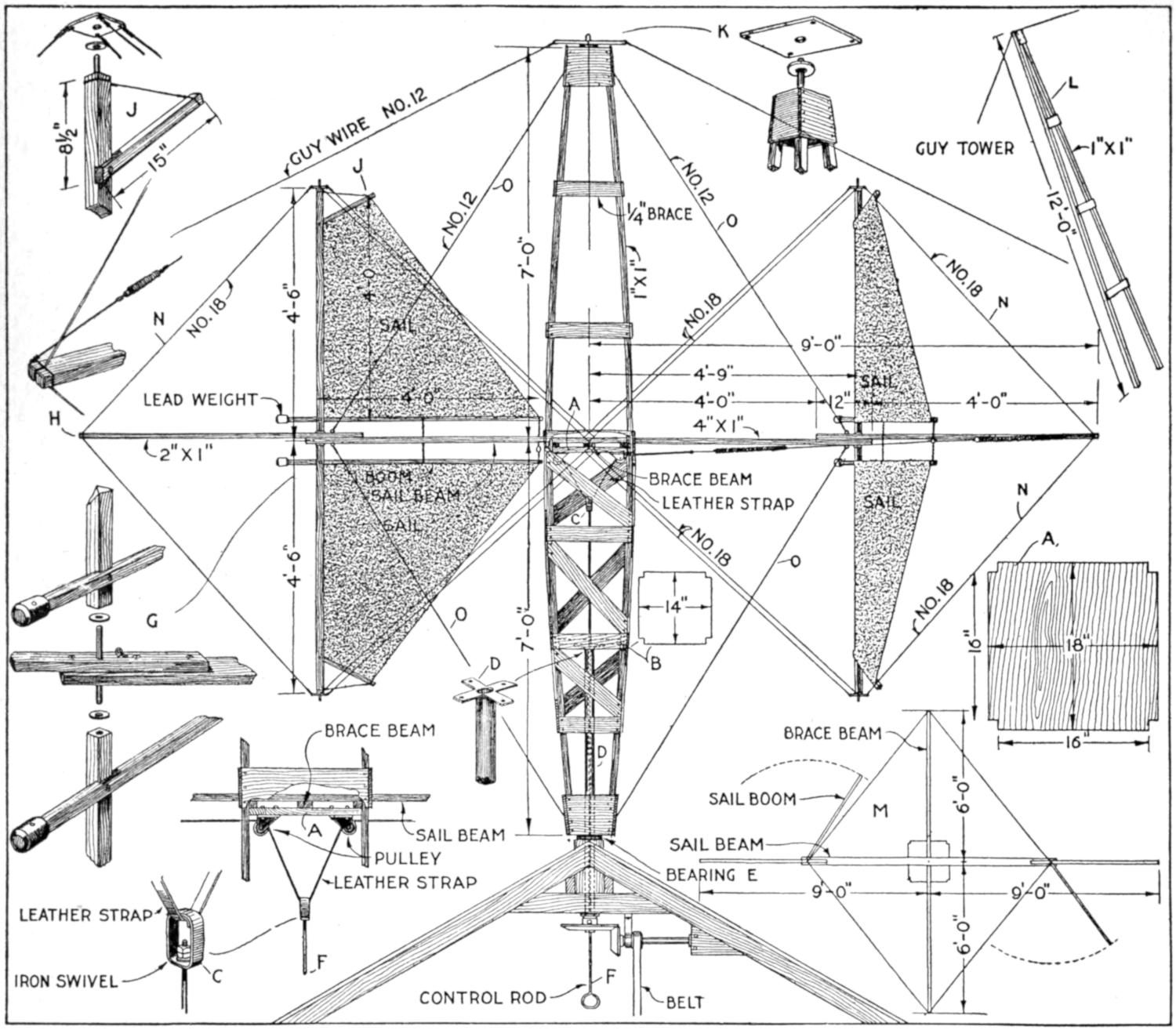
The Method of Construction is Shown in Detail: By Using the Perspective Sketch in Connection with These Working Drawings, the Arrangement of the Parts is Readily Understood
The sail beam extends 9 ft. out from the center of the tower, and is built up of three pieces. The center section extends through the tower, above the plate A, and the brace beam, which crosses it at right angles, as shown in the perspective sketch, and also at the detail of the strap arrangement. The center section is of 1 by 4-in. stock, and the end portions are of 1 by 2-in. stuff, fastened securely, as shown at detail G. The sails are supported on masts, 1 in. square, pivoted at their junctions with the sail beam, as shown at detail G, and in guy-wire plates at their extreme ends, as shown at detail J. The fastening and bracing of the gaffs at the mast ends is also shown at J.
The canvas sails are 4 by 4 ft., and mounted on the booms, gaffs, and masts. The ends of the booms nearest the masts are weighted with lead, as shown at detail G, and extend beyond the masts. The outer ends of the booms are joined in pairs, and connect to the spring and strap control. The guy wires N, of No. 18 wire, supporting the masts are fixed to the ends of the sail beam and to the ends of the brace beam, as shown in the sketch and the working drawing. The fastening at the ends of the sail beam is made as shown at detail H, which also shows[174] one of the coil springs. All of the braces for the masts should be fitted carefully, so as to have the proper tension without interfering with the action of the sails, before the tower is set into its place. The device should be tested on the ground, with the pivot shaft set in a suitable support, before attempting to mount it on a roof, or other structure. The support for the bearing should be fitted into the roof, as shown. The power from the shaft is transmitted to the bevel gears, and from them to the drive shaft and the belted pulley.
The main tower is supported on the roof by means of strong guy wires, set over four built-up guy towers of 1 by 1-in. wood, and 12 ft. long, as shown in detail L. The towers must be set so that the sail beam has proper play and be secured firmly to the roof. The top of the main tower is fixed to the guy wires by means of a guy plate shown in detail K. A plan of the arrangement of the sail beam, brace beam, and sail booms is shown at detail M. The sail beam is braced by No. 12 guy wires, O, attached at the top of the main tower, at the junction of the two sections of the beam, and similarly at the bottom of the main tower. The fastenings of the wires and braces should be made carefully, and they should be examined thoroughly both before and after the device is mounted in place. Grease the pivoted and other moving parts, and start the device slowly, bringing the sails into the wind as required for the desired speed.
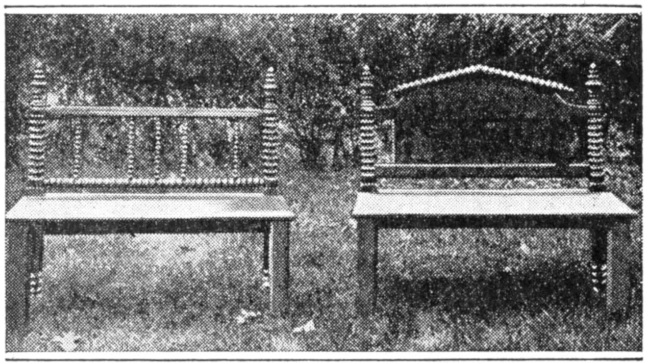
Painted Green, These Rebuilt Bedsteads Served as Lawn Benches
Old bedsteads were converted into serviceable lawn, or porch, benches, as shown in the photograph reproduced, by the addition of a suitable seat, properly supported. The transformation was a simple one. Only the foot and headpieces of the bedsteads were used. The front legs and other pieces were made from other wood. The front legs are of square stock, about 2¹⁄₂ by 2¹⁄₂ in. The crosspieces, supporting the wide board seats, are mortised into the legs and fastened with glue and screws. The seat is fastened from the under side by cleats. The lumber was carefully planed and sandpapered so that the benches presented a smooth finish when painted green, to match other outdoor furniture.—F. E. Tuck, Nevada City, Calif.
Wood-wind instruments sometimes “leak” at the joints or keys and make playing of the instrument difficult. Many such instruments are made in sections, with ends that telescope to form a tight fit. This fit is maintained by the use of a cork band cemented around the tenon end of the telescoping joint. The renewal of these cork joints, and the addition of new pads on the keys, will make an old instrument nearly as good as it was when new, so far as playing is concerned, provided the work is correctly done and the wood of the sections themselves has not cracked. Many musicians have spare time and can do this work themselves. The outlay for materials for the job is from 75 cents to $1.00. A small alcohol, or even a kerosene, lamp and an old knife, or old file, are required.
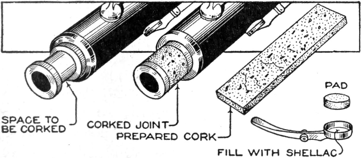
The Cork is Fitted Carefully into Place, and Glued
All traces of the old cork on the joint can be removed with sandpaper, leaving it as shown at the left. The cork comes in strips of about the proper thickness, and wide and long enough to allow for trimming. The ends of the[175] strip should be beveled to make a ¹⁄₄-in. lap joint.
A small quantity of the cement is heated over the lamp and six drops poured on the joint; then with the end of the file, which should be heated also, it is spread to give an even, thin coating. The beveled ends of the strip are similarly treated. By working quickly and carefully, the coating on the joint and strip are brought to a plastic state by holding in the flame, and the strip is quickly laid in place. Before the cement has time to harden, press the cork in, forming a neat joint. Bind a rag around the cork, leaving it until the cement is thoroughly set.
The corked joint will be too large to go into the joining section of the instrument. File and sandpaper it to a twisting fit. Though the cork should be truly cylindrical, it may be tapered a trifle smaller at the forward end. A coating of tallow applied to the joint will make it easy-fitting, but air-tight and moisture-proof.
The pads are disks of felt incased in thin sheepskin. After long usage, they become too hard to make an air-tight fit. Repadding should, therefore, be anticipated. Shellac will give good results in putting on pads. It is heated until liquid and poured into the key recess. The new pad is pressed into the liquid shellac, care being taken to have it well centered. For different keys, it will be necessary to use varying quantities of shellac to make the pad sit higher or lower, as required.—Donald A. Hampson, Middletown, N. Y.
¶A simple method of bracing a screen door is to stretch a stout wire diagonally across the lower portion of it.
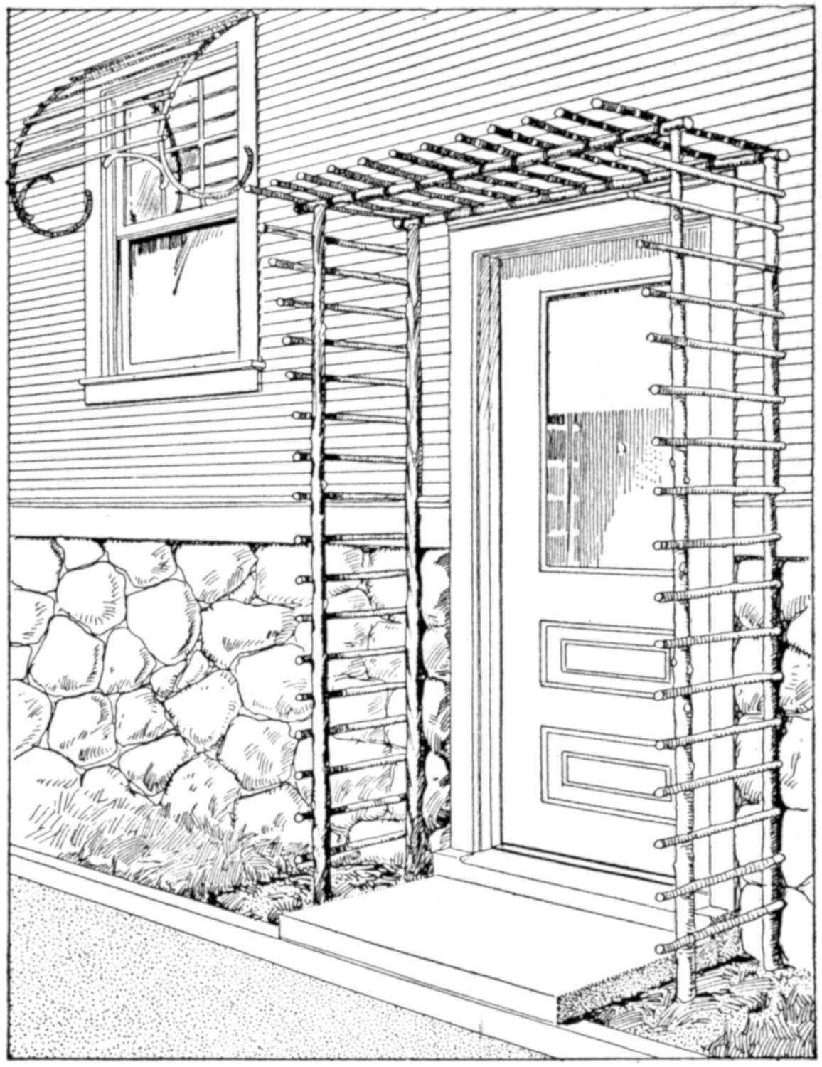
Rustic Trellises are Easily Constructed and When Covered with Vines Add to the Attractiveness of the Home
Proper preparation in the early spring will make it possible for the householder to shade doors and windows from the hot summer’s sun by means of inexpensive rustic trellises that add not a little to the beauty of the home. A suggestion for a trellis at a doorway and one for a window are shown in the illustration. They are made of straight tree trunks and small limbs, having the bark on them. The curved portions of the window trellis may be made easily by using twigs that are somewhat green. Morning-glories, or other suitable climbing plants, may be trained over the trellises.—J. G. Allshouse, Avonmore, Pa.
For reducing or enlarging maps, and similar drawings of irregular design, the device shown in the illustration will replace the ordinary instruments, and enable the draftsman to turn out a[176] given amount of work in much less time than required when proportional dividers are used. The materials needed are an eraser, a rubber band, two pins, two thumb tacks, and a few drops of rubber cement. From the eraser two pieces are cut, as shown in the sketch, about ¹⁄₄ by ¹⁄₂ by 1¹⁄₄ in. Cut deep slits in each end of these pieces. Insert the end of the rubber band, cut at the splice, in one of these slits and place a thumb tack in the other. A pin is thrust through the eraser and trimmed close, to prevent the thumb tack from tearing the eraser. Cement the slits with rubber cement, and place the assembled device under a book weight, until the cement has set.
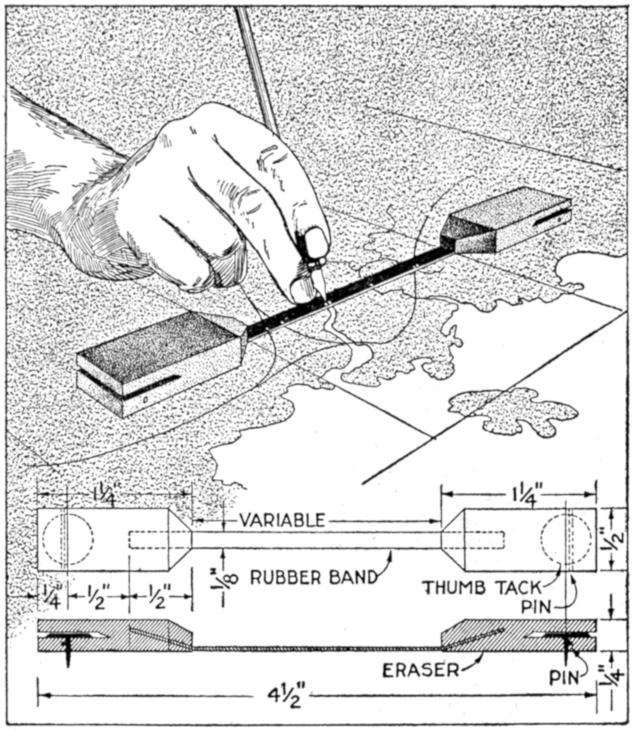
This Simple Device Is Useful in Enlarging or Reducing Drawings and Maps
Assuming that a contour map is to be enlarged, the rectangular divisions of the original map, ordinarily section lines or the boundaries of quarter sections, are drawn on the larger sheet as a base for the reproduction. Place the device on the original map, as indicated, the edge of the rubber band touching a “horizontal” section line between two “vertical” ones, the rubber band under slight tension. On the black surface of the band, dot white points, with water color, along the section line at which the contour lines intersect it. Also place a dot at each end of the band to indicate the position of the two “vertical” section lines between which the band is set.
Transfer the device to the same relative position on the enlargement, stretching the rubber band. Make dots at each end, denoting the “vertical” section lines, for the corresponding lines on the enlargement. The series of intermediate points along the band will be in the same relative position on the enlargement as they were on the original. They can be connected on the enlargement with as accurate a result as obtained by the use of proportional dividers, and more rapidly.
After the points are indicated upon the enlargement, the reproducing device is removed and the surface of the rubber band cleaned instantly by touching it with a moist cloth. The exposed part of the rubber band is a variable, and the device can be made with this dimension adapted to the work. It is capable of enlarging or reducing at a ratio not greater than six to one, above which the rubber band approaches its elastic limit.—H. L. Wiley, Seattle, Wash.
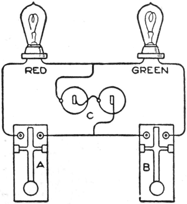
By arranging a circuit with batteries, lights, and keys, as shown in the diagram, a signal telegraph may be made that will afford much pleasure to boys and may be used for practical purposes. The keys A and B are wired into the circuit with a battery C and a red and a green incandescent lamp. A simple set of signals may be devised easily so that messages may be sent in the code.—James R. Townsend, Itasca, Texas.
[177]
While on the farm I constructed a circular swing which proved very attractive to my boys and their friends. By its side, and suspended from the same tree branch, was an ordinary swing. During the eight weeks of our stay the latter was seldom in use. The circular swing was a far greater favorite with all the young people, boys and girls alike.
Around a branch of a large elm and 18 or 20 ft. from the tree trunk was looped a 10-ft. length of chain and to the hanging end of this was made fast a 1-in. rope nearly 10 ft. longer than was needed to reach the ground. Directly beneath the point where the chain went around the limb, as determined by a plumb bob, was set a 6-in. piece of cedar post 3¹⁄₂ ft. into the ground. This was sawed off square 2¹⁄₂ ft. above the ground. Into the top of this post was set a ¹⁄₂-in. rod, to serve as a pivot for the swing. It was set in firmly about 6 in. and projected about 3 in. from the top of the post.
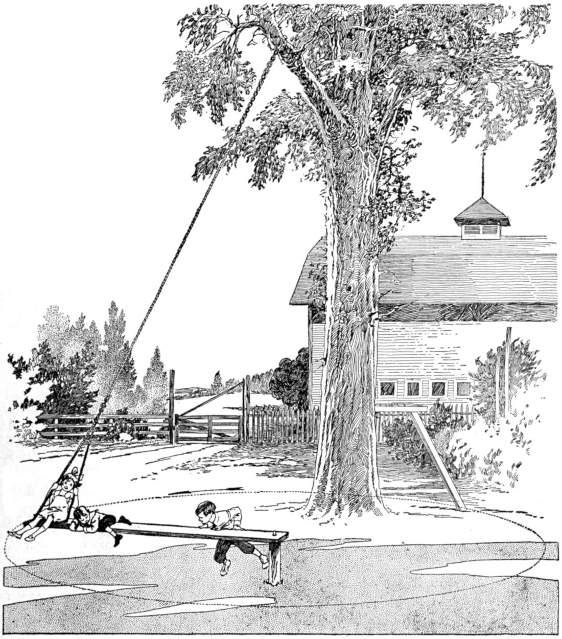
The Circular Swing will be Found Very Safe and Pleasurable, but, as is the Case of an Ordinary Swing, Anyone Careless Enough to Get in the Way of It will Get Badly Bumped
[178]
A straight-grained piece of pine board, 15 ft. long, 8 in. wide, and 1 in. thick, was procured and a hole bored in one end large enough to make it turn freely on the pin in the upper end of the post. Two holes were bored in the other end of the board large enough to admit the rope. The first hole was 6 in. from the end, and the second hole, 3 ft. The hanging end of the rope was passed down through one of these holes and back up through the other and then made fast to itself about 3 ft. above the board after the board had been adjusted so that it would swing throughout its length at the height of the post, or 2¹⁄₂ ft. from the ground. The swing was then complete except for a swivel, which was put in the rope within easy reach of one standing on the board, so that it could be oiled.
One good push would send the board with a boy on the end three or four times about the 90-ft. circle. The little fellows would like to get hold of the board in near the post and shove it around. Once started, it could be kept going with very little effort.
In putting up such a swing, make sure to have the post set solidly in the ground, as it has a tendency to work loose. Tie all the knots tightly. Do not look upon the swivel as unnecessary. The first swing I put up was without one, and the rope twisted off in a few days.
It is not necessary to climb a tree; just throw a stout cord over the limb by means of a stone or nut tied to the end, then haul the rope and chain up over the limb with the cord. Before the chain leaves the ground loop the end of it and pass the cord through the loop. The higher the limb from the ground the better the swing will work, but 25 ft. will be about right.
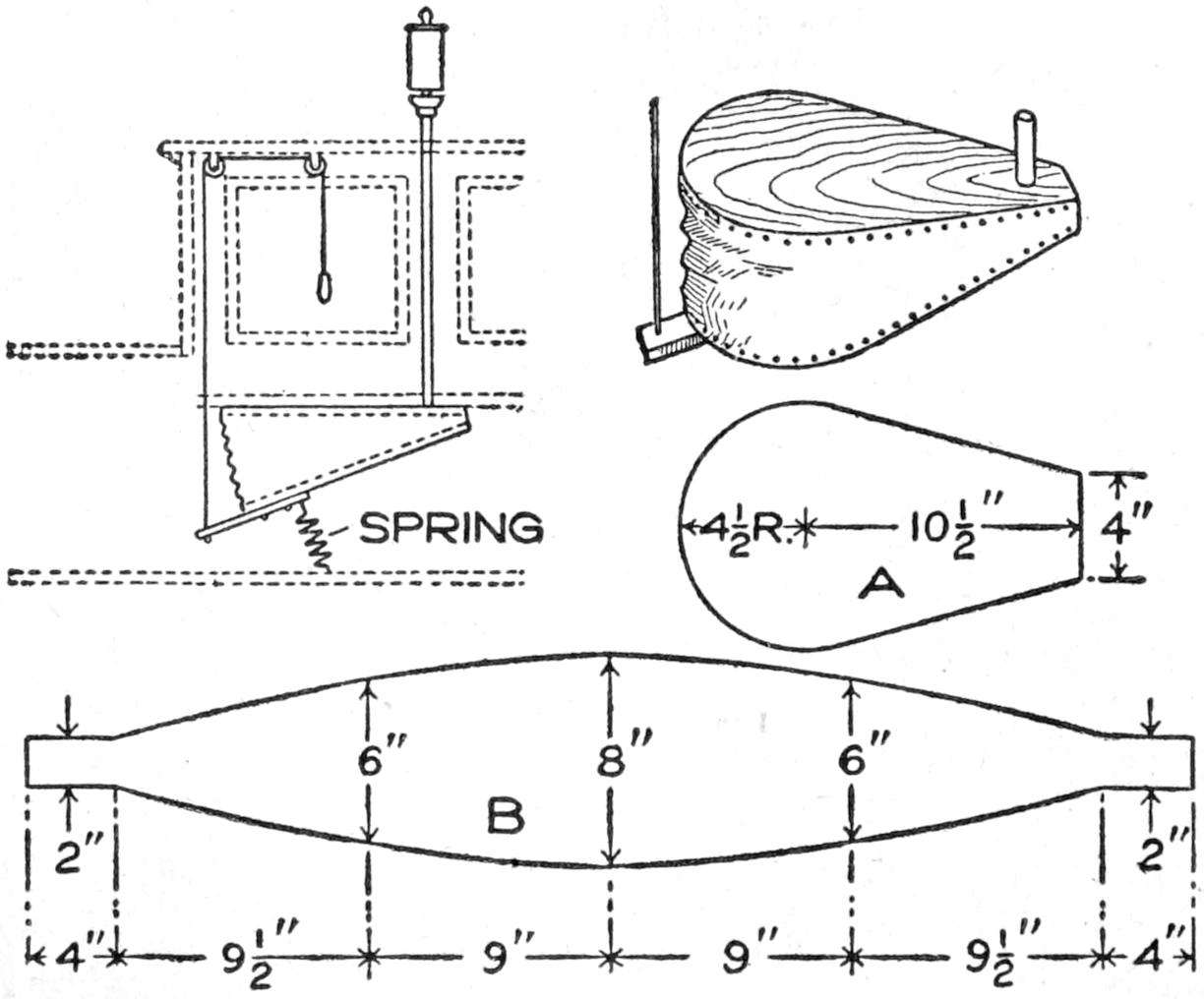
Bellows Operated by Hand for Blowing a Whistle on a Power Boat
Anyone with a power boat can construct a blower for the whistle very cheaply. The whistle is attached to a suitable length of pipe, threaded on each end. The blower is made of two white-pine boards, 1 in. thick, cut as shown at A; a thin piece of leather is cut like the pattern B, to form the bellows part, and after it is shaped, the edges of the boards are glued and the leather placed in position, where it is fastened with tacks driven in about 1 in. apart. The bellows are fastened to the under side of a seat with screws, and a tension spring is attached to the bottom of the bellows and the floor of the boat. A cord is fastened to the lower board of the bellows and run up through to the cabin roof over suitable pulleys to a handle within convenient reach of the operator.—Contributed by John I. Somers, Pleasantville, N. J.
Ordinary putty will not do to fill in cracks or broken spots on an enameled surface, such as a clockface. Fine sealing wax is much better, as it hardens at once, takes color without absorbing the oil, and does not shrink like putty. Use a wax of the proper color to match the surface as closely as possible. Fit it in and smooth with a warm, flexible piece of metal, such as a palette knife. Give it one or two coats of thin color to exactly match the other surface, and varnish. If the article has not a high polish, the gloss of the varnish can be cut a little with pumice stone.
[179]

“Step right up; three twisting thrillers for a penny—a tenth of a dime!” was the familiar invitation which attracted customers to the delights of a homemade merry-go-round of novel design. The patrons were not disappointed, but came back for more. The power for the whirling thriller is produced by the heavy, twisted rope, suspended from the limb of a tree, or other suitable support. The rope is cranked up by means of the notched disk A, grasped at the handle B, the car being lifted off. The thriller is stopped when the brakeplate I rests on the weighted box L.
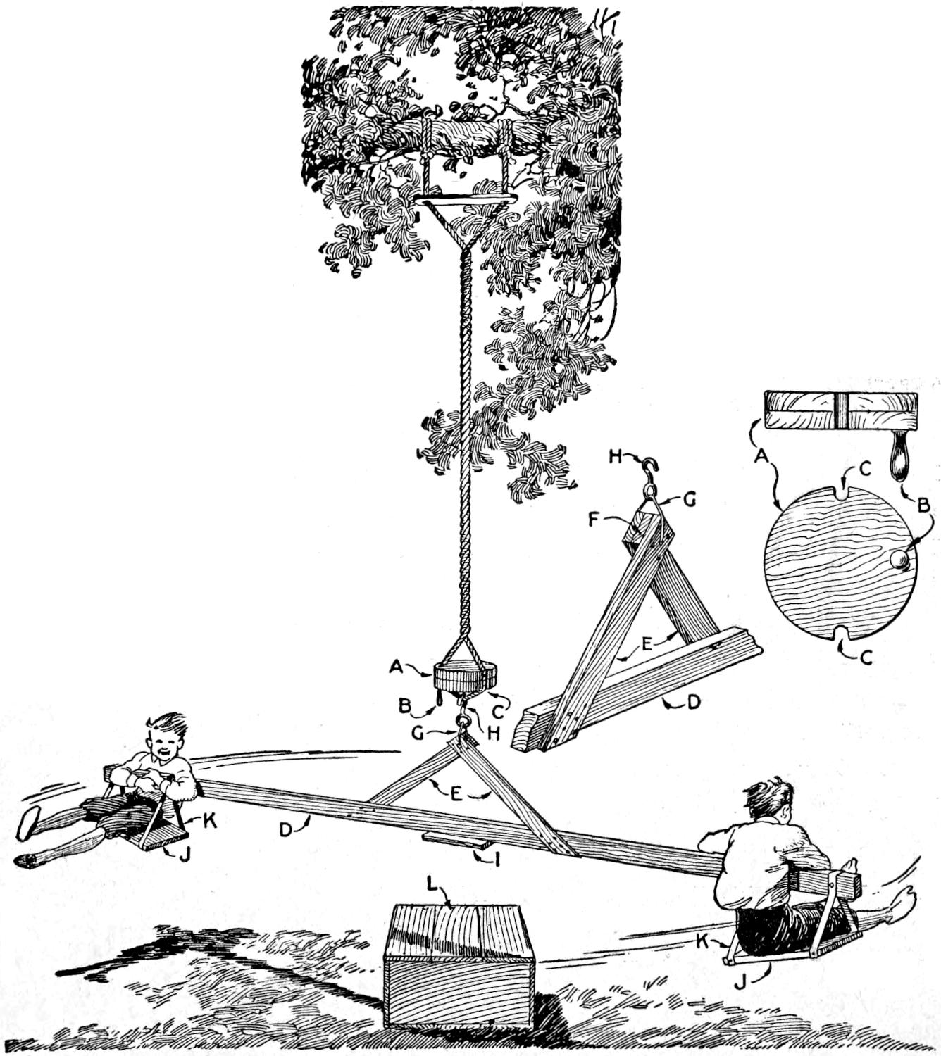
The Supporting Ropes are Wound Up at the Disk A, the Car is Hooked into Place, and the Passengers Take Their Seats for a Thrilling Ride, Until the Brakeplate I Rests on the Box
Manila rope, ³⁄₄ in. or more in diameter, is used for the support, and is rigged with a spreader, about 2 ft. long, at the top, as shown. The disk is built up of wood, as detailed, and notches, C, provided for the ropes. The rope is wound up and the car is suspended from it by the hook, which should be strong, and deep enough so that it cannot slip out, as indicated at H.
The car is made of a section of 2 by 4-in stuff, D, 10 ft. long, to which braces, E, of 1 by 4-in. stuff are fastened with nails or screws. The upper ends of the pieces E are blocked up with the centerpiece F, nailed securely, and the wire link G is fastened through the joint.
The seats J are suspended at the ends of the 2 by 4-in. bar, with their inner ends lower, as shown, to give a better seating when the thriller is in action. The seats are supported by rope or strap-iron brackets, K, set 15 in. apart. The box should be high enough so that the seats do not strike the ground.
When short of fiber needles or when the jewel needle has broken, file down the tooth of a bone comb to the required point, and it will serve well. If the needle arm becomes loosened from the diaphragm, and no wax is handy, a bit of soft chewing gum makes an excellent temporary repair. Use a[180] magnet to pick up steel needles from the receptacles on the machine, to save time and avoid punctured fingers. If the machine is too loud for the room, placing a piece of loose cotton in the tone arm, directly behind the reproducer, is more effective than muffling the sound at the horn end.—L. B. Robbins, Attleboro, Mass.
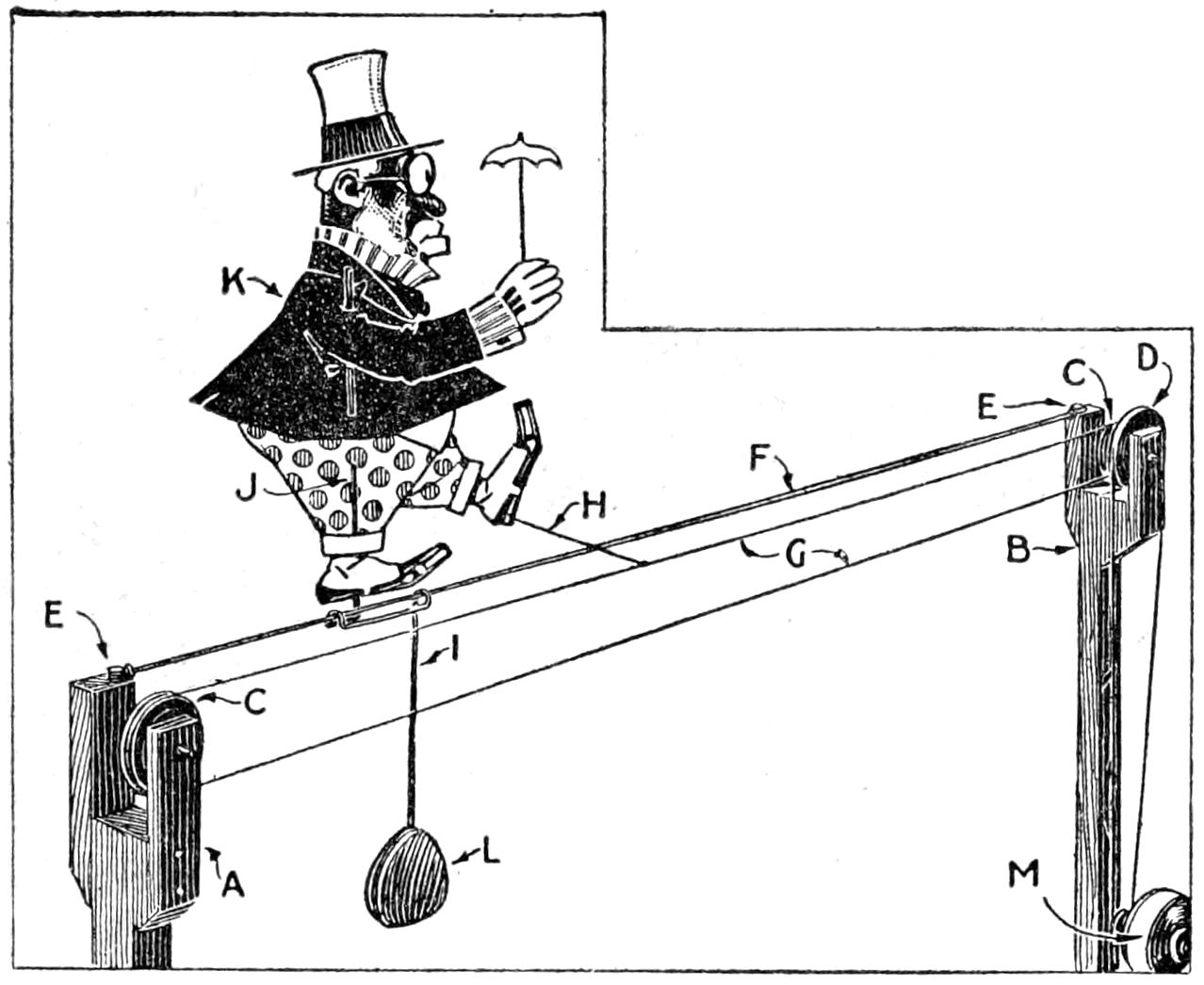
Adapted to Window Displays, This Amusing Toy Has an Advertising Value
A daring wire-walking performer who, unmindful of the fact that a misstep may mean destruction, keeps on going, back and forth, so long as the motor runs, or the crank is turned, is a toy that boys can make easily. The wire is stretched, not across Broadway, but between two 1 by 1-in. standards, held upright by guy cords, or fixed to a baseboard. They are fitted with forked tops, at A and B, and pulley wheels, C and D. A wire, F, is fastened to two of the prongs, at E, and a black thread, G, runs over the pulley wheels. A carriage, I, is formed from a 12-in. length of stiff wire, and weighted, at L, to balance upon the tight wire. The figure K is cut from stiff paper, and made to turn upon the carriage upright J, and braced with thread, at H. Thus the figure is always drawn forward, revolving on the support J at the end of each trip. Power to turn the thread is transmitted from a hand crank or motor, M, by means of the double pulley wheel at D.—Edward R. Smith, Walla Walla, Washington.
Having no native shade in our city chicken yard, we noticed one summer that the hens, especially those in the low brooder coops, became droopy and exhausted from the excessive heat. We studied the construction of the U. S. Weather Bureau thermometer shelter, which usually stands out in the sun, and is no larger than our brooder coops. It has a double roof with free air-circulation space between the roofs, hence the inclosed thermometers are exposed to a true-shade temperature. We then placed an extra roof on each of the brooder coops, leaving a 6-in. open air space between, the top roof being supported at the corners only. The arrangement proved so effective that the hens sought the coops, against the heat of unventilated inclosures on quiet, hot days.—J. Cecil Alter, Cheyenne, Wyo.
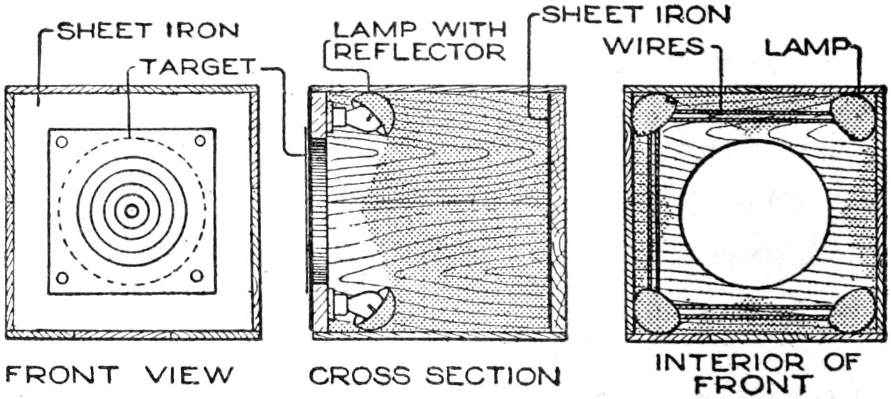
The Location of Hits is Recorded by a Beam of Light Streaming through the Hole Shot in the Paper Target
The joys of target practice are often hampered by the delays in the settlement of hits. It takes time and is annoying to be constantly advancing to the target to examine it. To do away with this, an illuminated target was constructed that enables the shooter to locate every hit without leaving his post. To make the device, a square wooden box of convenient size is obtained. In one side of this, cut a round hole as large as the largest ring on the targets used. The side opposite this is fitted with a piece of sheet iron to stop the bullets. Paint this iron and the interior white. Inside the box, arrange[181] four electric lights so their rays will be thrown on the hole, as shown. Candles may be used, if necessary. The lamps must be out of range of the bullets, that hit the target, and protected by an iron plate. The targets, painted on thin paper, are fastened over the front of the hole, and the lights are on, while shooting. Each shot punctures the paper, and the light streaming through the hole will show the location of the hit.—Thomas W. Benson, Philadelphia, Pa.
Photographic defects, spots, stains, etc., are often due to inadequate washing. In the common method of washing negatives or prints under the tap, in a dish, the water is not changed quickly enough. If the negatives are placed film downward and supported at the edges, the washing is quicker and more thorough. Films as well as glass negatives are in the same class in the matter of washing. Films should not stick together, and the sharp edges must not be permitted to cause scratches.
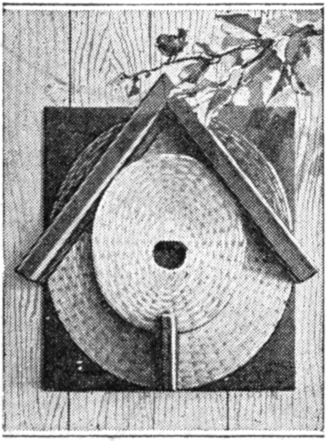
A bird house of an old straw hat is a practical and easily contrived affair. Cut a hole in the crown of the hat. Then nail the hat against a board of proper size. To protect the hat against the rain, put a roof over it, as shown. A perch is also provided. Such a bird house can be hung against the trunk of a tree, or nailed against a wall. Leaving the hat in its natural straw color, and painting the rest a dark brown, produces a satisfactory effect.—C. L. Meller, Fargo, N. D.
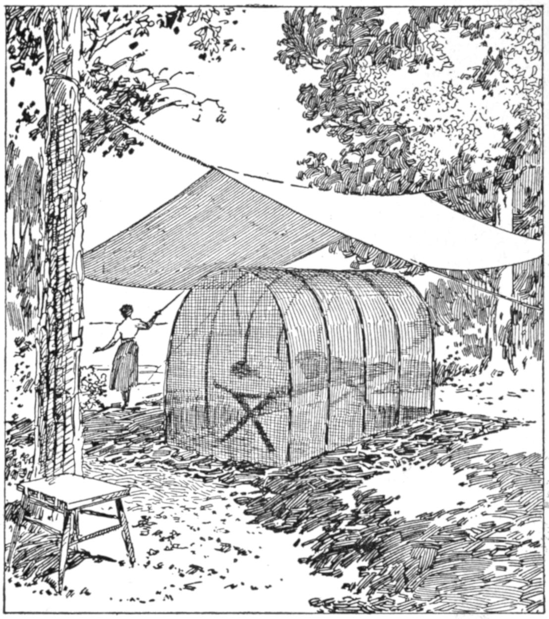
Lithe Branches Cut in the Woods are Used for the Framework, Which is Covered with Mosquito Netting
When it is undesirable to stay in a camping tent, on warm nights or during the day when a siesta is taken, a mosquito shelter can be made of materials readily available at most camping places. The arrangement, as shown, is made as follows: Procure a number of pliable switches, about ³⁄₄ in. in diameter, and 8 or 10 ft. long, willow or similar growths. Sharpen the butts, and force them into the ground in two rows, 3¹⁄₂ ft. apart. Bend the tops together, and tie them in arches of the same height, as indicated. Next, tie a ridge binder the entire length. Cover the frame with mosquito netting, providing an entrance at one end. The shelter shown is for one person, but may easily be made larger. The fly, supported on a rope between posts or trees, affords shade.—J. T. Trammell, Milwaukee, Wis.
¶The annoyance of a chair rocking on a bare floor, especially a child’s rocking chair, may be overcome by tacking sections of garden hose along the curved rockers. If properly done this also adds to the comfort of the chair.
[182]
A feature of a bazaar which attracted much attention was a rustic well from which a pretty girl dipped cool drinks with the aid of an “old oaken bucket.” The arrangement may also be used at an outdoor fair or lawn party.
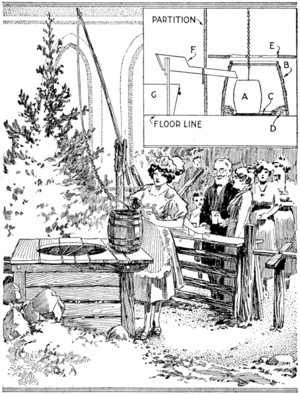
A Pretty Country Maid, Delicious Lemonade, a Peep into the Well, and Music from a Phonograph Were Attractions at This Booth
A corner of the room was marked off by a rail fence and turnstile. The floor was covered with green cloth and green excelsior, for grass. The well was constructed as shown in the detail sketch. Half of a barrel, B, with the head removed, was inverted, and a mirror, C, was set in a shallow pan of water on the floor. The pan was surrounded with pebbles, D, and a framework, E, built over the barrel. The supply of lemonade was kept cool in the tub G, behind the partition. When the bucket A was lowered into the well, by means of the sweep, it was filled by pouring the beverage in the trough F. The bucket was then raised and the drinks served from it, a cocoanut-shell dipper being used.
So many persons became curious to learn how the well was constructed, that an admission fee was charged to pass the turnstile, and the reward was a peep at the reflection in the mirror at the bottom of the well.—Susan E. W. Jocelyn, New Haven, Conn.
In printing pictures, I have made use of various masks, and those suited to the particular picture, for some special reason, have proved especially popular. For instance, in making a picture for a contractor and mason, a mask in the shape of a trowel was used; for a policeman, a star; an automobile for the motorist. Sometimes the special interests of persons in a picture, or the background, will suggest good outlines for masks.—Russell Waldo, Indianapolis, Ind.
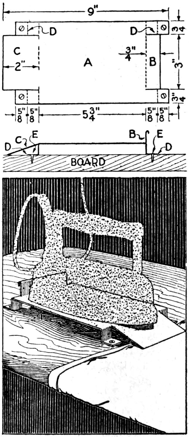
Considerable energy is consumed in lifting a heavy flatiron to the stand which protects the ironing board. The device shown in the illustration was made to overcome this objection to most flatiron stands and proved efficient as well as easy to make. The iron is shoved onto the stand at one end, provided with an incline. The layout for the sheet metal is shown in detail. The piece A is cut 4¹⁄₂ by 9 in., and the stop B, the incline C, and the leg D, are cut as shown, and bent to shape The stand is fastened near the end of the ironing board by means of screws.—Ernest Ward, Detroit, Mich.
[183]

Coasting down an incline and being projected through the air to plunge into the warm water of a summer lake, or other outdoor bathing spot, has thrills and excitement that appeal to the person seeking a new aquatic diversion. The illustration shows a slide, and the toboggan sled for use on it, that were built by a group of young men at a summer resort. While the slide shown is perhaps more extensive than most boys would care to undertake, the principle involved may be adapted easily to others one-fourth as long, less than 20 ft. The slide shown was strongly built of 2 by 4-in. material for the framework, 2 by 6-in. planks for the slide guides, and 2 by 12-in. planks for the bearing for the roller. Lighter material may be used for the guides and the roller bearing on a smaller slide, but the framework should be of 2 by 4-in. stock.
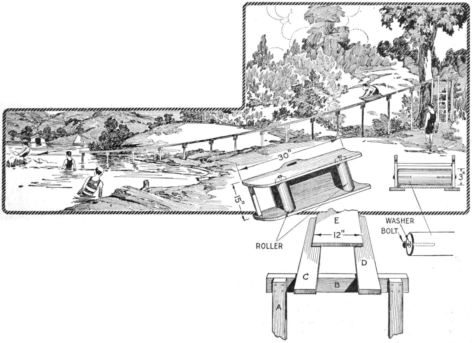
Thrills and Excitement That will Satisfy the Swimming Enthusiast and Provide a New Summer Diversion at the Lake or River may be Had from the Water Toboggan and Slide. It may be Adapted to a Smaller Size and Built by Boys. The Details of the Toboggan and the Construction of the Slide are Shown in the Sketches Above
The high end of the slide illustrated is about 7 ft. from the ground, but a proportionately greater incline is provided because the beach slopes gradually to the water’s edge. It is reached by a ladder fixed to a tree, which acts as an end brace for the slide. If no such natural support is available, the end of the slide must be strongly braced on three sides, to insure safety. It is inadvisable to build the slide unduly high to provide the necessary incline since this may result in accidents. A location where the ground is suitable should be selected rather than assume danger or risk.
The end of the slide nearest the water may be given a slight upward turn, so that when the toboggan leaves it the rider is carried upward before striking the water. The hold on the toboggan should be retained when entering the water, as injury may result by failure to clear it in the plunge.[184] With experience a dive may be made as the toboggan leaves the slide.
The construction of the slide is shown in detail in the lower sketch. The framework of 2 by 4-in. material should be only slightly wider than the guides, and the supports should be spread toward the ground to give rigidity. The supports A should be nailed firmly, or bolted, to the horizontal members B. If lighter stock is used, the pieces at B should be nailed in pairs, one on each side of the uprights. The guides C and D should be of smooth lumber, and the edges of these pieces, as well as of the bearing plank E, should be rounded off to remove splinters. The joints in the sections of the guides should be made carefully and placed over the framework supports. They should be reinforced from the lower side by plates of wood.
The bearing plank E is of 2-in. stock and 12 in. wide. It may be made of lighter material in a smaller slide. The joints in it should likewise be made carefully, to insure smooth riding over them. They should be set directly over the framework supports, but not on those over which joints have been made in the guides. The plank forming the bearing for the roller should not extend to the end of the slide at the lower end, but should be set back about 18 in. This permits the toboggan to slide off smoothly rather than to spring directly into the air from the bearing on the rollers. The bearing plank may be nailed into place, but care must be taken to set all nails below the surface. A better construction is to use screws or bolts. Bore holes for them through the plank, countersinking their heads.
The toboggan, as shown in the detail sketches, is built strongly, and is to be fitted over the 12-in. bearing plank, allowing ¹⁄₄-in. play on each side. The sides are of 1¹⁄₄-in. stock and high enough to accommodate the rollers, which should be about 3 in. in diameter. The dimensions of 15 in. in width and 30 in. in length, on the top surface, are suggestive only, and will vary with the materials used. The toboggan will not stand the necessarily hard wear unless good-quality oak, or other hard wood, is used. The top and foot brace should be fixed strongly with screws, their heads countersunk.
The rollers are fixed in the sides by means of screws, or a bolt may be set through the length of the roller. In either case the bearing should be in holes bored through the sidepieces. Washers should be fitted at the sides of the bearings, and the latter must be kept greased. All the edges and corners of the toboggan should be rounded off so that there is little possibility of injury from slivers or contact with the edges.
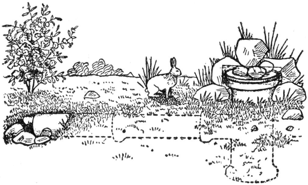
By Closing the Smaller Opening, the Rabbit may be Trapped and Removed at the Cover
Rabbits may be trapped in order to rid grounds of them, or for food purposes, by the use of the tile trap shown in the illustration. A tee, having a smaller opening of 6 in., is set in the ground with the large end projecting. Rocks are placed around it and it is provided with a cover. Several extensions are attached to the 6-in. opening and the end permitted to project slightly from the ground. Rocks are also placed about this opening. The rabbit enters the trap at the small opening and is free to come and go from the burrow. By closing the small opening, the quarry may be taken out at the large opening.
¶Vaseline is a good cleaner for commutators while machines are in operation and under load.
[185]

Making a raft for crossing a stream, or other small body of water, is often a diversion for campers, who have the usual supply of camp tools and materials. The woodsman is sometimes confronted with a different situation: He has only a hand ax as his tool equipment, and to construct a fairly safe raft of crude materials becomes necessary in order to pursue his course. Logs are readily available, and he may be fortunate enough to find willow withes, various stringy kinds of bark, or even coarse seaweed. If these are not available, the practical woodsman, particularly of the northern regions, builds a raft of logs, pinned together firmly with poles and pointed wooden spikes, cut on the spot. The method, as shown in the illustration, is simple and interesting. It may be of service in the woods even when other methods of binding the logs into a raft are possible, and as a practical test of woodcraft for the amateur or boy camper it is of interest. The sketch shows the completed raft, bound together by wooden pins notched into[186] poles, and the inset details show the manner in which the poles are clamped by the crossed pins.
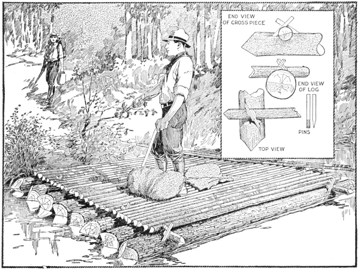
The Inventive Woodsman Builds His Log Raft of Simple Materials Gathered at the River Bank; the Logs and Poles are Notched Together Firmly and Held with Wooden Pins
This method of construction may be applied to a variety of rafts, for carrying small or large loads. In selecting the material for the raft several points must be considered. Dry logs are preferable to wet or green ones, and if the latter are used, a relatively larger raft will be needed to carry a certain load. For one passenger, three logs, 9 to 12 in. in diameter, 12 to 16 ft. long, and spaced to a width of 5 ft., will provide a stable raft. Poles may be laid across it to give sufficient footing. For heavier loads the logs should be about the same length and diameter, but spaced closer together, and laid to form a raft of considerable width and of greater buoyancy.
Select a shore, sloping gently into the water, if possible, and cut the logs and poles as near this place as is convenient. Cut the logs and roll, them to the bank, alternating the butts, if there is any considerable difference in the diameter of the ends. Cut a supply of poles of about 3-in. diameter, and of the length necessary to reach across the proposed raft. Then cut a number of pins of hard wood, 1 ft. long, and sharpened on one end, as shown in the detailed sketch.
Roll the first log—one of the largest—into the water until it is nearly floating. If it is bowed or crooked, place the “humped” side toward the outer edge of the raft. Chop notches, 2 in. deep, in the top of the log about 1¹⁄₂ ft. from the ends, and squarely across. Place a pole in the notch, with its end projecting slightly beyond the log, and cut a double notch in the upper edge of the pole, as shown in the detail sketches, so that when the pins are driven into the log, they will rest diagonally in the notches cut into the poles. Make rifts in the log with the ax, cutting as though to split off a slab of bark and wood, rather than toward the center of the log, and drive two of the pins into place. Properly done, this will make a remarkably strong joint. Fasten a second pole at the other end of the log, and prop up both poles so as to permit the next log to be rolled into the water, under the poles.
Notch the second log before slipping it finally into place. Alternate ends only, of the inner logs, need be fastened, and if time is important, some of the logs may be left unfastened, provided they are held tightly between the logs that are pinned. Shove the raft out into the water as each log is added. If there is a strong current it is desirable to guy the raft with a pole to the bank, downstream. The last log, which should also be a large one, is then floated down and pinned at both ends.
The raft may then be floated, and is ready to be covered with light poles or brush, to provide a dry footing and a place for the dunnage. The dunnage is placed near the forward end of the raft, and the person controlling it sculls with a pole at the rear.
Practically all of my negatives are of post-card size, and, in making bromide enlargements, I experienced difficulty in getting a satisfactory focus on 6 by 10-in. or 8 by 12-in. prints. When the center of the picture was in focus the outer portions were usually blurred, and vice versa. Compromising between the two gave unsatisfactory results. By providing a curved surface, on which the bromide paper is mounted, results were obtained that are satisfactory except for architectural subjects. A wooden box was made as long as the desired print and 1 in. wider. The height may be made as is convenient, but a height of about 2 in. is satisfactory. A partition was fitted into the box, dividing its length into two compartments. The upper edges of the center partition and the ends of the box were cut in the shape of an arc, the curve being determined[187] by the distance from the lens to the easel when the center of the picture is in focus. The bromide paper is fitted to the curves on the box. The device is fitted to the easel by means of two strips fixed to the bottom of the box, and extending beyond its ends. The curved surface may be covered with cardboard to give a better backing for the bromide paper, which is held in place by pins or small tacks. Where only a small portion of the negative is to be enlarged, this difficulty will not present itself, the flat surface being satisfactory.—Victor Woodland, Denver, Colo.
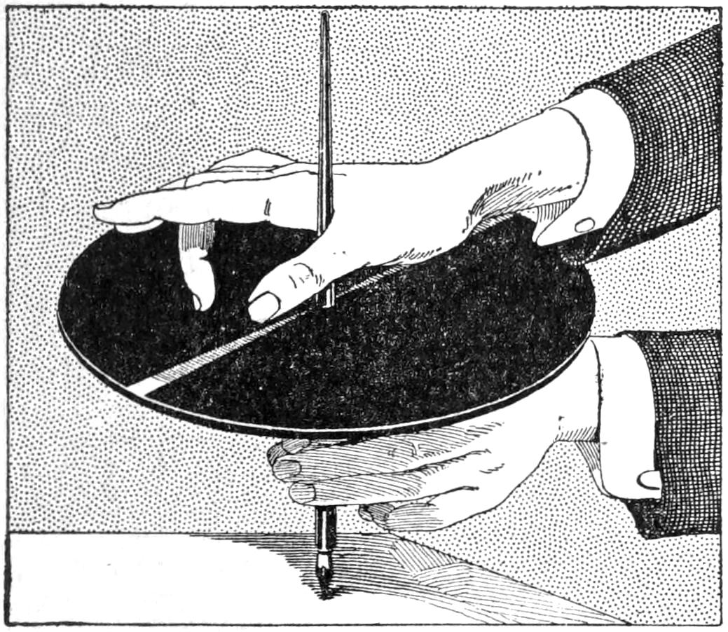
Talking-Machine Records may be Played with the Finger Nail after a Little Practice
Talking-machine records may be played with the finger nail, and a person skilled in the process can afford a party of spectators much amusement, creating no little surprise. The record is placed over a penholder, or pencil, and supported by the left hand as shown in the sketch. It is revolved by the fingers of the left hand, and the nail of the second finger of the right hand is applied to the record. Practice is required to obtain satisfactory results and an old record should be used.—George S. Nissen, Chicago, Ill.
¶Finely powdered graphite dusted on the parts of a motorcycle clutch when repacking it after cleaning will act as an excellent lubricant.
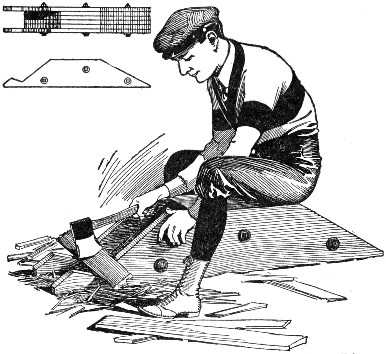
This Chopping Block Makes for Safety in That Pieces are Thrown Away from the Worker
Chopping of pieces of wood, which must be broken into short lengths, is often dangerous. The chopping block shown in the illustration was designed to overcome this element of danger and it may be used for chopping small kindling wood as well as for breaking up heavier pieces. When the blow is struck on the wood to be broken the pieces are thrown away from the person chopping. The sketch shows the device in use for the chopping of short pieces of wood, and the heavy portion may be used as a seat. The smaller sketch shows how the block is built up of 2-in. planks, bolted together—A. S. Thomas, Amherstburg, Canada.
A strong repair for a broken reed handle, like those on market baskets, handbags, or workbaskets, may be made by joining the broken parts with a ferrule of tinned sheet metal, brads or wire being used to prevent the ends from working loose. After the metal fitting has been made, the handle is rewound with the ends of the material unwound from it, or if desirable, the entire handle may be re-covered with material of the original kind or other suitable substitute.—R. E. Brown, Portland, Ore.
[188]
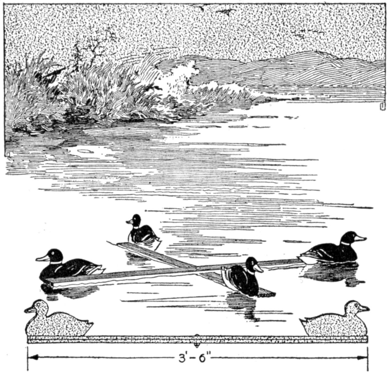
Duck Decoys Mounted on a Folding Frame may be Made by the Hunter
The duck hunter who wishes to economize by making some of his equipment will be interested in the folding frame for duck decoys, shown in the illustration. It is made of two strips, ³⁄₄ in. by 2 in. by 3 ft. 6 in., of soft wood, and fitted with a bolt at the middle, so that it may be folded, for convenience in carrying. The decoys are cut from a sheet of tinned metal, and are painted to resemble the game.—Carl A. Haberlein, McPherson, Kan.
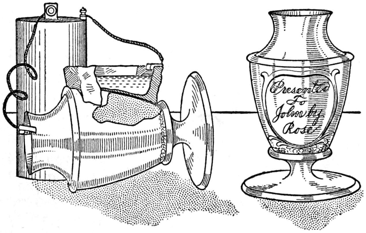
Copper or Other Metal may be Deposited on the Surface of the Cup, Making an Effective Inscription
A novel method of inscribing names or other indications on trophy cups or medallions is to onlay copper, or other contrasting metal, upon the surface by the process illustrated. Beeswax, or paraffin, is fixed to the side of the cup and formed into a dish shape, the surface on which the onlaying is to be done being covered with only a thin layer of the wax. With a needle or other suitable instrument, scratch the markings desired through the thin layer of wax to the surface of the cup. Pour copper sulphate into the wax cavity if the onlay is to be of copper, and suspend a small piece of pure copper in the liquid, connected with the positive pole of a storage battery, or other similar electrical source. Attach a wire from the negative pole of the battery to the cup. The copper will be deposited on the surface of the cup where the thin layer of wax has been scratched off, exposing the metal. The thickness of the deposit will depend on the length of time that the current is permitted to flow. Ten hours of action will permit the depositing of a satisfactory onlay.—M. H. Edwards.
Caution in the use of motorcycle tires with a minimum of abuse will result in a considerable tire saving. Tremendous wear on a single spot results when the power is thrown in so suddenly that the driving wheel makes several revolutions before gripping the ground. The proper air pressure must be maintained in the tires in order to obtain good wear. Guessing is a poor method of determining the air pressure and the exact condition should be noted from time to time with a gauge. Ordinarily, a pressure of 45 to 50 lb should be maintained in the rear tire and about 20 per cent less in the front tire, in the case of 3-in. tires. Rim cutting from running motorcycle tires underinflated is the commonest abuse. Dents in the edge of the rims cause undue wear on the tire, the fabric being worn through by the constant rubbing. Bent rims are often caused by insufficient air pressure in tires, the liability to injury being increased when crossing tracks or bumps with an improperly inflated tire.
[189]

Severe weather soon damages a tennis-court backstop that is built on posts set in the ground, and permitted to remain in place during the winter. The backstop shown in the illustration was designed to overcome this objection, and proved efficient on this score, as well as economical to build and maintain. Instead of setting the supports in the ground, they are set on the ground, and guyed by a system of wire braces. The wire netting is also held taut by wire braces, and the entire rigging is quickly taken down for storage, and easily set up when needed again. The lower edge of the wire is held down by hooks pinned to the ground with tent stakes, making it convenient to unhook the netting when the grass is to be cut around the backstop. The towers are 50 ft. apart, about 14 ft. high, and built up of 4 by 4-in. and 2 by 4-in. pieces of sound yellow-pine timber.
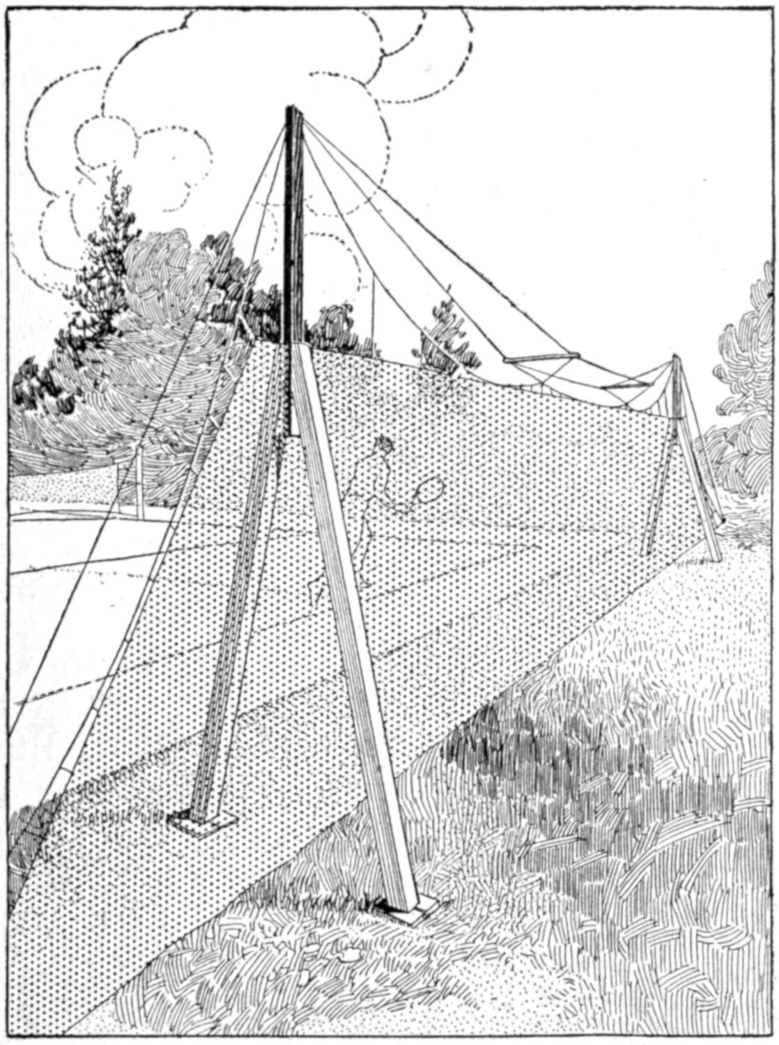
The Backstop is Taken Down between Seasons, and can be Raised Quickly by Means of the Supporting Cables
Foundations of brick, anchored into the ground, were made for the towers. End braces of heavy wire, fastened to the top, and guyed to the sunken anchors at the ground, support the towers against the weight of the netting and wire rigging. This is convenient in setting up the arrangement, as a ladder can be leaned against the end of the tower, guyed securely. To withstand side motion at the top edge of the netting, the supporting wires are carried on crossarms of 1 by 1-in. pieces of wood, 2 ft. long. This rigging is suspended between the towers and wired to the netting. When this is drawn up tightly, the netting is fairly taut. Additional supporting wires, with vertical leaders to the netting, are used to draw up the entire length of the netting tautly, as desired.
The netting extends under the towers, and is supported there by wires. As the netting extends nearly to the end guy wires, players cannot be harmed easily by running into the wires particularly if a white flag is attached to the guy wires, about 6 ft. from the ground. Number 20 gauge wire was used for the supporting cables, and No. 9 for the end braces extending to the anchored fastenings.
[190]
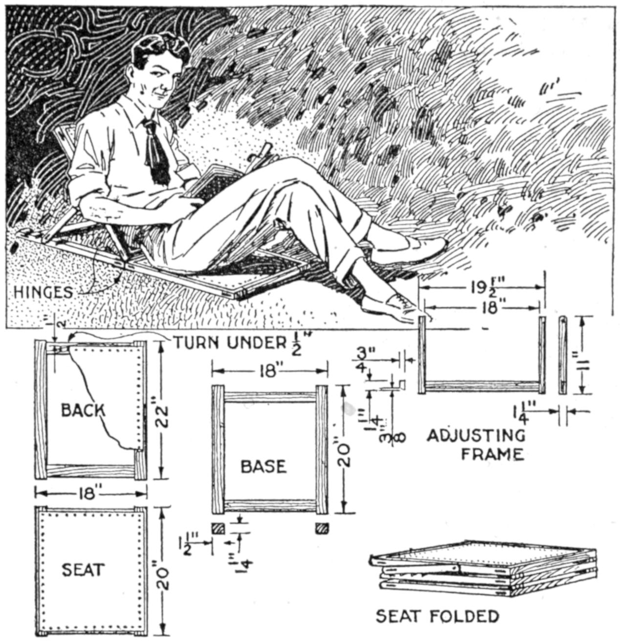
This Seat Is Useful Out of Doors and Also for Special Purposes Indoors
Those who enjoy sitting or lying upon the grass while reading will find the device shown in the illustration convenient and comfortable. With this, one may enjoy the coolness of the ground without harm to the person or clothing. The adjustable back rest supports the body in various positions. The device is light, compact, and readily transported. It is useful also in the home and elsewhere. By placing it across the bed, or on a trunk, a good substitute for an extra chair is provided. The seat proper may be folded under and the back rest used as a prop for reading in bed.
Oak is a suitable wood, and other common woods may be used. First construct, according to the dimensions given, three rectangular frames, with mortise-and-tenon joints. Cover the seat and back frames with heavy duck, turning it in ¹⁄₂ in. at the edges. The base is an open frame, provided with adjusting notches, spaced 2 in apart. Next make the adjusting frame, as detailed. Hinge the back and the seat to the base, and fasten the adjusting frame to the back with screws, permitting it to fold, as shown.—T. H. Linthicum, Annapolis, Md.
Steam yachts often carry a motorboat tender, and an automobile may carry a bicycle for emergencies. An autoist whose duties require him to travel through rural districts, had numerous unhappy experiences with a stalled car until he hit upon this scheme. The bicycle is strapped on the running board of the car, its handlebars turned flat against the side, and its wheels in tire sockets in the running board. A tank in the bicycle frame holds several gallons, and if the owner runs out of gasoline, he uses the tender to get a supply, filling the auto tank by siphoning the gasoline through a flexible tube.—John Miller Bonbright, Philadelphia, Pa.
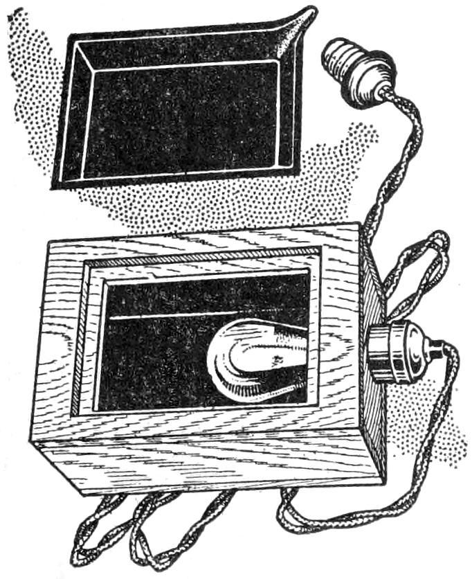
Having had trouble with developer cooling down and failing to work properly, while developing in the dark room, I constructed the apparatus shown. A small light-tight box was made slightly larger than the tray, with a removable top having an opening to hold the tray. An electric-light socket was fastened inside at one end of the box and a lamp fitted to it. A wire was attached across the middle of the lower side of the box, so that the latter and the tray could be rocked. The box was lined with black paper and varnished black. The edges of the opening in the top were fringed with felt to guard against light leakage. A thermometer is used to determine the temperature. When the developer cools, turn on the light until it reaches the required temperature.—John Hoeck, Alameda, California.
[191]

As an example of the application of steam power to the propulsion of a vehicle, the motorcycle shown in the illustration is interesting. While it does not embody the many refinements of gasoline motorcycles manufactured commercially, and makes no pretense of competing with them, the machine has a striking individuality. It was made by a mechanic in his spare time, with only the facilities of a small machine shop. Tests and hard usage over typical roads have shown it to be easy riding, partly by reason of its weight, and to give very steady power. The machine can be reversed quickly and no clutch is used. It has a wheel base of 75 in., and weighs about 350 pounds.
The upper portions of the frame are made of 1-in. steel tubing, strongly riveted at the fork and other joints. The lower section, from the fork to the rear axle, is made of a double bar of 1¹⁄₂ by ¹⁄₂-in. steel, spread and braced to carry the tank, engine, and boiler. The fork is forged from strips of steel, and fitted to standard motorcycle wheels. The handlebars, seat, transmission chains and gears, as well as other fittings, are of the ordinary motorcycle type. The seat may be moved and clamped at various places along the upper bar of the frame, and an extra seat may be installed, or a bundle carrier may be fitted behind the driver.
Gasoline, with which to heat water for the generation of steam, is carried in the long round tank, hung below the frame at the top. The water supply is contained in the square flat tank under the lower part of the frame. The engine is supported on the frame immediately above the water tank, and drives a shaft, which is geared to the rear wheel by a chain and sprocket.
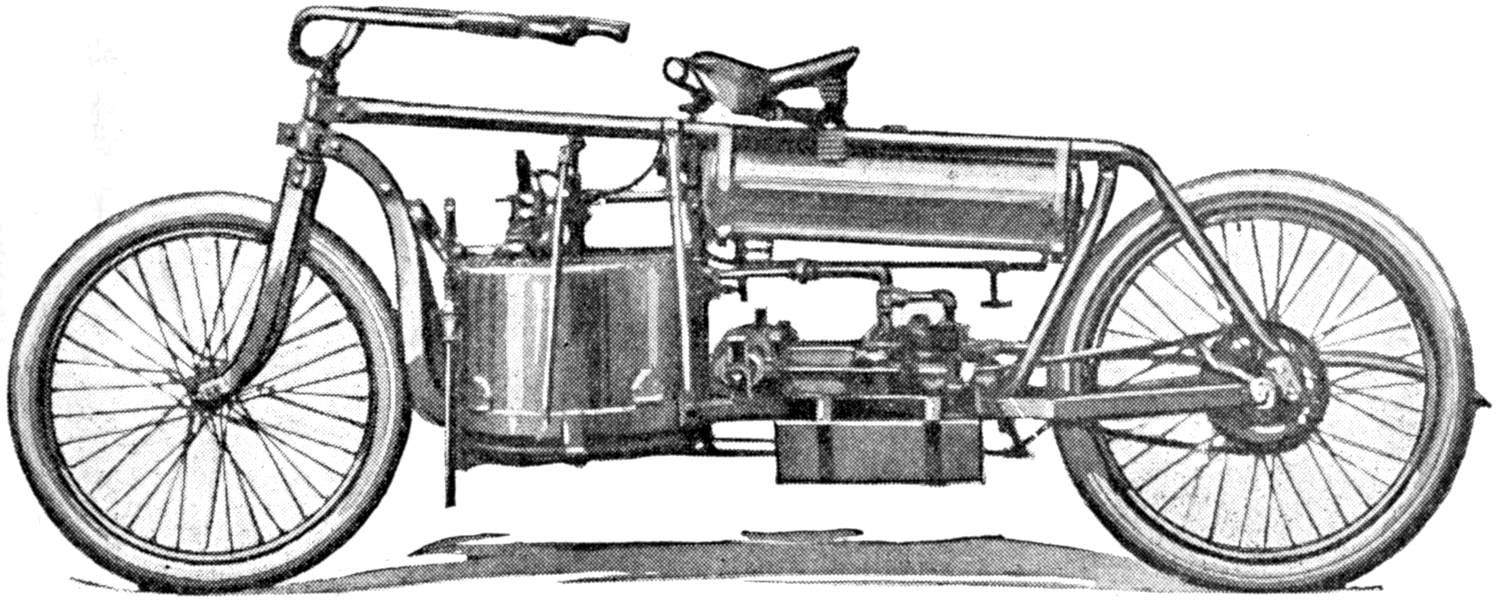
This Motorcycle is Propelled by a Steam Plant and was Built in a Small Shop by a Mechanic in His Spare Time
The round boiler, with gasoline burners beneath it, is carried on the lower part of the frame, which is spread, immediately behind the front wheel. The boiler is 16 in. in diameter and 12 in. high. It is fitted with valves, whistle, water gauge, and the usual fittings of a boiler. The engine is of the horizontal type, and the working parts are largely inclosed, so as to protect them from dust and to avoid possible danger to the operator.
[192]
Living in rooms, in which it was necessary to use the small living room as a kitchen and dining room as well, the storage of the cooking equipment became a problem. It was unsightly in the room when not in use, and there was no convenient place in which to store it out of sight. The kitchenette, shown in the sketch, was made from an old sideboard, and served the purpose admirably, being useful also for other needs.
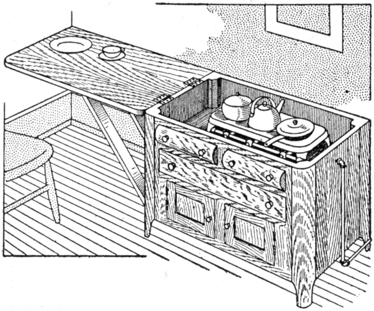
An Old Sideboard was Converted into a Useful Kitchenette, Which Economises Space
The top was removed and hinged to one end, the supports being removable, for storing them in the cabinet. The hinged top provided a support for the dishes while cooking. The partition between the top drawers was removed and the fronts of the drawers fastened in place with screws. The space thus made available was lined with asbestos, and a small gas stove was fitted into it. The gas line was connected to the stove and two pieces of asbestos sheeting were hinged to fold under the cover and to be leaned against the wall as a protection while cooking. The top could be hinged at the back to protect the wall, or cut in two and the parts hinged one at each end of the cabinet. The lower drawers of the kitchenette were fitted to hold the cooking materials and equipment.
When the kitchenette is closed it is useful as a stand or table, for dining, or for other purposes, including ironing. In the latter operation, it is often desirable to have the hinged top open to give free access around the end of the top.—J. S. Hagans, Toledo, Ohio.
The use of a feeder, like that shown in the sketch, makes the feeding of bees in winter convenient. Sirup is fed to the bees from inverted glass jars, the openings of which are covered with muslin, the jars being incased in a packing of chaff in a wooden covering. The wooden box is made to fit over the hive, as shown in the sketch, and a 2-in. strip is nailed over the joint.
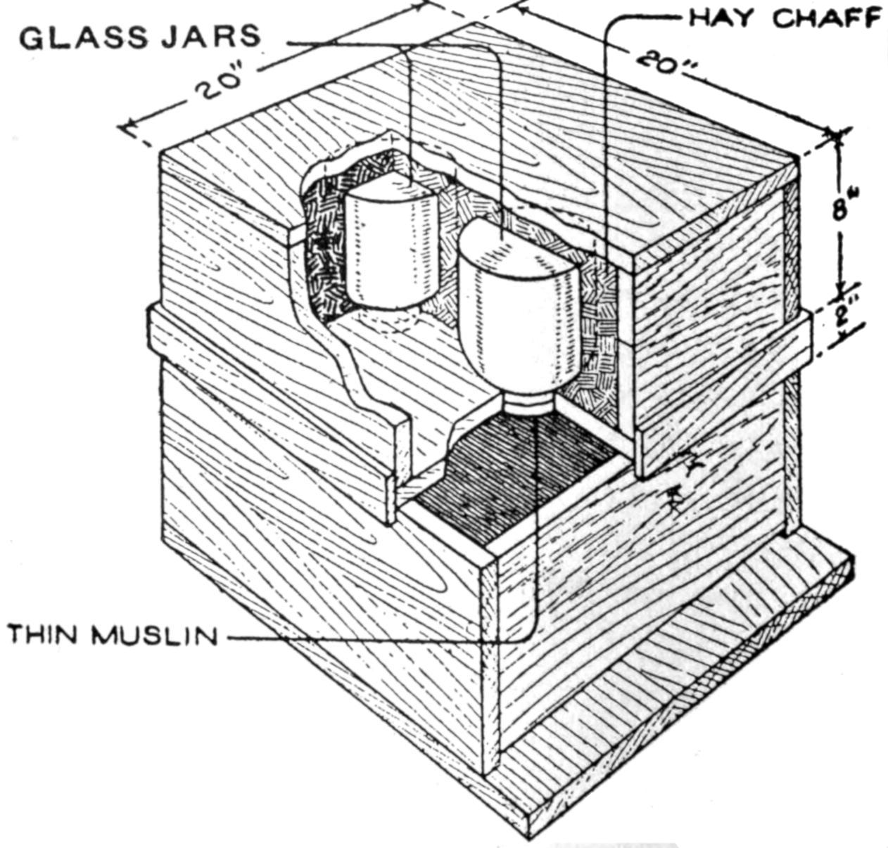
Sirup is Fed to the Bees in Winter and Protected from the Cold by the Feeding Jars Inclosed in the Box
The device is made as follows: Use wood smoothed on both sides; pine basswood, or other soft wood being satisfactory. Make two pieces, ⁷⁄₈ in. thick, and the same size as the top of the hive. Into one of these cut two round holes, as shown, to fit the necks of the jars. Make two pieces, 6³⁄₄ in. wide, for the sides, and two for the ends, the length being suited to the hive, the dimensions given in the sketch being suggestive only. Make four strips, 2 in. wide, and long enough to fit the four sides of the box. Nail the pieces of the box together, as shown, nailing the sides over the end pieces, and the top over the frame of sides and ends. Pack chaff into the box, and, after filling the jars with sirup and covering their openings with[193] muslin, pack the jars into the box so that their openings will be level with the bottom through which the holes have been cut. Fasten the board, with holes for the jars, into place with screws, so that it may be removed when it is desired to remove the jars for refilling. Nail the 2-in. strips around the lower edge of the box so as to cover the joint between the box and the hive. The feeder is then fitted into place, the bees feeding from the surface of the muslin. The chaff prevents the sirup from congealing in cold weather and so it is always available for the bees. The use of this simple device will prove economical and practical in keeping bees over the winter, assuring them a good food supply, with little effort on the part of the keeper.—Gus Hansen, Peachland, B. C., Can.
Nails, or spikes, may be driven into hard wood without causing them to buckle by applying a coating of vaseline, beeswax, and rosin, mixed in equal portions. A convenient method of applying the mixture is to bore a hole in the end of the hammer handle and fill it with the material. The nails may be pressed into the hole to coat them.—O. Root, Lorain, Ohio.
The porch is a convenient play spot for the children, but must be properly safeguarded to prevent not uncommon accidents and injury by falls. The folding gate shown in the sketch provides substantial barrier to the head of the stairs, and may be quickly folded out of the way. It is hardly noticeable when set in the side of the pillar, and does not mar the finish or general effect of the latter.
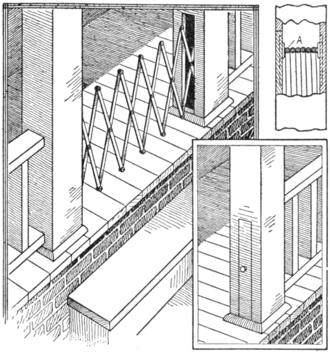
The Gate is Folded When Not in Use and is Concealed in the Hollow Porch Pillar
The gate is made of strips of band iron, although wood may be used. The strips are fastened with bolts, or rivets, and the forward end is fitted to the section of the pillar, which forms the cover for the recess in which the gate is housed. The cover is hooked to the opposite pillar when the gate is opened. Any suitable height may be chosen for the gate, but, for the purpose suggested, 24 to 30 in. is satisfactory. The device may be adapted to a variety of other uses by providing a box or chamber for the collapsed gate, when no hollow recess is otherwise available.
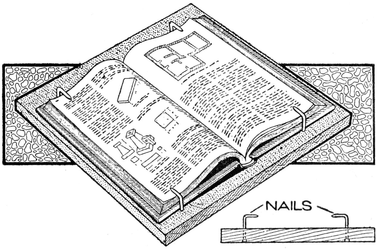
Nails Driven in a Board and Bent in the Shape of Screw Hooks to Hold a Book
A piece of board and four finishing nails furnished me with the necessary materials to construct a book-holding apparatus when in a hurry. Each nail, being driven through the board, could be turned to release, and pulled out far enough to accommodate a thicker book. In fact the device was adjustable.
[194]
A mystifying card trick, in which the performer makes use of the enchanted card frame shown in detail in the illustration, is as follows: A pack of playing cards is given to one of the spectators, who selects a card, noting the number and suit. The card is then placed in an envelope and burned by the spectator. The performer takes the ashes and loads them into a pistol, which he aims at a small frame, shown as empty, and set upon a table a few feet distant. The frame is covered with a handkerchief, and the pistol is fired at the frame. On removing the handkerchief the selected and destroyed card appears in the frame, from which it is taken at the back.
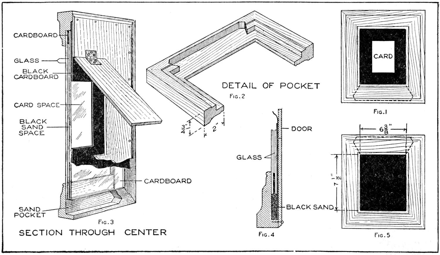
| Fig. 3 | Fig. 2 | Fig. 1 |
| Fig. 4 | Fig. 5 |
A Pocket is Cut into the Frame, and Filled with Black Sand, Obscuring the Card When the Frame is Inverted
The trick is performed as follows: A forced deck is prepared having 24 like cards, and the backs of the cards are held to the spectators when a card is selected. The frame is made of a molding 2 in. wide, mitered at the corners, and of the size indicated, the opening being 6³⁄₈ by 7¹⁄₂ in. The general views of the frame in normal position and inverted are shown in Figs. 1 and 5. A pocket is cut in the lower edge of the frame at the back, as shown in detail in Fig. 2. A pane of glass is fitted into the frame, and on the three edges other than the one having a pocket, strips of cardboard, ¹⁄₈ in. thick, are glued, as a bearing for a second piece of glass, as shown in Fig. 4. The back of the frame is fitted with a cover of thin wood, and a hinged door is arranged in the center of the back, as shown in Fig. 3.
A mat of black cardboard is fitted into the frame to form a background behind the card, Fig. 1. The pocket at the bottom is filled with black sand—that used by sign painters is satisfactory—and the frame is ready to receive the card for the performance of the trick. One of the cards from the forced deck is placed in the frame. By inverting the latter the sand is caused to run between the glass partitions, concealing the card on the black mat behind it. In this condition it is exhibited to the spectators and then placed upon the table. A handkerchief is thrown over it. The pistol is one of the toy variety and a cap is fired in it. In picking up the frame the performer turns it over, while removing the handkerchief, so that the black sand runs back into the pocket in the frame.—Harry Marcelle, Honolulu, H. I.
[195]

A child in the “toddler” stage should be provided with a safe place in which to play without disturbing the household routine of the busy mother too frequently. The folding wood-and-wire fence shown in the illustration meets this need in a practical and inexpensive manner. It may be used in the home or out of doors, the fence being especially useful in the latter case, since it protects the child, and likewise the lawn flowers, which a youngster, unguarded, may injure. The fence is 25 to 32 in. high, strong enough to support a grown person sitting on the edge of it, and incloses an area of about 4 by 6 ft. This is ample for the child, and the folded fence is thus not too bulky to be transported easily. The materials cost less than $3.50, including hardware for the making of the fence, as shown in the working drawings. The wood used for the main frames is ¹⁄₂ by 2 in., and they are covered with wire mesh, the edges of which are nailed under strips, on the outer side of the frames. Care should be taken to insure that none of the wire strands is exposed, thus endangering the child, or the clothes of passers-by. The frames are hinged together, as shown in the plan, and fold into compact form. Two long and four short frames are required. Cut the top and bottom rails of the long frames 6 ft. in length, and those of the shorter frames and the stiles 25 in. The corner joints are cross-lapped by cutting away one-half the thickness of each strip, as shown at A. The joints at the top and bottom of the center stile, or vertical piece, are made as shown at B, and the joints at the crossing of the center stiles and the cross braces, as at C. The braces only are notched to fit the stile. Each of the joints is fastened with flat-head screws, countersunk. The ends of the braces are cut to fit flush into the corners of the frames, and are nailed in place. This provides a flat nailing surface for the wire mesh and the strips that cover its edges.
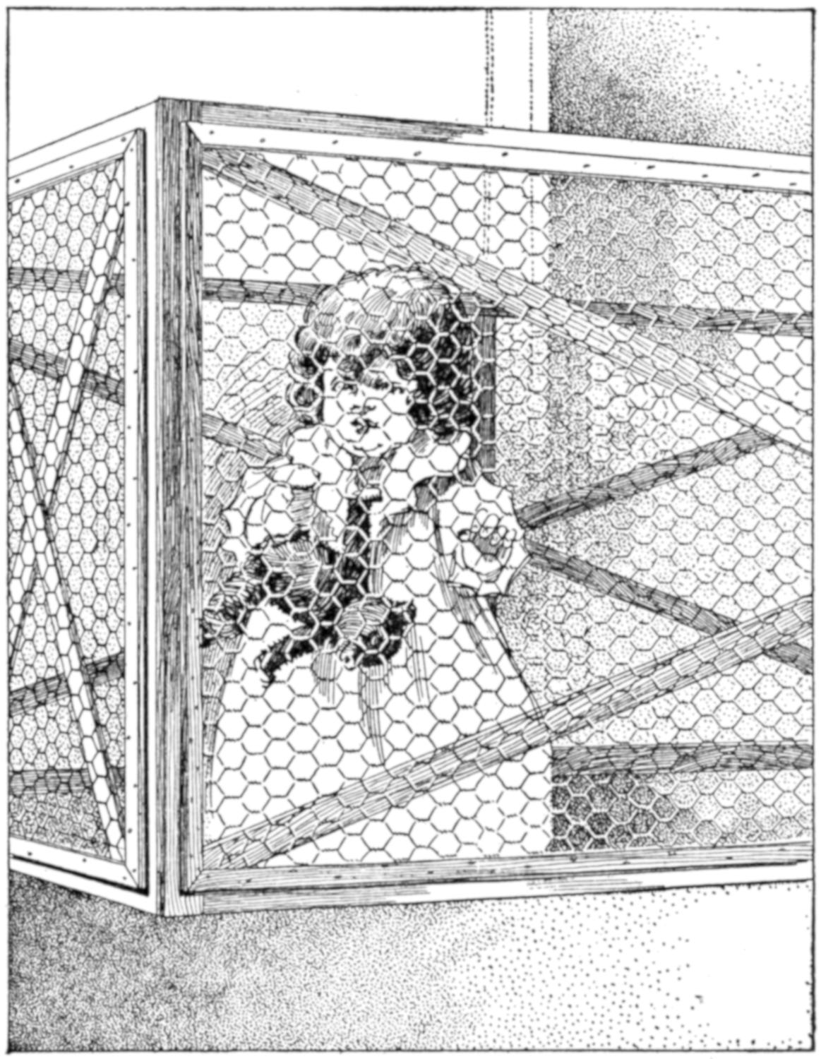
A Safe Play Space Either Indoors or Outdoors is Provided for the Child, and the Fence may be Moved Easily. The Construction Is Light yet Stable, and can be Carried Out without Difficulty by the Home Woodworker
Before putting on the wire mesh, all the exposed corners should be “broken” slightly with sandpaper, the wood wiped smooth, and finished with a coat of shellac. The wood may, of course, be left unfinished. In fixing the 1-in.[196] wire mesh in place, fasten one end of the piece squarely at the end of the frame, nailing it with staples. Place a strip of wood under each end of the frame and bear down on the middle of the frame, or weight it, to produce a bowed effect. Then nail the other end of the wire securely; on removing the strips, the wire will be drawn taut. Tack the edges down, and repeat this process on the other frames. Next nail the covering strips on the front faces of the frames, mitering them at the corners, as shown at A.
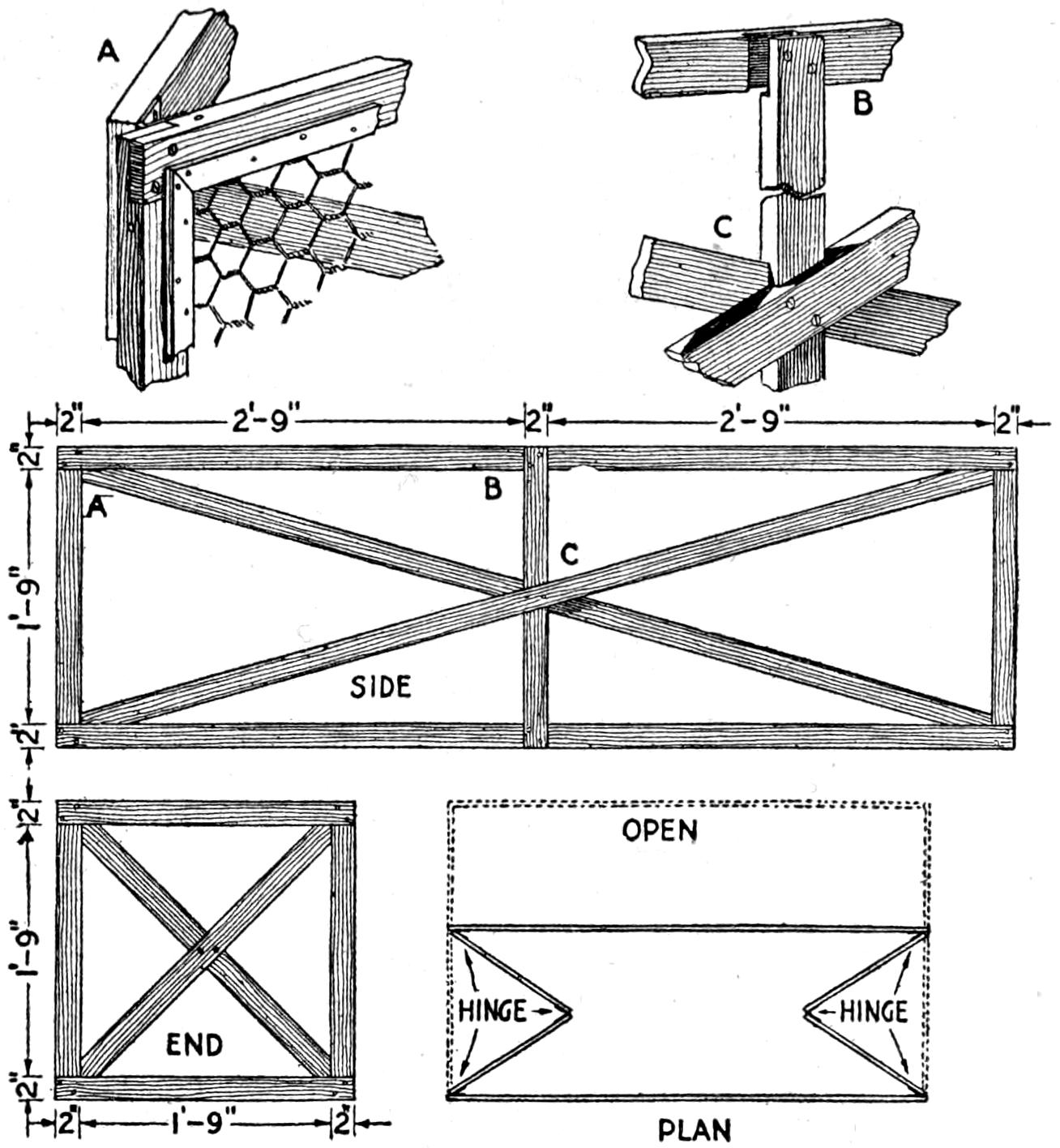
Join the Pieces with Well-Made Lap Joints, and Hinge the Frames as Indicated
The frames are then joined by means of hinges, as shown in the plan at A. Care should be taken that they are set so that the corners of the fence meet squarely and evenly when it is opened. Metal drawbolts should be fastened horizontally, one on the top of each folding joint between the end sections. These will prevent the child from folding the ends in, and possibly injuring its fingers. The completed fence is then given a final coat of shellac or varnish, the galvanized wire being left unfinished.
The materials required for the fence are as follows, the wood being listed in lineal feet, and smoothed on four sides to the dimensions indicated:
| 155 | ft. ¹⁄₂ by 2-in. clear pine |
| 50 | ft. ¹⁄₄ by 1-in. clear pine |
| 22 | lineal ft. 1-in. mesh, 2-ft. wide wire fencing. |
| 6 | pairs 1¹⁄₂ in. iron plain butt hinges, with screws. |
| 2 | steel drawbolts, with screws. |
| ¹⁄₂ | pt. white shellac. |
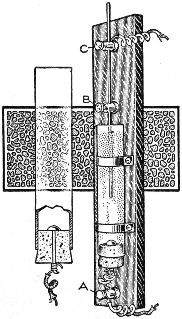
The rheostat shown in the illustration can be made quickly and at small expense. The base consists of a piece of wood, ¹⁄₂ by 2 by 12 in. A glass tube, 1 in. in diameter and 6 in. long, is fastened to this with strips of sheet metal. A large brass tack is driven into a cork, and the cork is inserted in the lower end of the tube. A wire runs from the brass tack to the binding post A. The lower part of the tube should be paraffined to make it water-tight. A brass or copper rod is placed through the binding posts B and C. The resistance can be changed by sliding the rod up or down. The tube is nearly filled with water having a small quantity of salt dissolved in it. The amount will depend upon the current to be reduced. The rheostat should be fastened to a wall, or other support, and may be used to regulate the speed of small motors and other electrical devices.—R. R. Wayt, Pittsburgh, Pa.
In the lecture and classrooms of a large university it was found that reflections of the electric-light bulbs in the glazed porcelain reflectors were extremely annoying to the eyes of students, and concentration of sight on the blackboard was difficult. A number[197] of tests were made, and the following method proved successful, eliminating the glare and the reflections. Large sheets of white blotting paper were cut to fit the inside of the reflectors, and then glued to their surface. The soft, somewhat rough surface of the blotting paper diffused the light, so that the glare was overcome.—C. M. Hall, St. Louis, Mo.
Boys, and other amateurs, sometimes have need of a vise when a commercial article or one of standard type cannot be had readily. The devices shown in the illustration will give good service and can be made of material easily obtained. The vise shown in Fig. 1 was made of old machine parts, consisting of a bolt and a wing nut. The bolt A was flattened at one end and bent at a right angle. A hole to fit it was bored through the top of the bench B, and the washer C and wing nut D were put in place. The piece to be gripped is clamped under the end A. This device should be fitted near the end and front edge of the bench.
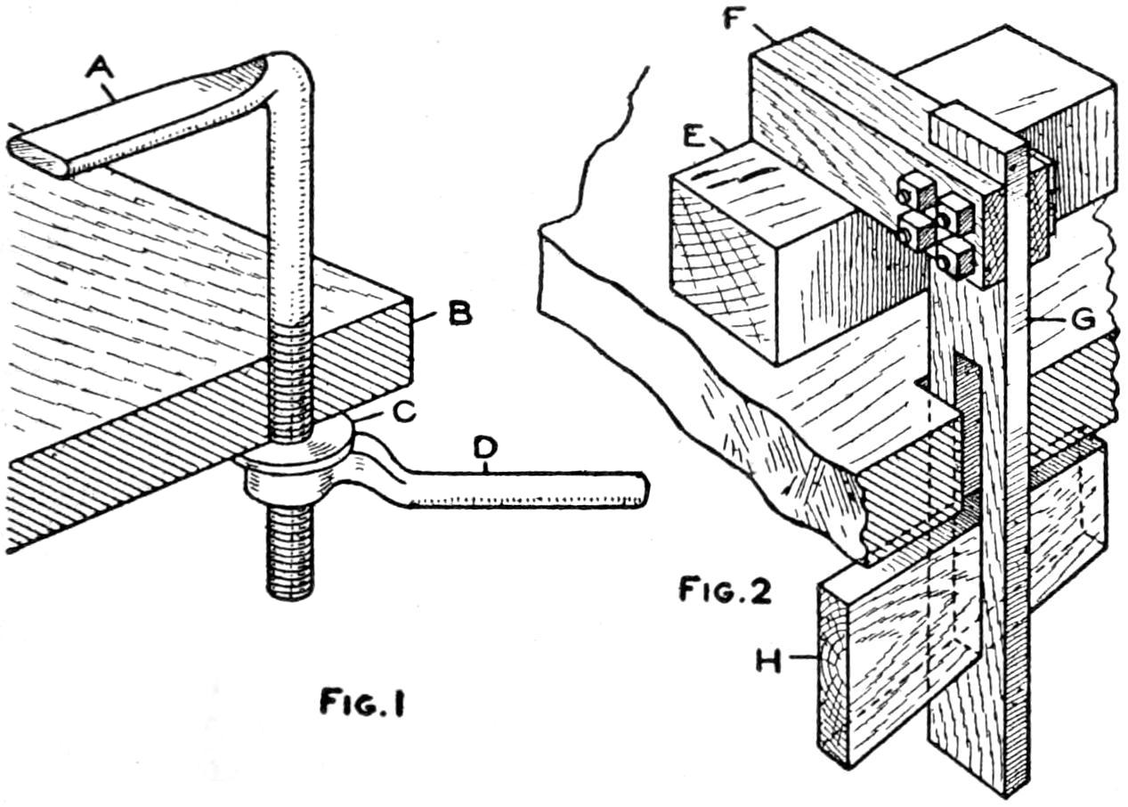
Fig. 1 Fig. 2
These Vises may be Made Easily of Materials Available in Most Workshops
The vise shown in Fig. 2 grips the block E in the same manner as the first vise. The jaw F is bolted to a vertical piece, G, which is fitted into a mortise cut through the bench top. The wedge H passes through a mortise in the piece G and clamps against the lower side of the bench top.—James E. Noble, Toronto, Can.
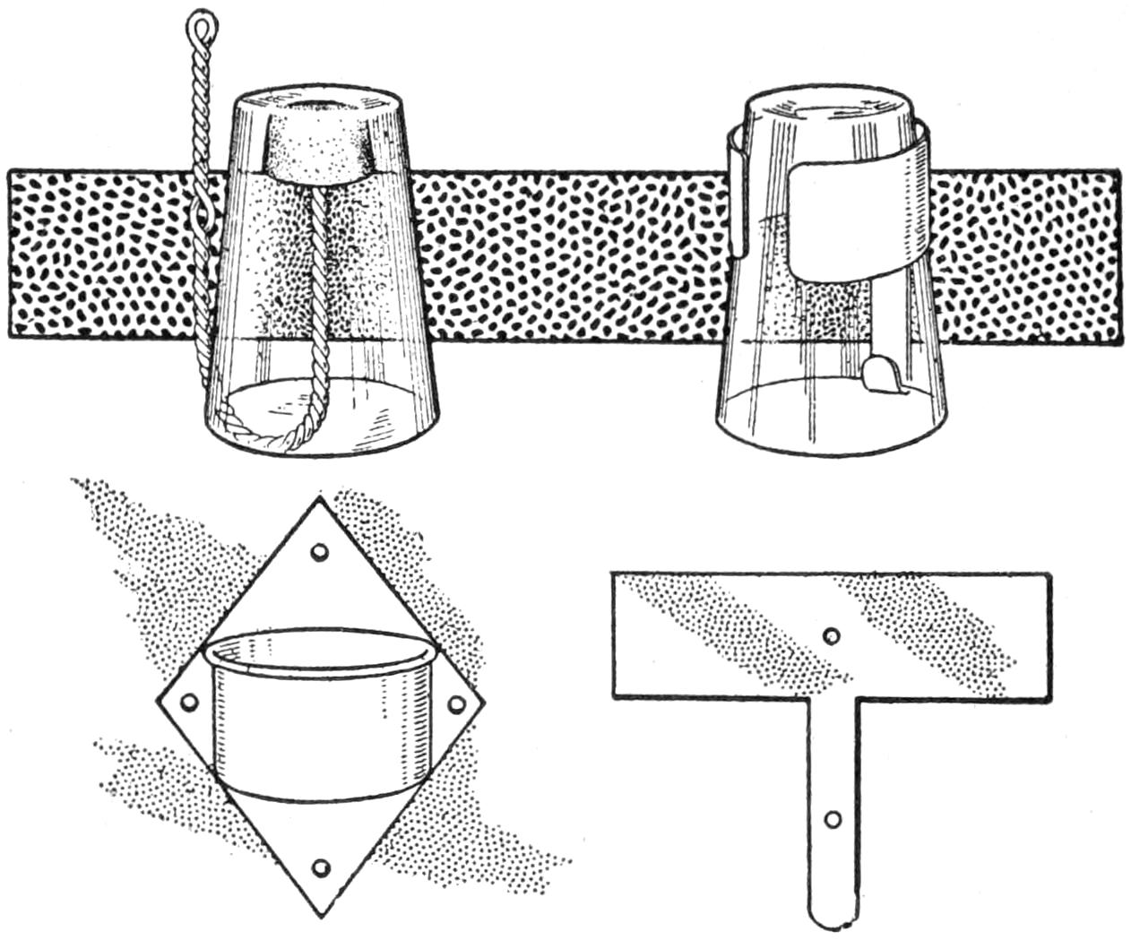
These Homemade Holders for Glasses Are Useful and Quickly Constructed
Several styles of holders for a drinking glass are suggested in the illustration. They may be made of durable materials easily obtained in the home workshop. The first is made by twisting a galvanized-iron or brass wire, as shown, with an eye and a loop for fastening it to the wall. A cork is fixed to the upper end, on which to rest the glass. The lower sketch shows a holder of the cup type made by riveting a metal cup to a diamond-shaped plate, the latter being fastened to the wall. The holder at the right is made from a piece of sheet metal cut to the shape indicated below. It is bent to the shape shown, and the lower end of the narrow strip is curved upward to provide a rest for the edge of the glass. The upper portion of the holder should be large enough so that the glass may be raised sufficiently to fit into the rest. The holes are provided for a fastening.—Frank L. Matter, Portland, Ore.
A convenient emery pad and needle cushion may be made by inclosing the powder in a long sack, about 1 in. in diameter, and sewing it in place around the arm of the machine. It will thus be close at hand and needles and pins may be stuck in the cushion, free from rust, and will not be in the way.
[198]

A Compensated Aerial Cableway
by Edward R. Smith
The possibilities for practical use as well as novelty for play and experimental purposes make the compensated aerial cableway, shown in the illustrations, not only interesting but also worthy of study. The arrangement assembled in its simplest form with two towers, in the page plate, shows how the weight of the car is compensated, so that a fairly level course on the track cable is provided. The various positions of the load and cables, showing the application of the compensating principle, are indicated in Figs. 1 to 5, and a multiple system is shown in Fig. 6. The details of the constructional parts are also shown. The car may be driven by wind power, as shown in Fig. 7, or by a motor, as in Fig. 8, in addition to the simple application of hand power suggested in the page plate. Devices for automatically reversing the course of the cars both for the sail rigging and with the use of electrical power, are shown in Figs. 7 and 8. By their use it is unnecessary to have an operator at each end of the cableway. The constructional features were worked out first by experiments on models in a shop, and then applied to a large rigging spanning over 100 ft. between the A-frames. The sketch in the page plate was made from photographs of this construction. Application of the compensating principle to carrying and transportation problems affords opportunity for interesting engineering, in spanning streams, cañons, or gulleys.
In most types of cableways a considerable sag is allowed in the cable supporting the car in addition to that caused by its own weight. Even in systems of practically constant cable tension, in which the wire is stretched by enormous weights, the loaded car causes a sag in the track cable, and ascends and descends an incline when approaching and leaving a tower. The aim in the compensated cableway is to overcome this sag as much as possible, and to offer a minimum of resistance to the car in its course.
The simple form of compensated cableway shown in the page plate is made by setting up two A-frames, with wire braces supporting them, and mounting the track and traction cables upon them. A light, flexible compensating cable extends from one tower to the other and is fitted to grooved pulley wheels at the tops of the towers, as shown in the detail at the right. The ends of the cable are fixed to wire hooks, from which the track cable is suspended. The latter is anchored at the ends of the wire braces supporting the A-frames. In order to understand the operation of the system it is desirable that the course of a load be traced in its various stages, as indicated in the diagrams, Figs. 1 to 5. For diagrammatic purposes the load is shown passing from the west slope to the east. As the load passes under the first A-frame, as in Fig. 2, the track cable is drawn down at that point; the corresponding end of the compensating cable is also drawn down, raising the opposite end of the track cable, and taking out most of the sag in the center portion of the track cable. As the load passes to the center position, as shown in Fig. 3, the track cable resumes a more nearly horizontal position. When the second A-frame is reached the load draws the corresponding end of the compensating cable down with the track cable, Fig. 4, and the latter assumes its normal position as the load reaches the end of the course. It is evident from the diagrams that the course of the load is more nearly level than it would be if the sagging of the track cable were not counteracted.
For use with a multiple-frame system, the cables are arranged in units between supports, as shown in Fig. 6. The compensating action is similar, the tendency being to level the entire course of the load. The weight of the car and load only is compensated, and since the weight of the cable will cause a sag, the course cannot be level, but may approach this condition.
[199]
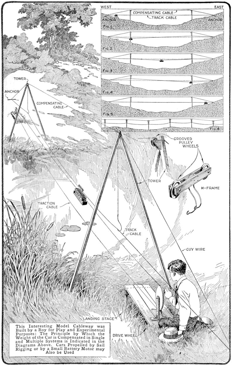
Fig. 1
Fig. 2
Fig. 3
Fig. 4
Fig. 5
Fig. 6
This Interesting Model Cableway was Built by a Boy for Play and Experimental Purposes: The Principle by Which the Weight of the Car is Compensated in Single and Multiple Systems is Indicated in the Diagrams Above. Cars Propelled by Sail Rigging or by a Small Battery Motor may Also be Used
[200]
A model of the compensated cableway, as shown in the page plate, or on a smaller scale, may be made by a boy of fair mechanical skill. For experimental purposes the detail may, of course, be refined to a high grade of workmanship, if desired. The size and dimensions of the parts need not be proportioned precisely as shown, but may depend more or less upon the materials available. The track cable should be made of galvanized-iron wire, the compensating cable of fishline, and the towers of 1-in. stuff, the width of the pieces making up the A-frames being increased in proportion to the height. Grooved pulley wheels, set in housings fixed to the top of the A-frames, carry the compensating cable. These may be made of wood, built up in three sections, to provide a flange on each side of the cable groove. The A-frames should be joined strongly at the top, and braced to anchors, sunk into the ground as shown. The hooks from which the track cable is suspended are made of heavy wire, bent so as not to interfere with the H-frame hanger supporting the car, and looped around the cable.
Various types of hangers may be devised to house the two pulley wheels which ride on the track cable. A simple H-frame hanger is shown in the detail sketch in the page plate. The grooved pulley wheels are set on bolts, and a heavy wire is bent and set through the center block as a support for the car. For experimental purposes, or even for play, when it is not desired to make a more elaborate car, a wooden block or other object of sufficient weight may be used as a load. An interesting feature of the work, especially for a boy, is to devise a realistic coach model, as suggested in the sketch. A wooden block forms the base, and the roof and platforms are made of sheet metal. The windows and doors are painted on the metal. The inventive boy may, of course, build a car with a hollow metal or wooden body, and weight it properly to provide the necessary load.
The motive power is provided by means of a cord, or traction cable, carried around two large grooved pulleys, mounted in supports fixed to the landing stages at each end of the cableway. They are made of wood, a suitable groove being cut around the edge with a saw, and smoothed with a small round file, or sandpaper wrapped over a round rod. The traction pulley is turned by means of a crank, set on the bolt which is used as an axle. The traction cable must be drawn sufficiently taut to provide the necessary pressure on the grooved pulleys, or it will slip. Rosin applied to the pulleys and the cable will tend to prevent this.
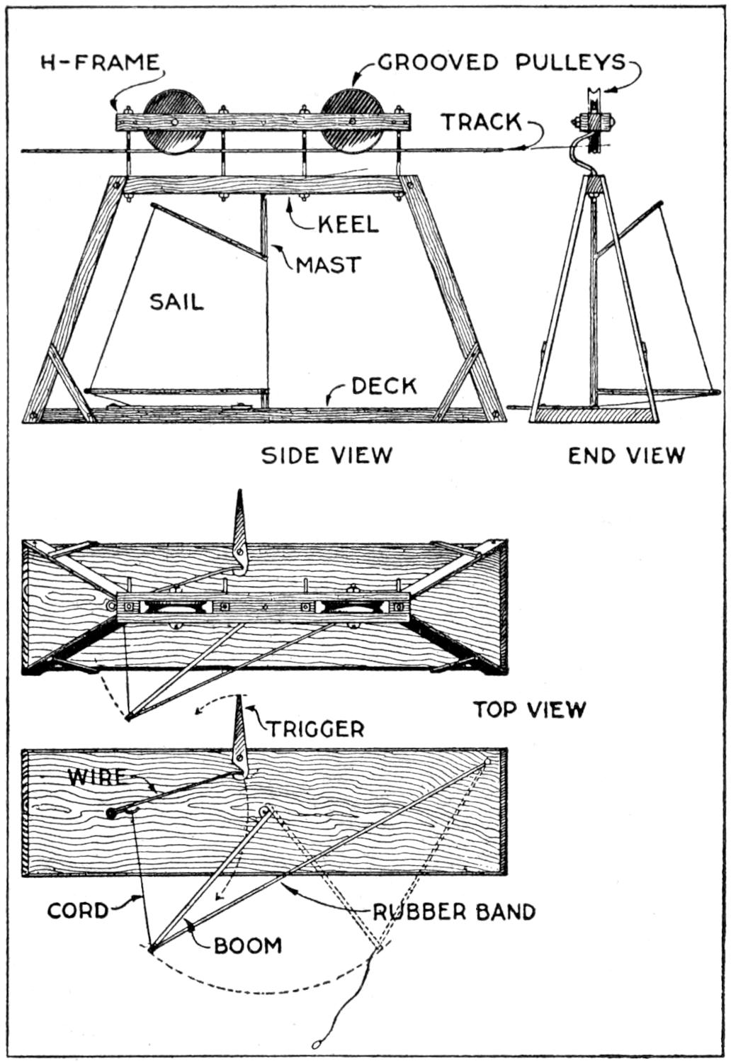
Fig. 7
The Car is Propelled by the Wind Action on a Sail Controlled Like the Main Sheet of a Sailboat in Tacking. The Trigger Device Releases the Sail, Reversing the Course of the Car
If the frames and other fittings have been properly set up, the cableway will support a sail car, shown in Fig. 7, or a two-cell electric car, driven by a small motor, as shown in Fig. 8. The sailing-car arrangement is often feasible,[201] since a stiff breeze is common in gorges, cañons, narrow valleys, or even in ravines where such a cableway might be set up. The hanger is an H-frame having the grooved pulleys bolted in it, and further reinforced by small blocks at the ends. A braced frame, supporting a deck on which a mast is set, is suspended from the hanger by four curved wires, as shown in the side view, Fig. 7. A sail with boom and gaff is supported by the mast. It is arranged to be shifted around the mast, which is accomplished automatically at the end of a run, or “tack,” by means of the trigger device shown in the top view. The sail is controlled in relation to the wind much as is the main sheet of a sailboat. The car can be operated in this manner only at right angles to the direction of the wind, or nearly so. For play purposes, a boy stationed at each end of the cableway can shift the sail, but the trigger device shown makes this unnecessary. A rubber band is attached to the boom, as indicated in the top view, and a cord and wire are arranged to engage a trigger. A stop for the trigger is fixed to the A-frame so that it is sprung when the car reaches the end of the run. The rubber band reverses the sail, the car having been set on the cable originally so that the forward end is in proper relation to the wind.
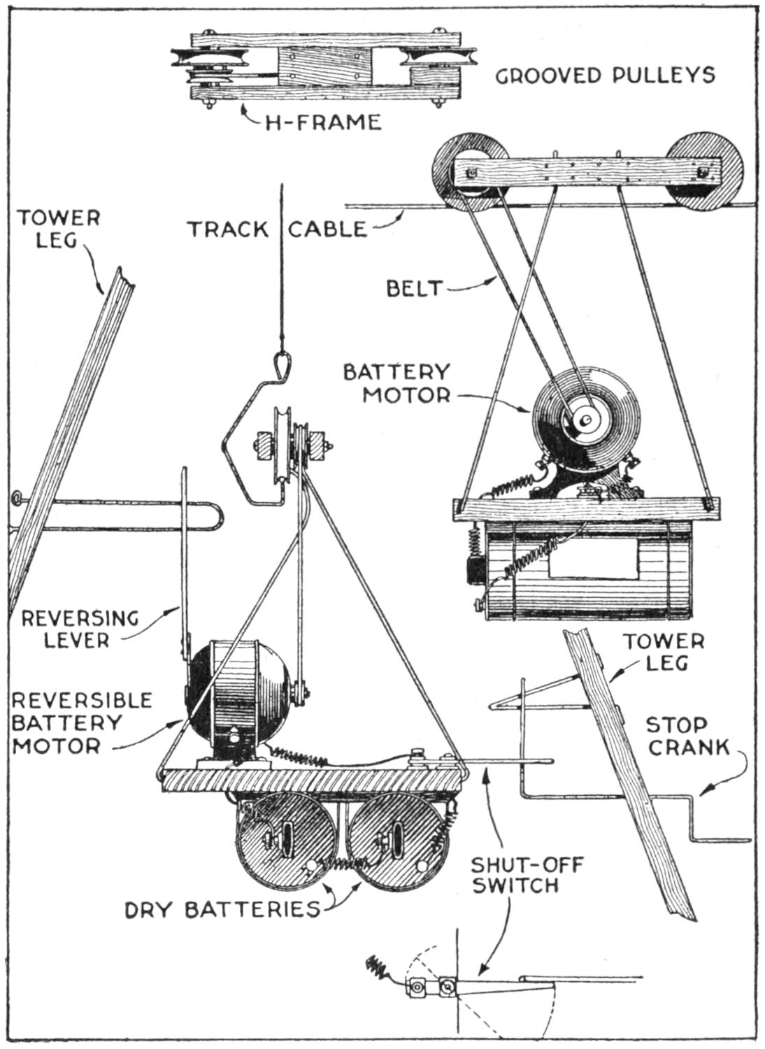
Fig. 8
The Electric Car Is Self-Contained and may be Reversed Automatically, if the Motor Is of the Reversible Type, by Contact of the Lever with the Stop Fixed to the A-Frame
The electric car is especially interesting in that it provides self-contained motive power by means of a battery of dry cells, and a motor belted to the hanger, as shown in Fig. 8. The hanger is of the H-frame type with heavy blocks between the sidepieces to provide for the small grooved driving pulley set on the axle of one of the larger pulleys. A wooden deck, supported by four heavy wires set into the center block of the hanger, carries the motor, and the dry cells are fixed under it. The motor is of the small reversible battery type, and should be provided with a reversing lever. This will make it possible to reverse the car when it reaches the end of its course. The motor and cells should be disposed so as to balance, tests being made for this purpose before setting them in place finally. A cord or small leather belt connects the drive pulley of the motor with the proper pulley on the hanger. These pulleys should be in line, and that on the hanger should be five times the diameter of the one on the motor shaft. The power is shut off at the end of the course by a shut-off switch which strikes a stop crank attached to the A-frame. When the reversing lever and stop are used, the stop crank is unnecessary. A nonreversing motor can be made to drive the car in a reverse direction by removing the belt from the motor pulley and replacing it to make a figure-eight twist.
¶When babbitt metal is heated some of the tin and antimony in it is burned out, making it unsuited for use in machinery bearings, and similar purposes, after several heatings. The oxidation of the metal is indicated by the formation of a scum on the surface.
[202]
A Miniature Fighting
Tank
That Hurdles Trenches
By EDWARD R. SMITH
Among the engines of war in action on land, probably none has created greater interest than the now famous “fighting tank,” which, according to reports, pours out missiles of destruction on the enemy from armored turrets, and crawls over trenches, shell craters, and similar obstructions, like a fabled giant creature of prehistoric ages. The tank described in this article, while not as deadly as those on the battle fields of Europe, performs remarkable feats of hurdling trenches, and crawling over obstructions, large in proportion to its size. The model, as shown in the heading sketches, is full-armored, and has a striking resemblance to these war monsters. The turret is mounted with a magazine gun, which fires 20 projectiles automatically, as the tank makes its way over the rough ground. The motive power for the tractor bands is furnished by linked rubber bands, stretched by a winding drum and ratchet device, on the rear axle, as shown in Fig. 1. When the ratchet is released, the rear axle drives the fluted wheels on it, and they in turn drive the tractor bands, as shown in the side elevation, Fig. 6. The wire-wrapped flywheel conserves the initial power of the rubber-band motor, and makes its action more nearly uniform.
The tank will run upward of 10 ft. on the rubber-motor power, depending on the size and number of the bands used. The gun is fired by a spring hammer, actuated by a rubber band. The trigger device is shown in Fig. 1. The pulley A is belted, with cord, to the front axle. Four pins on its inner side successively engage the wire trigger, drawing it out of the gun breech B, and permitting another shell to drop into place. As the pulley revolves, the trigger is released, firing the projectile. This process goes on until the motor runs down, or the supply of shells is exhausted.
The tank is guided by the pilot wheel, shown in Fig. 1. The sheet-metal armor, with its turret, is fitted over the mechanism, and can be removed quickly. It bears on angles bent up, as detailed in Fig. 2, to fit on the ends of the wooden center crosspiece of the main frame, and is held by removable pins at the ends of this frame. While the rubber motor is easy to make and install, the range of the tank can be increased by using a strong spring motor, the construction otherwise being similar.
The construction is best begun by making the wooden frame which supports the armor. The perspective sketch, Fig. 1, used in connection with the working and detailed drawings, will aid in making the latter clear. Make the frame C, as detailed in Figs. 5 and 6, ³⁄₈ by 1³⁄₄ by 11 in. long, with an opening cut in the center, 1 in. wide, 1 in. from the rear, and 1¹⁄₄ in. from the front end. Make the crosspiece D ³⁄₈ by 1³⁄₄ by 5⁷⁄₈ in. long; the gun support E, as detailed in Fig. 4, ³⁄₈ by 1⁵⁄₁₆ by 6¹⁄₄ in. long. Shape the support E as shown. Fasten the frame C and the crosspiece D with screws, setting the piece D 5³⁄₄ in. from the front, and its left end 3 in. from the side of the frame, as shown in Fig. 5. This is important, as the fitting of the[203] other parts depends on the position of these wooden supports.
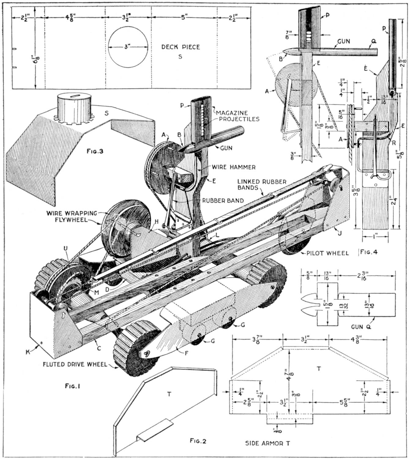
| Fig. 3 | Fig. 4 |
| Fig. 1 | |
| Fig. 2 | |
Perspective Sketch, Showing the Arrangement of the Parts, with the Armor and the Tractor Bands Removed, and Details of the Gun Mechanism and the Armor
The drive-wheel axles are carried in sheet-metal hangers, F, shown in Figs. 1 and 5, and detailed in Fig. 6. These hangers also carry bearing wheels, G, Fig. 1, which are held between the hanger F and a metal angle, as detailed at G, Fig. 6. These wheels are cut on a broomstick, and mounted on nail axles. The metal for the hangers F is drilled as shown, and bent double at the ends to make a strong bearing for the drive-wheel axles. The upper portion is bent at a right angle and fits over the top surface at the end of the crosspiece D, and is fastened to it with small screws or nails. Cut the stock for the hangers 2 by 6³⁄₈ in. long.
Next make the sheet-metal support H, Fig. 1, for the flywheel, the rim of which is wrapped with wire to give it added weight. Cut the stock, as detailed in Fig. 6, 1³⁄₄ by 4³⁄₁₆ in. long, and notch it to form the spring arrangement, which holds the flywheel so that the belt will be tight. The other sheet-metal support may then be[204] made also. Cut the stock for the front support J, for the rubber motor, 4¹⁄₈ by 3³⁄₄ in. long, and shape it as shown in the detail, Fig. 6. Make the support K from a piece of sheet metal, in general shape similar to that used for support H, the dimensions being made as required, and no spring arrangement being provided. Drill these metal fittings, as indicated, for the points of fastening, and mark the places for the holes in which shafts or axles run very carefully.
The driving mechanism can then be made, as shown in Fig. 1, and detailed in Figs. 5 and 6. The driving shafts and their parts, as well as the pulleys, can be turned in a lathe, or made from spools, round rods, etc. Make the front axle L, and wheels, joined solidly, 5³⁄₄ in. over all, the grooved wheels being ³⁄₄ in. thick, and 1⁷⁄₁₆ in. in diameter. Wires are used as bearings for shafts for the driving axles. If the rear axle is turned in a lathe, it is cut down to the shape indicated, thinner at the middle, to provide a place for the cord connected to the rubber motor. The grooved pulley and the fluted drive wheel at the winding-key end, shown in Fig. 5, are then cut loose; the drive wheel on the other end is cut loose, forming three sections, mounted on the wire axle, one end of which is the winding key. Ratchet wheels, M, are fitted between the ends of the center section and the adjoining pieces, the ratchet wheels being nailed to the center section and soldered to the wire axle. Pawls, U, are fitted to the inside of the two end sections, as indicated in Fig. 1 and in Fig. 5. When the rubber motor is wound up on the drum, the tractor bands are gripped until it is desired to start the tank on its trip. Then the power is communicated from the drum, or center section of the axle, to the drive wheels by means of the ratchet wheels, acting on the pawls.
Mount the hangers F on the center crosspiece D, fitting the axles of the drive wheels into place. Make the weighted flywheel, and mount it on its shaft, as shown, lining it up with the pulley on the rear drive shaft. Fit the supports J and K into place, setting spools for the rubber-motor cord in place, on wire axles. Arrange the belt from the flywheel to the drive shaft, and connect the rubber bands for the rubber motor as shown. Fasten one end in the hook of support J, and pass the winding cord through the spools, and fix it to the drive shaft. The device can then be operated with the fluted drive wheels, bearing on strips of wood for tracks.
The tractor bands N are fitted over the drive wheels, as shown in Fig. 6. They are built up of canvas strips, on which wooden shoes are glued and sewed, as detailed in Fig. 5. The stitches which reinforce the gluing are taken in the order indicated by the numerals. The pilot wheel is 2 in. in diameter, and sharpened at its circumference. Make a metal shell, O, for it, as detailed in Fig. 6. Solder the shell to the double wire, which supports the wheel and gives it a spring tension to take obstructions nicely. The wire is fastened to the crosspiece D, as shown in Fig. 5.
The gun and its mechanism can be made handily before the support E is fixed into place at the front of the crosspiece D. Shape the magazine P from sheet metal, making it 2⁵⁄₈ in. high, as detailed in Fig. 4. Make the gun Q from a piece of sheet metal, as detailed, cutting the metal to the exact dimensions indicated. Mount the magazine and the gun, and arrange the wire hammer R, and the rubber band that holds it. Fit the pulley A into place on its axle, supported by a small block of wood. Belt it to the front drive-wheel axle, as shown in Fig. 5, after the gun support is fastened into place with screws. Make the projectiles of wood, as shown, and the fighting tank is ready to be tested before putting on the armor.
The armor is made of one deck piece, S, Fig. 3, into which the covered turret is set, and two side pieces T, as detailed in Fig. 2. Make one left and one right sidepiece, allowing for the flanges all around, to be bent over and used for riveting or soldering the[205] armor together. The bottom extension on the sidepieces is bent double to form an angle, on which the armor is supported, where it rests on the top of the hangers F. The turret is fitted to the deck by cutting notches along its lower edge, the resulting strips being alternately turned in and out along the point of joining, as shown in Fig. 3. When the armor is completed, it is fitted over the main frame, the gun projecting from the turret. Small pins hold the ends of the armor solid against the ends of the main frame C, so that the armor can be lifted off readily. The various parts of the fighting tank can be painted as desired, care being taken not to injure the points of bearing, on the axles and pulleys, which should be oiled. Silver bronze is a good finish for the exterior of the armor, which may be decorated with a coat of arms.
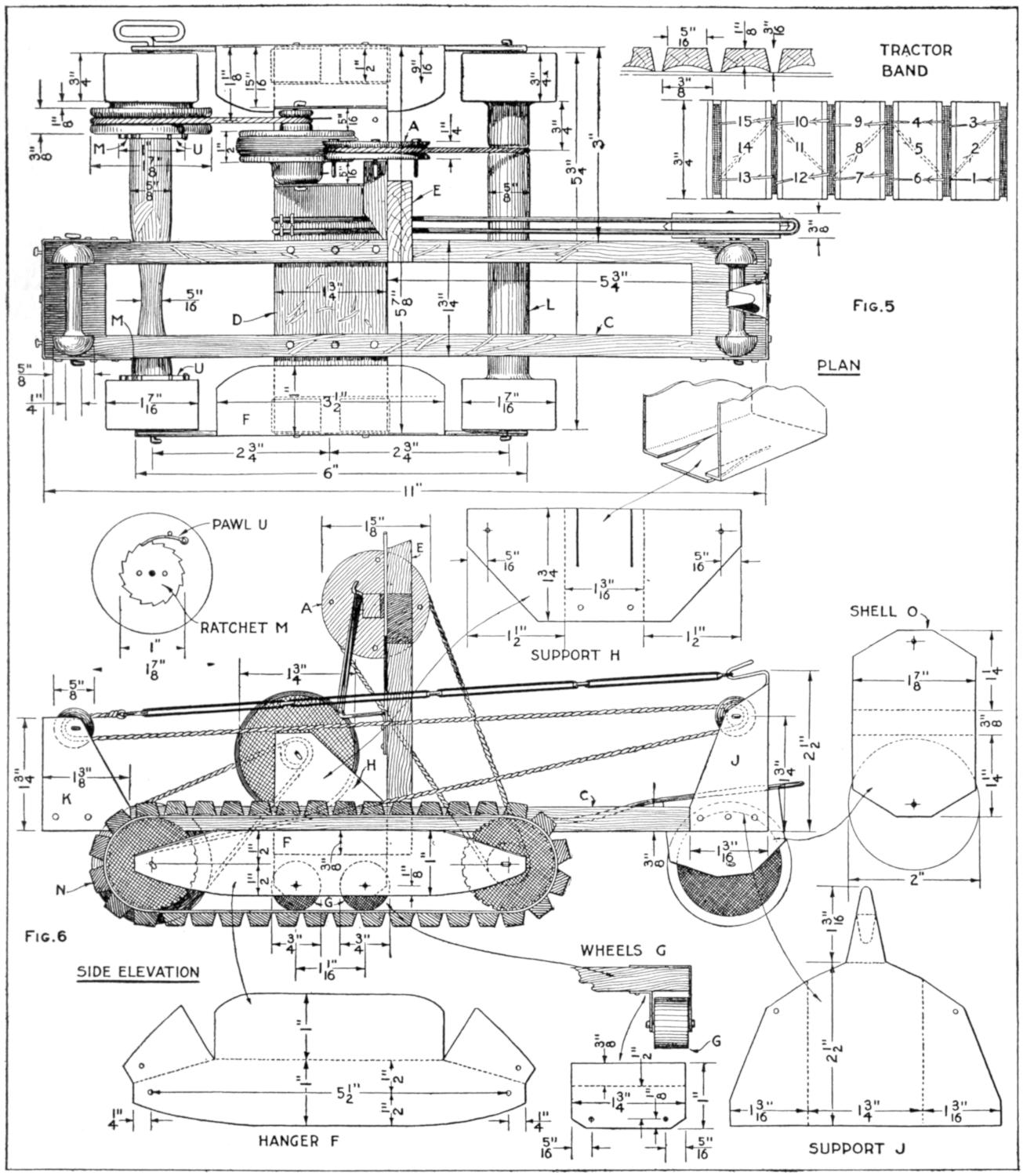
Fig. 5
Fig. 6
Plan and Side Elevation of the Interior Mechanism, with the Armor Removed, and Details of the Metal Fittings, the Ratchets, and the Tractor Bands
[206]
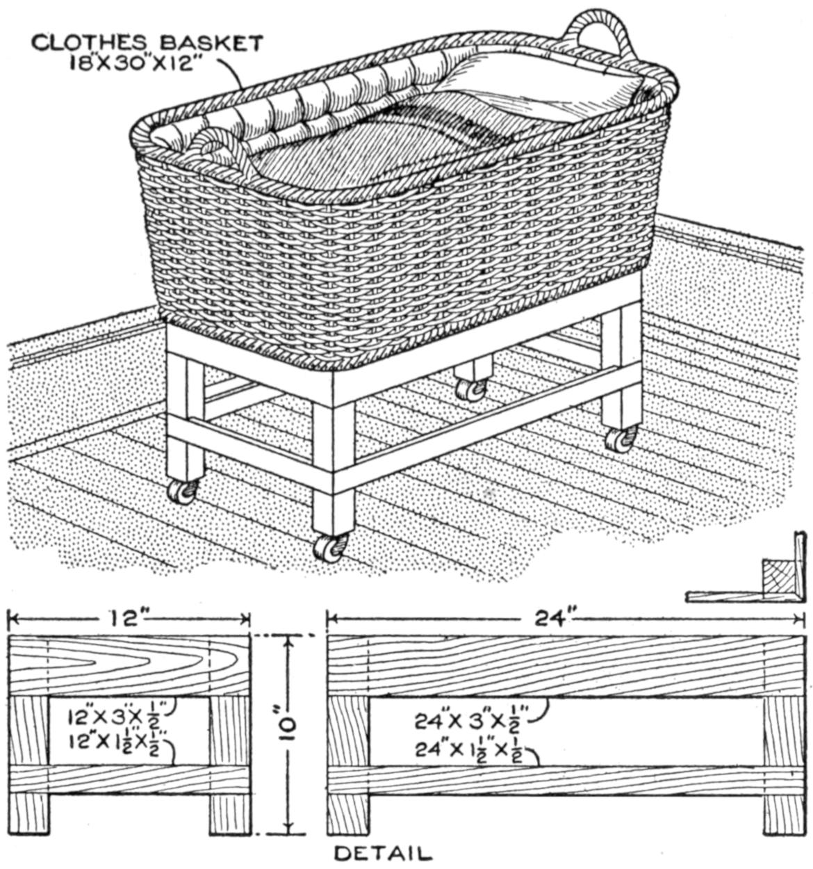
A Few Sticks of Wood and a Clothes Basket Make a Convenient Cradle for the Baby
A clothes basket on a simple but strong wooden frame, mounted on castors, makes a cradle which is as convenient and sanitary as many which are sold for five times its cost. It is light enough to roll out on the porch without difficulty, and may be padded and fitted with pillows until the most exacting mother is satisfied. The basket and frame should be painted, preferably some light color. The whole cost, not including pads or pillows, should not be over $2.50.—A. Switzer, Denver, Colo.
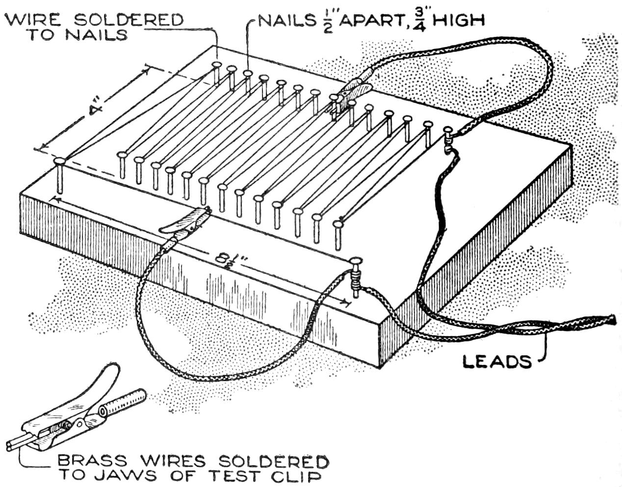
This Homemade Rheostat Has a Capacity of One-Half to Five Amperes, on a Six-Volt Circuit
A rheostat made as shown in the sketch has been used successfully for calibrating a large number of ammeters and wattmeters. One of the general designs suggested will be useful for many other purposes. The dimensions given were used for obtaining a variation of from ¹⁄₂ to 5 amperes with a 6-volt source of electromotive force. For other capacities the proportions may be increased or decreased proportionately. A piece of pine, 7 by 9¹⁄₂ in., forms the base. For resistance wire No. 16 gauge “Climax” was used, but wire of any material which will carry the maximum current without excessive oxidation may be employed instead. Nails support the resistance wire, which should be soldered to the nails to insure good electrical contact. Leads of flexible cord are arranged as shown. These are soldered to the first and last nails in the series. To provide connection between the free ends of the cord and the resistance wire or the nails, 5-ampere test clips are soldered to the cord ends. The teeth of the clip jaws are filed off, and in their stead a short piece of brass wire is soldered to each jaw, as indicated in the detailed view. A nick is filed in each of the brass wires so that they will hold firmly onto the resistance wire or nail. Suspender or display-case clips, suitably modified, may be substituted for the commercial test clips.
In using the device, one clip is moved along the front span. The other is gripped to a nail in the rear row. Sliding the front clip along the span wire insures a fine adjustment of resistance. Gripping the rear clip on the different nails provides the coarse adjustment—R. F. Binney, La Vina, Calif.
¶Glue applied to door-knob screws will prevent them from loosening easily, yet they may be removed without difficulty.
[207]
Typewriter paper may be fed from a roll where only one copy is necessary and where maximum speed of production is essential. Sections, not to exceed about 11 in. in length, of the typed paper are torn off as necessary. This practice is followed often in newspaper offices. The roll paper can be purchased at any paper-supply house, cut to the width required by the user. The construction of a roll-feed attachment which may be mounted on any of the standard typewriters will be described.
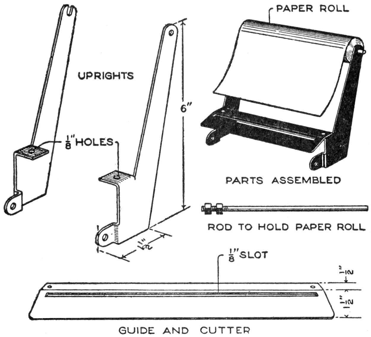
A Paper-Roll Holder for Typewriters That can be Attached to Any Standard Machine
First make the two uprights. Both are cut from ¹⁄₆-in. sheet brass, as shown. After cutting, heat the pieces to anneal them before bending. A hole is provided for the paper-roll rod in the right-hand upright and a slot in the left-hand one. A rod, threaded on one end and equipped with two nuts, constitutes the paper holder. For a guide plate and cutter, cut a piece of sheet brass, 1¹⁄₂ in. wide and of a length equal to that of the carriage, as detailed in the drawing. Bend it as shown. A ¹⁄₈-in. slot is cut almost the entire length of the guide.
In mounting the holder on the typewriter, the uprights are drilled at the base to engage the two small screws at the side of the carriage back of the roller. The exact location of these holes will vary in machines of the different makes. Next, the uprights are clamped into place with the screws, one at each end of the carriage. Then determine the distance between the arms of the uprights, drill a corresponding hole at each end of the guide-and-cutter plate, and fasten the plate to the uprights with small stove bolts. The roll of paper is placed on the rod and fed between the machine platen and roller as with single sheets. When the article or memorandum being written is finished, the paper is held against the guide plate and the blade of a pocketknife inserted in the slot. Passing the blade the length of the slot cuts off the paper, or it may be torn off at the slot. The end of the paper roll is again fed into the machine, ready for another operation.
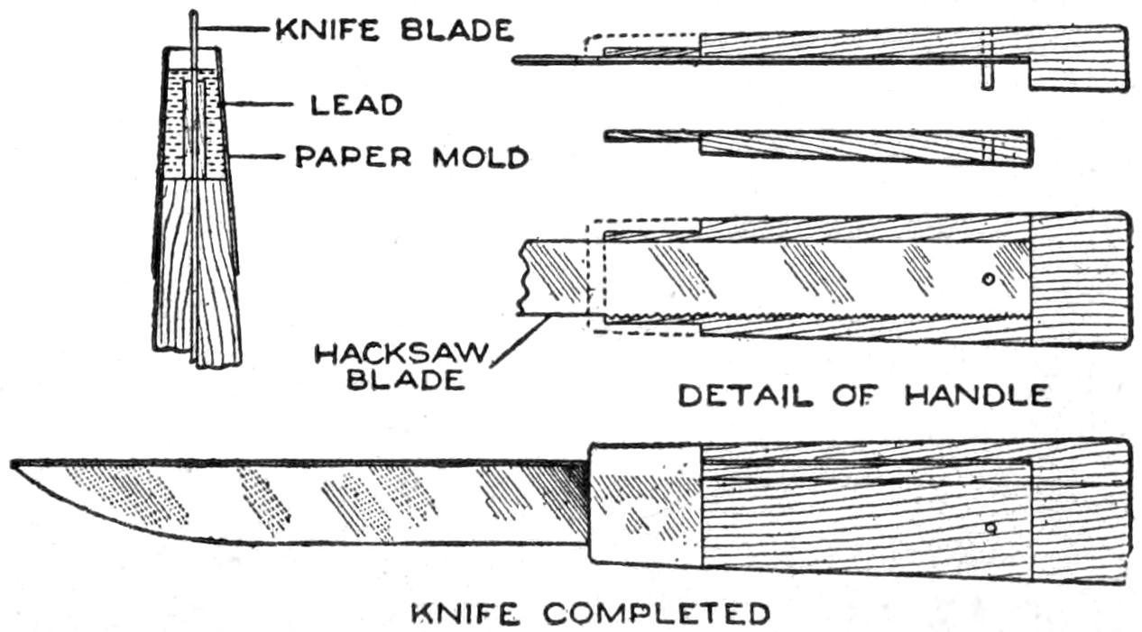
A Serviceable Paring Knife Made from a Piece of Hacksaw Blade, and Details of Its Construction: The Handle and Blade are Held Together with a Rivet and a Lead Ferrule
With a little work a hacksaw blade, or a portion of one, can be made into a paring knife that will prove very durable because of the excellent quality of the steel. Two pieces of hard wood should be cut into the shapes shown and riveted together with one end of the blade between them. After putting a paper mold about the end of the handle from which the steel projects, melted lead is poured into it, to form a collar that will hold the parts firmly together. The exposed part of the saw can then be ground as desired.
[208]
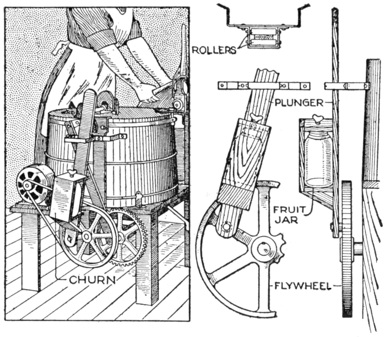
Without Impairing the Usefulness of this Washing Machine a Plunger has been Attached to the Flywheel Which Does the Work of a Churn, a Jar for the Cream being Installed as Shown
The owner of a power-driven family washing machine has provided an attachment for it with which he churns cream at a little additional expenditure of energy. A wooden plunger was bolted to the outside of the flywheel and its upper end placed between two rollers set in a metal frame attached to the side of the tub. Enough play was allowed between the rollers to permit the plunger to move up and down freely. A framework large enough to hold a glass fruit jar was attached to the side of the plunger, a thumbscrew being provided in its upper end with which the jar is held firmly in place. As the flywheel revolves, the movement of the plunger thoroughly agitates the contents of the jar.—Dale R. Van Horn, North Loup, Neb.
Apropos of the article in a recent issue of Popular Mechanics Magazine entitled “A Cedar-Lined Oak Chest,” readers who desire the advantages of a cedar-lined box or closet may accomplish it by the use of cedar oil. Painting the interior of a box with this oil will to all intents and purposes convert it into a cedar chest regardless of the kind of wood used. The cost of the oil is not great. A closet treated in the same manner will likewise keep out insects.—Robert E. M. Bain, St. Louis, Mo.
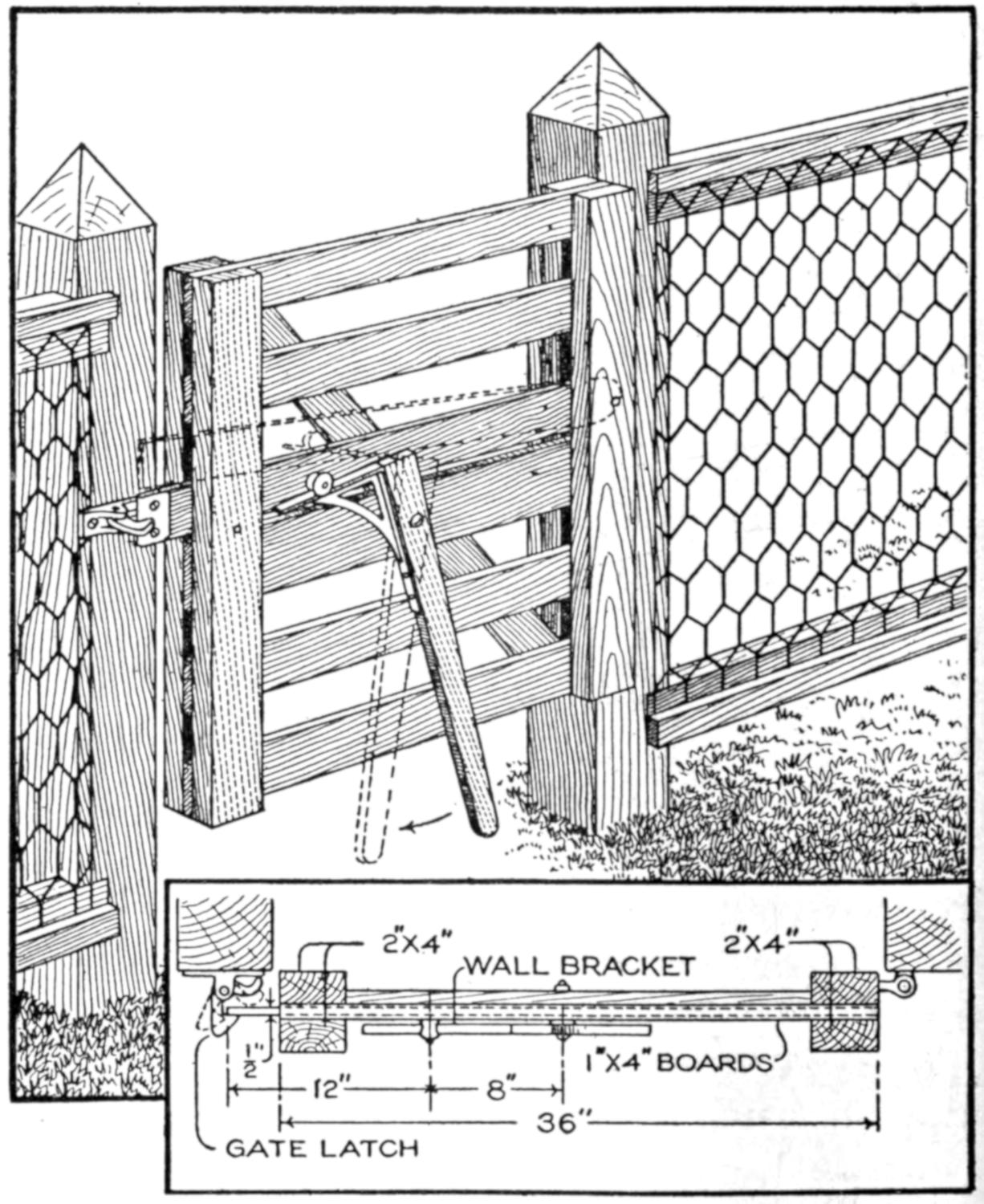
This Gate is Unlatched by Operating the Foot Lever as indicated. It Is a Special Convenience When One has Both Hands Occupied Carrying Pails or Bundles
A gate which can be unlatched with the foot has proven a great convenience across a path on a farm where laborers frequently pass with both hands occupied carrying pails. Pivoted to the side of the gate, near its center, a beam, or foot lever, is hung in a vertical position, extending almost to the ground and having a shelf bracket fastened to its upper end. The horizontal arm of the bracket passes beneath a porcelain knob projecting from a pivoted bar that engages the elbow catch. By pushing the vertical beam to one side with the foot the bar is raised above the catch, allowing the gate to swing open. If the gate is properly hung it will close of itself, the elbow catch serving to prevent its being opened again, except when the bar is raised.—T. C. McDowell, Adrian, Michigan.
[209]
An outfit which may be used for either projecting picture post cards or enlarging photographic negatives was assembled as delineated in the illustration. An ordinary camera, which provides the lens and bellows, is required, in combination with a dark box which can be built in the home workshop. The method of construction is this:
Make a box about 8 in. square out of ¹⁄₂-in. planed soft-wood stock. Nail the sides, but omit, for the present, the top and the bottom. The two openings thus left will be called the front and the back. Mount an 8 by 8 by ¹⁄₂-in. board, D, which constitutes a door, on the back with hinges and provide a hook to hold it shut. Cut a square hole, of the same size as that of the opening in the back of the camera which is to be used, in another 8 by 8-in. piece, E. This will constitute the front board. This front board is so cut that it fits in between the sides of the box instead of on the ends, as does the back. In the top, cut a square hole for ventilation. A hood is provided over this hole to prevent light being thrown forward.
When using the arrangement as a projector or magic lantern two 40-watt tungsten lamps, A, are required. Each lamp is mounted in a porcelain receptacle held on the floor with screws. A lamp cord, one end connecting the two lamps in multiple and the other fitted with an attachment plug, passes through a hole in the floor of the box. Form the two reflectors, B, of 8 by 7-in. bright tinned sheet-iron pieces, each having holes along one of its edges to admit of attachment. The reflectors are bent to a semicircular contour before mounting. The card holder is detailed at C. It is a piece of tinned sheet iron bent to the form shown so that it will hold a post card. A hole is drilled in its center for a screw pivot. It can then be fastened to the center of the back door and can be turned into position for either horizontal or vertical pictures. A washer is inserted on the screw between the holder and the door. The thickness of the camera body having been determined, a slide is fastened to the front board, as diagrammed, to support this body.
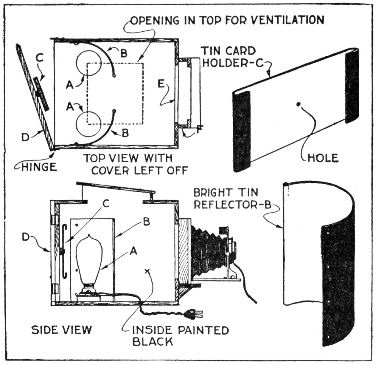
An Ordinary Small Camera, Fitted with This Attachment, Becomes an Enlarging and Post-Card Projecting Camera
Before it can be used as a projector it must be adjusted to operate with the camera of the type and size available. The adjustment, which must be made in a darkened room, having on one of its walls a white screen on which the image will be projected, is effected thus: Remove the back from the camera and place the camera in the slide without extending the bellows. Open the shutter. Insert a card in the holder C. Light the tungsten lamps. Now move the front board, with the camera carried on it, back and forth within the box until the components are in focus, that is, until the most distinct image obtainable is reproduced on the screen. Then, illuminate the previously darkened room and nail the front board in the position thus determined. These adjustments having been made, paint the box, inside and out, a coat of dead black. Everything should be painted black except the reflecting surfaces of the tin reflectors and the incandescent-lamp bulbs. The front board having been fastened, subsequent focusing can be effected by shifting longitudinally[210] the lens board of the camera. The image of any sort of a picture that will fit in the holder can be reproduced. Colored post cards will project in their natural tints.
To make enlargements with the same box, a few minor changes are necessary. When employed for enlargements the tungsten lamps, which are required for projection, are not used. They may, however, remain in the box and can be disconnected from circuit by unscrewing them a few turns. The negative, or film, which is to be enlarged, is held in the opening E. Where a film is to be reproduced, it is held between two pieces of glass which are fastened to the inside of the front board with small clips. If a glass negative is used, the two additional glass plates are unnecessary. If the negative does not fill the opening in the camera, a mask cut from heavy black paper will be required to cut off the light.
The light for the enlargement is furnished by another tungsten lamp mounted in a porcelain receptacle which is screwed to a board which constitutes a base. This light source is moved about in the house until it is directly back of the opening E in the front of the box and until the light is distributed equally over the entire negative. To focus, move the camera backward or forward. While focusing, use a yellow glass, or ray screen, to cover the lens. When focusing has been completed, the shutter is closed and the ray screen removed. Then stop down the lens to bring out detail, and expose.
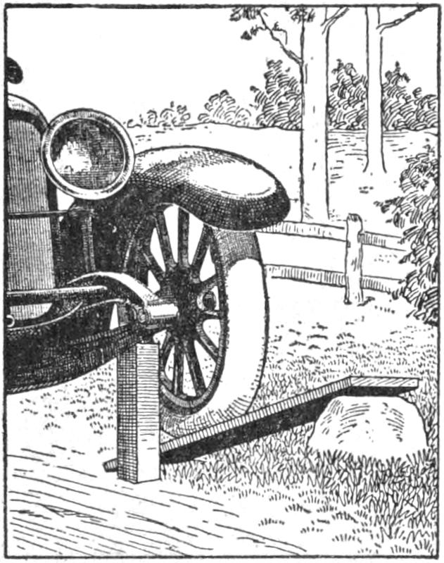
It occasionally happens that a motorist fails to have a jack at hand when a tire needs to be changed on the road. The situation is easily met with the aid of a strong board and a couple of blocks or rocks. Driving the desired wheel onto the incline, provided in the manner illustrated, and setting the brakes, a block is placed beneath the axle. The board is then knocked out of the way.—John Peters, Milwaukee, Wis.
A little padded platform on wheels takes most of the drudgery away from scrubbing in hotels and office buildings. The platform carries the pail as well as the scrubber, and enables the scrubber to keep dry.—Florence L. Clark, McGregor, Ia.
A couple eating breakfast and supper in their room used a chafing dish for cooking. A hard alcohol was used for fuel, and the expense seemed too high. So a fuel can was filled with pulverized asbestos pipe covering, and then saturated with wood alcohol. A quart of alcohol lasted about a month.—Charles A. King, Plymouth, N. H.
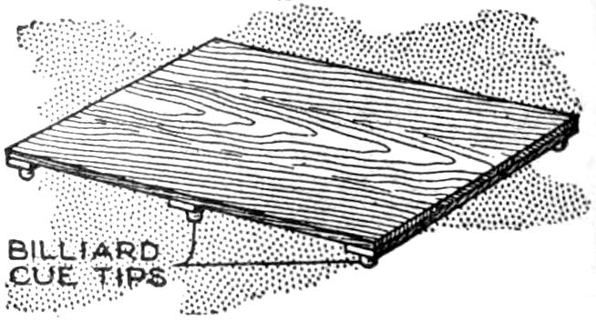
Attractive stands which will preserve the dining table from injuries, or heat marks made by hot dishes, can be easily made from thin pieces of board cut oblong or oval. After the board has been cut the proper size, cleats are fastened to the underside to which billiard-cue tips are attached to serve as supports. The stand should be varnished and waxed to match the table.—George L. Furse, St. Louis, Mo.
[211]
To make the curtain rings space automatically along the curtain pole, tie a cord from one ring to the next, spacing the rings uniformly. Or the cord may be attached at uniform distances to the curtain. A pull at the edge of the curtain will space the rings evenly every time.—Frank L. Matter, Portland, Ore.
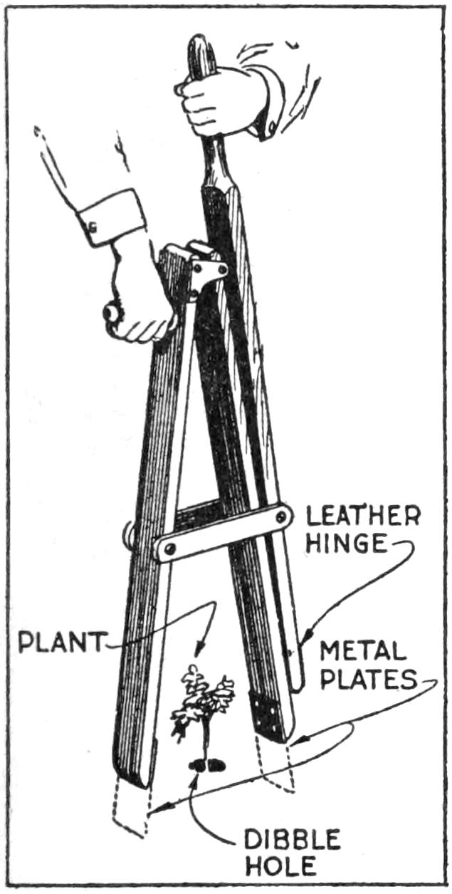
When tomato or cabbage plants are to be set out in considerable numbers, the simple implement shown here makes stooping over to press the dirt about the plants unnecessary. After a row of plants has been set in dibble holes and watered, the soil can be packed about their roots quickly while one is standing upright. The jaws of the device are actuated by means of the hinged lever.—A. S. Thomas, Amherstburg, Ont.
The following kink will relieve the housewife of the trouble of sagging clotheslines, and hubby of constantly being asked to tighten up the line. The cost should not be over 25 cents, as all that is needed is a pulley cleat and hook, all of which may be had at any ten-cent store. When the line gets slack, it is pulled tight through the pulley and tightened up in the cleat.—S. H. Johnson, Westville, Conn.
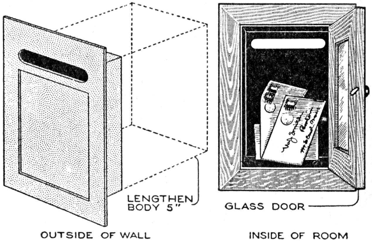
The Mail Box is Lengthened So That It Reaches through the Wall to the Inside, Where a Door is Placed through Which the Mail can be Removed
A person having a mail box set flush in the outside wall of his home can, with a little alteration, make it accessible from inside the house: After removing the back side of the box a tin extension should be soldered to the box giving it sufficient length to reach through the wall in which an opening of the proper size has been cut. The enlarged container is completed by adding a glass door to the inner end which enables one to ascertain its contents at a glance.—A. Pertle, Chicago, Ills.
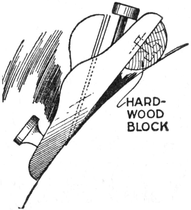
Few amateur craftsmen can afford to own a circular plane, yet this tool is decidedly necessary for such round work as table tops, half-round shelves, segments, and the like. Any ordinary block plane will accomplish such work if equipped as illustrated. A piece of half-round hard wood is cut the width of the plane and attached with countersunk machine screws, as indicated. The block elevates the rear end of the plane, causing it to follow the curve of the work on which it is used.
[212]
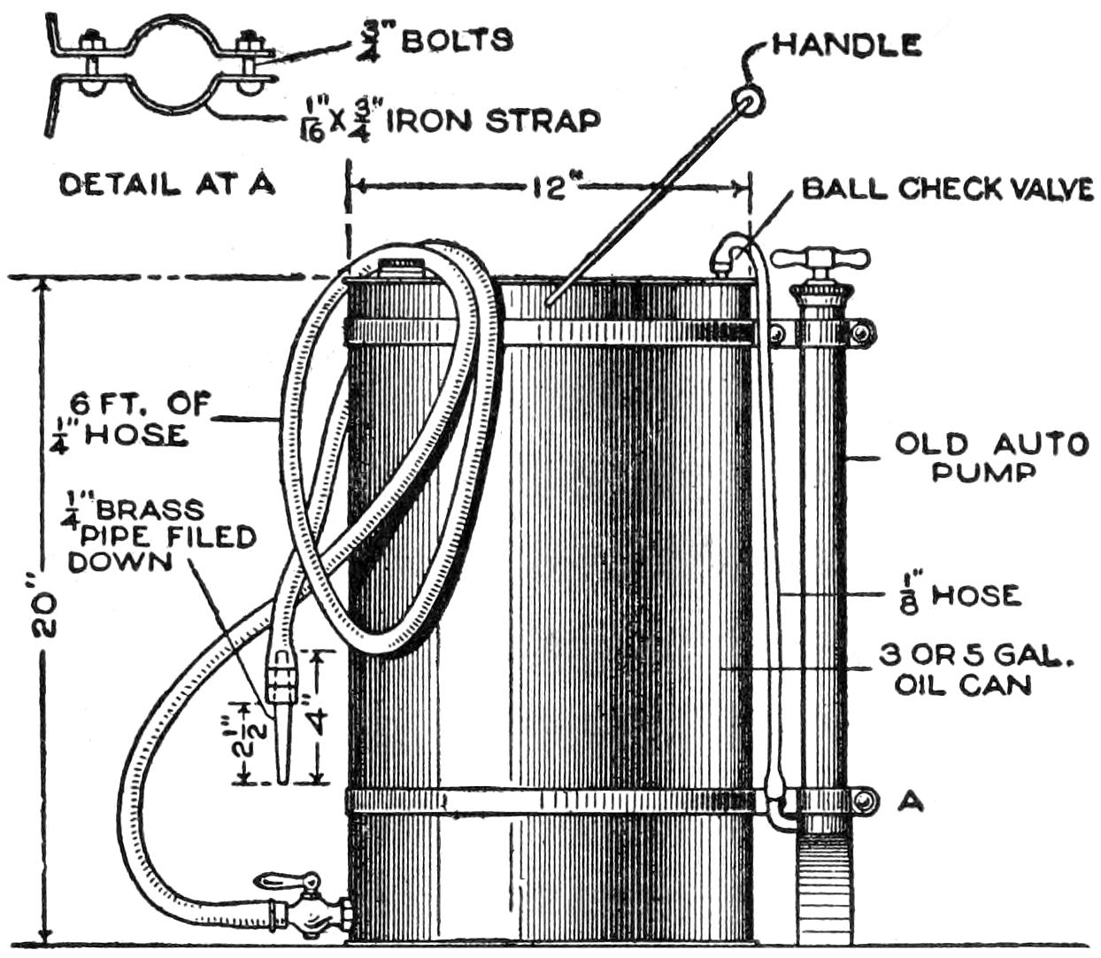
Old Material Makes a Spray That Is as Good as the Manufactured Product, at Less Cost
In making a spraying outfit for garden use, or similar purposes, a 3 or 5-gal. kerosene can and tire pump may be satisfactorily employed. The latter is attached rigidly at the rear of the container with iron straps, as shown. A ball check valve is fitted in the top of the receptacle and connection is made between it and the pump with the pump hose. A 6-ft. length of ¹⁄₄-in. rubber tubing is wired to the drain cock. An 8-in. piece of ¹⁄₄-in. brass pipe is filed down and wired in the spray end of the hose to serve as a nozzle.—P. P. Avery, Garfield, N. J.
Bright-finished tools can be preserved against rust by coating with linseed oil, and allowing the oil to dry as a film. If more body is desired, oxide of iron, very finely powdered, should be mixed with the oil. Another antirust coating is made by dissolving ¹⁄₂ oz. camphor in 1 lb. melted lard. The mixture is skimmed, and fine graphite added to make an iron color. Clean the tools and smear with this mixture. Let the tools stand 24 hours, and rub clean with soft cloth.
A good method of removing rust is to cover the metal parts with sweet oil, rubbing it in well. Let stand 48 hours; then rub with finely powdered, unslaked lime. Next immerse the article for a few seconds in a solution of ¹⁄₂ oz. potassium cyanide in a wine glass of water. Then clean with a paste of potassium cyanide, castile soap, whiting, and water, using a toothbrush. Potassium cyanide is a strong poison, and should be used carefully.—E. Standiford, Youngstown, Ohio.
Frequently a cast or malleable-iron pipe fitting will leak through its side, the water oozing, drop by drop, from a pinhole—ordinarily due to a sand hole in the casting. Sometimes the leak can be stopped by hammering the affected spot with the ball end of a hammer. If this fails, it is necessary to replace the fitting. Where the leak is around a thread, screwing the pipe or fitting tighter constitutes the only, and usually effective, corrective.—L. A. Merton, St. Louis, Mo.
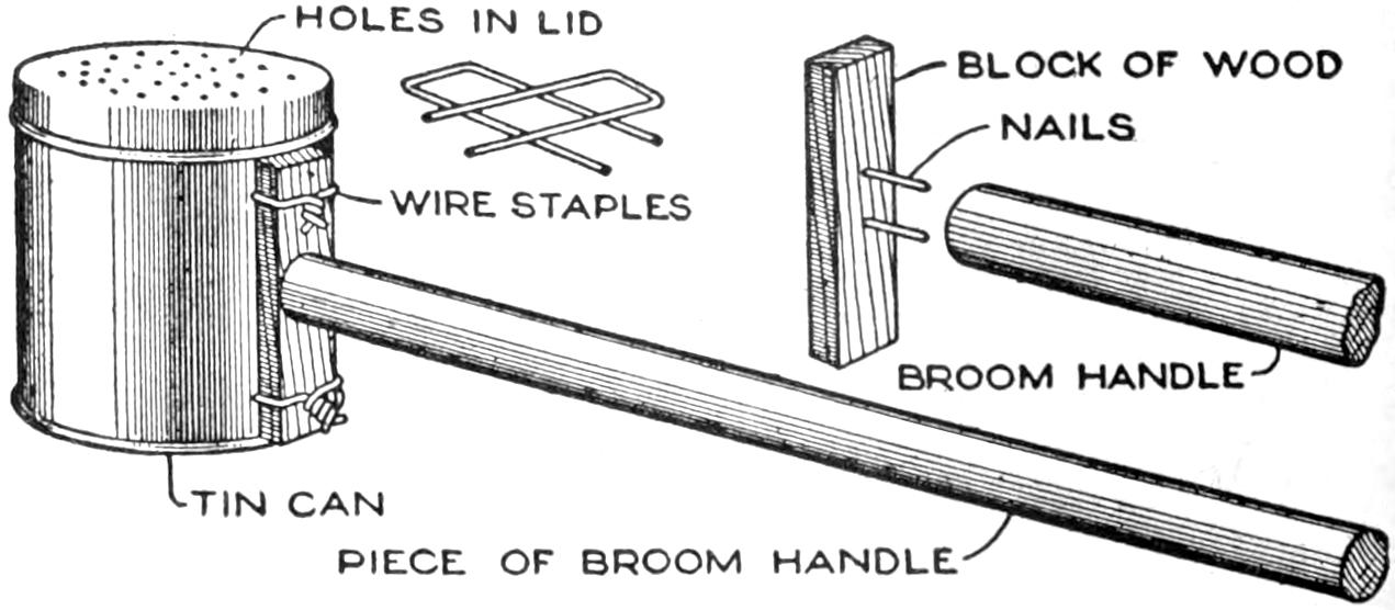
A Corn Popper Made from a Coffee Can, or Similar Tin Receptacle, and a Piece of a Broom Handle
With an old coffee can, or similar tin receptacle, and a piece of a broom handle, 2¹⁄₂ or 3 ft. long, it is easy to make a corn popper that is preferable in many ways to a wire one. Take a strip of wood a little shorter than the height of the can to be used, and after boring two holes in it to prevent its splitting, nail it to the end of the handle. The latter is then fastened to the side of the can with two wire staples, as shown. Holes are made in the can top to admit air to the corn while it is popping.—James Crouse, Dixon, Ky.
[213]
An anemometer is an instrument which measures the velocity of the wind. The anemometers used by the weather bureau consist of four hemispherical cups mounted on the ends of two horizontal rods which cross at right angles and are supported on a freely turning vertical axle. Since the concave sides of the cups offer more resistance to the wind than do the convex sides the device is caused to revolve at a speed which is proportional, approximately, to that of the wind. The axle, to which the rotary motion is transmitted from the cups, is connected to a dial mounted at the foot of the supporting column. This dial records automatically the rotations. The reproduction of such a registering mechanism would be rather complicated. Hence, in the arrangement to be described none will be employed. Therefore, one of these improvised anemometers, when mounted on a high building, will indicate by the changing rapidity of its revolutions only the comparative, not the real, velocity of the wind.
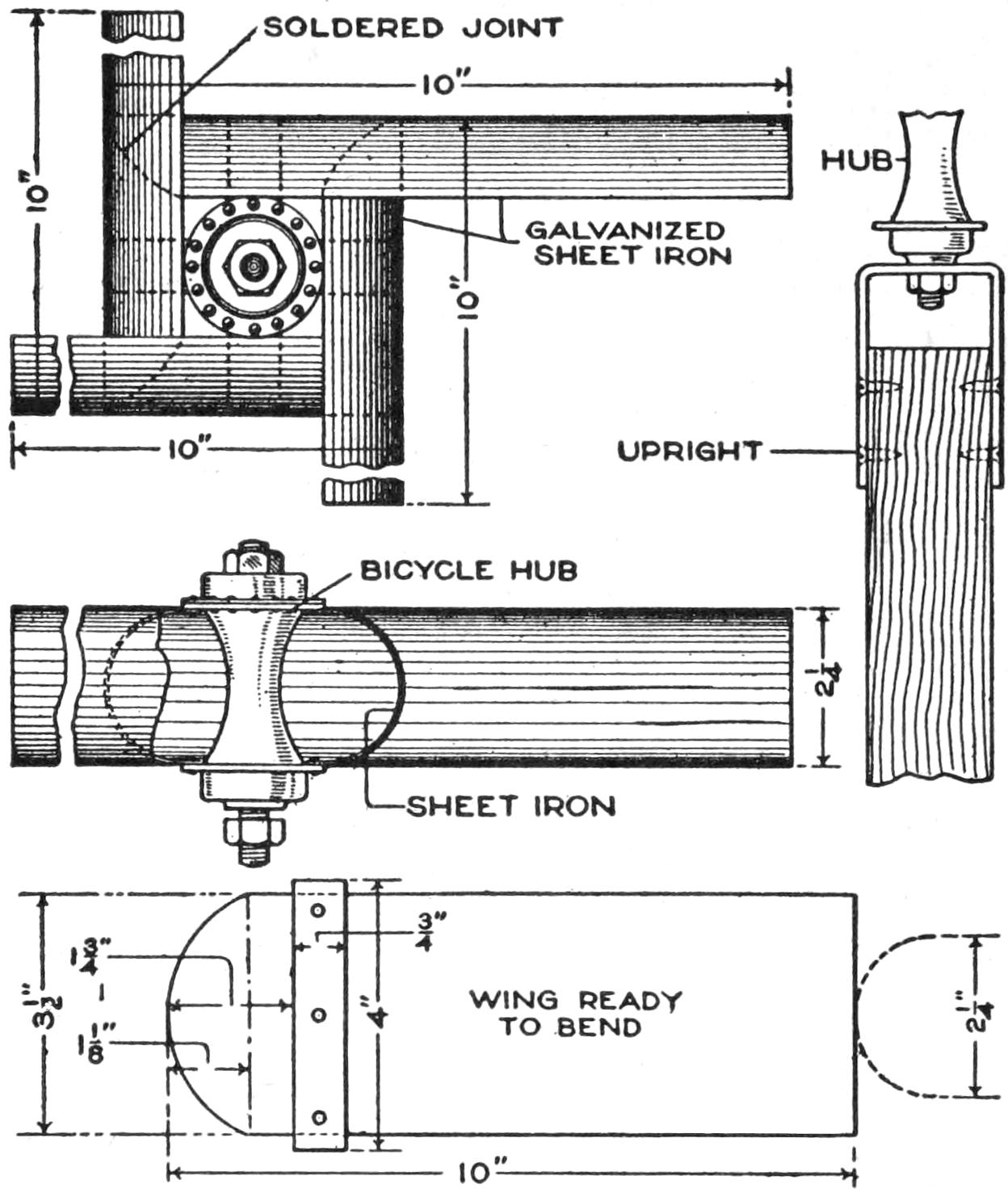
This Anemometer is Made from Galvanized Sheet Iron, a Bicycle Hub, and a Few Iron Straps. Practice in Observing Its Motion will Enable One to Estimate Fairly Closely the Wind’s Velocity
In constructing the instrument, straight, dished vanes will be used instead of hollow cups. The vanes operate almost as effectively and may be combined more readily into a sturdy rotating unit. A bicycle front hub is utilized to constitute a wear- and noise-proof bearing having minimum friction. Each of the four wings is formed from a piece of galvanized iron, measuring 4¹⁄₂ by 10 in., which has one end cut to a curve as shown. To each wing is fastened, with tinners’ rivets, a 4-in. length of ³⁄₄ by ¹⁄₁₆-in. strap iron. Form each of the strips into a trough-shaped vane, measuring 2¹⁄₄ in. from edge to edge—this being the distance between the spoke flanges of a bicycle hub. Some cylindrical object of suitable diameter will serve as a form for bending. Place the ends of the support strips between the spoke flanges and rivet them securely. The rivets pass through the spoke holes. Some trying out may be required to insure a symmetrical arrangement of the parts. Solder the curved end of each wing to the inner surface of the adjacent wing. Place a tin cap—a salve-box lid will do—under the upper locknut on the hub to exclude rain from the bearing.
The supporting upright may be a heavy wooden rod, or a piece of iron pipe. A yoke of 1 by ¹⁄₈-in. strap iron, held to the top of the upright with screws, is provided for the attachment of the hub. The locknut on the hub clamps it to the yoke. Apply a coat of metal paint to the iron parts which are exposed. Mount the device sufficiently high to give the wind free access to it from all directions. The curve at one end of each wing is an irregular one. Hence, its accurate construction involves a knowledge of sheet-metal pattern drawing. However, if it is made of a form similar to that shown it will fit sufficiently well to permit a good soldered joint.
¶Boards exposed to the weather should be laid with the heart side down, as determined by examining the end grain.
[214]
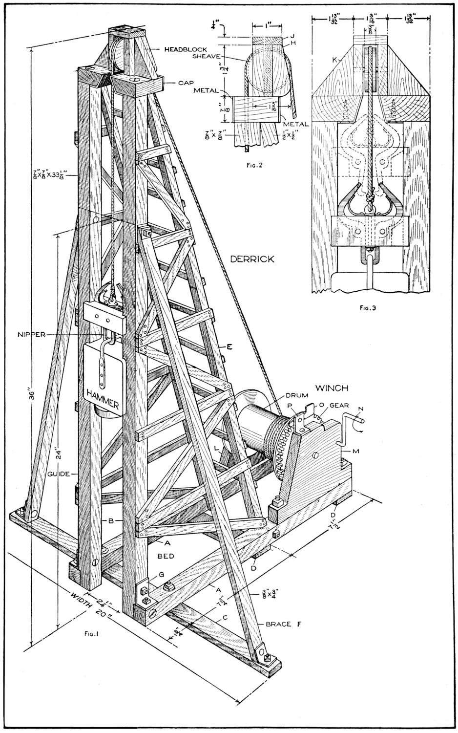
Fig. 2
Fig. 3
Fig. 1
Sharpened Poles, Two Feet Long, are Used with This Pile Driver in Building Foundations, Wharves, and Other Structures of Piling. The Details of the Headblock and the Nipper Device are Shown in Figs. 2 and 3
[215]
A Small Working Pile Driver
By EDWARD A. KRUEGER
[These directions will enable boys of varying skill with tools to make a pile driver, as a toy or model. Several simple methods of making the parts in the home workshop, with materials easily obtainable, are suggested.—Editor.]
The construction of small docks, wharves, piers, and foundations or bridges, buildings, and other structures, by the driving of piling is interesting out-of-door play, in which boys will find much fun. A pile driver for this work is shown in the page plate, Fig. 1. The hammer is raised by means of a winch, and is dropped automatically when it reaches the cap of the derrick, as indicated in Fig. 3. The drum is then released, and the weighted double-hook nipper drops down, picking up the hammer on the next upstroke. A single-hook nipper, that can be made easily of wire, is also shown in the detail sketch, Fig. 6. The small boy who cannot make the nippers or the winch, may tie the rope directly to the hammer, drawing it up by hand, and dropping it as desired. The hammer need not be fitted to the guides, but merely arranged to drop between them, and the derrick can be made of only a few main pieces. The larger parts of the hammer and nipper weight are best made of lead, babbitt, or white metal, as these may be cut or melted readily. Iron, brass, or copper, solid or in plates, may be used, if means for shaping them are at hand.
The making of the derrick may be undertaken first. Make two pieces for the bed A, ⁷⁄₈ by ⁷⁄₈ by 17 in.; two hammer guides B, ⁷⁄₈ by ⁷⁄₈ by 33¹⁄₈ in.; one bed piece, C, ³⁄₈ by ⁷⁄₈ by 20 in.; two bed pieces, D, ³⁄₈ by ⁷⁄₈ by 5¹⁄₄ in.; two posts, E, ¹⁄₂ by ¹⁄₂ by 34¹⁄₂ in.; two braces, F, ³⁄₈ by ³⁄₄ by 26¹⁄₂ in. Cut these pieces slightly over their finished lengths as given, allowing for trimming and fitting. Make strips, ¹⁄₄ by ¹⁄₂ in., for the bracing on the sides of the derrick and the ladder bracing on the back.
Notch the lower ends of guides B, ¹⁄₈ by ⁷⁄₈. and the lower ends of posts E, on an angle, ¹⁄₈ in. deep, to fit pieces A. Join the parts of the bed, as shown in the page plate, pieces A being set 3¹⁄₂ in. apart, fastening them with bolts or screws. Make braces G, of sheet metal, and bolt them in place. Fit the posts E into place, and fasten them at the bed and the top. Put on several ladder braces temporarily, to steady the frame. Fit the braces F carefully, and bolt them in place. Remove the piece C and the braces F, and nail the horizontal bracing to the sides of the frame. Then fit and nail the diagonal braces. The bolted construction is convenient in “knocking down” the derrick for storing it. Reassemble the parts, and make the cap for the headblock.
The headblock and cap are shown in detail in Figs. 2 and 3. Make two pieces, H, ¹⁄₄ by 1⁵⁄₁₆ by 1³⁄₄ in.; one piece, J, ¹⁄₄ by 1 by 1³⁄₁₆ in.; two braces, K, ¹⁄₄ by 1¹³⁄₃₂ by 1³⁄₄ in. Make the two beveled pieces of the cap ⁷⁄₈ by 1³⁄₄ by 1¹⁄₂ in., and provide a wooden strip or metal plate for the front and rear edges, as shown. Fasten strips of sheet metal to the bevel of the notch, to protect it from wear by the striking of the nipper hooks. Make the sheave 1¹⁄₂ in. in diameter and ³⁄₈ in. thick, with a groove for the rope. Assemble the parts, as shown.
The details of the winch are shown in Figs. 4 and 5, and the method of assembling the parts, in Fig. 1. The[216] drum may also be driven without gears by fixing the crank directly to the shaft. Gears may be obtained from old machines, or purchased from dealers in model supplies. Make the supports L and M, Fig. 4, ³⁄₄ by 4 by 6⁵⁄₈ in., cutting patterns of paper, if desired.
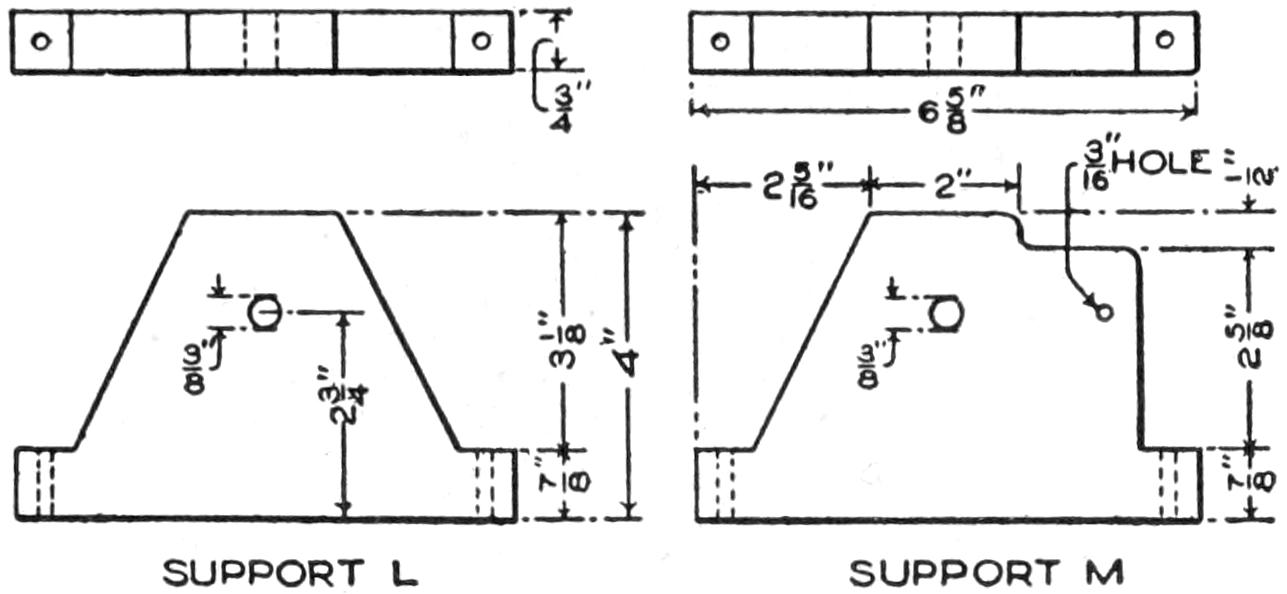
Fig. 4
The Supports of the Winch are Made of ³⁄₄-Inch
Wood, Bolted to the Bed
The gear, Fig. 5, is 3¹⁄₂ and the pinion ³⁄₄ in. in diameter. The drum is of wood, 2 in. in diameter and 3⁵⁄₁₆ in. long. Its ends are 3¹⁄₂-in. metal disks, fastened with screws. The shaft is a ³⁄₈-in. bolt, 5³⁄₈ in. long, and bears in holes bored in the supports, as shown in the details of these parts. The crank N, Fig. 5, is made of a ³⁄₁₆-in. rod, bent as shown, and fitted with a washer to fit next to the pinion. The gear is set by means of the pawl O, which is bent from a strip of ¹⁄₁₆-in. sheet metal. The brace P is bent from a ¹⁄₁₆ by ³⁄₄ by 1⁵⁄₈-in. strip of sheet metal, and riveted to the pawl. Assemble the parts, fastening the gear to the drum end, and bolt the supports into place. Put the pinion into mesh with the gear at its proper place, and carefully mark the hole for the crank. Square the end of the crank and the hole in the pinion, and fit them to a driving fit. Fix the rope to the drum, and reeve it through the head block. The derrick is then ready for the hammer and the weighted nipper.
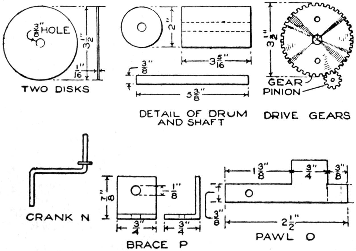
Fig. 5
Details of the Drum, Its Driving Mechanism,
and Fittings
The hammer, shown in Fig. 6, may be made easily from a solid block of lead, 1¹⁄₄ by 2⁵⁄₈ by 2⁵⁄₈ in. Cut ³⁄₁₆ by ⁷⁄₈-in. grooves in the vertical edges to fit the guides. Make the circular ³⁄₁₆ by 1⁵⁄₈-in. hammer plate Q of iron or brass, and fasten it with screws. Rivet the wire lifting strap R, as shown.
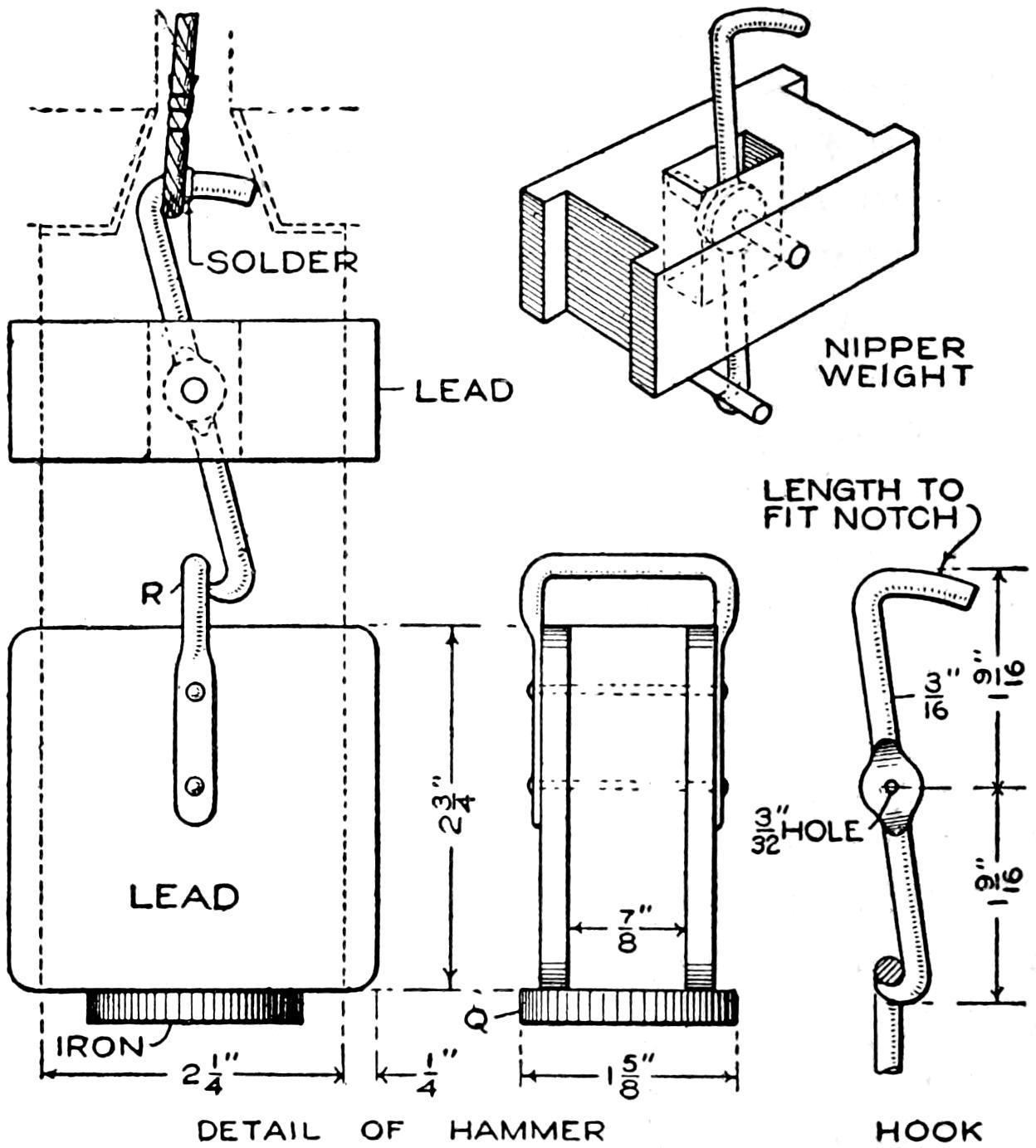
Fig. 6
A Simple Method of Making the Tripping Device,
and Details of the Hammer
The single-hook nipper, shown in Fig. 6, is made as follows: Flatten a piece of ³⁄₁₆-in. wire at the middle, and drill a ³⁄₃₂-in. hole for the bolt. Shape the lower end into a pointed hook, and bend the upper end to form the trip arm. This strikes the notch in the cap of the derrick, releasing the hammer. The rope is wired to the hook as shown. The nipper weight is made of a solid piece of lead, 1¹⁄₄ by 2⁵⁄₈ in., by 1 in. high, grooved at the ends to fit the guides. Cut a slot through it, for the hook, as shown in Fig. 6, and bolt the latter into place. The double-hook[217] nipper is better mechanically, and may be made of two pieces of wire, or cut from sheet metal.
Test the action of the nippers, and bend or file the hooks to operate properly. The pile driver may then be painted, and work on “jobs” begun. If it is used at the water, fix metal guards at the lower ends of the guides, to prevent the hammer from falling into the water.
An amusing stunt is to split the end of a fiber talking-machine needle carefully about ¹⁄₄ in., so as to make two points, slightly separated. The needle is then placed on the machine, preferably on an old record, so that the points play the record successively, producing an echo. If the work is carefully done, and the points are separated slightly, both reproductions will be fairly clear.—Frank Murphy, Faribault, Minn.
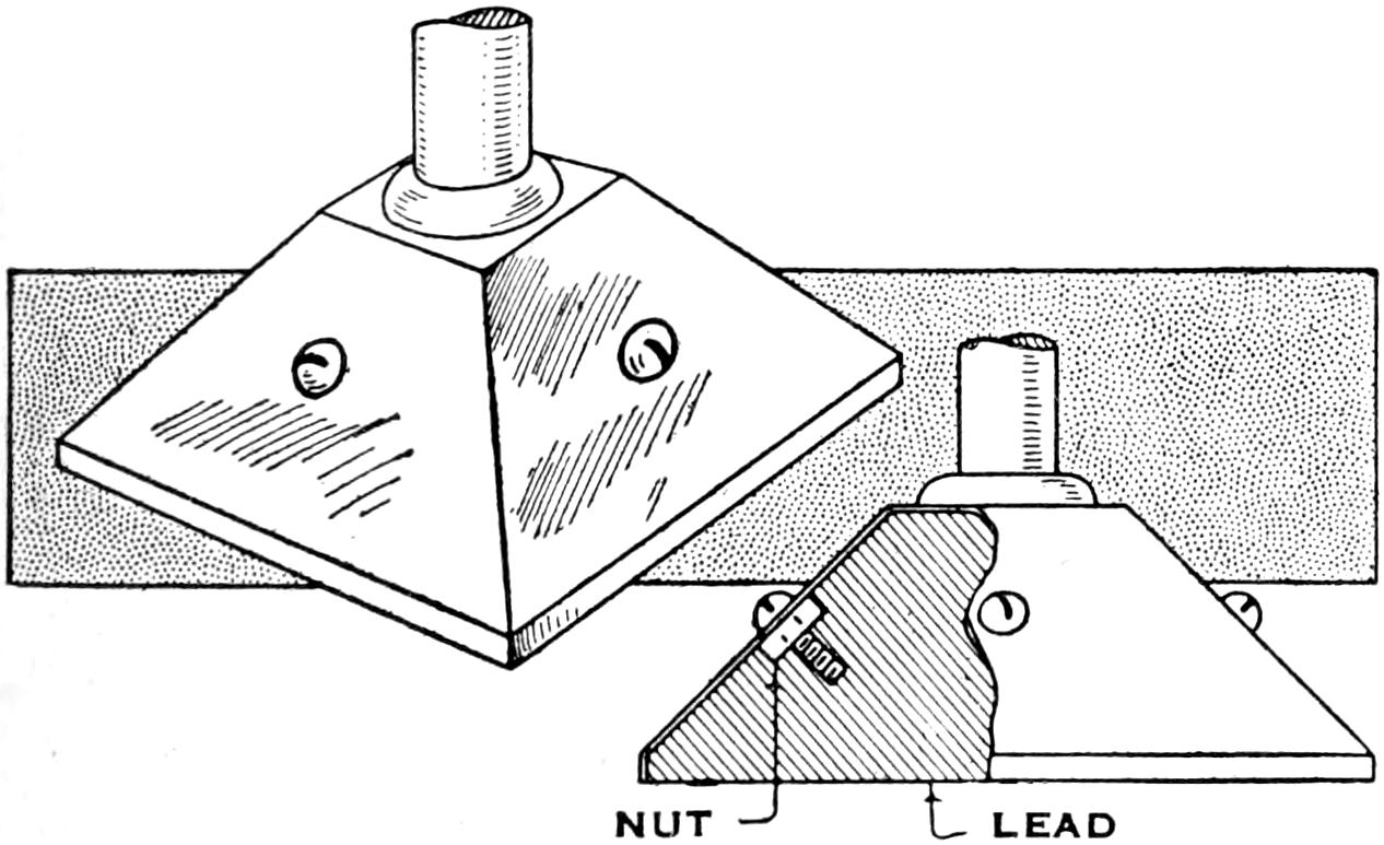
Molten Lead as Poured In around Screws Fastened to the Base
Having to weight a shallow metal base to support a 4-ft. brass tube, I found that the easiest way was to fasten four screws on the base with nuts, as shown in the illustration, and pour in lead. The screws were taken out in polishing the base.—James M. Kane, Doylestown, Pa.
¶In toasting bread over a camp fire, it is best to cover the fire with a tin pan.
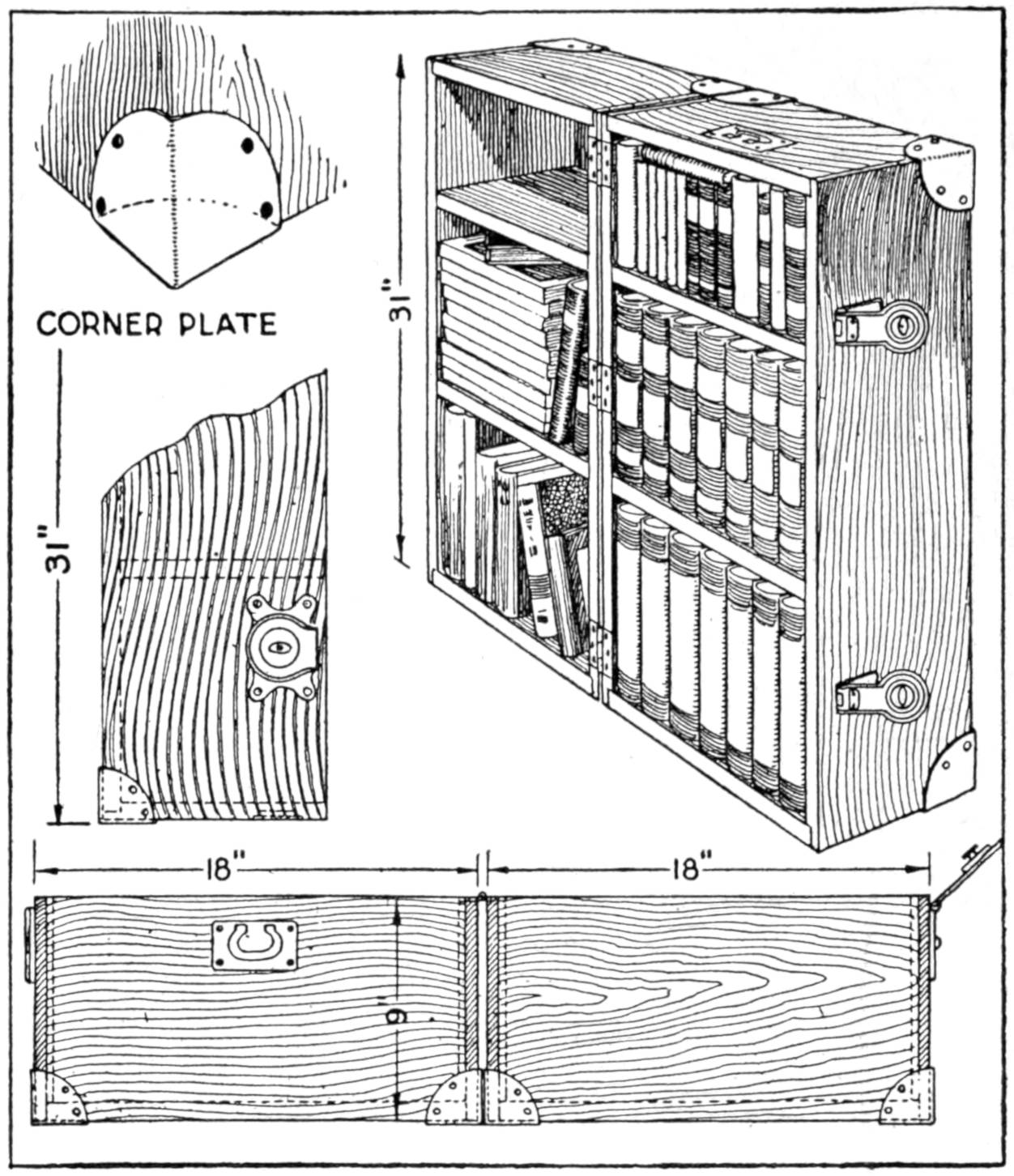
A Small Library may be Shipped Handily in This Bookcase
Mechanics, engineers, and other persons are sometimes engaged in work which keeps them at the same locality only a few months. Those who desire to carry with them a small library will find the trunk bookcase, as shown, convenient. It may be shipped as a trunk, and used as a bookcase in one’s hotel or dwelling. Other articles than books may be packed in it. The outside dimensions when closed are 31 by 18 by 18 in., providing for three shelves. It may be made of ³⁄₄-in. pine or whitewood, and stained, or covered with impregnated canvas. The outer corners are reinforced with metal corner plates, and suitable hardware is provided.—Lloyd C. Eddy, Jr., Buffalo, N. Y.
Two metal pipe straps, fitted around the neck of a bottle and bolted together, form a convenient method of attaching a carrying handle to a large bottle. The handle proper is made by fixing a grip in a bail of wire similar to that on a bucket.
[218]
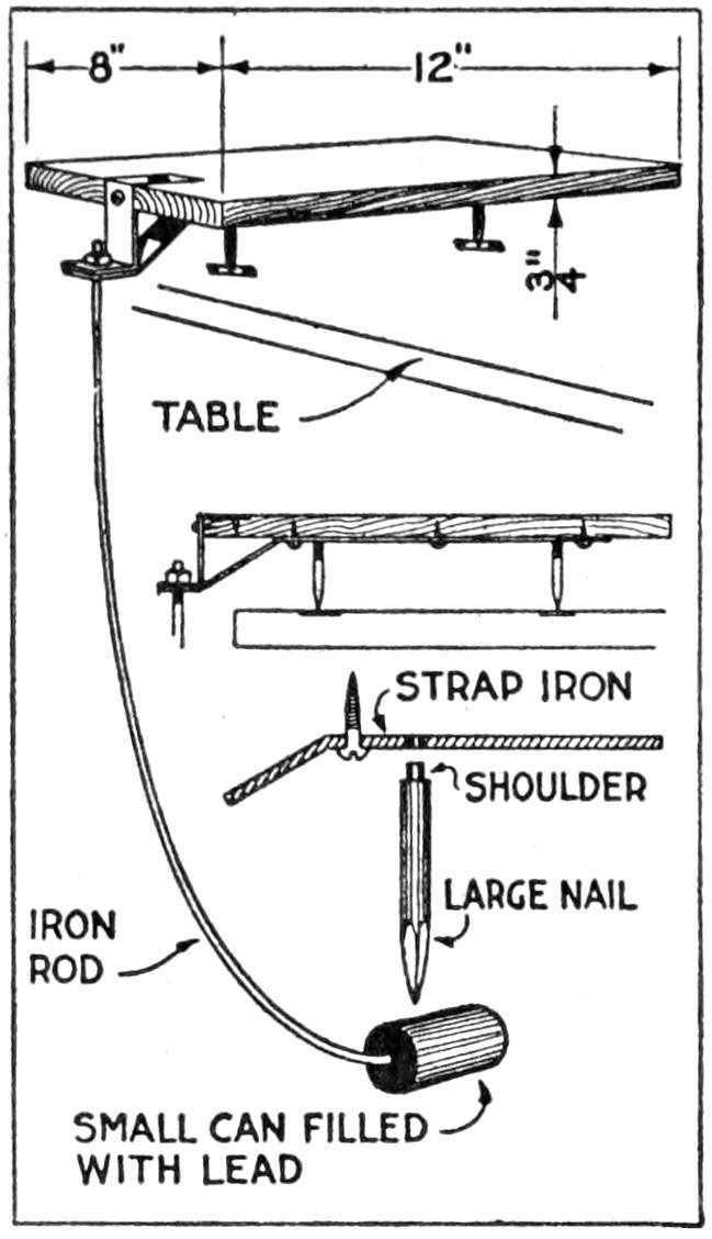
An appliance that saves time for the worker in a photographic dark room is a tray rocker, made as follows: Fasten a bracket of strap iron, into which are riveted the pointed ends of two spikes, to the under side of a board, as shown in the detail sketch. Support this further with a double angle fastened at the end of the board. Fix a small can, weighted with lead, on the end of an iron rod, adjusted to a suitable curve, and fasten the rod to the bracket. The weighted end should extend under the edge of the table, as shown, and be balanced so that it will rock the board and tray without tipping the latter toward the bracket. The nails pivot on metal pieces, to protect the table top.—L. L. Llewellyn, Piedmont, Calif.
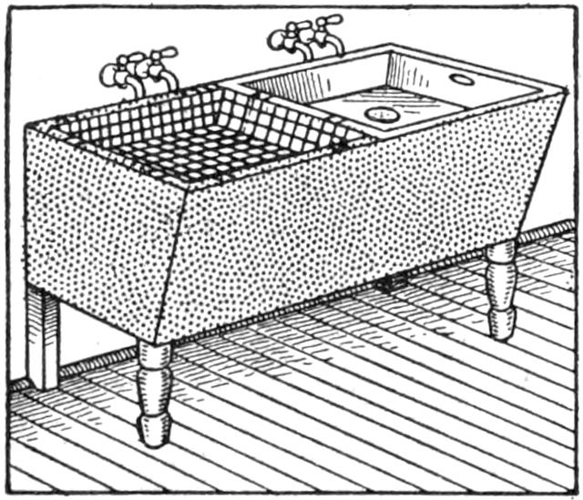
A saving of space and time was effected in a home kitchen by the use of a sink developed in a large kitchen. Two ordinary laundry tubs were installed with the faucets raised above the tubs, as shown. A sink of sheet zinc was fitted in the upper part of one tub; it has handles, and a strainer set in the bottom. The strainer is closed by a rubber stopper, and the sink becomes a dishpan. The sink is easily lifted out for cleaning, or for washing clothes. Another use for the sink, between meals, is for washing and preparing vegetables and fruits. The second tub has a wire dish-draining rack, in which the china is rinsed and sterilized by hot water from the faucet.—Mrs. Avis Gordon Vestal, Chicago, Ill.
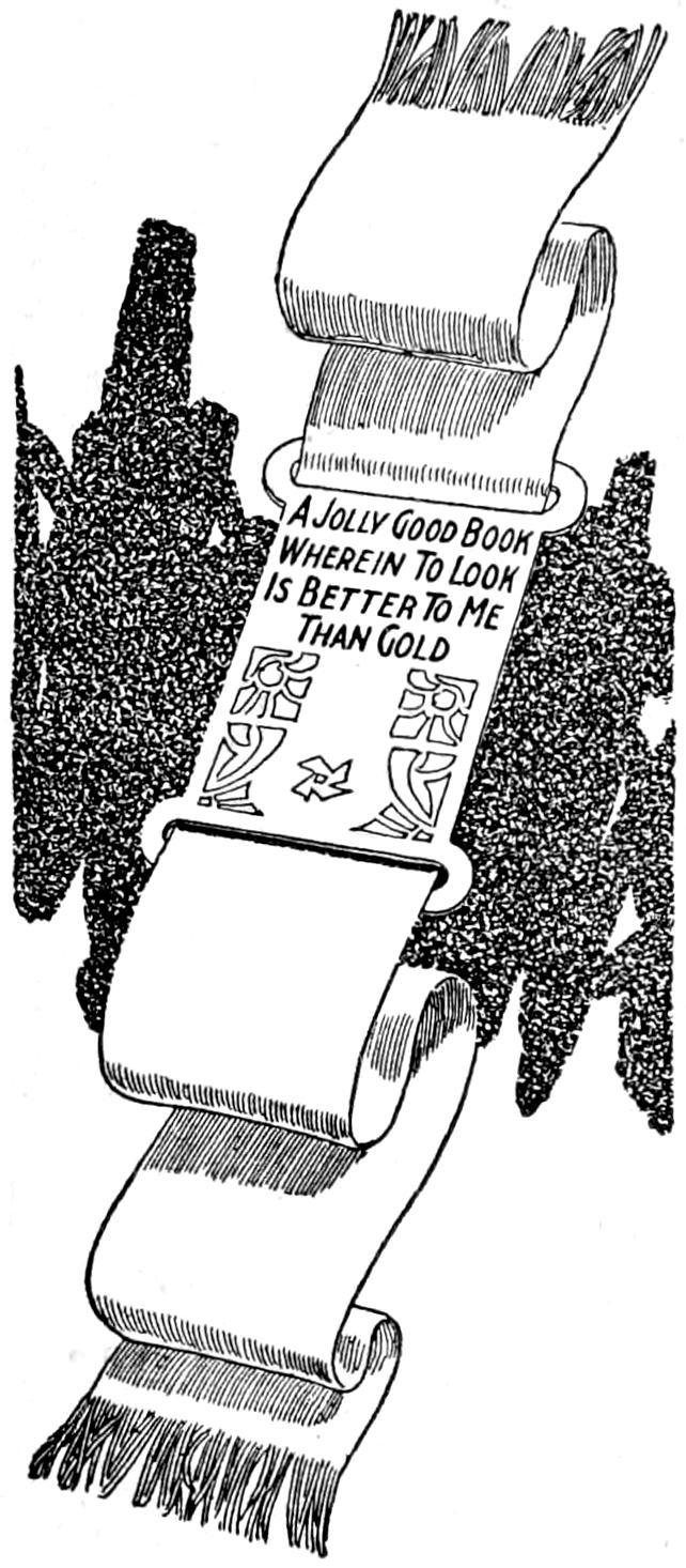
A Jolly Good Book
Wherein To Look
Is Better To Me
Than Gold
An artistic and useful bookmark was made from a silk ribbon passed through a buckle of leather, tooled with an inscription and a conventional design. Ribbon of various sizes may be used, and the leather left plain if desired. The ends of the ribbon are fringed, as shown. Monograms make interesting and individual decorations for the leather portion.—Will Chapel, Manchester, Ia.
An oarlock that will give considerable service may be made by fixing a loop of rope to the gunwale of a boat at the proper position. This kink is useful in an emergency, such as when an oarlock is dropped overboard.
Boys who make thin sticks for arrows, kites, etc., as well as the mechanic, can make good use of the following suggestion: The difficulty of handling thin strips while planing them may be overcome by setting the strip in the groove of a piece of flooring, clamped in a vise. A peg or nail is driven into the groove and acts as a stop for the end of the strip.
[219]

A Submarine Camera
by Charles I. Reid
Submarine photography should have great attractions for amateur photographers who have access to lakes, ponds, and other clear waters. While more careful work is demanded than in ordinary photography, the method of obtaining good results is not difficult, and the necessary equipment may be provided by constructing the device shown in the illustration. Submarine pictures can be taken in a considerable depth of water, providing it is reasonably free from foreign matter. This is a fascinating field of photography, and many pictures of educational and scientific value remain to be made of under-water life. The illustration shows the detailed construction of the camera chamber, and the method of suspending it from a bridge, or other place convenient to the body of water. Reproduced in the oval panel is a photograph of fish near baited hooks, on a fishline. The original was made from a negative exposed by the use of the camera chamber described.
The problem of making photographic exposures under water involves the provision of a strong water and pressure-proof container for the camera, a means for controlling the shutter, and a suitable opening in the container through which the exposures may be made. The arrangement described combines these features in a simple manner, and by the use of materials that can be obtained without difficulty. It was made for a camera taking 4 by 5-in. pictures, and the dimensions given are for a container for this size. The dimensions may be varied to adapt the device to various cameras, within reasonable limits. A 9-in. steel pipe was used for the chamber, and its ends were fitted with pipe caps. A heavy piece of plate glass was fitted into the forward cap, which was cut into the shape of a ring, to provide the exposure opening. The general arrangement of the camera in the chamber is shown in the sectional view, Fig. 1, as seen from the shutter end. The electrical device, by which the shutter is controlled, is shown in this view, and in Fig. 2 it is shown in detail.
The chamber was made as follows: A section of 9-in. steel pipe was cut to a length of 11¹⁄₂ in. and threaded on the ends to fit pipe caps. The forward pipe cap was chucked up in a lathe and the center portion cut away, to provide an exposure opening and a shoulder at the rim, on which the plate-glass window rests. A graphite paint was applied to the rim, then the glass was bedded solidly in it, and a rubber gasket was fitted to the joint, making it waterproof when the cap was drawn up tightly. The chamber assembled and in detail is shown in the illustration.
Holes were bored into the top of the chamber, and eyebolts were fitted into them. Between the eyebolts a hole was bored and fitted with a water-tight collar, through which the wires leading to the shutter-control device pass. The chamber is supported by the wires, which are fixed to the eyebolts and secured at the base of operations by the photographer.
A support for the camera was provided by bending a strip of ¹⁄₈ by 1-in. band iron to the shape indicated in Fig. 1, at A, and riveting it to the bottom of the chamber. Its upper surface is flat and was bored and threaded to fit the tripod thumbscrew B, on the lower surface of the camera. The camera is arranged on the support and clamped into place firmly by the thumb nut, as it might be on a tripod. The adjustment of the camera in the chamber is done from the rear, and the space beneath the thumbscrew should be large enough to make access easy. A camera of the size indicated, when fitted with its lens centering on the center of the window, will be raised sufficiently for[220] convenience in clamping it. The threads on the back cap must fit snugly and no paint must be used on them. Hard oil, or vaseline, may be applied to insure a water-tight joint that permits easy removal of the cap.
The making and adjustment of the electrical shutter device requires care, but its operation is simple. An electromagnet, of the type used on doorbells, was fixed to the front of the camera, above the shutter, as shown in Fig. 1, and in detail in Fig. 2. It is actuated by current from two dry cells. The latter are kept in a convenient carrier at the base of operations, and are connected to the magnet by a single strand of double, waterproof wire. This is spread as it reaches the chamber and fastened to the two eyebolts in the top. The ends of the wires are conducted through the water-tight center opening between the eyebolts, and attached to the magnet. The release lever is fitted to a steel hook, pivoted at its upper end with a small nail, C, Fig. 2. A rubber band is fixed to the lower edge of the shutter lever and its other end is attached to the front of the camera. When the current is permitted to flow into the magnet by pressing a contact key, in the hand of the operator, the steel hook is drawn from the release lever, and the rubber band draws the lever down, making an exposure.
The double-wire cable carries the current as well as holds the chamber suspended in the water. The wire should be about 25 ft. long, and, in transporting the outfit, or when only partly used, is coiled. The chamber should be completed for picture-taking operations by giving it a coat of dull, black waterproof paint, both inside and outside. This will prevent rusting and also serves to make the object inconspicuous when in the water. It is important that the interior be painted in this manner, because reflections of light within the chamber may cause difficulty in obtaining satisfactory results. When the paint is thoroughly dry, the device may be tested for leakage and assembled ready for a test before making an actual trial in the water. The camera is fitted into the chamber so that it centers on the center of the plate-glass window, and is clamped into place. If the electrical device operates satisfactorily the plate may be inserted, the plate-holder slide withdrawn, the back cap replaced securely, and the outfit lowered into the water. It should be watched carefully until it reaches the proper depth, for, if it is permitted to touch the bottom, the sediment stirred up must be given time to settle before an exposure is made. The forward end of the chamber should be marked on its upper edge with a streak of white paint, to aid in identifying it at considerable depth in the water. This is important, since the operator must shift the chamber carefully until the window faces the objects to be photographed. When the chamber is in position, the contact key is pressed and the exposure is made.
The time of exposure for under-water photography depends on the clearness of the water, the depth at which the pictures are to be taken, and the light conditions on the surface. A bright day is, of course, desirable for this class of photography. A safe approximation on a sunny day, in clear water, and with the chamber lowered to a depth of 20 ft., is ¹⁄₂₅ sec. at the F 8 stop. The fastest plates or films obtainable should be used for this work, making possible a fairly rapid shutter speed. This tends to overcome the movement of the subject and possible movement of the camera.
The camera should be focused while in the chamber in order that the plate glass may not disturb the focus. The glass usually changes the focal length of the lens slightly, hence this precaution must be taken. The camera should be focused in the chamber for a distance of 10 ft., as this is the average at which under-water photographs will be taken ordinarily.
When attempting under-water photography in cloudy waters, or at a considerable depth, the necessary illumination may be provided by a charge of flash-light powder. For this purpose another submarine chamber, similar to that used for the camera, should be provided, with a plate glass, ¹⁄₂ in. thick, and a valve fitted into the top of the chamber, and opening outward, so that the gas may escape. Fifteen grains of powder will suffice, and this should be set off by a small electrical fuse connected to the current supply.
[221]
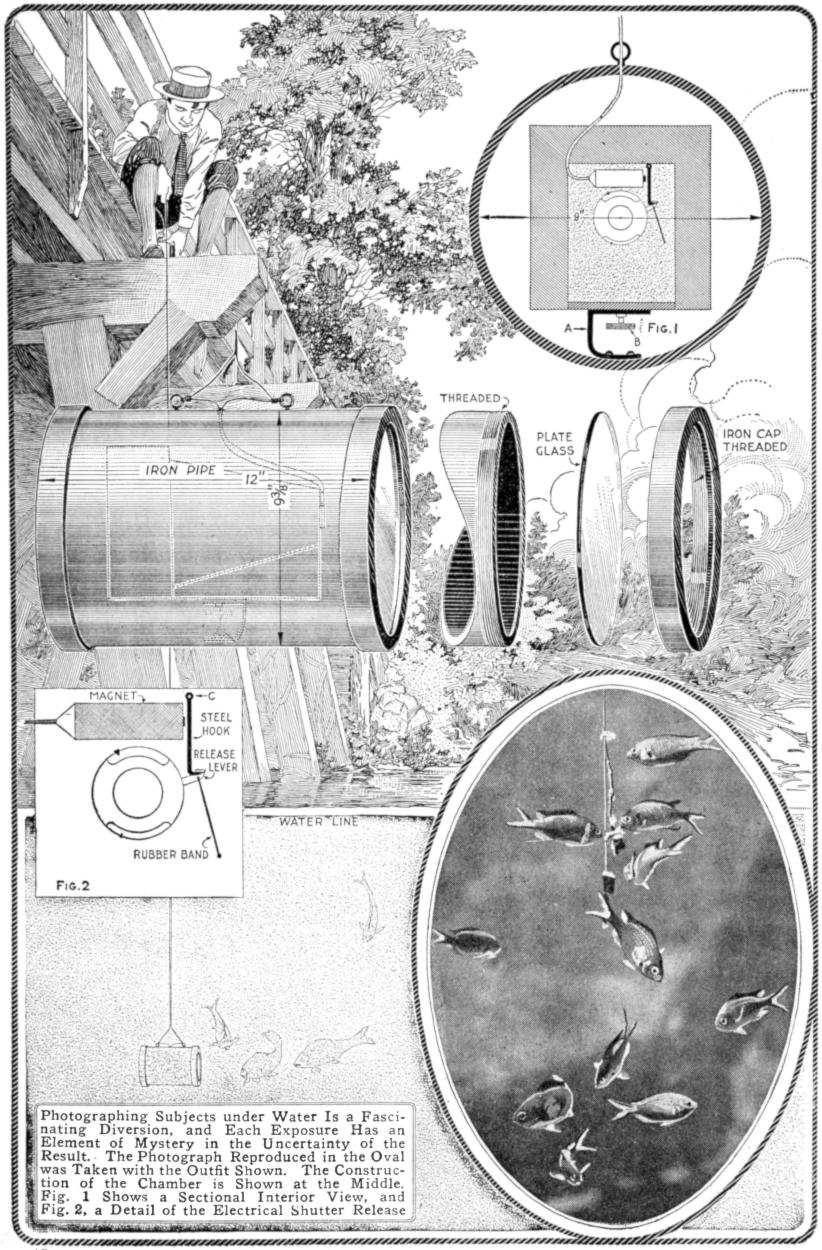
Fig. 1
Fig. 2
Photographing Subjects under Water Is a Fascinating Diversion, and Each Exposure Has an Element of Mystery in the Uncertainty of the Result. The Photograph Reproduced in the Oval was Taken with the Outfit Shown. The Construction of the Chamber is Shown at the Middle. Fig. 1 Shows a Sectional Interior View, and Fig. 2, a Detail of the Electrical Shutter Release
[222]
Every pond, lake, and river abounds in interesting and instructive subjects for submarine photography. Along the coast of Florida, and at many points along the Pacific coast, are waters of such clearness that pictures may be taken at a depth of nearly a hundred feet, without the use of artificial illumination. These localities abound in objects under water of great interest, such as shipwrecks. The fascinating art of taking pictures under water does not make it necessary for one to go to these places, for subjects are easily available. Whenever the submarine chamber is raised from the water there is an element of mystery involved, regarding what may be recorded on the plate or film, and this is an attractive feature of the diversion.
That there are a great many magic squares; that the numbers in these squares are arranged according to a definite system; that squares with very remarkable properties are easily constructed, are facts not generally known.
Consider the magic square A of 16 numbers. Add up any four numbers straight across, up and down, or diagonally—10 ways in all—and the sum in each case will be 34. But that is not all: Take the four numbers in any one quarter of the square, as for example, 15, 10, 4, and 5, and the sum will be 34; or take the four central numbers, or the four corner numbers, and the result will be the same. But even this does not exhaust the magic of the square. Add any four numbers arranged symmetrically around the center, as 3, 10, 8, and 13, or 10, 4, 7, and 13, and the result will also be 34. In fact, it is really not necessary to have them arranged symmetrically, because it will be found that four numbers arranged as are 6, 10, 11, and 7, or 1, 4, 16, and 13 will produce the same magic number of 34.
There are two other combinations of the 16 numbers that will give the same result. They are shown at B and C. In fact the second one, B, not only exhibits some of the former combinations, but also includes such sets of four as 14, 5, 3, and 12, or 15, 8, 2, and 9, which places to the credit of this square numerous combinations. Such special features as this simply add another element of mystery and interest. Thus, while the square B has these two combinations exclusively to its credit, the first, A, and the third, C, have such special arrangements as 5, 16, 1, and 12, or 15, 6, 11, and 2. Also 10, 3, 5, and 16, or 4, 5, 14, and 11, making the total number of such combinations for the first square 34.
Magic squares of 25 numbers also have remarkable properties. Examine the square D and note the many possible combinations graphically set forth in the small diagrams. Not only do any five numbers in a row or along a diagonal make 65, but almost any four arranged around the center, with the center number 13 added, will give the same result.
This square is a good example by which to illustrate one of the methods of construction of these interesting devices. Thus, place 1 in the middle square of the top row, and then write the numbers down consecutively, always working in the direction of the arrows as indicated. When any number falls outside, as number 2 does at the start, drop down to the extreme square in the next row and insert the number there, as was done in this case. It will be observed that 4 falls outside, and so it is moved to the proper square[223] as suggested, which will be at the extreme left of the next row above. Continuing, it is found that at 6 it is necessary to drop down one square and continue in the direction of the arrows. At 9 it is necessary to drop down to the proper extreme square as shown. The next number, 10, must again be provided for at the square on the left of the next higher row. The square ahead being already filled, 11 is placed below; after this there is “clear sailing” for a time. In this manner magic squares with seven or nine numbers to the side may be made easily. When puzzles and catch problems are under discussion, it is always mystifying to take one’s pencil and quickly make out a magic square according to this easily remembered method. The small diagrams at D suggest some of the combinations.
Another method of constructing a square of 25 numbers diagonally is shown at E. Place the outside numbers in the open spaces at the opposite side of the square, maintaining the same triangular relation, which results in the arrangement shown at F. While this combination is entirely different from the previous one, it exhibits the same mysterious properties.

| 15 | 10 | 3 | 6 |
| 4 | 5 | 16 | 9 |
| 14 | 11 | 2 | 7 |
| 1 | 8 | 13 | 12 |
A
| 1 | 15 | 14 | 4 |
| 12 | 6 | 7 | 9 |
| 8 | 10 | 11 | 5 |
| 13 | 3 | 2 | 16 |
B
| 9 | 7 | 14 | 4 |
| 6 | 12 | 1 | 15 |
| 3 | 13 | 8 | 10 |
| 16 | 2 | 11 | 5 |
C
| 17 | 24 | 1 | 8 | 15 |
| 23 | 5 | 7 | 14 | 16 |
| 4 | 6 | 13 | 20 | 22 |
| 10 | 12 | 19 | 21 | 3 |
| 11 | 18 | 25 | 2 | 9 |
4 COMBINATIONS 6 COMBINATIONS
D
| 1 | ||||||||
| 6 | 2 | |||||||
| 11 | 7 | 3 | ||||||
| 16 | 12 | 8 | 4 | |||||
| 21 | 17 | 13 | 9 | 5 | ||||
| 22 | 18 | 14 | 10 | |||||
| 23 | 19 | 15 | ||||||
| 24 | 20 | |||||||
| 25 | ||||||||
E
| 11 | 24 | 7 | 20 | 3 |
| 4 | 12 | 25 | 8 | 16 |
| 17 | 5 | 13 | 21 | 9 |
| 10 | 18 | 1 | 14 | 22 |
| 23 | 6 | 19 | 2 | 15 |
F
| 4 | 25 | 18 | 11 | 7 | 11 | 24 | 2 | 20 | 8 | 17 | 6 | 5 | 23 | 14 |
| 14 | 20 | 2 | 17 | 12 | 9 | 12 | 25 | 3 | 16 | 3 | 24 | 12 | 16 | 10 |
| 5 | 10 | 13 | 16 | 21 | 17 | 10 | 13 | 21 | 4 | 11 | 20 | 8 | 4 | 22 |
| 23 | 9 | 24 | 6 | 3 | 5 | 18 | 6 | 14 | 22 | 9 | 2 | 21 | 15 | 18 |
| 19 | 1 | 8 | 15 | 22 | 23 | 1 | 19 | 7 | 15 | 25 | 13 | 19 | 7 | 1 |
G
| 30 | 39 | 48 | 1 | 10 | 19 | 28 |
| 38 | 47 | 7 | 9 | 18 | 27 | 29 |
| 46 | 6 | 8 | 17 | 26 | 35 | 37 |
| 5 | 14 | 16 | 25 | 34 | 36 | 45 |
| 13 | 15 | 24 | 33 | 42 | 44 | 4 |
| 21 | 23 | 32 | 41 | 43 | 3 | 12 |
| 22 | 31 | 40 | 49 | 2 | 11 | 20 |
H
The Magic Squares Shown Afford Much Interest to the Experimenter in Such Devices: The Mastery of the Principle Underlying Some of Them will Enable One to Mystify and Interest Onlookers, with Little Chance of the Simple Method being Discovered
Although they do not contain quite so many combinations, the three magic squares shown at G all add up to this same magic number of 65, straight across, diagonally, and many other ways. A square with seven numbers to the side, worked out according to the first method described, is illustrated at H. The magic number here is 175. Since the general principle is similar to that involved in the squares described in detail, the working out of the numerous combinations of the squares shown at G and H will be left to the interested experimenter.
When a watch is used on a table in the sick room, the ticking may be eliminated by placing an ordinary tumbler over the watch. The face may be seen readily. A large glass vessel, or transparent jar, may be used in the same way to cover a small clock.—L. E. Turner, Jamaica, N. Y.
¶To letter on prepared cloth, use colors ground in japan and thin the mixture with gasoline to the consistency of cream.
[224]
Have you ever needed a secret code in which to couch the contents of a message intended for the eyes of one person alone? If you have, you will remember the difficulties that were experienced in making up the code and enciphering your letter. Here is a cipher code that may be mastered in a few minutes; one that is most difficult to decipher by any person other than those having the key words, and that is very simple when once understood.
| G | R | A | N | T |
| F | IJ | E | L | D |
Fig. 1
| G | R | A | N | T |
| B | C | H | K | M |
| F | IJ | E | L | D |
| O | P | Q | S | U |
| V | W | X | Y | Z |
Fig. 2
| C | H | A | IJ | R |
| B | D | E | F | G |
| K | L | M | Q | S |
| O | P | T | U | N |
| V | W | X | Y | Z |
Fig. 3
The Cipher Code Illustrated in These Diagrams may be Adapted for Wide Uses by the Substitution of Appropriate Key Words for Those Shown
It is commonly known as the “Play Fair” code and is in use in some of the foreign military services. It is a substitutive cipher which operates with one or more key words, two letters in the code being substituted for each two letters in the text of the message. In preparing the cipher code by this method the key words are selected by the correspondents and their location in the cipher square mutually agreed upon. A large square divided into 25 smaller squares is drawn, as shown in Fig. 1, and the letters of the key words entered into their proper spaces, the remaining spaces being filled by other letters of the alphabet. The key words must not contain duplicate letters. The letters I and J are considered as one and entered in the same space, the letter I being invariably used in enciphering.
Suppose that the two words “grant” and “field” have been selected for the key, the same to be entered respectively in the spaces on the first and third horizontal lines of the square. Then the basis of the construction would be as indicated in Fig. 1. Now fill in the remaining fifteen spaces of the square with other letters of the alphabet, beginning at the blank space at the left of the second line, entering the letters in rotation and not using any letter of the key words. The completed cipher would then appear as shown in Fig. 2.
The text of the message to be sent is then divided into groups of two letters each and the equivalent substituted for each pair. Where two like letters fall in the same pair the letter X is inserted between them and when the message is deciphered this additional letter is disregarded. If one letter is left over after the last pair, simply add an X to it and make a pair.
Suppose it is desired to send this message in the cipher: “Will you meet me as agreed.” Having three pairs of the same letter, it will be necessary to break them up by placing the letter X between them. The message will then be paired off as follows:
The message may now be enciphered, after considering three simple rules for guidance: Every pair of letters in the square must be either in the same vertical line; in the same horizontal line; or at the diagonally opposite corners of a rectangle formed by the smaller squares within the large square.
In the first case, R and P are in the same vertical line (the second), and the next letter below, in each case, is substituted for R and P, which are C and W. If the pair consists of K and Y (fourth vertical), substitute L for K and go to the first horizontal line (fourth vertical) for Y, substituting N for Y. In the second case B and H are in the same horizontal line (the second), and thus substitute the next letters to the right, which are C and K. If the pair consists of P and U (fourth horizontal), substitute Q for P and then go back to the first vertical line (fourth horizontal) and substitute O for U. In the third case, R and S are at the opposite corners of a rectangle. Each letter of the pair is substituted by[225] the letter in the other corner of the rectangle on the same horizontal line with it. Then R would be represented by N, and S would be represented by P. To illustrate further, NE would be represented by AL; BZ would be represented by MV; TP by RU.
The message may now be enciphered, applying the rules:
In sending this message, to make it more difficult for the inquisitive cipher expert, divide the substituted letters into words of five each and give him the added task of determining whether the cipher used is the transposition or the substitution method. The message ready to hand to the telegrapher would read:
In deciphering a message the method is reversed. Take the message as received, divide the letters into pairs, and disregard the final X, which was put in to make a five-letter word. Then apply the key reversed. Practice it on the above message to get the system with respect to letters occurring at the end of the lines. Where the letters of a pair are in the same vertical line, substitute for each the letter above; where they are in the same horizontal line, substitute the letter to the left; where they are in the corners of a rectangle, substitute the letters at the opposite corners on the same horizontal line. To test the understanding of the system, the message given in Fig. 3, with the key words “chair” in the first horizontal line and “optun” in the fourth line, may be deciphered. The message to be deciphered is as follows:
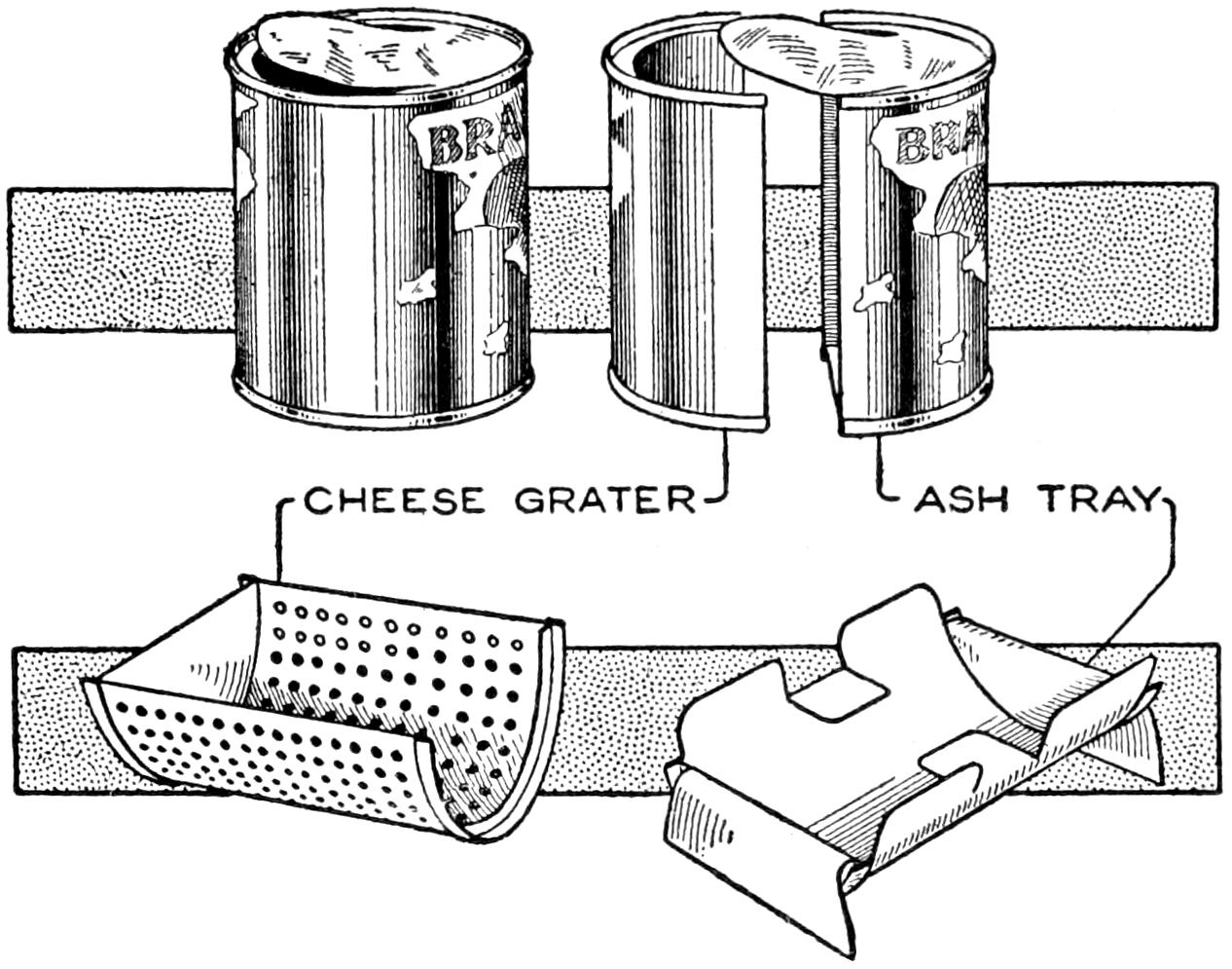
Necessity Resulted in the Making of a Cheese Grater and Ash Tray from a Tin Can
Being in need of a cheese grater and finding it inconvenient to go many miles to town, I constructed a satisfactory makeshift. I took a heavily tinned can and cut it in two, as shown in the sketch. By punching holes through it from the inside a practical grater resulted. From the remaining half of the can I made an ash tray, as shown at the right of the sketch. The semicircular ends were bent over to form a rest, and by cutting portions at the sides and bending them in, a convenient rest for a pipe or cigar was afforded.—Gus Hansen, Peachland, B. C., Canada.
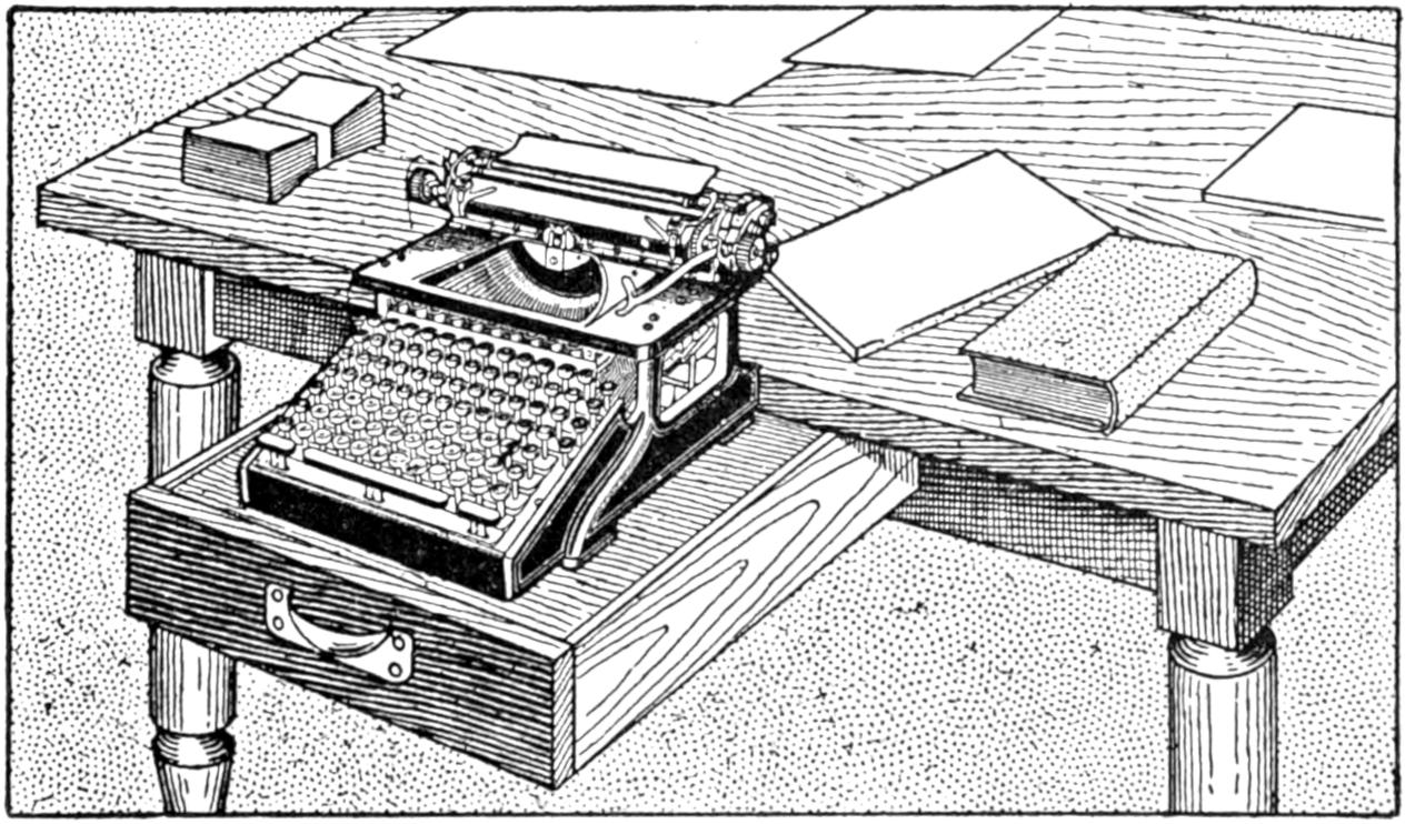
Remove the Drawer and Replace It Inverted, to Provide a Convenient Rest for the Typewriter
Travelers and others who carry typewriters on their journeys frequently find it inconvenient to use the tables provided because they are usually too high for typewriters. A method of overcoming this difficulty is to withdraw the drawer from the table and invert it in the slide as shown. The typewriter may then be placed upon the bottom of the drawer and will be considerably lower than if placed upon the table top.
[226]
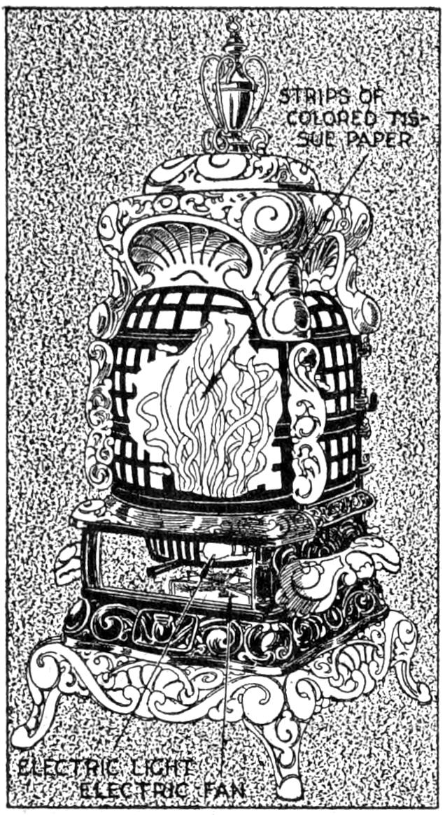
Window decorations may frequently be made attractive by the use of an imitation fire in a stove or a fireplace, when an indoor setting is on display. To produce such an effect, put an electric fan below the place at which the imitation fire is to be arranged and run an electric-light cord, with a red globe attached to it, to the center of the “flame.” Cut a number of strips of Indian red tissue paper and fix the lower ends of these to form a circular mass above the globe. When the light is turned on permit the fan to direct a stream of air against the tissue-paper ribbons, forcing them upward to appear like tongues of flame. The sketch shows this method applied to a heater. The fan is placed in the ash box and the electric light is conducted through the grate.
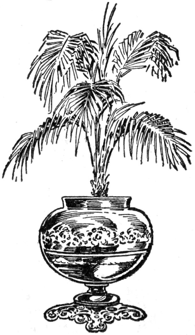
Some of the metal bodies of old lamps, and they are usually brass, are of such ample size and so neatly embossed that they can be readily used as jardinières instead of being handed to the junk man. It is only necessary to remove the lamp part, and set the plant pot into the bowl of the stand, as shown in the sketch.—H. N. Wolfe, Chicago, Ill.
A knob was broken from the lid of a coffeepot, which was valued by reason of its associations. Attempts to fasten the broken portions together were unsatisfactory, and the rough surface, where the earthenware was broken, was ground smooth and fitted with a carefully shaped wooden knob. A hole was drilled through the center of the lid with an old file and the wooden knob bolted into place. When stained appropriately, the repair was quite satisfactory.
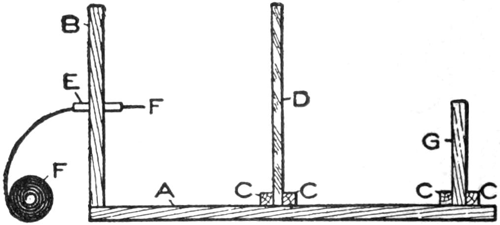
Length of Magnesium Ribbon Burned Determines the Time of Exposure
A convenient homemade printing device consists of a smooth board, A, 2 ft. long and 1 ft. wide, and an upright, B, which is 1 ft. square. Bore a hole in the center of the upright for the small tin holder E, to carry the magnesium ribbon, made by folding a piece of tin to fit it. Small pieces of wood, CC, are nailed across the board to hold the ground glass D and the printing frame G. The ground glass is 10 in. from the upright, and the printing frame is 10 in. from the ground glass. The latter is 1 ft. square and is used to diffuse the light from the magnesium ribbon F, which may be purchased from any dealer in photographic supplies. The length of exposure varies according to the length of ribbon which is permitted to burn. This should be tested out carefully before making exposures.—Gustave Straub, Albany, N. Y.
¶In sandpapering a varnished surface between coats, especial care should be taken to avoid rubbing through at sharp edges.
[227]

The labor of spading a garden of even moderate size is sufficient to warrant the person who undertakes the job in making a hand plow like that shown in the illustration, for it will serve many years, with reasonable care. I made one worth about $5 at an outlay of 25 cents, gathering the necessary wood and metal from among old machine parts and pick-up material.
An old wheelbarrow provided the 16-in. wheel. The handles were made from a ⁷⁄₈ by 4-in. strip of spruce, 5 ft. long. They were marked on the strip so that one of the curved grips was at each end, on opposite edges. The curved parts of the grips were cut with a keyhole saw, and when a kerf long enough to admit a large ripsaw was cut, the board was ripped into the two handles. They were smoothed and the grips trimmed with a sharp knife. A section of broomstick was cut for the upper brace. The lower one is made of a strip of iron, ¹⁄₄ by 1¹⁄₄ by 12 in., drilled for ¹⁄₄-in. bolts, and bent at right angles, 1¹⁄₂ in. from each end. Drill a ¹⁄₄-in. hole at the middle, to engage a bolt on which the vertical strip is supported, and adjusted to the operator, as shown in Fig. 1.
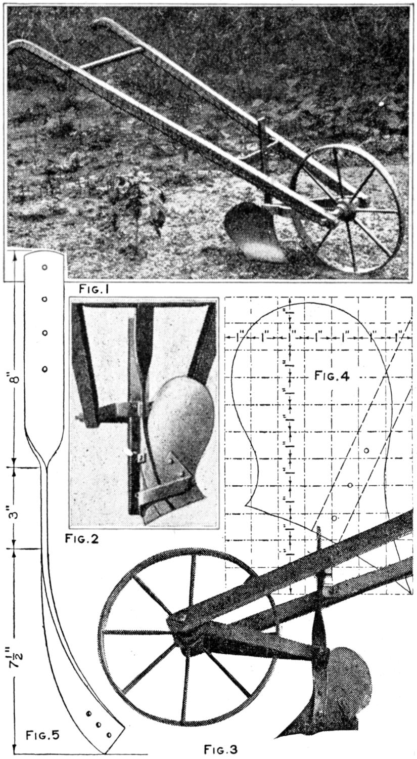
| Fig. 1 | |||
| Fig. 4 | |||
| Fig. 2 | |||
| Fig. 5 | Fig. 3 | ||
This Hand Garden Plow was Made of Old Material, a Shovel being Used for the Making of the Moldboard
Cut a strip, ¹⁄₄ by 1¹⁄₄ by 18 in., for the vertical support, shown in Fig. 5. Drill four ¹⁄₄-in. adjusting holes, 1 in. apart, at the upper end, and three ¹⁄₄-in. holes at the lower end for fastening the strip to the moldboard, as shown in Fig. 3. Drill a ⁵⁄₁₆-in. hole at the 7¹⁄₂-in. mark, for bolting the strip to the braces, the other ends of which are fitted on the ³⁄₈ by 10-in. bolt used as an axle. Cut the two braces 14 in. long, of ¹⁄₄ by 1¹⁄₄-in. strips, and drill a ³⁄₈-in. hole in the forward end of each, to fit the axle, and a ⁵⁄₁₆-in. hole in the opposite ends, 1 in. from the ends in each case. Cut a strip, ¹⁄₈ by ³⁄₄ by 12 in., for the landside, as shown in Fig. 2, bent under the moldboard, and bolted to it. The proper angle can best be bent after the moldboard is made and fitted.
[228]
The method of marking the shape of the moldboard on the blade of an old shovel is shown in Fig. 4. Make a pattern of cardboard, marking it into 1-in. squares. Draw the shape of the moldboard by tracing the outline through the corresponding squares, using the diagram as a guide. Mark the position of the bolt holes, for fastening it to the vertical support, indicated by the dash lines at the right. Cut out the pattern and trace around it on the shovel, using the thickest part for the point of the share. Cut out the outline, smooth the edges, and point up the cutting edge. Drill holes for fastening the moldboard to the vertical strap with ¹⁄₄-in. bolts, and for the fastenings to the landside, with ³⁄₁₆-in. bolts.
Curve the moldboard into shape and fit it to the various supports so that it sits properly, as shown in Fig. 1, seen from the furrow side, in Fig. 2, from the rear, and in Fig. 3, from the land side. Bend the 12-in. strip into shape, as shown in Fig. 3, and bolt it into place, to form the landside. Assemble the parts, being careful that the wheel and landside are set in line, as shown in Fig. 2, and that the rear edge of the latter is raised slightly, as in Fig. 3. The plow should be given a coat of paint, and the cutting parts made smooth, and oiled.
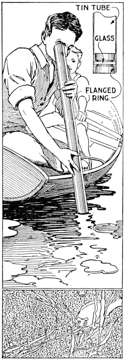
A water telescope is easy to make and will afford much pleasure in exploring plant or animal life in comparatively shallow water. The device is made by fitting a heavy glass disk into the end of a round metal tube, about 2 in. in diameter. The glass is fitted between two rings of metal, preferably with a small flange set against the glass. A waterproof cement is used to fix the glass between the rings. To use the “telescope,” rest it on the side of a boat or other convenient place at the water, and set the lower end, containing the glass, under the water. Remarkably clear views may be had in this way.—S. Leonard Bastin, Bournemouth, England.
Writing legibly on a fast-moving train is difficult to a person unaccustomed to it. The railroad conductor knows the trick of it and manages to get along quite satisfactorily. He prefers to write in a standing position and holds his right elbow firmly against his side. The reason for this is that in a sitting posture there is too much lateral movement in the trunk of the body, while in a standing position this is more easily controlled. When the arm swings freely, as in ordinary writing, several joints of the body are affected in the process, each of which is capable of its own motion. Holding the elbow against one’s ribs “breaks” these motion tendencies, except that of the wrist, which movement is necessary in writing, and thus the pencil, or pen, is more easily controlled.
The same principles modified apply in using a typewriter on a moving train. Many traveling men, news correspondents, and others, carry portable typewriters and do much of their writing while traveling on trains, not to mention the various railroad and government men who travel in office cars and necessarily must get out their correspondence en route. It is extremely difficult to execute neat typewriting on a moving train with free-arm movement, even though the central portion[229] of the car where the vibration and swing is less severe, is selected. As I am employed in such capacity, I had to evolve some plan to expedite the work. I am able to do typewriting quite rapidly by resting the palm of the hands, near the wrists, against the front edge of the typewriter frame surrounding the keyboard, and using the swing of the fingers instead of that of the whole arm, as in ordinary typewriting.—Victor Labadie. Dallas, Tex.
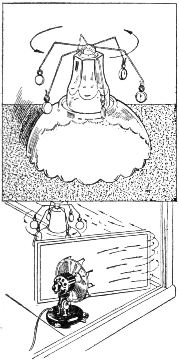
A jeweler attracted passers-by and not a few customers by placing a revolving display in his window which was kept in motion by means of the arrangement shown in the sketch. A 10-in. cut-glass bowl was placed, upside down, near the front of the show window. An inverted tumbler was set upon it and a small tin box was pivoted on the tumbler by means of a needle soldered inside of it. Six arms of wire were soldered to the box, and watches were suspended from them. The carefully balanced frame revolved easily on the point of the needle. It was kept in motion by the draft from a fan hidden behind a mirror.—H. S. Hart, Shreveport, La.
The cutting of a considerable area of sod is tedious work when done by hand, and it is difficult to make the sections of uniform thickness and size. These important features are provided for by the use of the homemade sod cutter shown in the sketch. To start a cut across a meadow or lot, a notch is cut in the turf for the blade, and the device is set into place, stamping it down to give a good start. The operator stands on the plank in front of the blade, and a little practice will soon determine the best position for ease in operation. When a cut has been completed, the cutter is dragged to a fresh starting place, the driver turning it over on the upper side. The strips are cut into suitable lengths and piled conveniently for removal with a stone boat or wagon.
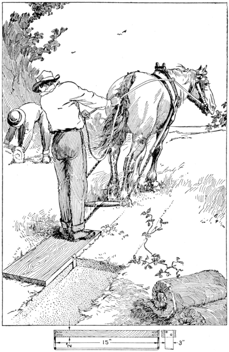
With This Device Sod may be Cut Quickly and of Uniform Width and Thickness
The device may be made of any suitable width; 15 in. between the inner edges of the blade, and the latter set to cut a depth of about 2¹⁄₂ in., being desirable. The board is a 2-in. plank, about 4 ft. long. The blade should be set with the cutting edge slanting slightly downward so as to make the device “bite” into the ground. A smaller cutter may be made for use by boys, several of whom may draw it.—F. H. Sweet, Waynesboro, Va.
[230]
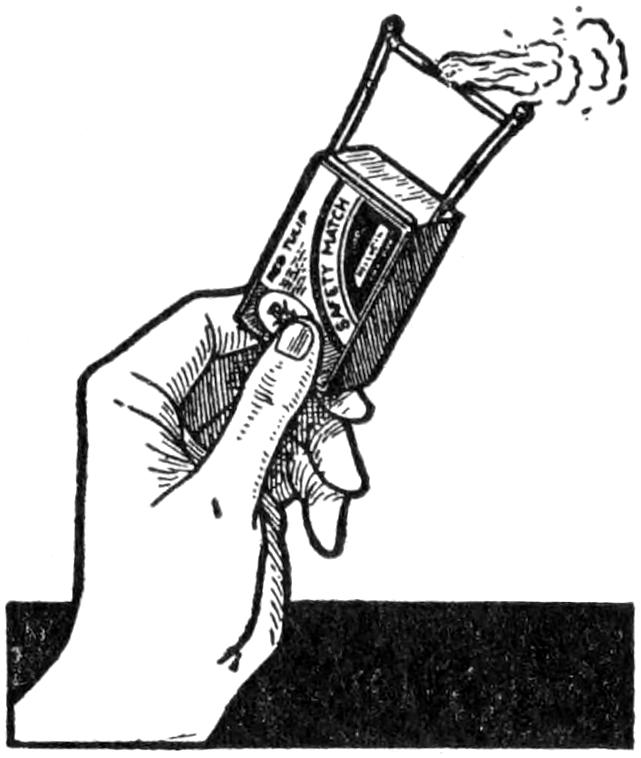
All that is required to perform this trick is a box of safety matches. Four matches are removed and three of them arranged as shown in the sketch. The performer then tells his friends that he will light the fourth match and set the cross match on fire in the center, then asks which match of the standing ones will light first. Most persons will not stop to think and guess either one or the other. As a matter of fact, after the cross match is set on fire it soon burns the wood away, and the pressure of the two side matches will cause it to spring out so that neither catches fire.—Contributed by Abner B. Shaw, North Dartmouth, Massachusetts.
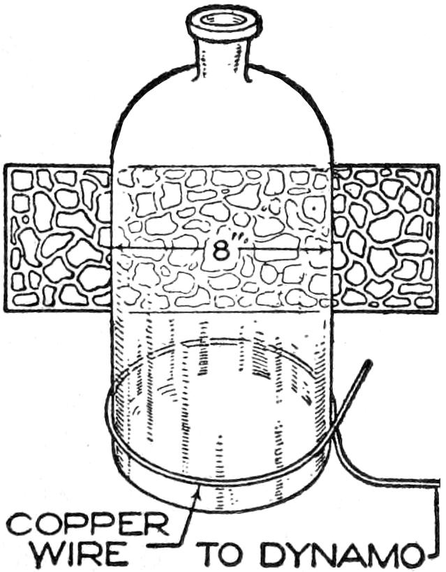
Performing an experiment in a laboratory, it became necessary to have some apparatus which we did not possess at the time. A bell jar could have been used, but this we did not have, and as a substitute we used a large glass bottle, 8 in. in diameter, with the bottom removed. In order to do this, we first made a mark around the outside of the bottle near the bottom with a glass cutter. A piece of copper wire, ¹⁄₃₂ in. in diameter, was then wound around the outside on the mark and connected to the circuit.
As the wire would expand enough to make it slip off the bottle when heated red-hot, pliers were used to keep it taut about the bottle when the current was turned on. A current of 110 volts and 5 amperes was run through the wire, heating it red-hot, and this cracked the glass exactly on the line marked by the glass cutter.—Contributed by R. E. Hollis, Chicago, Ill.
Muffin-pan trays used by the housewife in baking make serviceable containers for nails, screws, and other small articles used in a shop. The illustration shows the pans fitted into a box, and sliding in grooves cut into the sides with a saw.
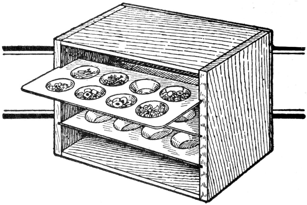
The Metal Trays Are Substantial and may be Removed Readily for Use Elsewhere
The box is made with the end pieces lapping over the top and the bottom this being a better construction to carry the weight of the trays. The wood used in the sides is ⁷⁄₈ in. thick, in order that a saw cut may be made to a depth of ¹⁄₄ in. without weakening the support. Thinner wood may be used if instead of saw cuts small strips of wood are nailed against the side on which the trays may slide.—Contributed by Harry J. Blacklidge, San Rafael, Cal.
Dipping ordinary parlor matches into melted paraffin and permitting them to dry thoroughly will enable them to withstand water. The paraffin acts like a wax candle and is unaffected by the moisture. This should be of aid to campers and others who find it hard to keep matches dry.—Contributed by T. W. Lambert, Jr., New York, N. Y.
[231]
Homemade Electric Locomotive Model
and Track System
By A. E. ANDREW
PART I—The Motor
The electric locomotive described may be constructed by boys having average mechanical ability and the necessary tools. However, in any piece of mechanical construction care must be taken to follow the instructions. The material required is inexpensive, and the pleasure derived from such a toy is well worth the time used in its construction.
The making of the outfit may be divided into three parts, the first of which is the motor; second, the truck which is to carry the motor and the body of the car, and third, the track system upon which the engine is to operate. A side view of the locomotive is shown in Fig. 1.
The motor is of the series type, having its field and armature terminals connected to the source of electrical energy through a special reversing switch. By this means the rotation of the armature may be reversed to make the locomotive travel forward or backward. The armature and field are constructed of sheet-iron stampings, riveted together.
The detailed construction of the armature and its dimensions are shown in Fig. 2. The shaft upon which the armature core and commutator are to be rigidly mounted is made of a piece of steel rod, ⁷⁄₃₂ in. in diameter. A portion of this rod, 2¹⁄₄ in. long, is threaded with a fine thread, and two small brass, or iron, nuts are provided to fit it. The ends of the rod are turned down to a diameter of ¹⁄₈ in. for a distance of ¹⁄₈ in. These are to fit in the bearings that are to be made later.
Cut from thin sheet iron a sufficient number of disks, 1¹⁄₈ in. in diameter, to make a pile exactly ⁵⁄₈ in. thick when they are securely clamped together. Drill a hole in the center of each of these disks, of such a size that they will slip on the shaft snugly. Remove the rough edges from the disks and see that they are flat. Cut two disks of the same size, from a piece of ¹⁄₁₆-in spring brass, and drill a hole in the center of each, so that they will slip on the shaft. Place all these disks on the shaft, with the brass ones on the outside, and draw them up tightly with the nuts provided. Be sure to get the laminated core in the proper position on the shaft by observing the dimensions given in the illustration, Fig. 2.
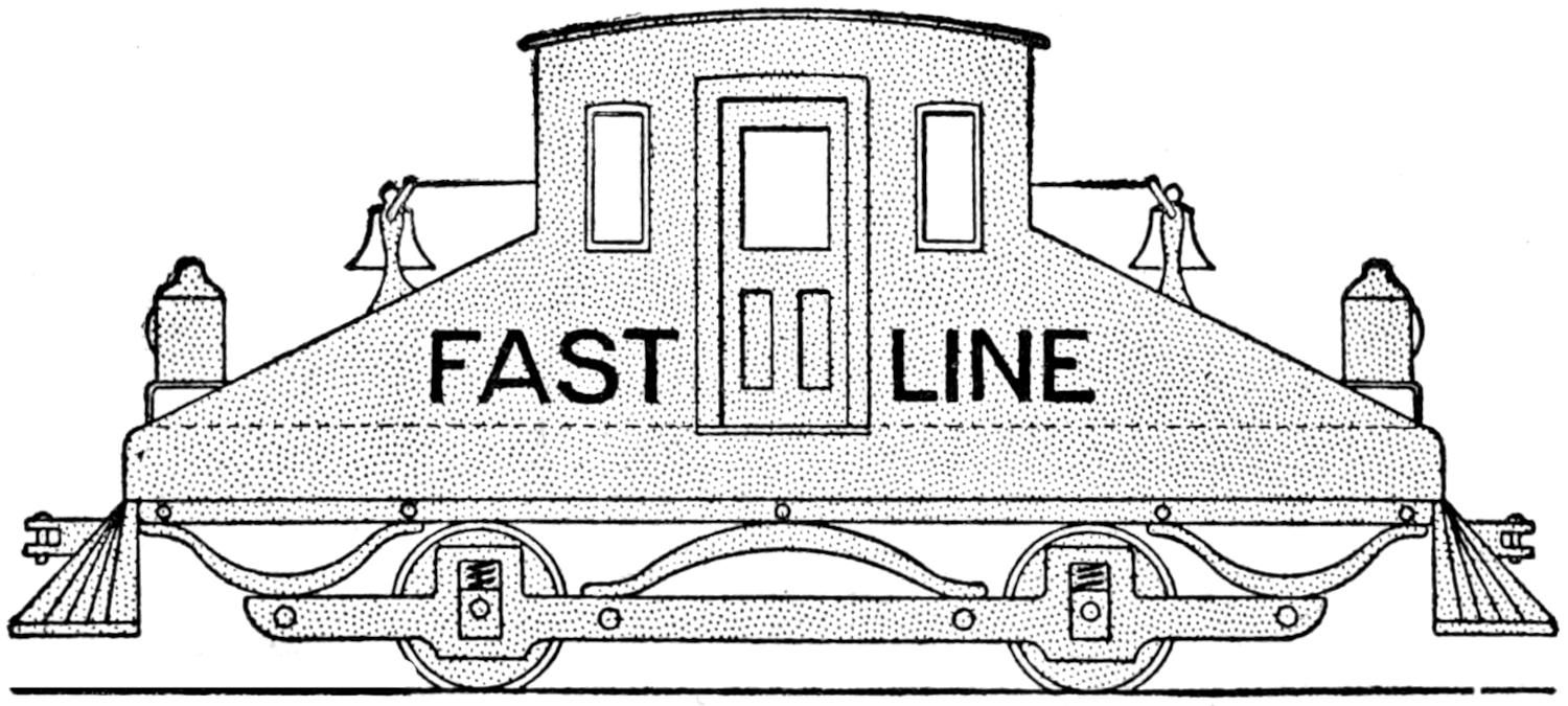
Fig. 1
Side View of a Locomotive Designed to be Operated
with Either End Forward
After the disks have been fastened, clamp the shaft in the chuck of a lathe and turn down the edges of all the disks so that they form a smooth[232] cylinder, 1¹⁄₁₆ in. in diameter. Draw a circle on the side of one of the brass disks, ³⁄₃₂ in. from the edge, while the shaft is held in the chuck. Divide this circle into eight equal parts and make a center-punch mark at each division. Drill eight holes through the core lengthwise with a ³⁄₁₆-in. drill. If the centers of the holes have been properly located, all the metal on the outside will be cut away, as shown in the end view, at the right in Fig. 2. The width of the gaps, F, G, H, etc., thus formed, should be about ¹⁄₁₆ in. Smooth off all the edges with a fine file after the holes are drilled.
A cross-sectional view of the commutator is shown at the extreme left, Fig. 2. It is constructed as follows: Take a rod of copper or brass, ⁷⁄₈ in. diameter, and 1¹⁄₄ in. long; clamp one end in the chuck of a lathe. Turn the other end down to a diameter of ³⁄₄ in., and drill a ¹⁄₂-in. hole through it at the center. Cut away the metal from the end to form a disklike recess.
Cut off a disk, ⁵⁄₁₆ in. thick, measuring from the finished end, from the piece of stock. Place this disk in a chuck, with the unfinished end exposed, and cut away the metal in a dish form, as shown at B. Cut small slots, into which the ends of the wires used in winding are to be soldered, as shown at 1, 2, 3, etc., in the right-hand view of Fig. 2. Obtain two brass nuts, about ¹⁄₄ in. in thickness, and turn their edges down so that they correspond in form to those shown at C and D. Divide the disk ring, just made, into eight equal parts, by lines drawn across it through the center. Cut eight slots at these points, in the rim of the disk. These cuts should be through the rim. Fill each of the slots with a piece of mica insulation.

Fig. 2
Fig. 3
How the Armature Core is Made of Soft-Iron Disks for the Lamination, at the Left. Diagram for the Winding of the Armature Coils and Their Connection to the Commutator, at the Right
Place one of the nuts on the shaft and then a washer of mica insulation shown by the heavy lines, near A and B; then the ring, a second piece of mica, and last the nut, C. The latter should be drawn up tightly, so that the insulation in the slots in the disk are opposite the drilled slots in the armature core, as shown in the right-hand view of Fig. 2. After the disk has been fastened securely, test it to learn whether it is insulated from the shaft. This is done by means of a battery and bell, connected in series, one terminal of the circuit being connected to the disk, and the other to the shaft. If the bell rings when these connections are made, the ring and shaft are not insulated. The disk must then be remounted, using new washers of mica insulation. Mica is used because of its ability to withstand a higher degree of heat than most other forms of insulation.
Each of the eight segments of the dished disk should be insulated from the others. Make a test to see if the adjacent commutator segments are insulated from each other, and also from the shaft. If the test indicates that any segment is electrically connected to another, or to the shaft, the commutator must be dismantled, and the trouble corrected.
The armature is now ready to be wound. Procure ¹⁄₈ lb. of No. 26 gauge insulated copper wire. Insulate the shaft, at E, with several turns of thin[233] cloth insulation, and also insulate similarly the nuts holding the armature core and the inside nut holding the commutator. Cut several pieces from the cloth insulation, wide enough to cover the walls of the slots in the core, and long enough to extend at least ¹⁄₁₆ in. beyond the core at the ends. Insulate slots F and G thus, and wind 15 turns of the wire around the core lengthwise, passing the wire back through the slot F, across the back end of the core, then toward the front end through slot G, and back through F, and so on. About 2 in. of free wire should be provided at each end of the coils.
In passing across the ends of the armature, all the turns are placed on one side of the shaft, and so as to pass on the left side, the armature being viewed from the commutator end. The second coil, which is wound in the same grooves, is then passed on the right side, the third on the left, and so on. After this coil is completed test it to see if it is connected to the armature core. If such a condition is found, the coil must be rewound. If the insulation is good, wind the second coil, which is wound in the same slots, F and G, and composed of the same number of turns. Insulate the slots H and J, and wind two coils of 15 turns each in them, observing the same precautions as with the first two coils. The fifth and sixth coils are placed in slots K and L, and the seventh and eighth, in slots M and N.
The arrangement of the half coils, slots, and commutator segments is given in detail in Fig. 3. Each coil is reduced to one turn in the illustration, in order to simplify it. From an inspection of this diagram it may be seen that the outside end of the second coil in the upper row of figures, at the left end, is connected to the inside end of the fourth coil at segment 1, in the lower row of figures, representing the segments of the commutator. The outside end of the fourth coil is connected with the inside end of the sixth coil, at segment 2; the outside end of the sixth coil is connected with the inside end of the eighth coil at segment 3; the outside end of the eighth coil is connected to the inside end of the coil 1 at segment 4; the outside end of the coil 1 is connected to the inside end of the coil 3 at segment 5; the outside end of the third coil is connected to the inside end of the fifth coil at segment 6; the outside end of the fifth coil is connected to the inside end of the seventh coil at segment 7; the outside end of the seventh coil is connected to the inside end of the second coil at segment 8, and the outside end of the second coil is connected to segment 1. completing the circuit.
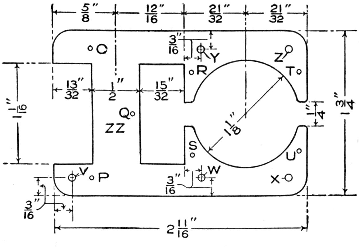
Fig. 4
Pattern for the Field Stampings, Several Pieces being
Used to make the Desired Thickness
In winding the coils on the core, their ends should be terminated close to the commutator segments to which they are to be connected, in order to simplify the end connections. After all the coils are wound and properly tested, their ends may be connected as indicated. They are then soldered into the slots in the ends of the commutator segments. The completed winding is given a coating of shellac.
The dimensions and form of the field stampings are given in Fig. 4. A number of these cut from thin sheet iron to make a pile ⁵⁄₈ in. thick when clamped together is needed. The dimensions of the opening to carry the armature should be a little less than that indicated in the sketch, as it will be necessary to true it up after the stampings are fastened together. Use one of the stampings as a pattern, and drill seven small holes in each, as indicated by the[234] letters O, P, Q, R, S, T, and U. Fasten them together with small rivets, and true up the opening for the armature to a diameter of 1¹⁄₈ in. Drill five ¹⁄₈-in. holes, as indicated by the letters V, W, X, Y, and Z, to be used in mounting the pieces, which are to form the armature bearings, brush supports, and base of the motor.
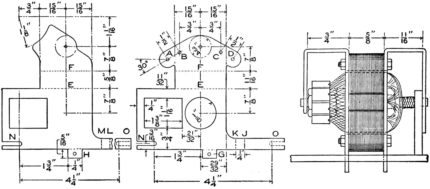
Fig. 5
Fig. 6
Detail of the Field-Structure Supports, One Being for the Left Side and the Other for the Right. The Supports are Shown in the Place at the Right
Cut two rectangular washers from a piece of thin fiber insulation, with outside dimensions of 1¹⁄₈ in. and 1¹⁄₄ in., and an inside opening, ¹⁄₂ in. by ⁵⁄₈ in. Cut open these washers and slip them in position on the portion of the field marked ZZ. Wrap two turns of the cloth insulation about this part, which is to form the field core, and wind the space full of No. 18 gauge enamel-insulated copper wire. Give the completed winding a coat of shellac. The terminals of this winding should be brought out through two holes drilled in one of the fiber washers, one near the core and the other near the outer edge. It is better to have the field terminals at the lower end of the part ZZ than at the upper end.

Fig. 7
Detail of the Brush Holders, One Inch Long, with
Holes as Shown
Now cut two pieces from ¹⁄₁₆-in. sheet brass, similar to those shown in Fig. 5. Place them on opposite sides of the laminated field structure, shown in Fig. 4, and carefully mark the position of the holes, V, W, X, Y, and Z, as indicated in Fig. 4, and drill ¹⁄₈-in. holes, where the marks were made. Lay out and drill ¹⁄₈-in. holes, A, B, C, and D, Fig. 5. Bend the upper portion of the pieces at right angles to the lower portion, along the dotted lines E, and then bend the end of the horizontal portions down along the dotted lines F, until they are parallel with the main vertical parts of the pieces. The latter should be bent so that one forms the left support and the other the right, as shown in Fig. 6.
Bend the projections G and H at right angles to the vertical main parts. The parts at the bottom are bent, one back along the dotted line J and forward on the line K; the other forward on the line L and back on the line M. The pieces are then mounted, on the side of the field structure, as shown in Fig. 6. The supports are fastened in place with five small bolts. The grooves N and O, in Fig. 5, are used in mounting the motor on the axles of the truck. They will not be cut until after the truck is constructed.
The brush holders are made of two pieces of hexagonal brass, each 1 in. in[235] length, having a ¹⁄₈-in. hole drilled in the end to a depth of ⁷⁄₈ in., and a threaded hole in the other end, for a small machine screw, as shown in Fig. 7. Two holes are drilled and threaded in one side of each of these pieces. These holders are to be mounted, by means of screws, through the holes A, B, C, and D, Fig. 5. Each holder must be insulated from its support. The distance of the holder from its support should be such that the opening in its end is in the center of the commutator. The brushes are made of very fine copper gauze, rolled to form a rod. They are made long enough to extend about ¹⁄₂ in. into the holder, when they are resting on the commutator. A small spiral spring is placed in the holder, back of the end of the brush, and which will serve to keep the latter in contact with the commutator.
Temporary connections are made and the motor is tested with a six-volt battery. The construction of the motor may be modified as to the length of shaft, and other minor details, and may be used for other purposes by fitting it with pulleys, a countershaft, or other transmission devices.
String solder of a size convenient for electrical work, or other soldering, where only a small quantity is desired, may be made by adapting a ladle for the purpose. Drill a small hole through the ladle near its upper edge. Melt the solder and pour it through the small hole, permitting it to fall on a slab of marble, slate, or stone. The ladle must be moved in zigzag lines in order to prevent the string from crossing and to make it possible to roll up the solder into rings of a convenient size.—Contributed by L. E. Fetter, Portsmouth, N. H.
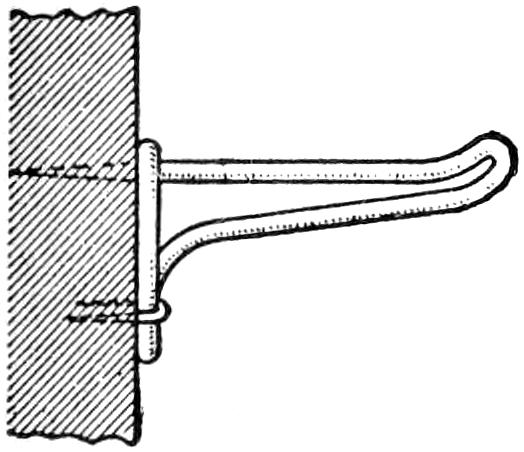
A good way to keep a common wire coat hook in an upright position is to drive a small wire staple over the smaller hook. In public places, such as halls, this will often prevent their removal and save considerable annoyance.—Contributed by Harry L. Dixson, Chicago, Ill.
¶The second coat of varnish should never be put on until the first has been “mossed” (rubbed) off; as, otherwise, it will not stick well.
To build a small cement grotto for an aquarium, make a clay mold by roughly excavating two right-angled gutters in a lump of clay. Grease, or shellac, the mold after it is dry. Apply cement of about the consistency of putty, or dough, filling the gutters roughly so as to give a rocklike finish. Small shells can be stuck into the cement while it is yet moist. Before entirely shaping the cement, a piece of heavy wire is bent to conform to the shape of the grotto and set in for a reinforcement.
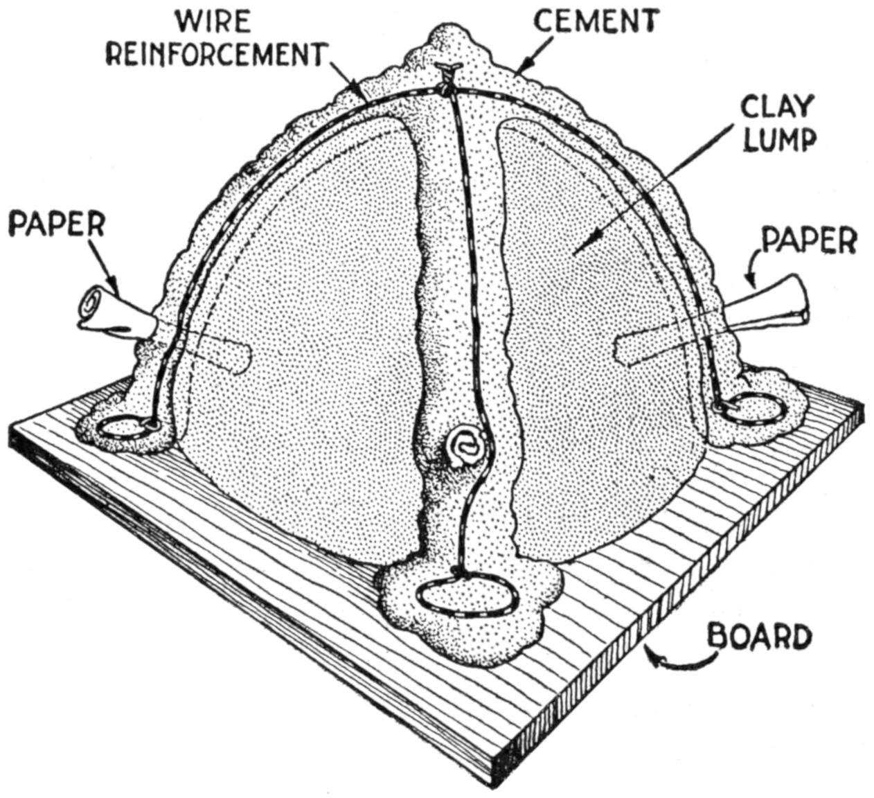
Cement Grotto Roughly Molded over Clay, Shaped to Make the Right Form
Holes can be made by twisting paper, so that it will extend out at each side, and laying cement over it. After the cement is thoroughly dry, the paper can be removed in sections.
[236]
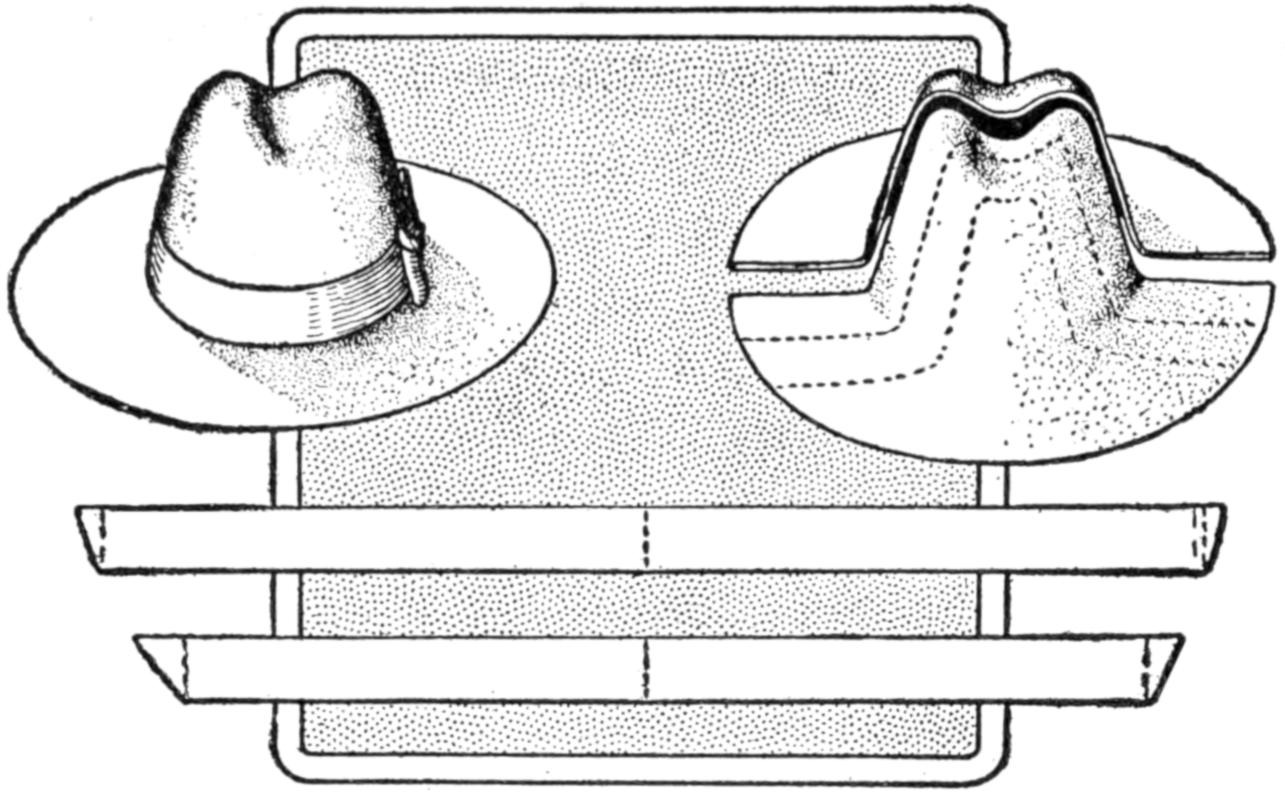
Cut the Hat into Halves and Then Cut It into Strips, from Which the Wicks are Made
Lamp wicks may be made cheaply at home from an old soft-felt hat. The hat should first be brushed clean and the brim flattened by ironing it. The greatest number of wicks may be obtained if the hat is cut into halves with a pair of scissors, and then cut into strips of the required size, as shown in the sketch. Soak the strips in vinegar for two hours, dry them out of doors, if convenient, and they are ready for use.—Contributed by George H. Holden.
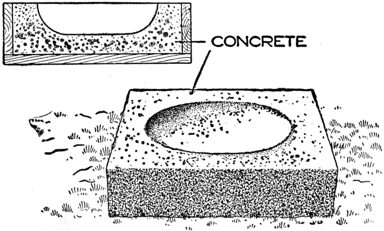
An Ordinary Washbasin was Used to Shape the Depression in the Concrete
A concrete worker was asked by a farmer to build a concrete basin for watering the poultry. Having no forms at hand, the mechanic used an ordinary washbasin and a wood box as shown in the illustration. The basin was greased before it was placed in the concrete. The completed concrete basin was buried with its upper surface level with the ground.—Contributed by James M. Kane, Doylestown, Pa.
The ground glass in my camera was broken while arranging to take a picture of a party one evening, and being unable to obtain another, I substituted a piece of white tissue paper drawn over a piece of plain glass. It did the work so well on that occasion that I have used it continuously since, and have found it better than the ground glass. It produces superior definition in the views on the glass, especially when working in a poor light, and in a good focusing screen.—Contributed by C. W. Smalley, Des Moines, Ia.
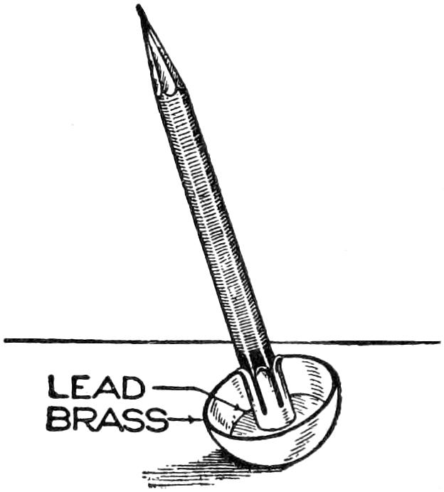
Mechanics, and others who have occasion to use a pencil on a workbench will appreciate the pencil holder shown in the sketch. It was made by soldering the small brass ferrule into the bottom of a portion of a brass knob, and weighting the knob with lead. The pencil will be held in an upright position where it may be easily seen.—Contributed by R. F. Hoffman, Chicago.
Incandescent electric bulbs that have been burned out may be repaired by shaking them, in order to cause the broken ends of the metal filament to strike together. By examining the broken filament one can determine in what direction to shake the globe. The sudden passage of the current upon contact causes an arc at the broken ends of the filament, welding them. A globe thus repaired should be placed in a socket where it will not be given undue disturbance and will then last for a considerable period.
[237]
Homemade Electric Locomotive Model
and Track System
By A. E. ANDREW
PART II—Construction of the
Locomotive Truck and Cab
Successful operation and construction that is feasible, yet of a reasonable standard of workmanship, are the essentials of the locomotive truck and cab described as the second feature of the locomotive and track system under consideration. The materials suggested are those found to be satisfactory, but substitutes may be used if caution is observed. The completed locomotive is shown in Figs. 1 and 2. The outward aspect only is presented, and, for the sake of clearness, the portions of the motor and driving rigging attached to it, that project below the cab, are omitted, These parts are shown assembled in Fig. 12, and in detail in the succeeding sketches.
The locomotive, apart from the motor, consists of two main portions, the truck and the cab. Consideration will be given first to the building of the truck and the fitting of the motor into it. The mechanical and operative features are to be completed before beginning work on the cab, which is merely a hood fixed into place with screws, set into the wooden cab base.
Begin the construction with the wheels, shown in Fig. 3. Make the axles of ¹⁄₈-in. round steel rod, cut 3³⁄₁₆ in. long.
Turn four wheels of ³⁄₈-in. brass. Drill a ¹⁄₈-in. hole in two of them so that they may be forced on the slightly tapered ends of the axle. Drill a ¹⁄₄-in. hole in each of the other wheels, and solder a collar, A, Fig. 3, on the inside surfaces of them. Two fiber bushings, B, should be provided to fit in the ¹⁄₄-in. openings in the wheels and to fit tightly on the ends of the axles. This insulates the wheels on one side of the truck from those on the other. If the rails forming the track are insulated from each other, the current supplied to the motor may pass in on one rail to the two insulated wheels, then to a brush, which bears on the brass collar A, through the windings of the motor, through the reversing switch to the other set of wheels, and back to the source of energy over the other rail, as shown in Fig. 15.
The wheels of the truck should fit on the axles tightly, since no means other than the friction will be employed in holding them in position. If the ends of the axles are tapered slightly, the wheels may be forced into place and will stay firmly. Do not force them on until the truck is finally assembled.
The truck frame should be constructed next, and its details are shown in Figs. 4 and 5. Make two sidepieces of ¹⁄₁₆-in. brass, 9³⁄₄ in. long and 1⁵⁄₈ in. wide, cutting out portions, as shown, in order to reduce the weight. This also gives the appearance of leaf springs.
The two rectangular openings are to accommodate the axle bearings. They should be cut to precise dimensions, and their edges should be squared off. Extensions, ¹⁄₁₆ in. wide, are provided at the middle of the upper edges of each of these openings. They are to hold the upper end of the coil springs,[238] which are to rest in the holes cut into the bearings, as shown at G, Fig. 7, and also in assembled form, Fig. 6.
Next drill four ¹⁄₈-in. holes in each of the sidepieces, as indicated at the letters H₁ to H₄, Fig. 5. For the cross supports use four pieces of brass rod, ¹⁄₄ in. square, and square off the ends to a length of 2³⁄₄ in. Drill holes in the center of the ends and tap them for ¹⁄₈-in. machine screws. Join the side and crosspieces as shown in Fig. 4. Two fiber washers about ¹⁄₁₆ in. thick should be placed on each axle at E and F, to hold the wheels from contact with the sidepieces.
Details of a bearing for the axles are shown in Fig. 7. The hole G carries the lower end of the coil spring, and the hole J is the bearing socket for the axle. Four spiral springs, having an outside diameter of ¹⁄₈ in. and a length of ¹⁄₂ in. when extended, should be provided. The extensions on the sides of the bearings fit against the inner faces of the sides of the truck. They hold the bearings in position and prevent them from falling out.
The base of the cab is made of wood, dimensioned as in Fig. 10. The center of the piece is cut away so as to provide a space for the motor, which extends above the upper edge of the truck, as shown in Fig. 12. This block is fastened in place by four screws through the upper crosspieces at the ends of the truck. The base should be made and fitted into place temporarily so as to be available in observing how the motor and its fittings are placed in relation to it. For convenience in assembling the parts of the truck and setting the motor, it may be removed readily.
Assembling the truck, including the motor, probably requires the most painstaking effort of any part of the construction of the locomotive. Too great care cannot be taken with it, as the dimensions are carefully worked out and failure to observe them may cause errors sufficient to make the locomotive unserviceable. Before undertaking this work it would be well to examine carefully the arrangement of the parts as shown in Fig. 12. The upper view shows the relation of the driving gears in mesh, and the lower view shows the machinery of the truck as seen from above.
The power from the motor is transmitted to one set of wheels by means of a small gear on the armature shaft engaging an intermediate gear, which in turn engages a large gear attached to the inside of one of the truck wheels. The center of the armature shaft is 1⁵⁄₁₆ in. from the center of the power axle, when both axles are in the slots provided in the motor frame, Fig. 12. The gears for the transmission may now be selected. The gear on the armature shaft should be as small, and that on the axle as large, as practicable. The intermediate gear should be of such a size that it will close the space between the small gear on the armature shaft and the large one on the axle. Gears suitable for the transmission may be purchased at a clock store for a small sum. If gears of exactly the proper size cannot be obtained readily, the position of the intermediate gear may be adjusted to produce a proper meshing of the gears.
Mount the small gear on the end of the armature shaft away from the commutator, so that there will be about ¹⁄₁₆-in. clearance between the outside surface and the shoulder at the end of the shaft. Fit it on tightly so that no other means of fastening will be necessary. Mount the large gear on the inside surface of one of the truck wheels, as shown in Figs. 3 and 12. Place the axle of the truck into the proper grooves in the motor frame, and mark the position of the center of the intermediate gear, when it engages the other gear. Drill a hole in the extension on the motor frame, provided as a support, to fit a small bolt with which the intermediate gear is fastened.
Place a washer between the gear and the piece upon which it is mounted, and a locknut on the threaded end of the bolt, drawing it up so that the gear has only sufficient play.
[239]
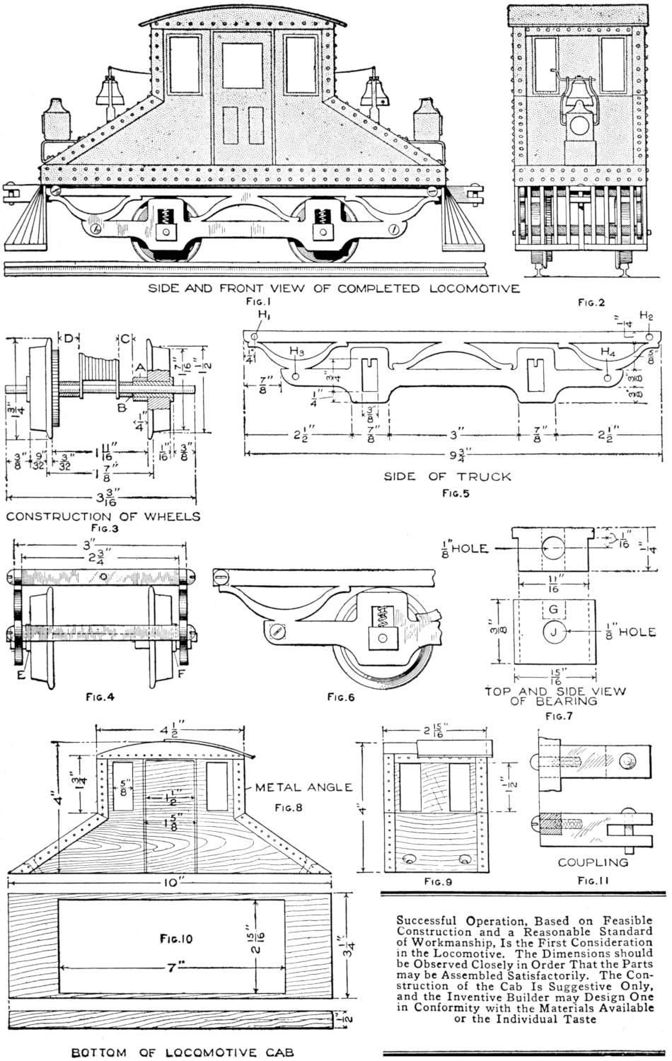
SIDE AND FRONT VIEW OF COMPLETED LOCOMOTIVE
Fig. 1
Fig. 2
CONSTRUCTION OF WHEELS
Fig. 3
SIDE OF TRUCK
Fig. 5
Fig. 4
Fig. 6
TOP AND SIDE VIEW
OF BEARING
Fig. 7
Fig. 8
Fig. 9
Fig. 11
Fig. 10
BOTTOM OF LOCOMOTIVE CAB
Successful Operation Based on Feasible Construction and a Reasonable Standard of Workmanship, Is the First Consideration in the Locomotive. The Dimensions should be Observed Closely in Order That the Parts may be Assembled Satisfactorily. The Construction of the Cab is Suggestive Only, and the Inventive Builder may Design One in Conformity with the Material Available or the Individual Taste
[240]
The slots in the motor frame to fit the free axle may now be cut, as shown in Fig. 12. Place the motor in position on the axle so that the gears all mesh properly. Fit tubes of insulating material with an outside diameter of ³⁄₈ in. at C and D, Fig. 3, and as also shown in Fig. 12. Insulation tubes should be provided for the second axle so as to hold the motor in position, and to keep the wheels in line. In mounting the various parts sufficient play should be allowed to prevent excessive friction.
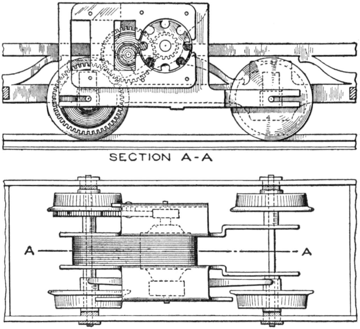
Fig. 12, Installation of the Motor, Showing Gears and Switch Contact Spring
The reversing switch, which is to be mounted on the under side of the motor frame, is shown in Figs. 13 and 14. It is provided with a control lever which projects out from under the truck frame. A small movement of the lever will produce the necessary changes in the connections. The operation of the switch may be understood readily from the diagram shown in Fig. 15. The moving element of the switch carries two pieces of copper, E and F, which connect the four stationary pieces of copper, A, B, C, and D, when the lever attached to E and F is moved to either side of its central position. The pieces of copper which are moved—E and F—are shown outside of the stationary pieces in Fig. 15 for purposes of a diagram only, and are actually directly over the ring formed by the stationary pieces.
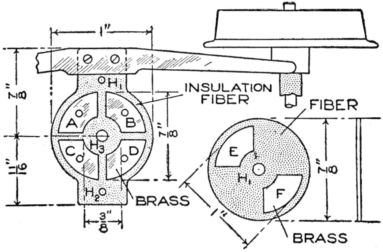
Fig. 13, Details of the Switch, Shaded Portions Being of Fiber Insulation
The operation of the switch is as follows: Assuming that the current enters at the terminal marked 1 and leaves at the terminal marked 2, then the direction of the current in the armature and series field will be as indicated in the diagrams. The direction of the current in the series-field winding is different in the two cases, which will result in opposite rotation of the armature.
The base of the switch is made of ¹⁄₁₆-in. fiber insulation; its dimensions are shown in Fig. 13. It is to be mounted on the two pieces projecting outward on the under side of the motor frame, as shown in Fig. 14. Drill a small hole in each of these projections, as indicated by the letters H₁ and H₂, and tap them to take a small machine screw. Next drill two holes, H₁ and H₂, Fig. 13, in the piece of insulation, with centers the same distance apart as those drilled in the projections. One end of this piece of insulation is extended to form a mounting for a thin brass spring, the ends of which bear on the brass collars insulated from the axles, as shown in Figs. 12 and 13. The form of this spring and the method of mounting it are also shown in Fig. 13.
The sections which come into contact in the switch are made as follows: Mount four pieces of thin copper or brass on the fiber base with rivets having their heads countersunk. Cut a disk, 1 in. in diameter, from a piece of sheet insulation and drill a hole H, in the center of it. Also drill a similar hole H₃ in the center of the switch base. Mount two pieces of copper or[241] brass, E and F, on the under side of this disk. The edges and ends of all six pieces of metal should be rounded off so that the pieces E and F will move freely over those on the base. The disk, or upper part of the switch, may be attached to the base by means of a small bolt placed through the holes at the center. A small spiral spring should be placed between the disk and the lower end of this bolt so as to keep the pieces of metal on the disk in contact with those on the base. Attach a small handle to the disk so that it will extend out on one side of the truck. Fix the switch into place by bolts through the holes H₁ and H₂, Fig. 14, on the bottom of the motor frame. The electrical connections should be made as shown in Fig. 15.
The detail of the couplers is shown in Fig. 11. They are made of brass, fitted to the upper crosspieces and fixed to them by machine screws. “Cowcatchers” may be made for the ends of the locomotive. Sheet metal, corrugated appropriately and bent to the proper shape, will afford the easiest method of making them. Those shown in Figs. 1 and 2 are made of strips soldered together, and also to the upper crosspieces; they are strengthened by a cross strip at the bottom, opposite the point.
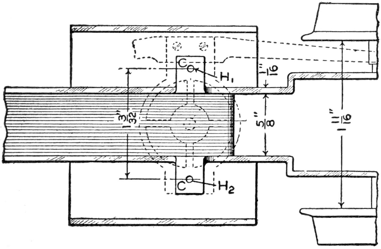
Fig. 14, View of the Under Side of the Motor, Showing How Switch is Fixed into Place
The cab is to be made apart from the truck and is to fit upon the base, as shown in Figs. 1 and 2. It is fixed into place by four screws and can be removed easily for examination of the locomotive mechanism. The dimensions for the cab are shown in Figs. 8 and 9, and may be varied by the builder.
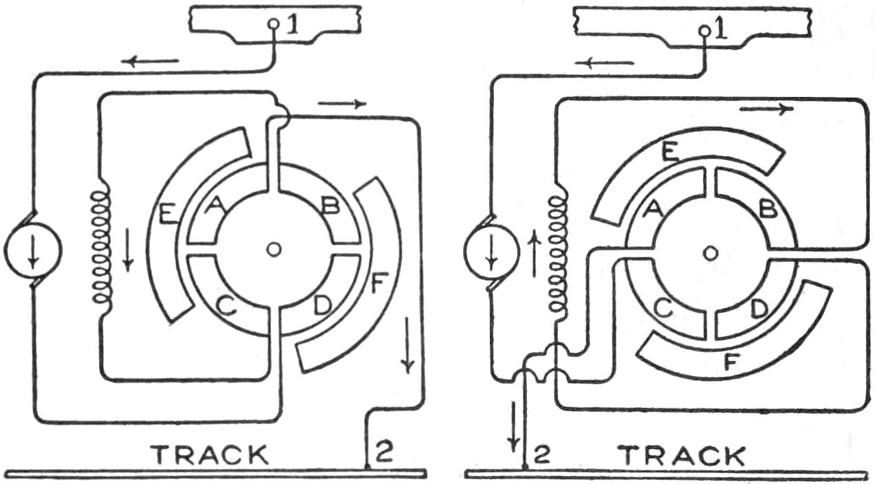
Fig. 15, Diagrams of the Reversing of Motor by Shifting Switch to Form Contact Between Pairs of Brass Sectors Set in the Fiber Switch Base
Sheet metal or wood may be used in the construction, and the joints soldered on the inside or riveted, as shown in the illustration. The window and door openings may be cut out or painted on. Small bells may be mounted on the ends of the cab, adding to its appearance. The headlights shown in Figs. 1 and 2 may be cut from wood or made of sheet metal. Light bulbs may be installed, and their voltage should correspond to that of the motive energy. The terminals for the sockets of the headlight lamps should be connected to the frame of the truck and to the spring, which bears upon the brass collars on the wheels, which are insulated from the axles, as shown at A, Fig. 3.
This completes the locomotive in all essential details and it is ready to be placed upon the track to be tested. The track system will be considered in a subsequent article.
When flour paste becomes watery upon cooling, it is evidence that the mixture has been boiled too long. Only the best flour should be used for making paste. Many paper hangers do not boil paste. They make a stiff batter with lukewarm water, stirring out all lumps, and then briskly stir in boiling water. When the mass thickens continue stirring, but add no more hot water. Pour a little cold water on top and set the paste away to cool.—Contributed by A. A. Kelly, Malvern, Pa.
[242]
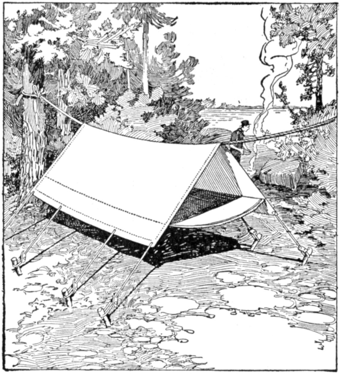
A Comfortable Sleeping Tent is Provided by the Arrangement Shown in the Sketch
Compactness in transportation and general serviceableness are features of the hammock tent shown in the illustration. It is made by sewing a piece of canvas to the sides of an ordinary “dog” or shelter tent and may be made of a piece of canvas or tarpaulin. The tent is suspended by the ridge from a heavy rope supported on trees or posts. It is kept taut on the sides by tent ropes attached to stakes driven in the ground. This form of tent is particularly convenient in providing a good sleeping place in very small space. It is free from dampness, and the camper is provided with a comfortable rest free from prowling animals, without the use of a cot.—Daniel C. Duvall, Washington, D. C.
A garden spade, or fork, broken at the handle may be repaired by joining the broken ends with a piece of old iron water pipe. The broken ends should be trimmed carefully and driven into the piece of pipe. In order to make a more secure joint, holes may be bored and countersunk at each end of the pipe and screws fixed into them. If the break is so close to the handle that the latter is useless, a new one may be made by fixing a pipe tee, with a wooden rod as a handle, to the end of the fork or spade.—George H. Holden, Chesterfield, England.
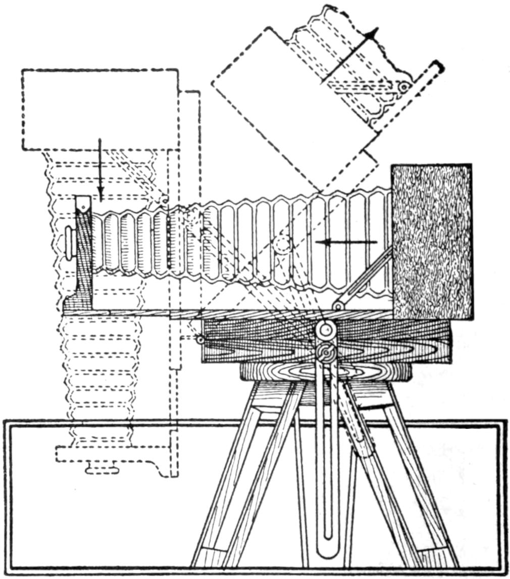
The Homemade Tilting Top Is Convenient in Making Photographs at a Variety of Angles
Pointing a camera up, or down, as in photographing tall buildings with the ordinary camera tripod, is awkward and requires much time to make a satisfactory adjustment. To overcome this, a tilting top was made for the tripod, as shown in the illustration. The extra top consists of two boards hinged at one end. The lower board has a tripod socket to fit the tripod, while the upper one has a tripod screw for fastening the camera. Two metal brackets are provided, having slots through which binding screws are fitted, and clamped with wing nuts. This permits the camera to be tilted at various angles, or reversed for vertical pictures, without removing it from the tripod. Several positions are suggested and a little experimentation will give numerous other possible uses. Devices of this character may be purchased, but the one shown is easily made and serves its purpose well.—R. C. Miller, Pittsburgh, Pa.
[243]
Homemade Electric Locomotive Model
and Track System
By A. E. ANDREW
PART III—Construction of the Track
System
Operation of the electric-locomotive model described in the previous articles is feasible only with a properly constructed track system. This equipment, including curves and switches, is to be described in this, the final, article. Two functions are to be performed by the track system: It must serve as a support and guide for the locomotive and provide a path over which the current from the source of energy is supplied to the motor within the locomotive and returned to the source. On this basis, then, the construction may be divided into two parts: the mechanical and the electrical features. If the mechanical construction is not practical and accurate, the locomotive will not operate satisfactorily. The electrical connections must be given due care also.

SECTION OF RAIL
Fig. 1

RAIL CONNECTION
Fig. 2
Shape the Rails from Sheet-Metal Strips, 1¹⁄₂ Inches Wide and 16 inches Long, to the Form Shown in Fig. 1. The Rail Connections are Formed as Shown in Fig. 2
The track should be of uniform gauge; the joints should be solid and free from irregularities, which cause “bumping” in passing over them. The material used should be stiff, so that it will retain its form, and preferably non-rusting. The rails must be insulated from each other, and proper means must be provided for making suitable electrical connections between the various sections. The construction of a straight and a curved section of track, together with a switch and signal, adaptable to various places on the system, will be considered in detail.
The straight sections may be made any suitable length; sections 16 in. long will be found convenient, as the metal pieces forming the rails may be bent into shape easily when they are short rather than long. The possibility of various combinations of straight and curved sections in a given area is increased by having the sections shorter. The rails may be made from tinned sheet-metal strips, by taking pieces, 16 in. long and 1¹⁄₂ in. wide, and bending them into the form shown in Fig. 1. The rails should be mounted on small wooden sleepers, ¹⁄₂ by ¹⁄₂ by 4 in., by means of small nails, or preferably small screws. The distance between the centers of the rails should be 2 in. The sections of track may be fastened together at the ends by means of a special connector, shown in Fig. 2, made from thin metal, preferably spring brass. The type of connector shown in Fig. 2 will not prevent the sections from pulling apart, and to prevent this, a second connector, similar to that shown in Fig. 3, should be made. The sleepers at the ends of each section should have one side beveled, as shown, and these edges should be exactly one[244] inch from the end of the rails. A spring clip should be made, similar to that shown, which will slip down on the inside of the end sleepers and hold the sections together.

METHOD OF CONNECTING TRACK SECTIONS
Fig. 3

SECTION OF RAIL
Fig. 4
END CONNECTION OF RAILS
Fig. 5
A Spring Clamp for the Joints in the Sections is Shown in Fig. 3. An Improved Form of Rail is Shown in Fig. 4, and in Fig. 5 is Indicated the Method of Joining Its Sections
A better form of rail is shown in Figs. 3 and 4, but it is somewhat more difficult to construct. In this case, instead of bending the piece of metal forming the rail over on itself and closing the space entirely, the metal is bent over a round form, such as a piece of wire, which may be removed, leaving an opening through the upper part of the rail from end to end. This gives a better form to the tread of the rail and at the same time provides an easy means of connecting the ends of the rails, as shown in Fig. 5. Small metal pins, about 1 in. long, and of such a diameter that they will just fit the circular opening in the top of the rail, are provided. One of these pins should be fastened in one rail at each end of a section, making sure that no rail has more than one pin in it, and that the arrangement of pins and rails corresponds in all sections. With proper care the various sections should fit together equally well, and they may be held together as shown in Fig. 3.
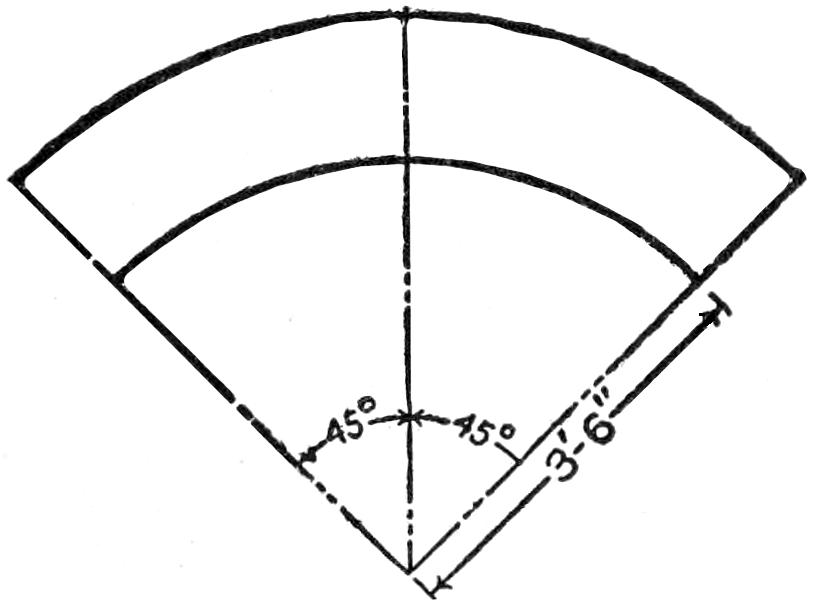
METHOD OF LAYING OUT CURVED
SECTION
Fig. 6

LEFT SWITCH
Fig. 7
RIGHT SWITCH
Fig. 8
Lay Out the Switches and Curves, Full Size, and Fit the Rails to the Curves Accurately
The curved sections may be made from rails similar to those described above, but some difficulty will be experienced in bending them into a curve because of the necessity of bending the lower flange on edge. The difficulty may be overcome by crimping in the inner edge of the lower flange and expanding the outer edge by hammering it on a smooth surface. The radius of the curve to which the inner rail should be bent in order to give a section of convenient length, and not too abrupt a curve, is 21 in. The circumference of such a circle is approximately 132 in., which, divided into eight sections, gives 16¹⁄₂ in. as the length of the inner rail of each section. Since the tread of the track is 2 in., the radius of the curve of the outer rail will be 23 in. The circumference of the circle formed by the outer rail is 145 in., which divided into eight sections gives 18¹⁄₈ in. as the length of the outer rail of each section. These curved rails may be mounted on sleepers, their ends being held in place, and the various sections fastened together, just as in the case of the straight sections.
Some trouble may be experienced in getting the curved rails properly shaped, and it would be a good plan to lay them out full size by drawing two circles on a smooth surface having diameters of 42 and 46 in., respectively, and divide each of the latter into eight equal parts. The form of the curve between these division lines and the lengths of the curves will correspond to the shape and lengths of the rails forming the curved sections of the track. The pieces should be cut slightly longer than required, and after[245] they are bent into shape their length can be determined precisely and extra portions cut off. Each curved section will correspond to ¹⁄₈ of the complete circle, or 45°, as shown in Fig. 6.
The switches for the track may be of two kinds: left and right. They are named according to whether the car is carried to the left or right of the main track with reference to the direction in which the car moves in entering the switch. A left switch is shown in Fig. 7, and a right switch in Fig. 8, the direction of movement being indicated by the arrows.
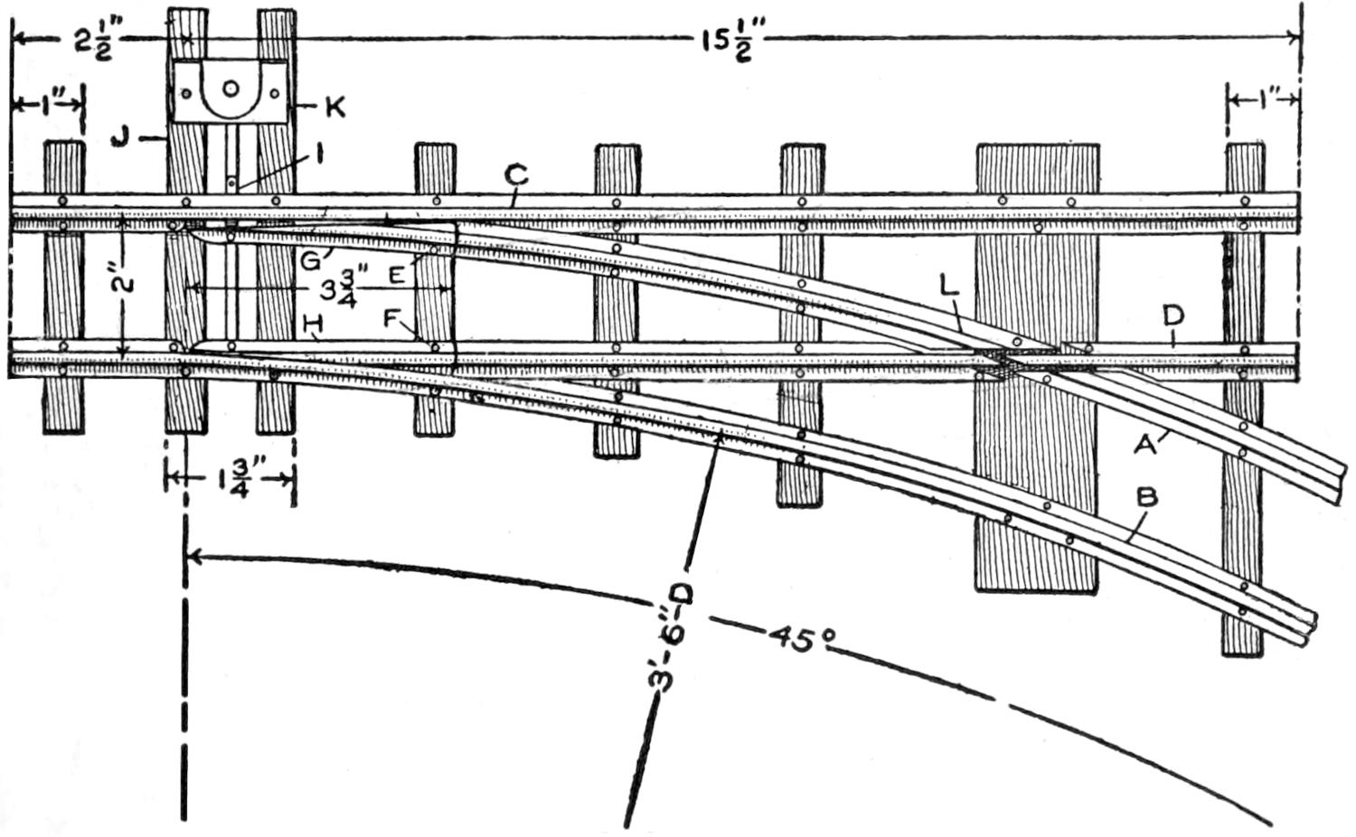
DETAILS OF SWITCH
Fig. 9
The Crossings of the Rails must be Fitted Carefully, and the Movable Sections G and H Arranged to Make the Proper Contacts
A detailed drawing of a right switch is shown in Fig. 9. Rail A corresponds in form and length to the outer rail of one of the curved sections previously described; rail B corresponds to the inner rail of one of the curved sections except that 2¹⁄₂ in. of straight rail is added at the left end. Rail C is a straight portion of rail, 18 in. in length, with a part of the base cut away at the switch, and rail D is a section of straight rail, 15¹⁄₂ in. in length, with the base cut away where it crosses rail A. The ends of rails D and A are hinged at the points E and F, 3³⁄₄ in. from the left end, with pins driven into the ties. The outside edges of the pieces G and H are filed off so they will fit up against the rails C and B respectively. Both the pieces G and H are attached to a strip of fiber insulating material, I, at their left-hand ends, in such a way that when the piece H is against the rail B, the piece G is away from the rail C about ³⁄₁₆ in.; when the end of the piece G is drawn over against the rail C, the end of the piece H is drawn away from the rail B about ³⁄₁₆ in. With these two combinations the car may be made to move along the main track or to the right on the curved track. The two long sleepers J and K are to provide a mounting for the switch-control lever and signal.
The rail A is not continuous where the rail D crosses it, but is broken as shown in the figure. A small notch should be cut in the surface of the rail D where it crosses the rail A, for the flange of the car wheels to roll through when the car is moving onto or off the switch. The sections of the rails A and D must be connected electrically. Rail A must be connected to rail C, and rail B to rail D.
It is obvious from an inspection of Fig. 9, at L, that rail D will be connected to rail A when the car is on the switch, the car wheels passing over the point L, and a short circuit will result. This may be prevented by insulating the short section of the rail D at this point from the remainder of the rail, but the length of the insulated section must not be greater than the distance between the wheels on one side of the car; otherwise the circuit through the motor would be broken. If this is the case, and the car stops on the main track with both wheels on the insulated section, it would be impossible to start the locomotive until one wheel was moved to a live part of the rail.
The switch control is shown in Fig. 10, and the letters C, G, and I correspond to those given in Fig. 9. A ¹⁄₈-in. rod, about 4 in. in length, is bent[246] into the form shown at M. It is mounted in a frame, the details of which are shown in Fig. 11. A small arm, N, with a hinged handle, O, is soldered to the rod, after it is placed in position in the switch frame. The arm N and the lever P should be parallel with each other. If properly constructed, the handle O will drop into the notches in the top of the switch frame, and prevent the rod M from turning. A connection should be made from the lever P to the end of the piece I, which will result in the switch being operated when the rod M is rotated one-fourth of a turn. After this connection is made, the frame of the switch should be fastened to the ends of the long sleepers, which were provided when the track part of the switch was constructed. Two small disks, mounted at right angles to each other, will serve as signals when properly painted, or as an indication of the open or closed position of the switch.
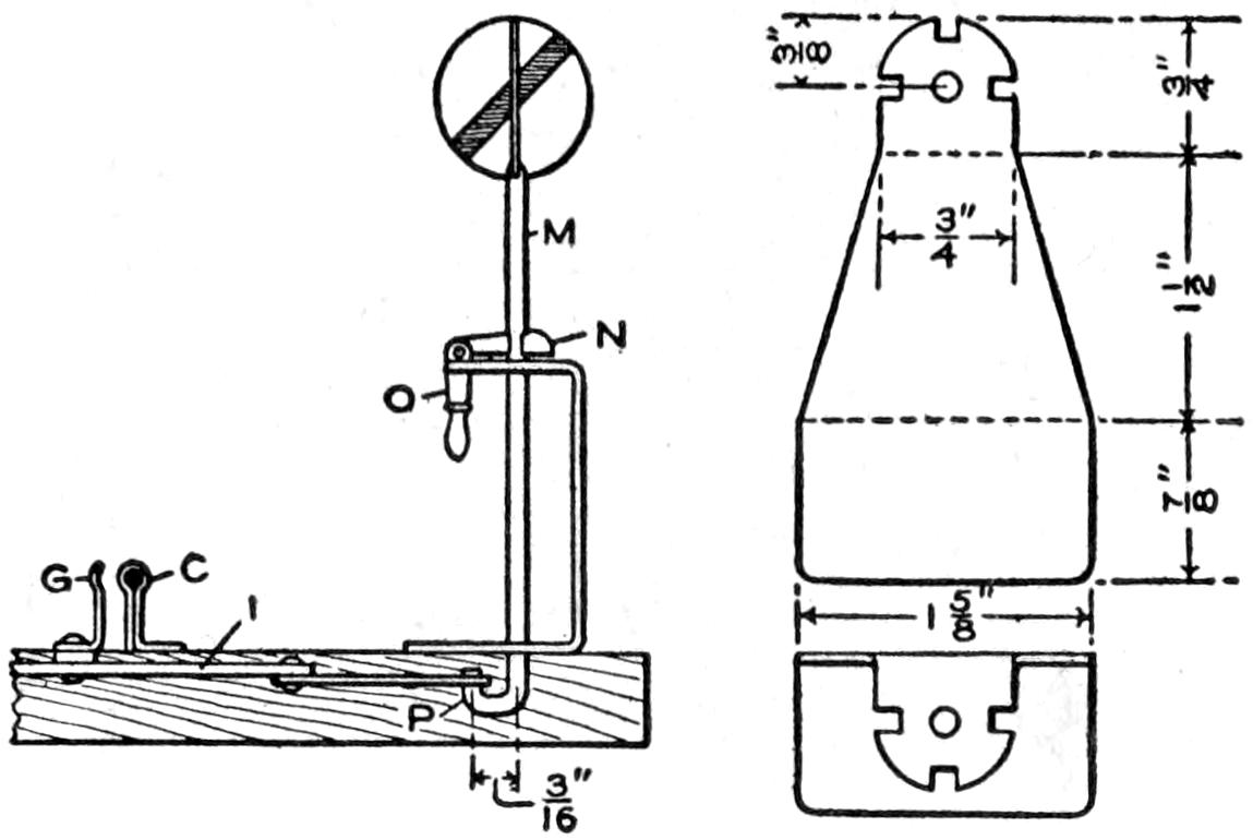
SWITCH CONTROL
Fig. 10
TOP VIEW
SWITCH FRAME
Fig. 11
The Signals Indicate the Open or Closed Condition of the Switch by the Small Disk, Which is Regulated by the Lever Switch Control
The speed of the car on the track may be controlled by inserting resistance in series with the battery or source of electrical energy, or by altering the value of the voltage between the rails, by changing the connections of the cells forming the battery. The direction of movement of the locomotive cannot be changed unless the car is turned end for end, or the connections of the armature or field winding—not both—are reversed. The switch on the bottom of the locomotive reverses these connections.
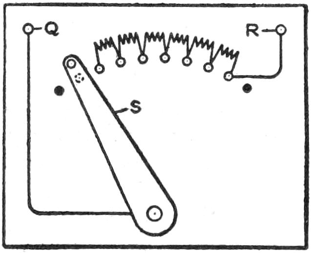
Fig. 12
A small rheostat, which will give the desired resistance, may be constructed as follows: Obtain a piece of hard wood, 4 by 5 in., and ³⁄₈ in. in thickness. Lay out a curve on this piece, as shown in Fig. 12 by the row of small circles. Procure eight round-headed brass machine screws, about ¹⁄₈ in. in diameter and ³⁄₄ in. in length, and 16 nuts to fit them. Drill eight ¹⁄₈-in. holes along the curve, spacing them ³⁄₈ in. apart. File the heads of the screws off flat and mount the screws in these holes. Make a metal arm, S, and mount it on a small bolt passing through a hole drilled at the center from which the curve was drawn, along which the screws were mounted. This arm should be of such a length that its outer end will move over the heads of the screws. Mount two binding posts, Q and R, in the upper corners of the board and connect R to screw No. 8, and Q to the bolt holding the arm S in place. Connect small resistance coils between the screws, starting with screw No. 2; screw No. 1 corresponds to an open circuit and is shown in contact with the arm S. Two stops, indicated by the black spots, should be provided, to prevent the arm from moving back of screw No. 1 or beyond screw No. 8. The board may now be mounted on a suitable hollow base, and the rheostat is complete.
Two binding posts should be mounted on the ties of one section of the track, and one of them electrically connected to each of the two rails, which will give an easy means of making the necessary electrical connections to the source of energy. After careful examination, to make certain that the locomotive is in running order, a test run may be made. If the locomotive operates properly and difficulty is experienced when it is placed upon the track, check up thoroughly on all rail connections, insulations, and other elements in the electrical equipment.[247] Cars of a proper gauge may be coupled to the locomotive, and “runs” made as extensively as the track system will permit.
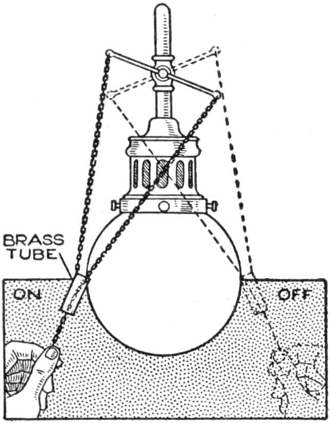
Annoyance through inability to locate quickly the proper chain for lighting a gas lamp in the dark was overcome by fitting a small brass tube to one of the chains as shown in the illustration. The tube was soldered to the chain by which the light is turned on and the other chain passes through the tube and is grasped below it. To turn on the light, it is only necessary to slide the hand along both chains and to grip the tube, drawing on the chain attached to it. To turn the light off, the exposed end of the other chain is drawn.—Thomas W. Benson, Hastings upon Hudson, N. Y.
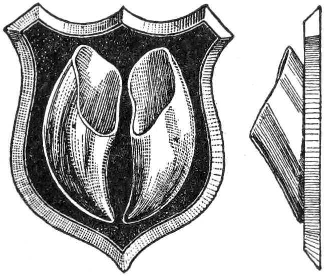
A match holder made of the horn shell of cattle hoofs mounted on a wooden shield, as shown in the sketch is both ornamental and useful. One of the pockets holds the unused matches and the other the burnt ones. The hoofs were cleaned thoroughly and polished and the edge of the shield was beveled off and varnished in the natural color of the wood. The front was lacquered black and also varnished.
¶A small flat piece of wood is convenient for pointing up an eraser.
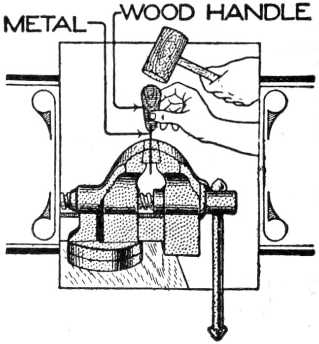
A slender piece of flat, or round, metal may be driven into a wood handle without breaking the wood or bending the metal, if it is placed in a vise and the wood part driven onto the small portion projecting from the jaws of the vise. Repeat the operation until the metal is driven far enough into the wood.
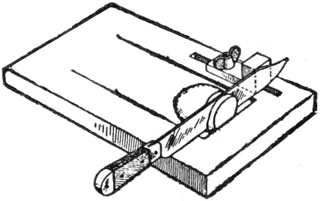
The board illustrated was suggested by a device used by a “sandwich man,” and proved practical for use in the home and especially in the camp. Potatoes, or other articles of food to be sliced, are placed in the hollow portion of the board and moved against the edge at the right, under the knife. The guide, which may be adjusted by means of the wing nut, permits slices of varying thickness to be cut.—Robert C. Knox, St. Petersburg, Fla.
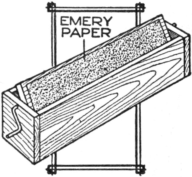
Pencils may be pointed without spreading the dust from them by the use of the device shown in the illustration. A piece of emery paper is fixed to one side of the cover of the box. By turning over the cover with a handle, after a pencil has been pointed, the dust may be dropped into the box and removed from time to time.—Sidney Block, Detroit, Mich.
[248]

A
B
A Case-Knife Blade Bent and Fastened in a Broom Handle Makes an Excellent Weeding Tool
A handy weeding tool may be made of an old case knife—one of the kind having a wood handle is the best. Remove the handle sides and heat the blade about 1 in. from the end, then bend it at right angles as shown at A. Ream out the rivet holes in the handle large enough to allow screws, about 1 in. in size, to enter. Procure an old broom handle and saw a slot in one end deep enough to receive the knife shank, and fasten it with screws, as shown at B. This makes an excellent tool for removing weeds from beds of young radish, lettuce and other plants, as it is possible to get close to the plant stem without injuring it.—Contributed by L. G. Burnand, Lyons, Iowa.
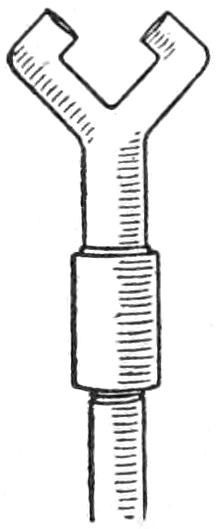
A
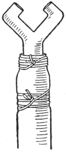
B
An acetylene burner makes a first-class spray nozzle, even though the lava tips are broken off level with the metal. The burner may be secured on a short piece of pipe, as at A, and this inserted in a hose, or it may be pushed into a hose and wound with wire, as shown at B.
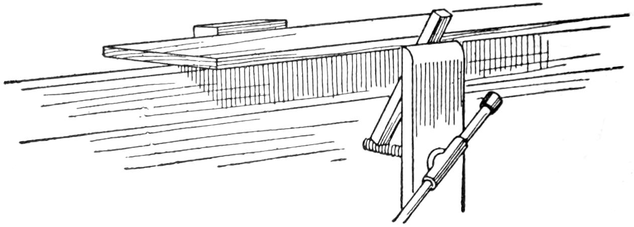
A Block on the Bench and a Stick in the Vise Served as Jaws of a Wide Opening
Having occasion to cut a groove on the surface of a board too wide for the vise, I rigged up the arrangement shown to hold it. The board was laid on the bench with the edge slightly projecting, then I nailed a block firmly to the bench, close to the edge of the board, and placed a stick in the vise as shown. When the vise screw was turned up, the board was gripped solidly.—Contributed by S. H. Bosuston, Victoria, B. C.
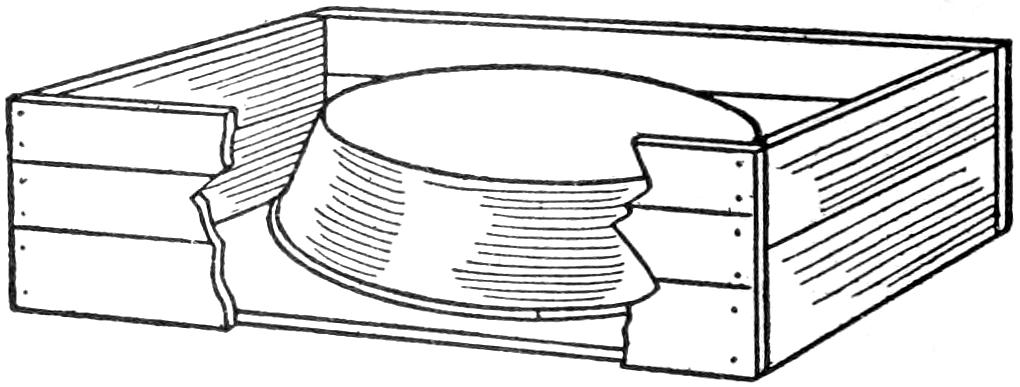
An Ordinary Pan Placed in a Shallow Box Makes the Form for a Concrete Vessel
An excellent water or feeding pan for small chicks can be made of concrete. Take an old pan and place it in an inverted position in a shallow box, as shown in the sketch, then mix the concrete and pour it over the pan. When the cement sets, turn it over and a pan will be had that small chicks can climb out of, should they get into it.
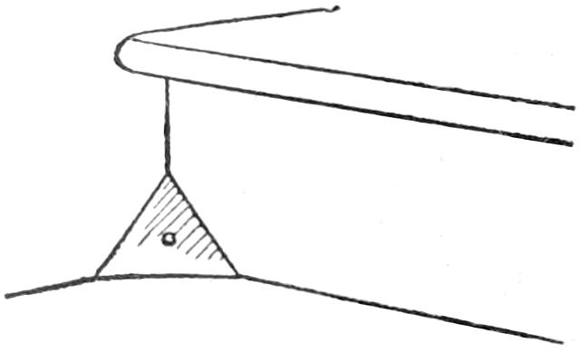
The hardest part of a room or stairway to clean is the corners, and these always collect a good quantity of dirt. Instead of removing the dirt each time, a better plan is to fix the corner as shown in the illustration. A triangular piece of brass or copper, 2 in. on each side, is fastened into the corner with one nail through the center. These metal pieces are especially desirable in public buildings.—Contributed by Abner B. Shaw, N. Dartmouth, Mass.
[249]

There are very few electrical experimenters who can afford a Wheatstone bridge for measuring resistances, and yet, if one is to gain any knowledge from his experiments, it is very necessary to know what resistance is being used, particularly in handling 110 volts. The amateur will find the following method very useful.
There are several brands of lead pencils, the leads of which have a resistance of 200 to 300 ohms, while others have comparatively little resistance. Soak several pencils—preferably the large kind carpenters use—in water over night so that the leads may be removed without breaking. Connect up two 40-watt lamps in series and note how they burn. Then replace one lamp with a lead and note the relative intensity with which the remaining lamp burns. If the lead is of a sufficiently high resistance it will cut down the illumination about as much as the additional lamp.
Having selected a lead, mount it on a suitable board, holding it in place by clamping each end under a strip of brass held down with wood screws. Next screw in place two porcelain receptacles and place three binding posts in position, all as shown in the sketch. Connect up as indicated, and attach a short length of flexible cord, with a metal tip on the free end, to one terminal of the central receptacle. Procure a cheap 75-ohm receiver and connect it to the two ends of the pencil lead. Finally glue on a paper scale.
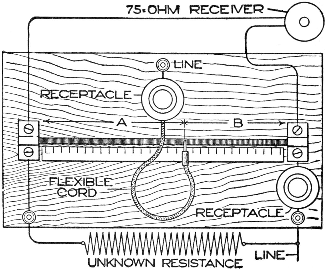
The Lead Taken from a Lead Pencil and Used as a Means of Measuring Resistance
To operate, place a high-resistance lamp in the center receptacle—say, a 15-watt lamp—to prevent heating, and almost any lamp of known wattage in the other receptacle. From the rating of this lamp the resistance may at once be determined by Ohm’s law. Thus, at 110 volts, a 25-watt lamp will have a resistance of 484 ohms; a 40-watt lamp 300 ohms, and a 60-watt lamp, 200 ohms. Connect the unknown resistance, as shown in the drawing, and move the metal tip on the end of the flexible cord back and forth along the pencil lead until a point is reached where no sound is emitted by the receiver. This point will be very well defined, and as the connection is moved away from it in either direction the sound will increase rapidly. Note the reading on the scale, and then if a 40-watt lamp is used in the end receptacle, the unknown resistance will be = 300 A B. The resistance of the center lamp does not enter into the computation, but by changing the lamp in the end receptacle, another set of figures may be obtained, and a means had to secure increased accuracy.
[250]
The controller described is very similar in operation to the types of controllers used on electric automobiles, and its operation may be easily followed by reference to the diagrammatic representation of its circuits, and those of a two-pole series motor to which it is connected, as shown in Fig. 1. The controller consists of six flat springs, represented as small circles and lettered A, B, C, D, E, and F, which make contact with pieces of narrow sheet brass mounted on a small wood cylinder, so arranged that it may be turned by means of a small handle located on top of the controller case in either direction from a point called neutral, which is marked N. When the cylinder of the controller is in the neutral position, all six contact springs are free from contact with any metal on the cylinder. The contacts around the cylinder in the six different horizontal positions are lettered G, H, J, K, L, and M. There are three different positions of the controller in either direction from the neutral point. Moving the cylinder in one direction will cause the armature of the motor to rotate in a certain direction at three different speeds, while moving the cylinder in a reverse direction will cause the armature to rotate in the opposite direction at three different speeds, depending upon the exact position of the cylinder. These positions are designated by the letters O, P, and Q, for one way, and R, S, and T, for the other.
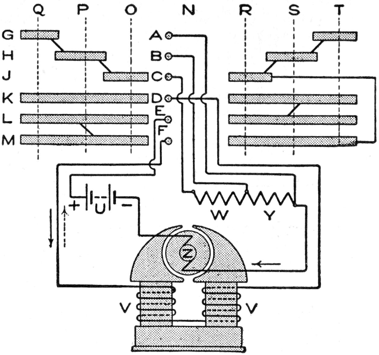
Fig. 1
Diagram of the Electrical Connections of a
Controller to a Two-Pole Series Motor
Supposing the cylinder to be rotated to the position marked O, the circuit may be traced from the positive terminal of the battery U, as follows: To contact spring E, to strip of brass L, to strip of brass M, to contact spring F, through the field windings VV, to contact spring D, to strip of brass K, to strip of brass J, to contact spring C, through resistance W and Y, to armature Z, through armature to the negative terminal of the battery. Moving the cylinder to the position P merely cuts out the resistance W, and to the position Q, cuts out the remaining resistance Y. The direction of the current through the armature and series field, for all positions of the cylinder to the left, is indicated by the full-line arrows. Moving the controller to the positions marked R, S, and T, will result in the same changes in circuit connections, as in the previous case, except the direction of the current in the series field windings will be reversed.
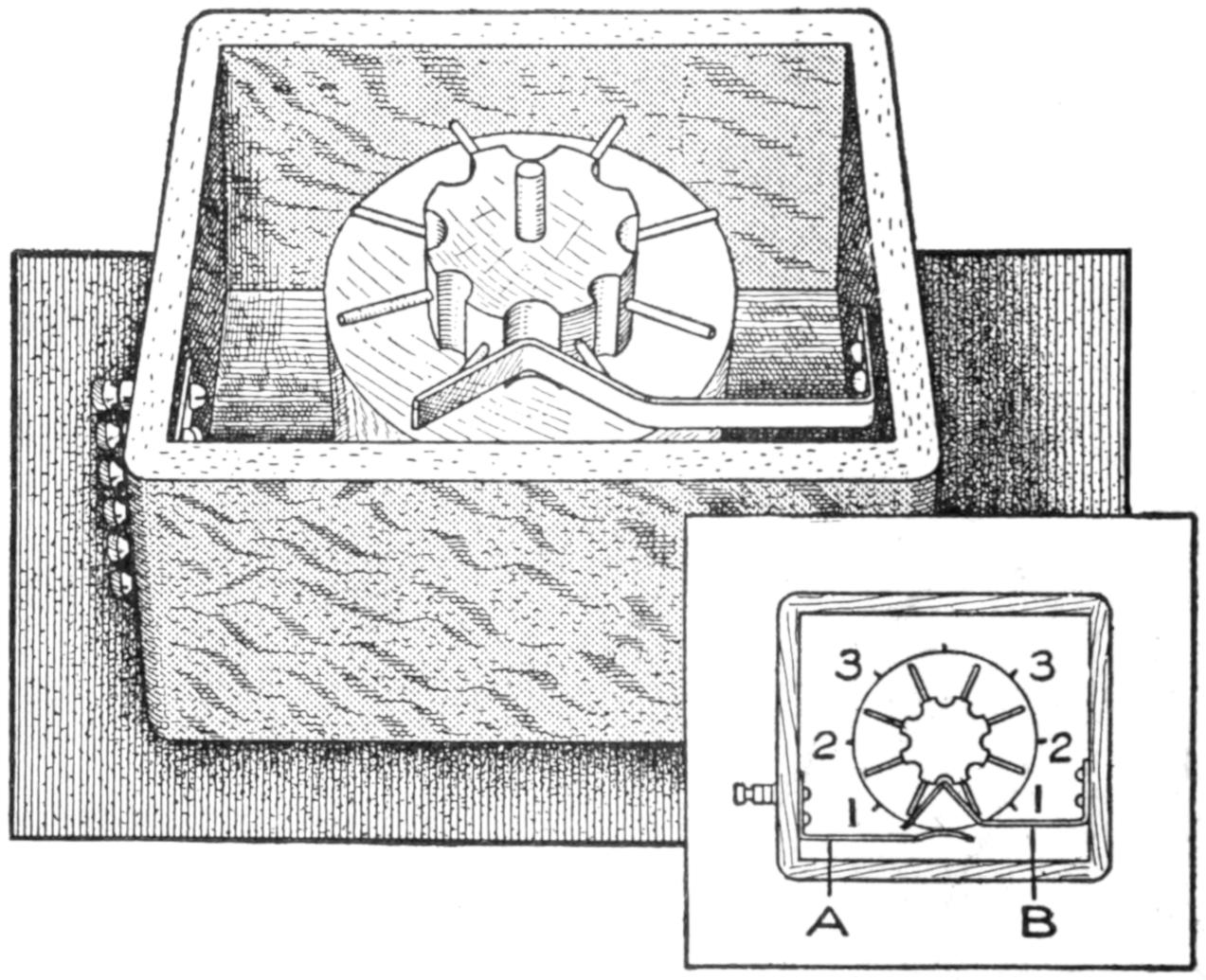
Fig. 2
Upper-End View of the Controller, Showing the
Manner of Attaching the Springs
The construction of the controller may be carried out as follows: Obtain a cylindrical piece of wood, 1³⁄₄ in. in diameter and 3¹⁄₈ in. long, preferably hard wood. Turn one end of this cylinder down to a diameter of ¹⁄₂ in., and drill a ¹⁄₄-in. hole through its center from end to end. Divide the circumference[251] of the small-diameter portion into eight equal parts and drive a small nail into the cylinder at each division point, the nail being placed in the center of the surface lengthwise and perpendicular to the axis of the cylinder. Cut off all the nail heads so that the outer ends of the nails extend even with the surface of the outer, or large-size, cylinder. Divide the large part into eight equal parts so that the division points will be midway between the ends of the nails, and draw lines the full length of the cylinder on these points. Divide the cylinder lengthwise into seven equal parts and draw a line around it at each division point. Cut some ¹⁄₈-in. strips from thin sheet brass and mount them on the cylinder to correspond to those shown in Fig. 1. Any one of the vertical division lines drawn on the cylinder may be taken as the neutral point. The pieces may be mounted by bending the ends over and sharpening them so that they can be driven into the wood. The various strips of brass should be connected electrically, as shown by the heavy lines in Fig. 1, but these connections must all be made so that they will not extend beyond the outer surface of the strips of brass.
A small rectangular frame is made, and the cylinder is mounted in a vertical position in it by means of a rod passing down through a hole in the top of the rectangle, through the hole in the cylinder and partly through the bottom of the rectangle. The upper part of the rod may be bent so as to form a handle. The rod must be fastened to the cylinder in some convenient way.
Make six flat springs similar to the one shown at A, Fig. 2, and mount them on the inside of the rectangle so that they will correspond in their vertical positions to the strips of brass on the cylinder. Six small binding posts mounted on the outside of the box and connected to these springs serve to make the external connections, and they should be marked so that they may be easily identified.
A flat spring, ¹⁄₄ in. wide, is made similar to the one shown at B, Fig. 2. Mount this spring on the inside of the rectangle so it will mesh with the ends of the nails in the small part of the cylinder. The action of this spring is to make the cylinder stop at definite positions. The top of the case should be marked so that the position of the handle will indicate the position of the cylinder. Stops should also be provided so that the cylinder case cannot be turned all the way around.

A very neat and workmanlike push button may be made in the following manner: Procure an unused tan-shoe eyelet with an opening about ³⁄₁₆ in. in diameter, and at the proper point drill a hole into the board in which the button is to be set. Force the eyelet in flush, using a little shellac to hold it in tightly. For the button proper, polish off and round one end of a piece of brass rod of a diameter that will move freely up and down in the eyelet. Solder a small piece of sheet brass across the lower end to keep it from coming out, then adjust and fasten on the two contact pieces, all as indicated in the sketch. The larger piece should be quite springy so as to bring the button back each time. The connections may be made by slipping the wires under the heads of the two wood screws that hold the contact pieces in place.
As every experimenter knows, it is almost impossible to drill a hole in the varnished base of an instrument without leaving a raw edge. Under such circumstances, when it is desired to make an opening for conducting cords, and the like, simply drill a hole with an ordinary drill and then set in a small shoe eyelet, which immediately presents a very finished appearance.
¶Vaseline, with a little powdered gum camphor added and heated over a slow fire, makes an excellent rust preventive for tools.
[252]
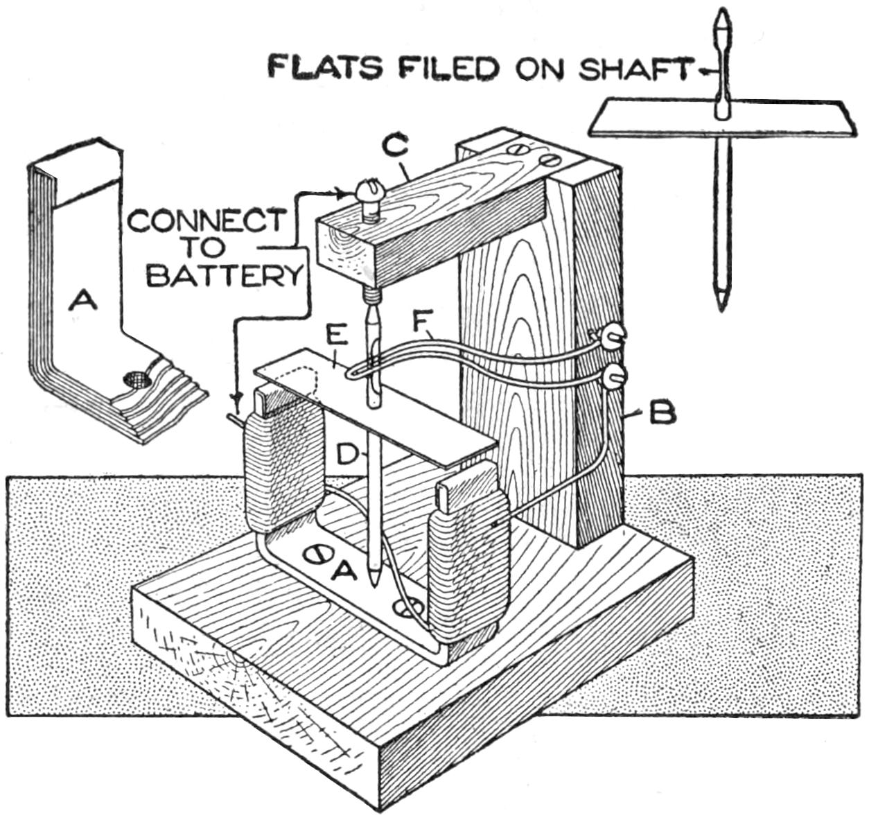
The Motor is Constructed of Pieces of Tin, a Nail, and Some Wood Blocks
The illustration shows a small electric motor of such simple construction that it can be easily made from odds and ends to be found in any amateur workshop. Cut six strips, ¹⁄₂ in. wide and 3¹⁄₂ in. long, from an old tin can, and bend them together into a U-shape. This forms the magnet A. The outside piece should be a trifle longer than the others so that its ends can be turned over the other ends to keep them all in place. Screw this down on a small wood base. At one side of the wood base, fix an upright, B, and on top, a light wood bracket, C, to take the upper bearing of the motor. The shaft D is simply a wire nail with the head filed off and filed to a point. Drive it through a 1¹⁄₂-in. length of the same kind of material as used for the magnet. This forms the rotating armature E.
Make a slight indentation with a center punch, or strong nail, exactly in the center of the base portion of the magnet to take the lower end of the shaft. For the upper bearing file the end of a brass screw off flat and make a similar indentation with a center punch, or by a few turns of a small drill. This screw should be adjusted in the bracket until the shaft rotates freely with the armature just clearing the tips of the magnet. Wind about 40 turns of fairly thin cotton-covered copper wire—No. 24 or 36 gauge is suitable—around each limb of the magnet, first covering the latter with paper, to prevent the possibility of short-circuiting. The windings should be in opposite directions so that the connecting piece of the wire from one coil to the other passes across diagonally as shown in the illustration.
The brush F is formed by doubling up one of the free ends of the windings after removing the cotton covering and fixing it firmly with two screws to the side of the upright. After attaching, it should be bent until the outer end bears lightly on the shaft. Remove the shaft and at the point where the brush touched, file two flat surfaces on opposite sides of the nail in a direction at right angles to the longitudinal center line of the armature. On replacing the shaft the brush should be adjusted so that it makes contact twice in a revolution and remains clear at the flat portions. Connect up to a battery, one wire to the screw at the top of the motor and the other end to the open end of the windings. Give the armature a start and it will run at a terrific speed.—Contributed by Morris G. Miller, New Rochelle, N. Y.
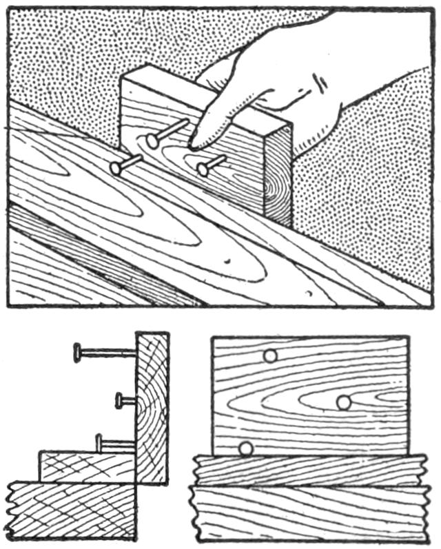
A convenient gauge can be quickly made by using a block of wood and an ordinary nail, or several nails for different widths can be placed in one block. Drive the nails straight into the block until the distance between the head and block is the required distance to be gauged. The rim of the nail head makes the mark as the block is drawn over the wood surface—Contributed by E. P. Haldeman, Balboa, Canal Zone.
[253]

Where a high degree of accuracy is neither desired nor necessary, a very satisfactory ammeter may be made at the cost of a few cents, and without using hairsprings, permanent magnets, or other articles usually not at hand.
The actuating device consists of a small coil of coarse, insulated wire, with a bundle of soft-iron wires for a core, which attracts a curved, soft-iron, wedge-shaped armature. The moving system is so balanced that the armature will hang as illustrated when no current is passing. On account of its shape, the higher the armature rises, the more iron it presents to the influence of the magnet, and, on the other hand, the greater will be the effect of gravity. The advantage of this type of control is the elimination of the irregular readings of the scale, due to the law of inverse squares, that usually follow when any method depending upon a variable distance is used. Further, the readings can be had as desired by altering the taper of the armature, its thickness, or its distance from the magnet, and also by adding a small weight of nonmagnetic material at the bottom. As most commercial circuits supply alternating current, the friction of the bearings does not affect the readings, since the alternations set up a decided vibration in the entire moving system, thus eliminating static friction.
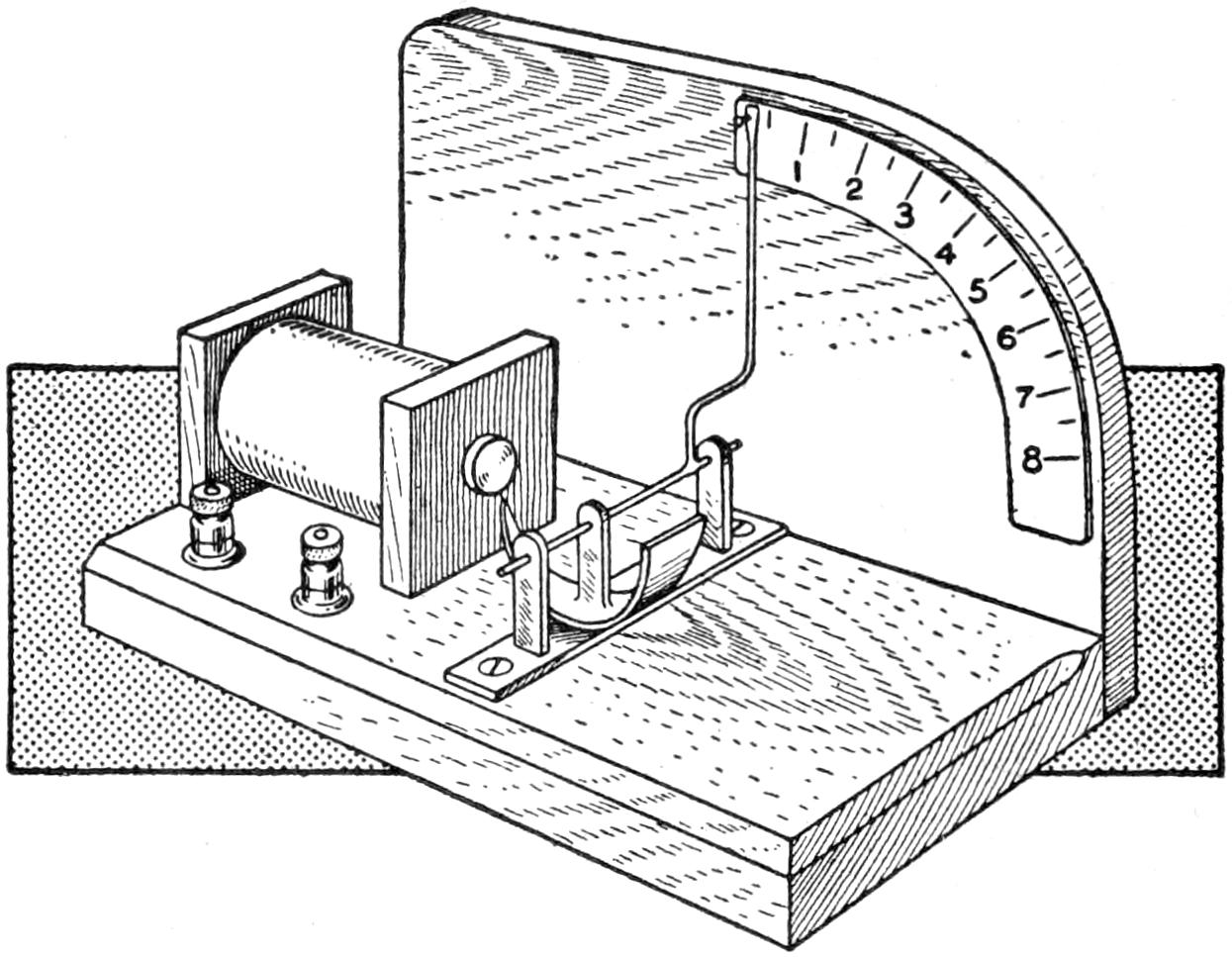
A Very Satisfactory Ammeter for Use Where Accuracy is Not Desired or Necessary
In view of the variations above referred to, it will be evident that it is not very essential of what dimensions the apparatus is made. The instrument that I use has a base measuring 2¹⁄₂ in. by 5 in. The coil is built on a tube of glued paper, and contains about 15 ft. of No. 16 gauge wire. The terminals consist of the brass bolts taken from discarded dry cells. A steel sewing needle serves as a shaft, and a piece of wire for the pointer. The various joints are made with soft solder, and suitable stops are provided to keep the armature from shifting laterally. In calibrating, a blank scale should be glued in position and as many 55-watt lamps as possible arranged so that they can be placed in the circuit, one at a time. On a 110-volt line, each lamp added will mark a half-ampere point. If a sufficient number of lamps to carry the scale high enough cannot be secured temporarily, a resistance of some 20 or 30 ohms should be placed in the circuit without any lamps. Note the reading in amperes on the scale thus far constructed, and then begin adding the lamps again, making a mark on the scale as each lamp is added. In this manner a scale may be built up sufficiently accurate for all practical purposes.
If two identical coils are made in[254] place of one, the additional coil can be placed in parallel with the instrument as a shunt, thus doubling its capacity and making it necessary, of course, to multiply all readings by two.
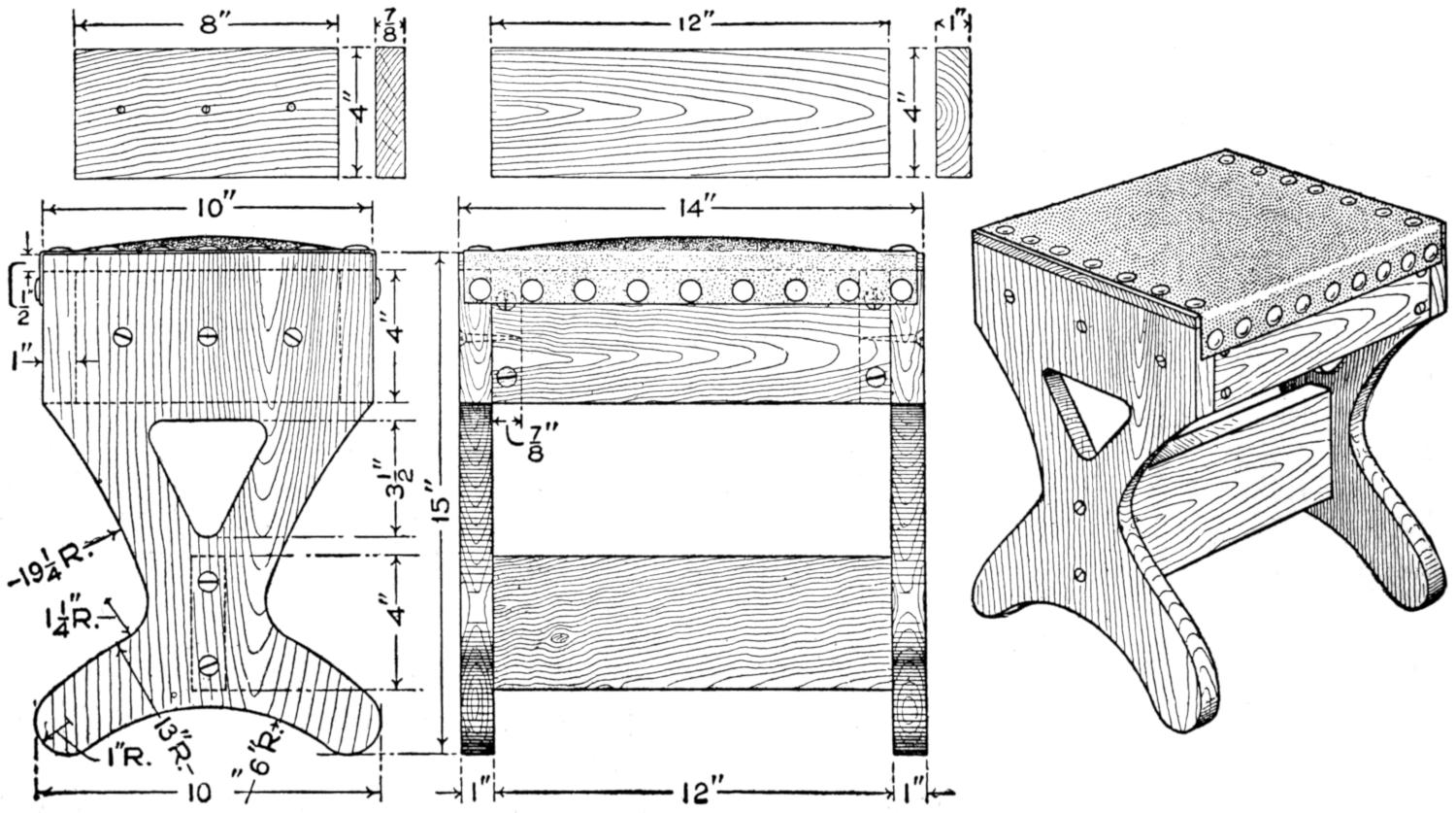
Footstool in Mission Finish with a Leather Top
The material necessary for the footstool shown in the illustration is as follows:
2 end pieces, 1 by 10 by 15 in.
3 cross braces, 1 by 4 by 12 in.
2 end braces, ⁷⁄₈ by 4 by 8 in.
1 top board, ¹⁄₂ by 10 by 14 in.
1 piece of leather, 11 by 16 in.
Round-head wood screws and nails.
The two end pieces should be marked to a suitable pattern, and may be cut out with a scroll or coping saw, or, if these are not available, with a keyhole saw. The center opening should first be bored at one end and then cut out with the saw. The three long braces should be accurately squared and finished at the ends; the rigidity of the stool depending on this work. The seat consists of a box form with the open side down. The top is a ¹⁄₂-in. board, 8 in. wide by 12 in. long; the sides are formed by two of the long braces, and the ends are the short braces. This box is securely put together with nails, and then screwed in position with round-head wood screws so as to be flush with the top edge of the end pieces. The lower brace is secured in place with screws. In putting on the leather top, ¹⁄₂ in. should be turned under at each end, and 1¹⁄₂ in. brought down on each side. This will provide sufficient looseness to pad the seat properly. Large round-headed brass nails can be used, producing a neat appearance. The stool is then ready for a suitable stain or finish.—Contributed by Stanley B. Furbeck.
While we were filling our barrels at the cider mill it was discovered that one barrel had no stopper. This did not bother the cider-mill man, who took up a sound apple of about the dimensions or diameter of the bunghole and squeezed it in, tight as a cork, then shaved it off flush with the barrel staves. We started Home and rolled it around a great deal with the other barrels, yet it held as tightly as any wood stopper.—Contributed by A. A. Kelly, Frazer, Pa.
¶An open umbrella placed on the floor upside down makes an excellent receptacle for catching dirt and plastering when installing electric fixtures.
[255]
[The various materials referred to in this article by number or size were described in detail in an article on “A Reed Basket,” in the Boy Mechanic, Book 2, page 257.]
Reed furniture has become very popular within the last few years, and the newer designs and methods have been so attractive as to place this constructive effort among the handicraft series of modern art. It is possible so to analyze, simplify, and illustrate this work as to make it feasible for amateurs, and at the same time there are possibilities which involve problems that may try the ability of the skilled workman. In other words, there are possibilities of progress in this kind of furniture making. There are places where careful weaving is the principal aim; again particular attention will be given to corners, or, perhaps, a nicety of modeling will be found necessary to bring out the proper curves involved.
Each piece of reed furniture has a framework, usually of dowels, but it may also be made of boards in such models as small tables, dressers, bedsteads, chests, etc. The board construction is more often covered with flat reed. In footstools there are both kinds of framework. The illustrations show the same parts marked with the same letters throughout the series of sketches.
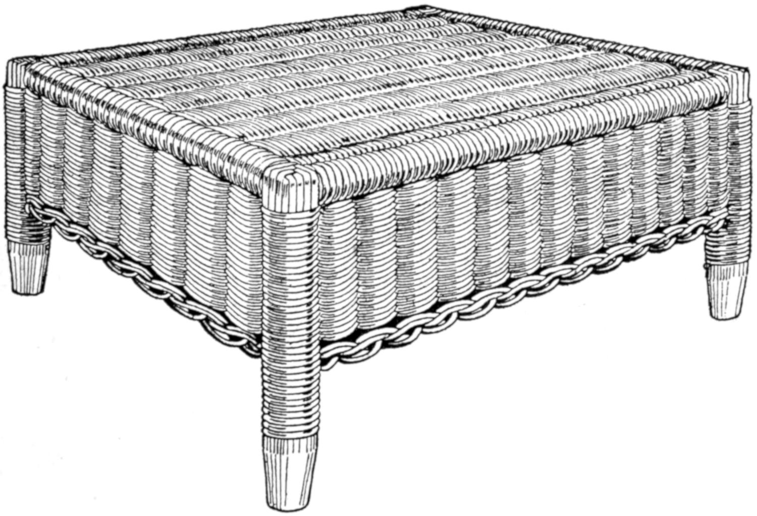
The Framework of the Stool is Made of Large Dowels, Then Covered with Windings of Reed and a Woven Reed Top and Apron
The framework of the stool is shown in Fig. 1, in which the rails and posts are made of dowels, ³⁄₄ in. in diameter, and the braces of dowels, ⁵⁄₈ in. in diameter. It will be noticed that the posts extend to the top of the frame for strength in this manner of construction. If the rails rested on top of the post S, the nails would have to be driven into the end grain of the wood, which makes the strength depend entirely on the holding power of the nail in this position, as there is no binding of the upper part to the posts in the weaving. With the post extending to the top, the nail passes through the upper part of the post and into the end grain of the rails, and the rails are bound together horizontally by the weaving.
The material for the frame consists of the following dowel stock: two pieces for rails, ³⁄₄ in. by 14 in. long; two pieces for rails, ³⁄₄ in. by 9 in. long; four posts, ³⁄₄ in. by 7 in. long, and two braces, ⁵⁄₈ in. by 17 in. long. These pieces are shown in Fig. 2. If notches are cut with a small saw, a coping saw preferred, in the ends of each rail and in the braces, as shown in Fig. 3, they will fit to the posts better and make a stronger joint. While different makers use a finishing nail; a barbed or corrugated, nail; or a cemented, or glue-coated, nail, I find the best to be an ordinary 4-penny nail, which answers the purpose well. Do not drive the nail through the posts without first drilling a hole with a ¹⁄₁₆-in. drill. A small hand or breast drill will be needed for this work.
Before nailing the frame together, the holes for the spokes in weaving should be drilled in the rails. The spokes may be No. 4 and the weavers No. 3 reed. The No. 4 reed requires a ¹⁄₈-in. hole. The hole for the top and end side spokes may be combined, as shown in Fig. 4. The dotted lines show the vertical and horizontal diameters, and E the outside and F the inside of the rail, one hole being represented as sawed in two. The spokes[256] for the top extend down and out at the ends, and each may be of one piece, 32 in. long. As there are no spokes at the top extending to the side pieces, short spokes must be inserted at the right time for the side weaving. The location of the holes in the side rails is shown in Fig. 2. The holes in the side rails may be drilled straight in the wood.
The pieces may now be nailed together to form the frame, as shown in Fig. 1. If the top of the side rails A are set about ¹⁄₁₆ in. below the tops of the posts, the weaving will be almost level, as the winding reed is thinner than the round reed. The braces D are halved at the center, on a slant, to bring their upper surfaces on a level when they are in place. The length of 17 in., as given in the material list, is not accurate, as sufficient length is given to allow the ends to be cut, in fitting them in place after the frame is assembled. The posts should stand vertical and square. Try the braces before nailing them in place, to see that they do not draw the frame out of shape.
The first operation in weaving is to cover the tops of the four posts, which is started as shown in Fig. 5. A short piece of winding reed, G, is first tacked in place. A round reed can be split if one is careful, in case winding reed cannot be obtained. Tacks used by shoemakers are just the thing for fastening these weavings in place. After fastening the weaving G in place, another, H, is put on in an opposite direction, whereupon J is fastened on the same as G, and so on, until the post is covered, as shown in Fig. 6. Perhaps a better way to cover the posts would be to tack all eight pieces on the post part C, and then weave them down together. It may not be necessary to tack them all on the rails.
After the corners are all covered, the end rails B are wound with the winding reed, the start being shown in Fig. 7, where the frame is shown in an inverted position. The reed is tacked, at K, to the side rail, and whenever the winding comes to a hole, a pencil mark is made to locate the hole later. This mark is shown at L. When the two end rails are wound, push a bodkin, or other steel point, in between the windings where the marks are located, to make way for the insertion of the spokes. It may appear to an observer that the spokes could be put in before the winding, but the winding cannot be properly done after the spokes have been inserted, as the windings would separate too much around them. The hole must be opened up through to the opposite side of the rail. Single spokes go through the rail, and they are only put through one end rail at first, as the weaving is much easier with one end of the spokes free, but, of course, they must be inserted in the other end before the weaving gets within 2 or 3 in. of that end. An extra spoke is inserted beside each spoke, as the weaving proceeds and after a strip has been woven ³⁄₄ in. wide. These short spokes are cut just long enough to fit in between the end rails. The weaving is done with a single weaver, and it is passed over and under double spokes as if they were one. When the weaver comes to the side rail, it is wound twice around the rail, to take up the space for the two strands across. If the weaver does not go twice around the side rails each time, either the weaving will take a curve or the side winding will be loose. The starting of the weaving is shown in Fig. 8, where the extra spokes are inserted along the side of each spoke that runs through the end rails.
After the spokes have been inserted in the opposite end rail and the weaving in the top completed, the braces and posts should be wound. Where the braces D connect to the posts C, three strips of the winding reed are passed around the post and tacked on both sides of the braces, as shown at M, Fig. 9. Where the braces cross, the winding passes around both pieces for a short distance, as shown at N. It is quite appropriate to use the brass caps O on this model, but on many stools their use has been discontinued and the winding continues down to within ¹⁄₈ in. of the bottom of the post.[257] In case the brass cap cannot be obtained, the winding may be used also on this model.
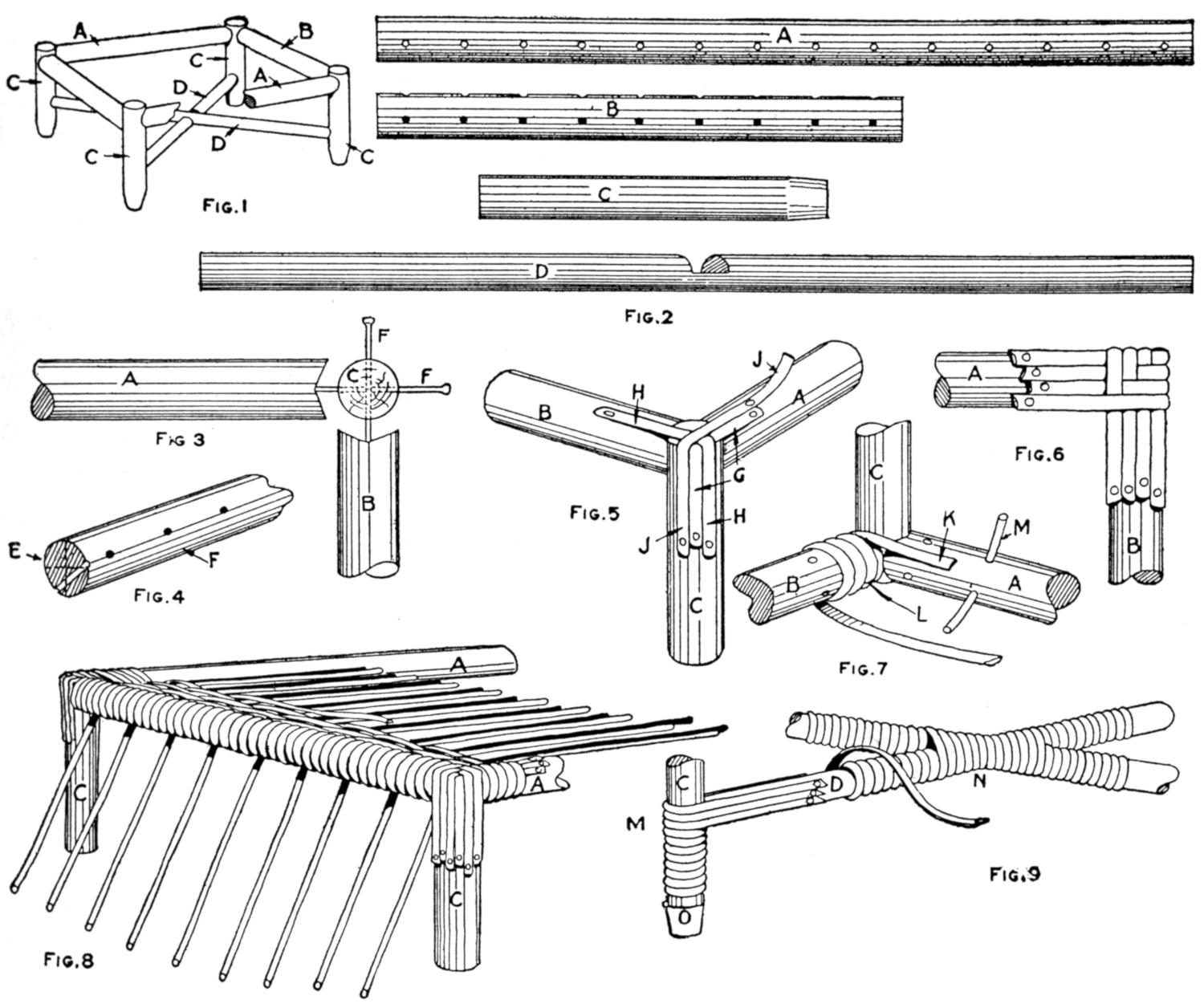
| Fig. 1 | Fig. 2 | ||||
| Fig. 3 | Fig. 5 | Fig. 6 | |||
| Fig. 4 | Fig. 7 | ||||
| Fig. 8 | Fig. 9 | ||||
Details of the Dowel Pieces, Showing Dimensions for Drilling the Holes to Admit the Spokes of Reed, Manner of Building the Framework, and How the Top is Woven
The side weaving is called the apron, and in this case the pairing weave is used. The short spokes will have to be inserted in the under side of the side rails, and the extra spokes are added after the weaving is started and a small strip woven. The pairing weave is shown in Figs. 10, 11, and 12. The two weavers are represented by the letters P and Q. The weaver P passes back of spoke T and out between T and U. The weaver Q is then used in the same manner, and so on, around the stool. When the post is approached the weaver that comes out between the last spoke and the post is passed around the post and in behind the next spoke on the other side. It will be seen in the pairing weave that the weaver behind is always thrown over the other weaver. This gives the appearance of a rope twist to the weaving, and also cinches it to the spokes and prevents slipping. Always pass the one weaver around the post twice to take up the space for the one that cuts across the corner. The weaving of the sides or apron is done with the object turned upside down, where it is in a good position for finishing off, which is sometimes called breaking down.
If the weaving has been carried far enough, the extra spokes are cut off even with the weaving, and the breaking down may be done as follows: The spoke R, Fig. 13, is shown turned down back of the spoke S, and S back of T and out. The spoke R, as shown in Fig. 14, is back of S, in front of T, back of U, and out between U and V, but as R is brought out, the spoke T is brought down back and parallel with R. Likewise the spoke S passes back of V, and U is brought down with it. The spoke T is brought back of W and V is brought down back of it. The short end of R is inserted under the[258] roll, between the roll and the weaving, and is left extending on the inside. If it is too long, it can be cut off close to the inside of the weaving. In Fig. 15, all the short ends are shown brought through to the back as far as the weaving is illustrated. At the corners, the posts are used as spokes. To finish the roll, the spokes will have to be inserted through the roll, to correspond with the rest of it; hence, the beginning of the roll should be left loose, as in Fig. 13.
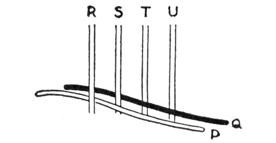
Fig. 10
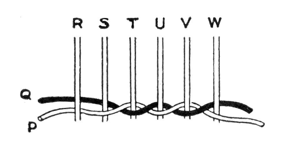
Fig. 11
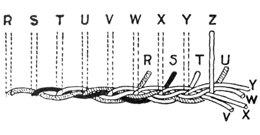
Fig. 15
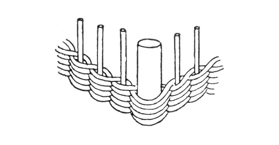
Fig. 12
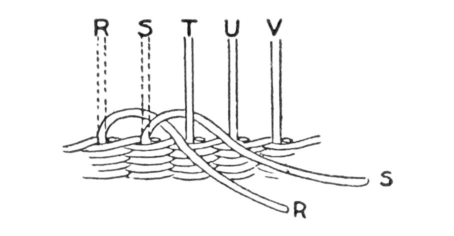
Fig. 13
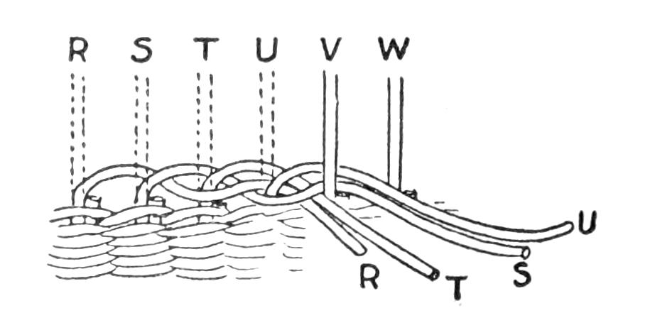
Fig. 14
The Weaving of the Apron is Done in the Same Manner as in Making a Basket, with the Break Down to Form the Edge
In weaving, the weavers should be kept wet, but not the spokes. Do not put the reed in water and leave it for any length of time, as it will become discolored. About 15 minutes will be sufficient to make the reed pliable, then it is best to have a sponge and bucket of water at hand, to dampen long weavers frequently by drawing the reed across the wet sponge. Besides being more workable, the wet reed, held in place until dry, stays curved in the form woven much better. Some workmen leave the reed in water for a long time and depend on bleaching to whiten it, but so much of the bleached work looks like a poor job of painting that it is much better to keep it white from the start. In case bleaching is found necessary, a little chloride of lime in water makes a good bleacher. Avoid making the solution too strong. It should be put on with a brush, so as to get it into the interstices of the weaving, whereupon the work is placed in the sunshine to dry.
Any kind of reed used will have some of the small hairlike fibers sticking out after the weaving is complete, and this should be singed off with a gas flame. A blowtorch is good for this purpose. Be careful not to scorch the weaving.
The instrument illustrated was designed to take the place of the two nails and a piece of string for drawing ellipses of different sizes. It is made of hard wood, preferably maple or beech, and consists of a bar with one fixed and one sliding head, the latter having a wedge clamp to hold it at any point desired on the bar.
In the ends of the heads are driven two coarse needles that have been broken off about ⁵⁄₈ in. from the eye end. These ends should be placed ¹⁄₈ in. from the inside of each head and the same distance from the bottom, and driven in until the eyes are each ¹⁄₈ in. from the surface. A piece of linen thread is run through the eye of the needle that is in the end of the sliding head and knotted to prevent its pulling out, and the free end is run through the needle eye on the fixed head. The thumb tack in the fixed head is to secure the free end of the thread. The[259] tack is driven in at an angle so that one edge sticks up enough to allow the thread to be pulled under it.
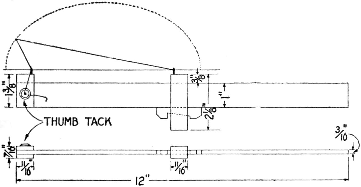
The Sliding Head can be Set so That Any Size Ellipse may be Drawn within the Scope of the Instrument
To operate the ellipsograph lay out the length of the major axis on a center line, then bisect the distance between these points and erect a perpendicular. On this line lay off half the minor axis, measuring from the center line; then from this point locate the foci by setting the dividers to half the major axis and scribing arcs of circles to cut the center line. Set the heads of the instrument so that the projecting needle ends will be the same distance apart as the foci, and clamp the sliding head with the wedge. Set the instrument so that the needle eyes will be exactly over the points where the foci are on the center line. A pencil, with a little groove filed ¹⁄₈ in. from the point, for the thread to run in, is set to half the minor axis and the thread is pulled taut and secured by the thumb tack. The pencil should be held perfectly perpendicular while scribing the line. The instrument must be reversed to draw the other half of the ellipse.
To draw an ellipse that will be an exact projection of a circle at any given angle it is necessary to determine the length of the major axis. This may be done by laying out the circle, either full size or to scale, and projecting two parallel lines equal to the diameter of the circle, or its scale, and connecting these lines with a line drawn to the required angle. The length of this line is the major axis.
¶Never run a glass cutter over the same line twice, as this will ruin the cutter. Alcohol rubbed along the line to be cut aids in the process.
Leaving one’s comfortable bed to open the valve of a radiator in a cold room is an unpleasant task. The device shown in the sketch obviates the necessity for leaving the bed, yet gives as positive control over the valve as if the hand were on the valve wheel.
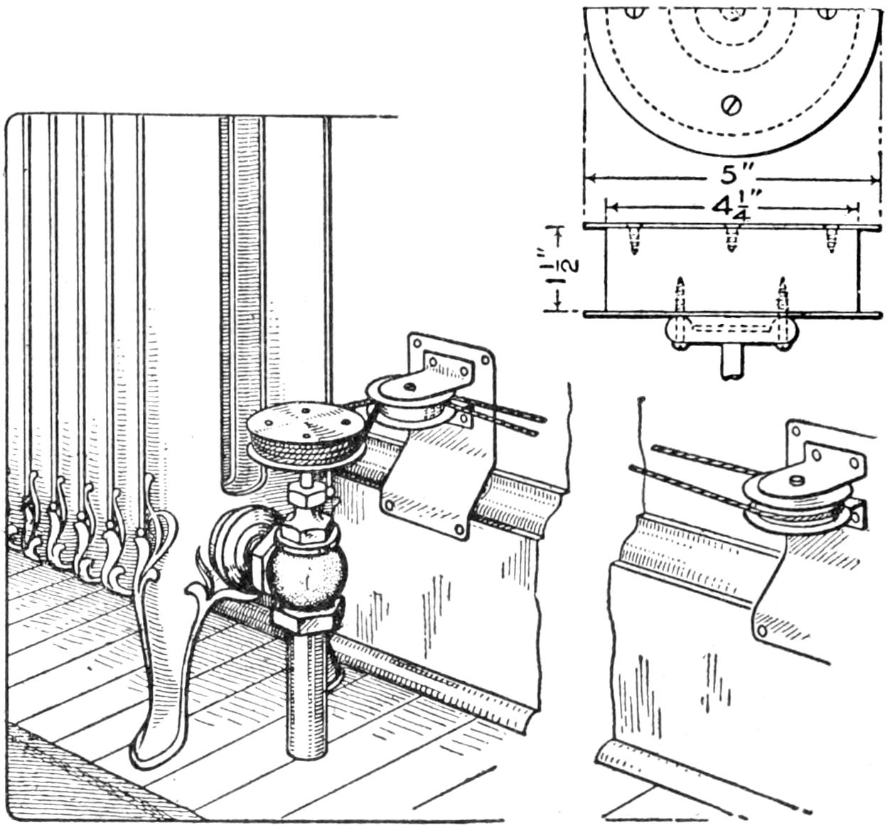
Draw on the Proper Cord to Open or Close the Valve
The construction of the pulley attached to the top of the valve wheel is shown in the small sketch at the right. It is built up of a center section of wood and flanges of sheet metal, fastened with screws. The pulleys attached to the wall are built in the same way, but are smaller. Any size that is convenient may be used for the larger as well as the smaller pulleys, but the larger pulley must be small enough so that it will not rub against the end of the radiator.
The cord is wound around the pulley at the valve handle, several times, like the steering cord on a motorboat. This gives a positive grip on the pulley. The cord may be conducted directly from the large pulley to the nearer small pulley, the other small one being omitted.
To operate the device draw on the proper cord to open and close the valve. It would be well to mark the cords with tabs so that they may be readily distinguished.—Contributed by P. D. Norton, Chicago, Ill.
[260]
An ornament for the automobile-radiator cap that attracted a great deal of attention at night was made by attaching two incandescent lamps to the blades of a small propeller, which is whirled around by the wind. By using the shaft on which the wheels of a roller skate revolve, ball bearings were provided. One end of this shaft is held rigid in a block of wood.
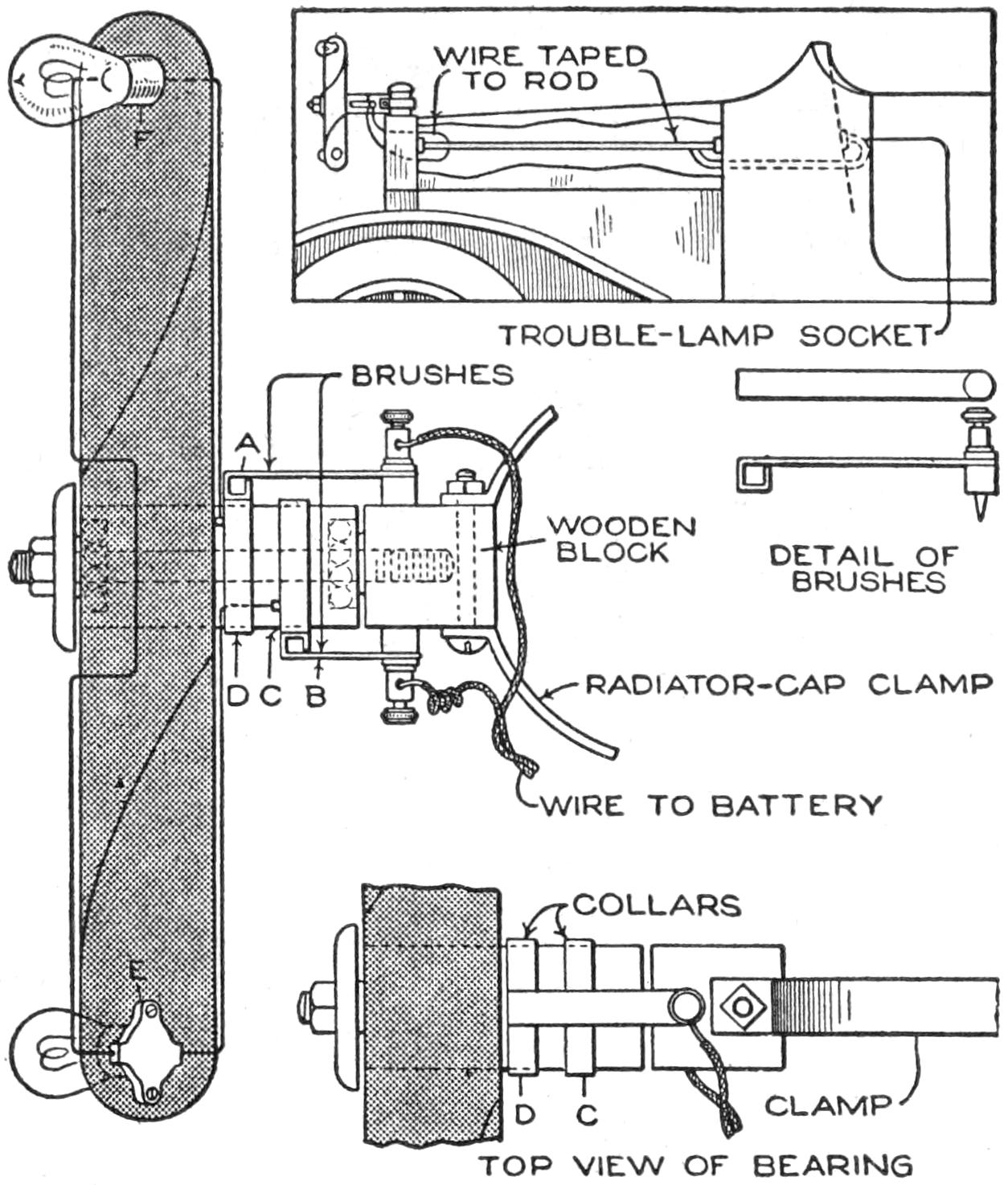
Homemade Ornament for an Automobile Radiator Revolves with the Bulbs Lighted, Attracting Attention
The wires which lead from the propeller are run under the hood, and attached to the socket for the trouble lamp. They are taped to the rod that braces the radiator, to avoid a short circuit, and then out from under the hood at the radiator cap, and connected to the brushes A and B. The incandescent electric-light bulbs are attached to the ends of the propeller blades and connected in series. The wire is run from one side of the socket E to the collar C, and soldered to the latter. The wire from the other side of the socket is connected to the other lamp F. The other wire from this lamp socket at F is soldered to the other collar D. The brushes are made by bending a strip of copper into the shape shown in the detail, and fastening it to the wooden block by means of screw binding posts, soldered to the strips.—F. Lloyd Adams, Jersey City, N. J.
Few persons realize what an intense heat may be developed when the globe of an ordinary incandescent lamp is tightly inclosed, largely eliminating the loss of heat. When the lamp is inclosed, the temperature will increase until the rate of radiation is equal to that at which the heat is generated. A good reflector is a poor radiator, hence, when the metal wall surrounding the lamp is bright and shiny, both inside and out, the heat is reflected inward.
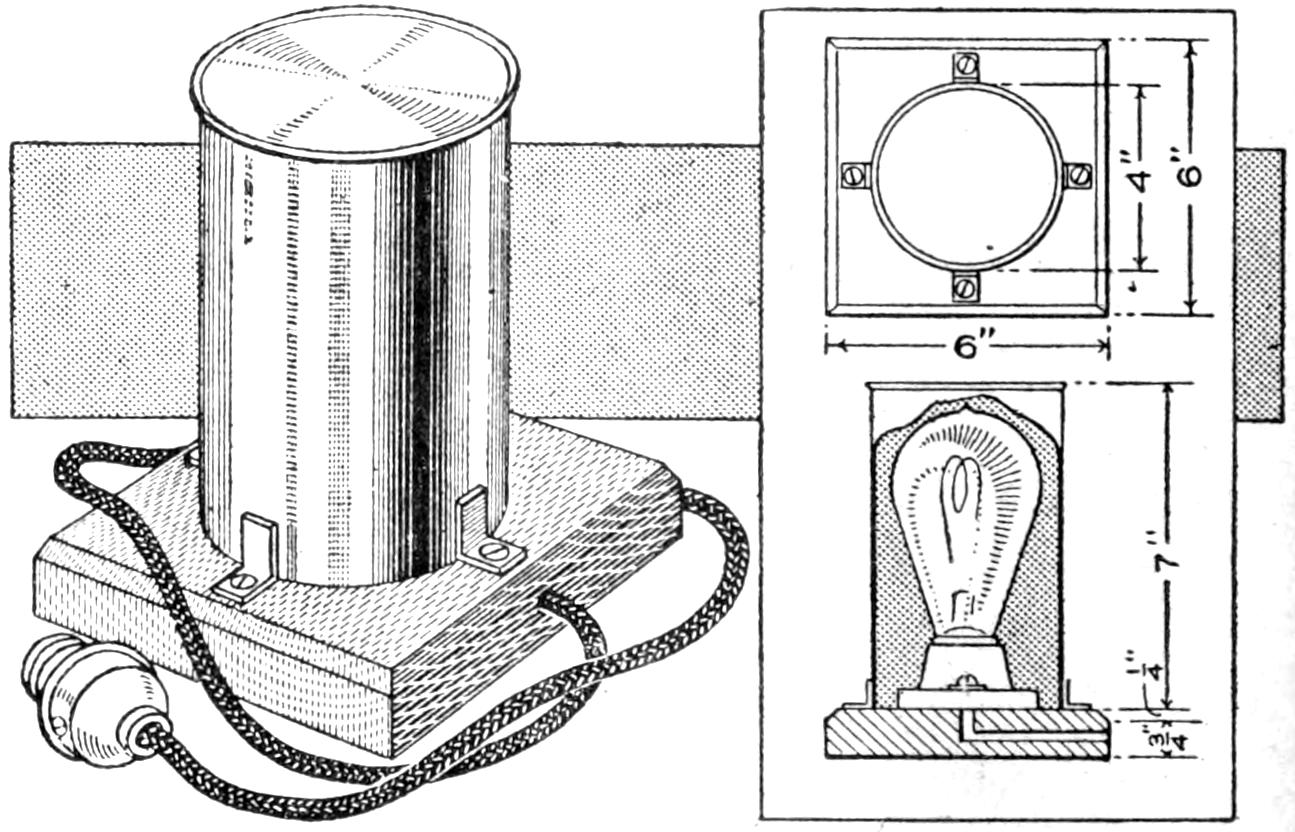
A Handy Electric Stove can be Made at an Outlay of 50 Cents
To make a small stove that will keep liquids warm, melt paraffin, dissolve glue, etc., procure an ordinary 16-cp. carbon lamp, a porcelain receptacle, and a bright, clean tin can, about 4 in. in diameter and 7 in. long. Thoroughly blacken the bottom on the inside, and then solder on four small brackets, cut from sheet brass or copper, so that the can may be held down firmly, when inverted on the base. The latter should preferably be made of hard wood, with the upper edges beveled, as shown. Next bore the hole for the wire or flexible cord. Fasten down the porcelain receptacle, connect the wiring, screw in the globe, and screw down the tin can; the stove is then ready for operation.—John D. Adams, Phoenix, Ariz.
[261]
Woven Reed Furniture
By CHARLES M. MILLER
A Variety of Small Stools and
Foot Rests
[The various materials referred to in this article by number or size were described in detail in an article on “A Reed Basket,” in the Boy Mechanic, Book 2, page 257.]
Footstools of reed are preferable, in the home, to those made of other materials, because of their light weight, rounded edges, and comfortable, yielding tops. Reed, rattan, and similar material, used in their construction, withstand hard wear, and will not easily mar floors or furniture, a feature not to be overlooked, especially since the footstool is a favorite seat or play table of children. Several types of stools and foot rests are shown in the illustration. A stool having a framework of dowels, covered with reed, and utilizing the frame to produce a paneled effect, is shown in Fig. 3. The upper dowel of the framework is covered and woven over with the top, in the somewhat lighter stool shown in Fig. 8; the legs are braced at the ends with reed, arched and covered with winding reed. The stool shown in Fig. 11 is designed with rounded lines, the bracing dowels being set low, and a panel of openwork woven into the sides. Figure 15 shows a foot rest, the framework of which is steamed and bent, and the top slanted to provide a more comfortable rest for the feet. It is strongly braced, paneled on the sides with winding reed, and ornamented with openwork scrolls. The details of the construction of the frames and the method of weaving the reed are shown in the other sketches.
Dowels, ³⁄₄ in. in diameter, are used for the main framework of all of the stools shown. The dimensions of the various stools may be made to suit individual taste, those suggested in each instance having been found satisfactory. A good size for the stool shown in Fig. 3 is: height, 9 in.; width, 11 in.; length, 15 in. The lower of the horizontal dowels should be set at least one-third the height of the leg from the top. The braces are notched at their ends to fit the curve of the legs, and finishing nails are driven into them through the legs. The corner joints are further reinforced by a binding of reed, placed over them. The holes for the spokes are bored through the braces before the construction is nailed together. They should be bored about 1¹⁄₄ in. apart, spaced uniformly, according to the length and width of the stool. The tops of the legs should project about ¹⁄₁₆ in. above the upper braces, so as to produce a level surface when the winding reed is applied.
The upper end of the legs must first be covered with winding reed, as shown in Fig. 2. Tack a strip of the reed on; then add successive pieces, as shown, until the end is covered. The joint of the leg and the lower brace must be reinforced, as shown in Fig. 2, by tacking winding reed over it horizontally. The braces must then be wound with winding reed, the spokes being inserted later. In winding the reed on the braces, tack one end of it to the brace at the left of a leg; then begin the winding on the brace to the right of the leg, and as each hole is encountered mark with pencil on the reed, so that if any of the holes are covered[262] they may be found easily, when inserting the spokes. The marks should be made on the lower side.
The spokes extend from the lower edge of the bottom rail on one side to the lower edge of the corresponding rail or brace on the opposite side. Short spokes are fitted between the upper and lower rails at the ends of the stool. The top is woven complete before the sides are woven, the pairing weave being used. In this method two strands of reed are handled together, the first passing behind one spoke, and being below the second strand, and then passing in front of the next spoke, and being above the second strand, etc. This weave is shown in detail in Fig. 9, illustrating an article on “Taborets and Small Tables for the Summer Veranda,” page 155, July, 1916. The weaving of the top includes the covering of the upper rails at the ends of the stool, which are wound in as spokes, the reed passing around them and being directed back in the opposite direction.
The weaving for the sides is carried around the stool continuously, passing around the legs. One of the strands in the pairing weave passes behind the leg, and the other must be wound around it an extra turn, to cover up the space otherwise exposed. The reed is wound around the legs to the lower end, the strand being tacked at the inner side of the leg.
The framework for the second type of stool is shown in Fig. 6. The two side rails are fixed into place by the same method used in making the first stool, and the frame is braced on the ends by sections of No. 12 or No. 14 reed. These are fitted into place and covered in the winding. The braces should be fitted to the curve of the leg, and nailed into place with small finishing nails. The ends where the braces join the legs and rails should be whittled down to a long, thin wedge, so that they may be bound in securely by the reed that is wound around the legs, as shown in Fig. 4.
The spokes in this model, as shown in Fig. 6, do not pass through the upper rails, but extend from one lower rail over the upper rails and to the lower rail on the opposite side. This makes it necessary that the upper rails be set slightly below and in from the top and outer edges of the legs. The lower rails should then be set in so as to be uniform with the upper ones.
The lower rails and the end braces are wound by the method used for the rails in the first stool. The tops of the legs are finished differently, however, as shown in Figs. 4 and 5. The weaving is begun at the lower rail, and proceeds until the side panel is filled to the under edge of the upper rail. The weavers cannot then be returned at the corner, and are cut off to extend 2 in. beyond the leg. Their ends are thinned out, and then brought around the corner against the upper rail on the end, as shown in Fig. 5. Alternately they are turned down on the leg and against the end rail, producing a covering for the corner. The strands of the top are woven over the thinned-out ends, and bound over the joint of the braces with the upper rail. The corners may be beaten gently with a block of wood to smooth them, and to bring the weavers firmly together. The weavers pass twice around the legs, as each strand is brought to the leg, as shown in Figs. 5 and 7. It will be found convenient to place the spokes in only one lower rail, as in Fig. 6, while weaving the first side panel, and the top. As the work proceeds the spokes are bound down to the upper end rails, and when the middle of the second side panel is reached, they are trimmed off and fitted into their holes, on that side.
The third stool differs fundamentally from the preceding ones in that the framework is curved at the upper ends, and the weaving of the top is carried down over the ends. The framework is shown in detail, in Fig. 9. Ash dowels, ³⁄₄ in. in diameter, are used for the framework, and the rails are notched into the main sections, and nailed, as were those in the preceding stools. The length of the curved dowels must be determined carefully, and it is desirable to have the stock longer than is necessary for the finished pieces, so that inaccuracies in bending may be allowed for properly. The distance between the legs should be such that a space of ¹⁄₂ in. is provided between the legs and the first hole for the side spokes, and the intervening spokes should be placed 1 in. apart. A satisfactory size is to make the stool 6 in. high, the end rails 8 in., and the side rails 13 inches.
[263]
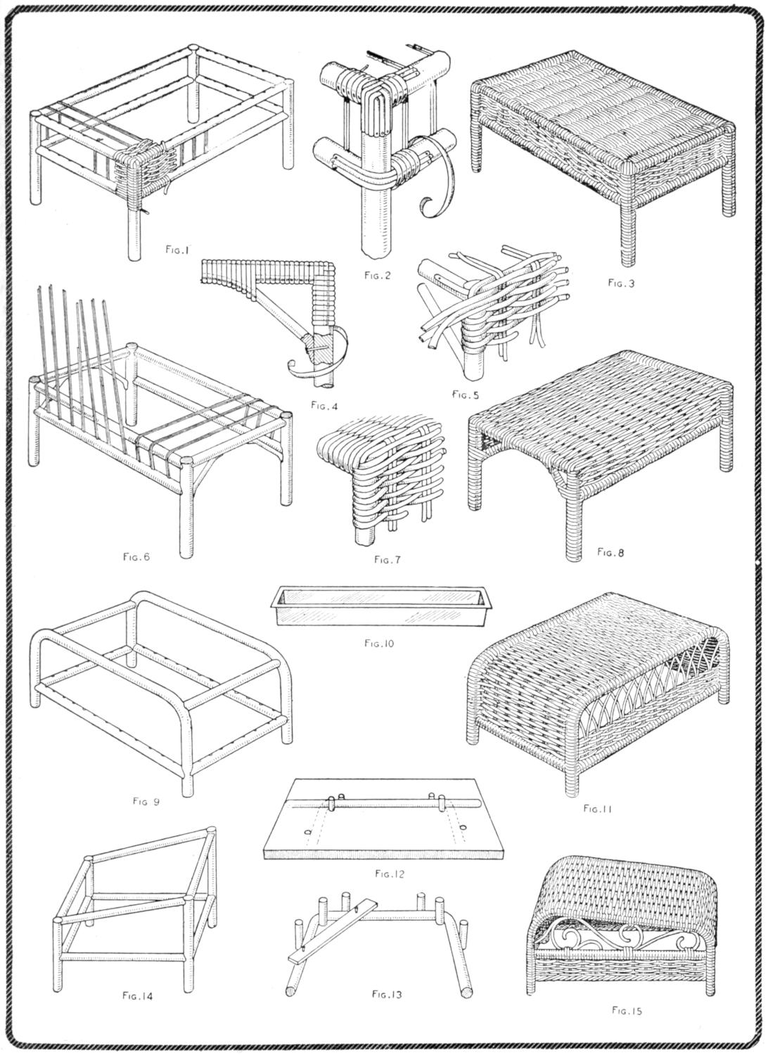
| Fig. 1 | Fig. 2 | Fig. 3 | |
| Fig. 4 | Fig. 5 | ||
| Fig. 6 | Fig. 7 | Fig. 8 | |
| Fig. 10 | |||
| Fig. 9 | Fig. 11 | ||
| Fig. 14 | Fig. 12 | Fig. 15 | |
| Fig. 13 | |||
The Making of Stools in Woven Reed Affords the Craftworker an Excellent Opportunity to Produce Constructions, for Home Use, or as Gifts, That Have Originality and a Personal Element. The Frameworks for Four Typical Stools and Foot Rests are Shown at the Left, and the Completed Objects at the Right. Figure 14 Shows a Variation Adaptable to the Methods of Weaving Shown in Other Models
[264]
The method of bending the dowels is shown in Figs. 12 and 13. They must be soaked in hot water or steamed, and clamped around the form as indicated, being left to dry. A pipe fitted over the ends of the dowels, to give leverage, will aid in bending them. The form is made by fitting pegs, suitably spaced, into a board, ⁷⁄₈ in. or more in thickness. The curved pieces may be braced temporarily, as shown, and removed from the form when partly dried, so that it can be used quickly for the second piece. The pegs must be set close enough together so that the curve at the upper ends of the legs will not be too large, making the legs appear short. Care must be taken in bending this short curve, as the dowels are likely to break if the curve is quite abrupt. By setting the pegs solidly and making them long enough, two pieces of dowel rod may be curved in the form at the same time, and permitted to dry. A convenient tray of galvanized iron, for use in heating water for the moistening of the dowels, is shown in Fig. 10. It is 28 in. long, but may be made shorter if the points at which curves are to be made are moistened separately. A wash boiler, or any other suitable vessel, may be used for heating the water and dipping the dowels into it. After being shaped, the pieces are trimmed off to the proper height on the leg portions. Holes for the spokes are then bored through the lower and side rails, and they are notched and nailed to the legs.
The cross rails of the framework, shown in Fig. 9, are fixed into place by the method used in the previous models. The lower rails should be set about 2 in. from the floor, and are bored for double spokes. The rails are set with their outer edges ¹⁄₈ in. in from the edges of the legs, so that the weaving will be flush with the surface of the legs, rather than project slightly beyond it. The spokes for the ends and seat, or top, pass from one lower rail on one end to the corresponding rail on the other end, and are supported on the upper end rails. There are no corners to be fitted with the winding reed in this model, as the windings continue over the curves at the ends and down over the latter, by the same method of weaving as used in the top. The weaving is begun at the lower rails, and passes completely around the sides and ends of the stool, until about 1¹⁄₂ in. has been covered, up from the lower rails. The ends only are then covered, the strands of reed passing around the curved portion of the upper rails, and around the dowels forming the support for the top, in weaving back and forth.
The ornamental weaving at the sides of the stool is produced by spreading out the double spokes and conducting them to the proper holes in the upper rails. Several types of design may be made by crossing the spokes in various ways before setting them into the holes in the rails. The short spokes in the sides are permitted to remain with their upper ends free and longer than necessary while the 1¹⁄₂-in. lower section is woven. They must be cut carefully to the size necessary to form the desired design, and the ends glued into the holes.
The stool shown in Fig. 15 is designed as a foot rest, with a slanting top. It is similar in general construction to that shown in Figs. 9 and 11, the framework being made of dowels, bent to the shape indicated by means of a form. The top and ends are woven in the manner described for the previous model. A point of difference to be noted is the bracing by means of a woven panel below the side rails, as shown in Fig. 15. This feature may be carried around the ends also, or the ends may be braced to the lower side panel by the method of bracing shown[265] in Fig. 4. The rails around the stool are all on the same level. The double spokes for the top are fixed into the end rails, the spokes for the side panels into the side rails, and the smaller dowel placed at the lower edge of the side panels, as a support for the twisted weaving shown. The weaving of the top and the panels is by the method used in the previous model. The scrolls fitted into the open portions of the sides are tacked into place, and the strands of weaving reed carried over them, where the curves touch the upper and lower rails. A variety of designs may be worked out for the openwork. The scrolls are made of No. 6 or No. 8 reed, and should be formed on a base, as in Fig. 12, brads being used to hold them in shape until dry.
Another type of foot rest with a slanting top is shown in Fig. 14. The framework is built up of dowels, straight sections only being used. The joints are fastened by the method used in the first and second models described. The method of covering the frame is essentially the same as for the stool shown in Fig. 15, or an adaptation of that used in Fig. 11 may also be applied. Where facilities for steaming or moistening the dowels are not to be had conveniently, this type of construction will be found satisfactory, the designs being limited to straight lines, however. The method of covering the framework used in Fig. 3 is also available for the framework shown in Fig. 4, and the corners may be finished as shown in Fig. 2. Numerous variations and combinations of the types shown may be worked out readily after one has become reasonably familiar with the possibilities of woven-reed construction.
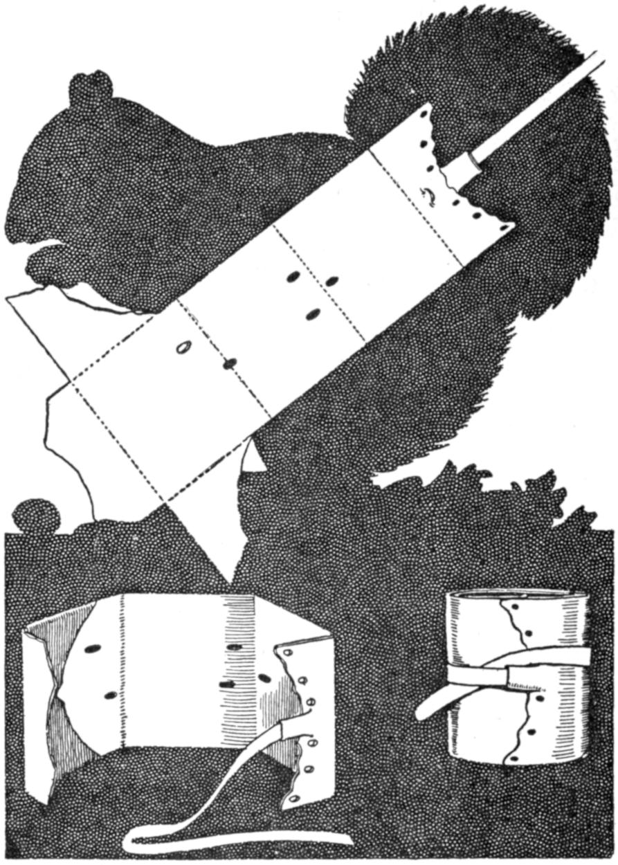
Bill Fold Fashioned from a Squirrel Skin as a Souvenir of a Hunting Trip
As a souvenir of the “days afield” my brother fashioned a quaint bill fold out of a squirrel skin, which, by the way, is a skin of remarkable toughness, After tanning the skin and removing the hair, it was cut as shown, the skin of the forelegs being used as fold-overs. The piece of tape took the place of the tail. The shot holes through the skin added the requisite touch of realism, recalling a day with the gun.—James M. Kane, Doylestown, Pa.
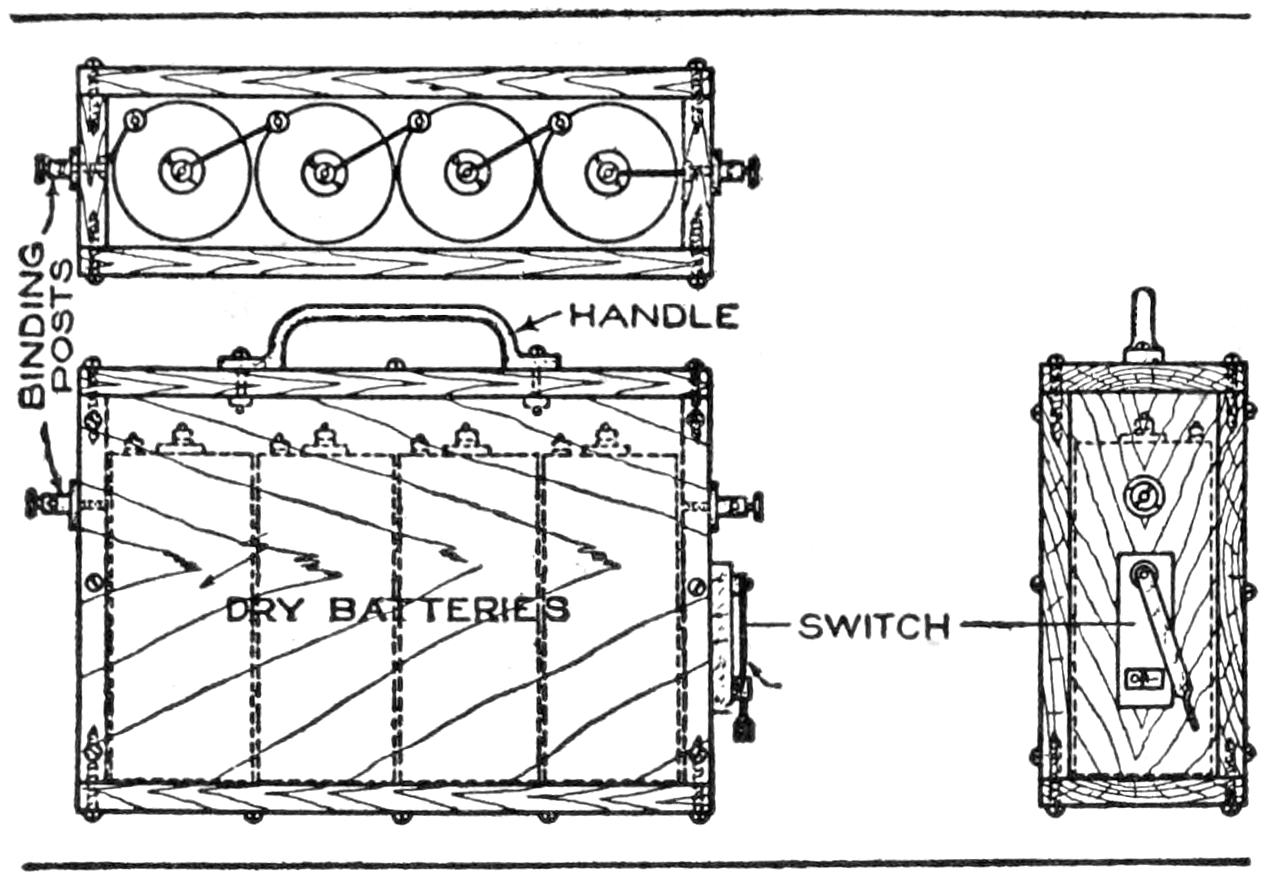
Batteries Protected by a Waterproof Case will Give Longer and More Efficient Service
Dry batteries that are sealed in a tight, waterproof case will last much longer than those exposed to dampness, especially in marine practice. A box, like that shown in the sketch, will afford excellent protection and add materially to the life and efficiency of batteries. It is constructed of ¹⁄₂-in. cypress, or oak, of a length and width depending upon the capacity in number of cells desired. The inside dimensions should be such that the cells are firmly fitted. It should be put together with screws and marine, or any other waterproof, glue. The batteries should be placed in the case and connected. Molten paraffin wax should then be poured over and under the cells. Do not get the wax too hot, but heated only to the melting point. Binding[266] posts and a single-blade switch should be placed on the case and connected up. Screw on the cover, after painting the top edges with the glue. Give the case a good coat of varnish and paint, and fit with a carrying handle. This makes a neat and handy battery outfit that is thoroughly waterproof. The case can be refilled by cutting out the wax and removing the old cells.—B. F. Dashiell, Baltimore, Md.
Accurately formed ratchet wheels of small size may be made without special appliances in a lathe. A triangular file and a simple gauge, made of a piece of hardened steel, are the only tools required, as shown in the illustration.
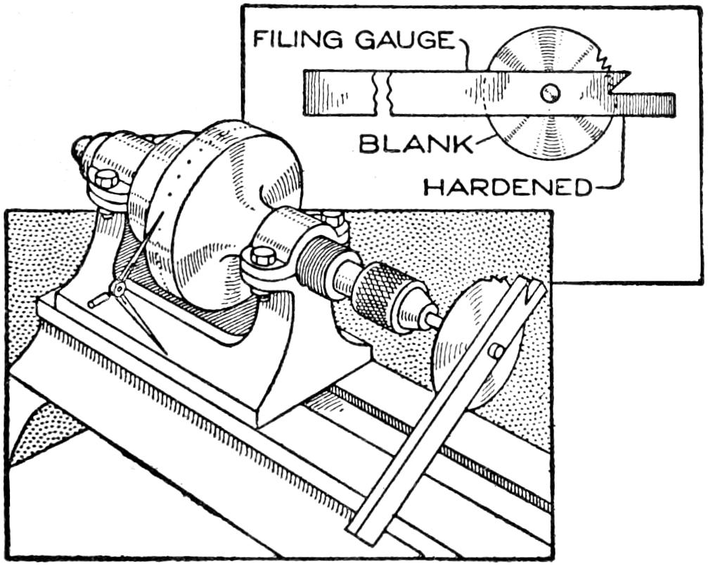
Ratchet Wheels may be Cut Accurately with a File, Using a Hardened-Steel Gauge as a Guide
The lathe is prepared as an index for the ratchet wheels by dividing the face of one of the steps, preferably the largest of the cone pulley. A center punch may be used in marking the graduations slightly, and another point should be marked in the headstock base, from which dividers are used to gauge the movement of the spindle. The dividers should be set, when the work is begun so that one point rests in the punch mark on the headstock and the other in one of the marks on the pulley. The bearings should be tightened so that the work will not shift easily. The blank to be cut is supported on an arbor provided with a shoulder, and is held in place by a small machine screw threaded into the end of the arbor.
The teeth are cut by filing them with the gauge as a guide. If the spindle is turned carefully so that the dividers register the graduations precisely, the ratchet wheel will be cut accurately. By first roughing out the teeth and then refiling them with a fine file, a more smoothly finished surface will result. Other forms of teeth might also be made if a properly shaped gauge is provided.—Charles F. Merrill, Hopedale, Mass.
Lifting a hatbox down from a high shelf, only to find that the desired hat is not among the several hats contained therein, is annoying. If the hat shelves of the clothes closet are provided with boxes that open on the front, the hats may be removed easily without taking the boxes from the shelves. Rectangular boxes are used for making the front-opening containers by cutting the side corners of the front, and using the front lower edge as a hinge. The top, or cover, is placed over the box, holding the hinged front in place when closed. These boxes have been found to afford ample protection and are convenient.—D. J. Hough, Toledo, Ohio.
Screws holding light fittings in a bathroom were found to be driven into the plaster between laths and became loosened. No strain was placed upon them, and as it was desired to replace the screws in the same holes, the following[267] method was employed: A cotton string was wrapped around the threads of the screw, and the screw then dipped into plaster of Paris until sufficient of this adhered to it to fill the hole in the wall and to permit some of it to be forced behind the plaster. When the plugs thus formed were dry, they resisted a considerable pressure, by reason of the enlarged portions behind the plaster.—H. A. Trester, Milwaukee, Wis.
After trying several devices for keeping my fishhooks, I hit upon my present method, which has been found satisfactory. The materials used are: a ¹⁄₂-lb. baking-powder tin; two disks, 2 in. in diameter and ¹⁄₄ in. thick, sawed from a convenient limb; a twig, 4 in. long, somewhat smaller than a lead pencil, made smooth and straight; enough cork stoppers, about ³⁄₄ in. in diameter at the small end, to make 3¹⁄₂ in. in length, and a few drops of cold glue.
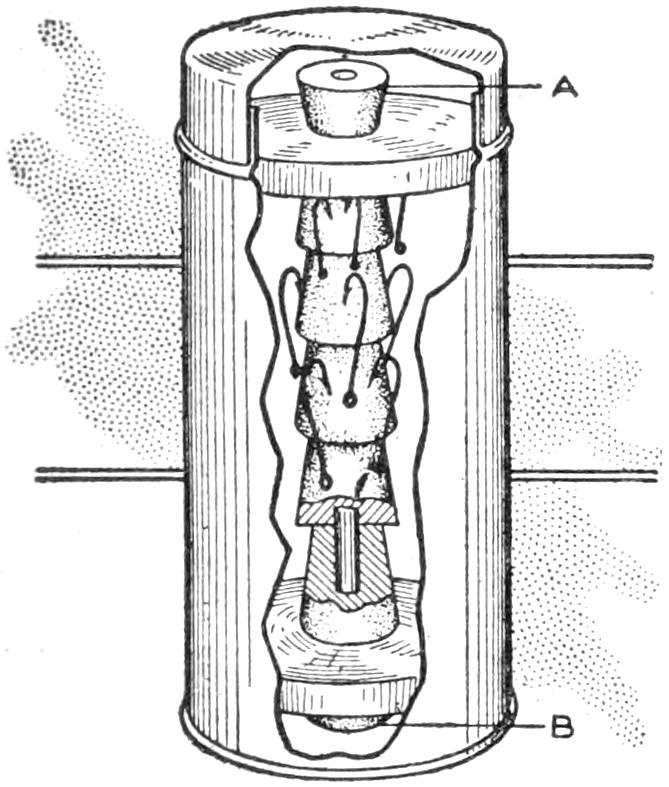
Drill a hole lengthwise through the through the stoppers and through the center of each disk, just large enough to allow the twig to pass through closely. Cut from the small ends of two of the stoppers a piece, ¹⁄₄ in. long, for pieces A and B. Pass the twig through the long stoppers and the disks; the pieces A and B should then be glued to the ends of the twigs projecting beyond the disks, to fasten the hook holder together, and to be used for handles by which it may be lifted from the box. If the hooks are dry when they are stuck into the corks which form the center, they will keep in good condition indefinitely, and their points will never be dulled by coming in contact with the tin sides of the box or with each other.—C. A. King, East Kingston, N. H.
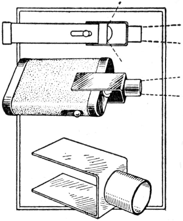
It is often desirable to concentrate the rays from a pocket flash lamp on a limited area rather than spreading them, as is the case with many lamps of this type. The addition of a hood, which may be slipped over the lens, as shown in the illustration, concentrates the light in this manner. A strip of sheet brass, about ¹⁄₃₂ in. thick, 4 in. long, and ³⁄₄ in. wide, was drilled at the center, forming an opening of the same diameter as the lens. A brass tube was soldered to fit over the hole. The ends of the strip were bent back at right angles, to hold the device firmly against the sides of the flash lamp. The lamp is used in the ordinary fashion, and the clip may be removed quickly when not needed. It may be plated or finished to suit the metal parts of the lamp.—Ralph W. Tillotson, Erie, Pa.
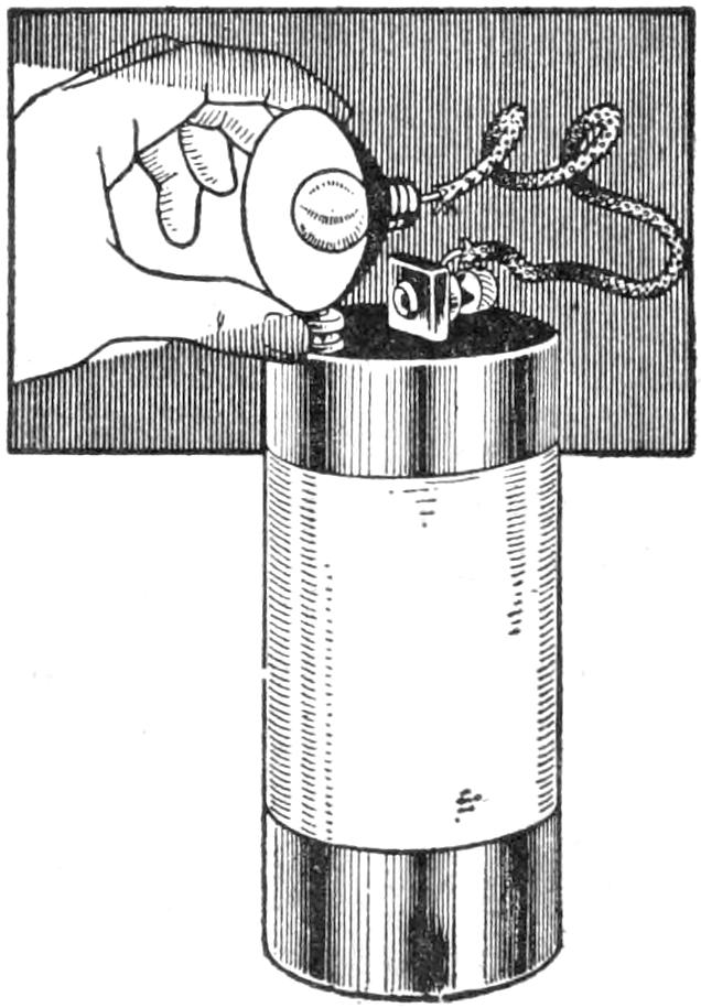
Tests of batteries for telephones, doorbells, and similar appliances, may be made by the use of a lamp from a pocket flash light. Remove the reflector and lamp and connect them with the poles of each cell to be tested, as shown in the sketch. The glow of the lamp is proportional to the amount of life in the cell. Very often but one dead cell will be found to cause trouble. By testing carefully the good cells may be retained and new ones substituted for those worn out.
[268]
When a daylight developing tank is used, a dark room is needed only for loading the plate holders and for transferring exposed plates to the tank. These operations may be performed satisfactorily in darkness, using a large box with holes made in the side to admit the hands, as shown in the sketch. The box may be made of light wood or stout cardboard. The sleeves fitted to the openings are provided with elastic bands to insure that no light creeps in at the edges. The holders, plates, and sponge should be arranged conveniently in the box before beginning operations.
A Dark Room Is Unnecessary for the Loading of Plates When the Device Shown is Used
The box must be made light-proof by lining it with black cloth if necessary. If any difficulty is experienced in identifying the film side of the plates they may be marked with minute tabs at the corner on the film side, or identified by moistening the finger tip on the sponge and testing for a slight stickiness of the film side at the extreme corner. A red window might be fitted into the box, but the device has been found satisfactory without it.—Contributed by H. J. Gray, Lewes, Sussex, England.
¶New brooms should be soaked in strong, hot salt water. This toughens the bristles and makes them last much longer.
Old inner tubes of bicycles, or other vehicles, may be cut into rubber bands of various widths which will be found to give good service. The tubes should be laid flat on a hard piece of board, or a piece of sheet zinc, and the bands cut off one at a time with a sharp knife held against a straightedge. In cutting them on wood, it is best to use a close-grained stock and to cut across the grain of the wood.
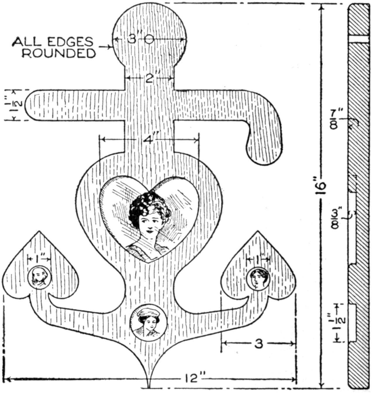
The Center Panel is Reserved for the Sailor’s Sweetheart, and in the Others Pictures of Relatives are Placed
The boys on United States battleships are fond of making trinkets and souvenirs to be sent home, and the sailors’ sweetheart picture frame shown in the sketch is a favorite. Speaking from experience, I know that many “landlubbers” will be interested in this novelty, although coming from a man-of-war makes it more interesting. I have been there and, therefore, I know. The place of honor in the center is of course reserved for the lady. The smaller picture openings may be filled with penny pictures of father and mother, or other relatives.—Contributed by Charles Rorer, Bridgeport, Connecticut.
[269]
Woven Reed Furniture
By CHARLES M. MILLER
Taborets and Small Tables for the
Summer Veranda
[The various materials referred to in this article by number or size were described in detail in an article on “A Reed Basket,” in the Boy Mechanic, Book 2, page 257.]
Utility and ready portability are well recognized features of woven-reed furniture, but the qualities which make it especially attractive for summer use in the open air, or on the veranda, are its inviting comfort and graceful lines. While furniture of this type arranged in suites makes a particularly harmonious showing, individual pieces may be used in combination with other furniture, lending a touch of variety. Small tables or taborets, of light weight and simple design, may be made by the novice, and may be adapted to a variety of uses. Footstools, jardinière stands, sewing tables, yard tables, and smoking stands are some of the possibilities. Three representative types are shown in Figs. 1 to 3, and the general method of construction as well as the details of the weaving are also illustrated.
A serviceable taboret or stand is illustrated in Fig. 1. It is 18 in. high, and 17 in. in diameter on the top. The sides are 9 in. wide at the top and 14 in. at the bottom.
The framework for the top of the stand consists of a disk of wood, 16 in. in diameter, with a similar one, 14 in. in diameter, directly underneath, the edge being set under 1 in. all around. Four legs of 1-in. doweling support it, and two cross braces of doweling are placed between diagonally opposite corner posts, behind the woven portions of the side. The grain of the wood in the upper disk should run at right angles to that of the lower, to prevent warping, and the disks should be fastened together with nails or screws. Avoid putting them into the lower disk, where the legs are to be fixed.
To locate the position for the legs, draw a diameter on the under side of the top, as at A, Fig. 4, and 4 in. on either side of it draw parallel lines B and C. Draw another diameter, D, at right angles to A, and draw the parallel lines E and F 4 in. from the diameter D. Where the four outside lines intersect will be the centers of the holes for the legs. These holes are not bored perpendicularly, but are slanted to conform to the slant of the leg. A template should be used in guiding the bit, as shown at G, Fig. 4. It may be constructed of wood, 3 in. wide and 5 in. long, Fig. 5. Place the gauge just outside the edge of the hole to be bored. Nail it to the board lightly on the diagonal, as shown, and guide the bit against it.
Before the legs are fixed into place finally, the holes for the spokes of the side should be bored. The parallel lines of Fig. 4 now serve another purpose, that of giving the location of the spokes. Place one spoke ¹⁄₂ in. from each leg, and the others 1 in. apart. The legs are utilized as spokes in the weaving. The spokes should be double, and the extra spokes may be inserted beside the original ones, after the weaving has progressed a few rounds. Number 5 reed should be used for the spokes and No. 4 reed for[270] the weavers, which are woven back and forth around the spokes.
Drive the legs into their sockets, applying glue, and pin them with nails, as at H, Fig. 4. Tack strips on the bottoms of two pairs of legs and then fasten two strips to brace them, as shown in Fig. 6. The strips should be put on and the distance between the legs spaced before the glue sets.
It is best to weave the sides before beginning the top, so as to prevent rubbing the woven top while weaving the sides, with the stand inverted. The side spokes should be 2 ft. long and should be set into the top 1 in., with glue. Turn the top of the stand down on a table, and begin the weaving at the under side of the top. Single weaving is used for the sides, every other round passing twice around the legs.
There being four sides in the construction, there will be an even number of spokes, even though there should be an odd number to each side. The weaving would thus repeat itself, in going behind and before the same spoke each time. This is not desirable in this construction, and a change should be made each round. To do this, go over two spokes, instead of one, at the finish of a round. Such a “skip” is an Indian method, and forms a design that may be carried in slanting lines back and forth down the side of the stand. It is best to confine these “skips” to one side. Another way to overcome the repeat, as the weaving in and out around the same spokes in two successive layers is called, is to insert an extra spoke on one side, thus making an odd number of spokes around the stand. It is necessary then to conform the design of the open work for this side to the number of spokes. The design for the open work shown in Fig. 2 will be used for the stand illustrated in Fig. 1, and to be described in detail. The first of the two methods of overcoming the “repeat” will be used.
Insert the extra reed for doubling the spokes, after a few rounds have been woven adjoining the top. The method of weaving from the corner post and the making of the open design are shown in Figs. 7 and 8. The method of “pairing” for winding the reed in and out of the spokes, is shown in Figs. 9 and 10. The rear weaver of the pair of strands is thrown over the forward weaver, back of the next spoke and out. The fore weaver then becomes the rear one, and is thrown in like manner. This process is repeated in order to make the complete rounds. Figure 9 shows the weaving from the side, and Fig. 10 is a view looking down on top of the spokes and the edge of the weaving, shown in section. Pairing gives a continuous rope twist to the two weavers, and an even or odd number of spokes is equally suitable.
For the open designs of Fig. 2, one or more of which may be placed in the side of the stand, the center spokes are left free, as shown in Fig. 7. Before turning the first weaver back for the open work, as at M, start a short weaver N about two spokes back from the opening, and pair it with the regular weaver across the opening, and two spokes beyond. In turning back on the spokes, the single weaver goes twice around the spokes, as shown by the intermediate layers O. This is a short bend and the weavers must be very soft. Use short ones and wet them frequently with a sponge. A sectional view of the weaving at the opening is shown in Fig. 8, as it joins with the weaving around the corner posts. At K, the weaver turns back on a double thickness of reed, and at L, a short spoke is set back of the other two, and the weaver is wound around the three, thus lessening the abruptness of the winding. The latter method is the better. At the horizontal center of the opening, two rounds continue across the opening and around the stand. Pair a short piece of reed across at the finish of the openings, as was done at the lower end at N, Fig. 7.
After weaving to within 5 in. of the bottom of the legs, cut off the extra member of the double spokes, and soak the ends of the remaining spokes in water. Braid them into the border finish, as shown in Fig. 1. The corner posts serve as spoke spaces, and the spokes nearest them are wound around the bottom ends of the legs. Short spokes may be inserted beside the posts and wound around them if the ends of the spokes are not long enough for this purpose.
[271]
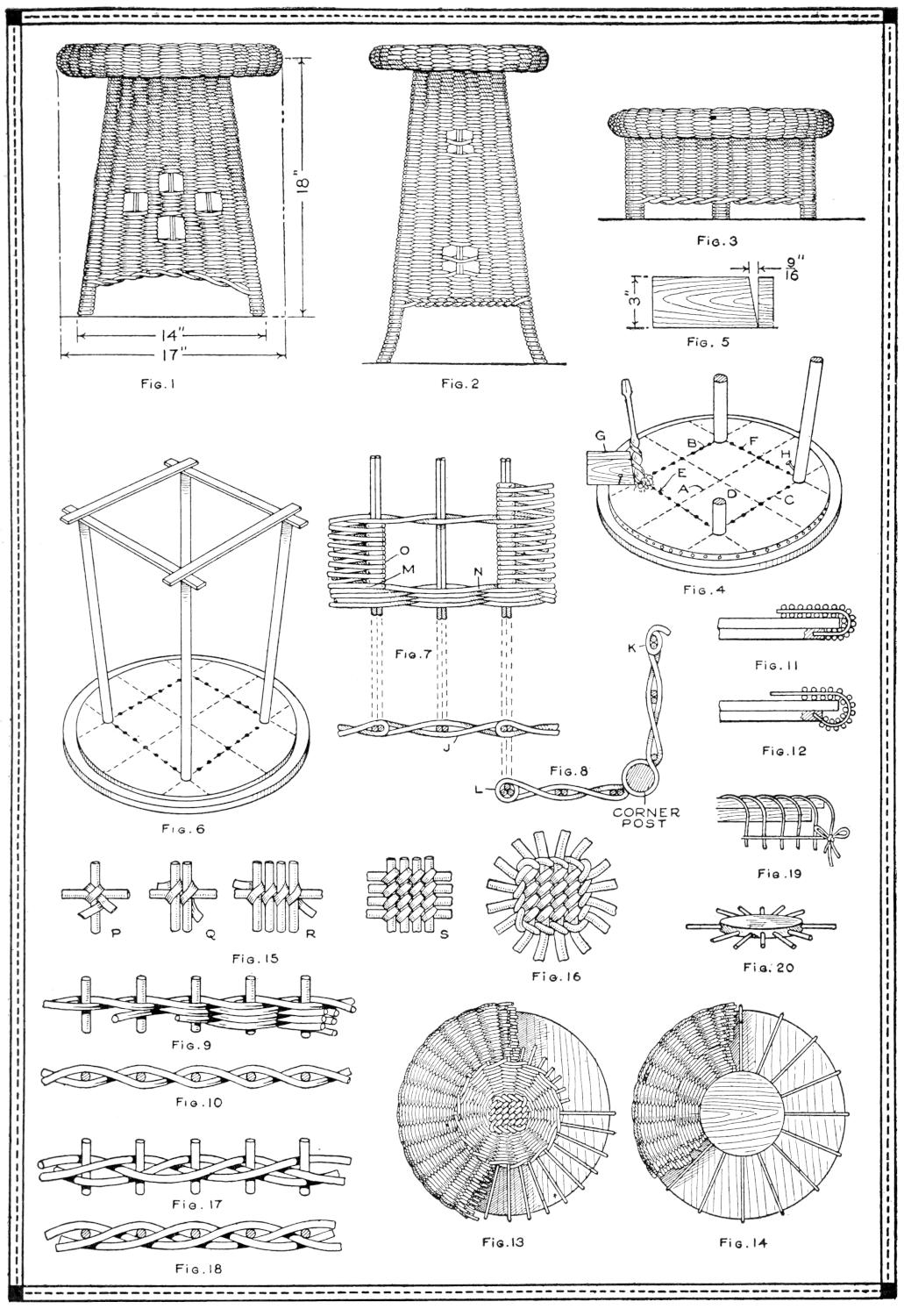
| Fig. 1 | Fig. 2 | Fig. 3 | ||
| Fig. 5 | ||||
| Fig. 6 | Fig. 7 | Fig. 4 | ||
| Fig. 11 | ||||
| Fig. 12 | ||||
| Fig. 8 | Fig. 19 | |||
| Fig. 15 | Fig. 16 | Fig. 20 | ||
| Fig. 9 | Fig. 13 | Fig. 14 | ||
| Fig. 10 | ||||
| Fig. 17 | ||||
| Fig. 18 | ||||
Taborets, of Light Weight and Simple Design, may be Made by the Novice and Adapted to a Variety of Uses in the Home. They Are Particularly Attractive for the Summer Veranda. Sewing Tables, Jardinière Stands, Taborets, Footstools, Card Tables, and Smoking Stands Are Some of the Possibilities. A Taboret, or Small Stand, is Illustrated in Fig. 1, and the Details of Its Construction are Also Shown. The Tall Stand illustrated in Fig. 2 Involves the Same General Principles of Construction, Modified to Suit the Framework. The Footstool Shown in Fig. 3 Is Typical of Stands Having Vertical Sides
[272]
The top may be made next. Holes are bored horizontally into the edge of the under disk, as shown in Figs. 4 and 11. In Fig. 12 the holes are shown bored into the edge on an angle. This method gives a thicker rolled edge to the top, although both methods are satisfactory. These holes must be bored before the work on the top is begun. There are two ways of beginning the weaving for the top. The radial spokes may cross each other in groups of four, the upper and lower courses being bound together with winding reed, as shown in Fig. 13, or a small maple disk may be used as a center from which the spokes radiate, as shown in Figs. 14 and 20. The center-disk method is not difficult, and is used extensively. The other type is novel, and also quite feasible.
The spokes for the method shown in Fig. 13 are bound together in the following manner: Place two spokes at right angles to each other and wind them with winding reed, the end of the latter beginning between the two spokes, as shown at P, Fig. 15. The perpendicular spoke is uppermost. Add a second perpendicular spoke and bind it into place, as at Q. Continue this process until four perpendicular spokes have been bound in as at R. Place a second horizontal reed into position and go over each vertical spoke with a separate winding, as in the first course. Continue until four horizontal spokes are bound in, and the end of the winding reed is looped around the last, as shown at S. The spokes should be of No. 5 reed, and 24 in. long.
Four groups of four spokes each will result by following out the process described. Separate the spokes by drawing the outer ones into the corner spaces. They should have the appearance of spokes in a wheel, as in Fig. 16. Use two weavers of No. 4 reed, in the pairing weave, as shown in Fig. 16, and in detail in Figs. 9 and 10. Continue the pairing weave until a center, 8 in. in diameter, is woven. Crowd up the weaving closely, for the appearance of the top will depend much on the first few rounds. Hold the center with the left hand, and manipulate the weavers until they are well seated in their proper places.
When a few rounds have been woven, nail the center securely to its place on the middle of the top. This will leave both hands free for the weaving. After a disk, 8 in. in diameter, has been woven, begin the triple weave illustrated in Figs. 17 and 18. As the triple weave is begun, add another spoke, 8 in. long, between each pair, all around the top, making 16 new and 16 original spokes. When two or three rounds are woven, the new spokes will become secure. Continue the triple weave to the edge of the top. Measure and cut the end of the spokes to uniform length. Curve the ends over the edge to see how much will be needed before cutting, allowing about ¹⁄₂ in. for insertion into the holes in the edge.
Wet the ends of the spokes with water until they are pliable enough for the curve. Bending and tying them down while wet and permitting them to dry in this position, as shown in Fig. 19, is desirable also. Weave down the curve of the roll and insert the ends of the spokes in their respective holes with glue. Then with the single, plain weave on the under side of the roll, weave well up to the ends of the spokes.
For the disk-center method of construction, as shown in Figs. 14 and 20, use ¹⁄₂-in. maple, and cut it 5 in. in diameter for the centerpiece. To locate holes on the edge of the disk draw a line ³⁄₁₆ in. from the upper edge and mark off spaces 1 in. apart, except four, which are made ¹⁵⁄₁₆ in. apart, to make a convenient division, practically uniform. Bore the holes ³⁄₄ in. deep. Number 5 reed is used for the spokes and No. 4 reed for the weavers. The disk should be toenailed around its edge with brads, fixing it firmly to the top before the spokes are inserted.[273] Proceed with the pairing weave, as in the other method described, until 2 in. of the spokes is covered; then change to the triple weave and add additional spokes. Proceed as with the other type from this point on.
The taboret is braced by two 1-in. dowel rods, placed 2 in. above the bottom roll of the sides and extending from one corner to the other, diagonally. Their crossing at the center may be made into a halved joint, by cutting away one-half of each rod on the adjacent edges. The ends are fitted closely into the corners, and are nailed to the legs.
A taller stand or small table, the side weaving of which has been described as applied to the taboret shown in Fig. 1, is illustrated in Fig. 2. The construction in general is similar. A lighter roll is used for the top, and the bottom ends of the legs are curved outward slightly. The legs are curved by steaming the ends of the corner posts, clamping them into position, and permitting them to dry.
The footstool, shown in Fig. 3, may be made as a miniature stand, with vertical legs, and the spokes set in a circle under the top board. The spokes and weavers will carry the form, if well woven. The stool may also be braced, to withstand hard usage. It should be about 12 in. in diameter at the top, 10 in. in diameter for the body, and 6 in. in height.
The method of forming the opening shown in the side of the taboret in Fig. 1, and the weaving of the construction, will be readily understood from the method described. The principles and methods presented may be applied readily to other construction of the same general type. The physical limitations of reed, as a constructive material, and the necessity for a substantial framework must always be considered in such adaptations in order to obtain satisfactory results.
¶One ounce of nitrate of iron added to 8 oz. of hyposulphite of soda in a gallon of water and applied hot, produces a green finish on brass.
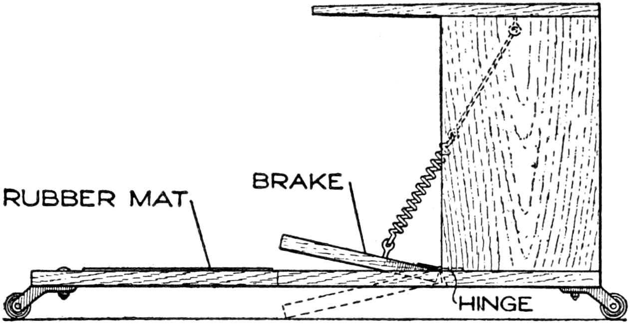
The Brake Is a Worth-While Addition to the Coaster from the Standpoint of Safety
Coasting on homemade devices is much enjoyed by children, but often accompanied with dangers because of difficulty in stopping quickly. The sketch shows a method of applying a simple brake to such a coaster, and the materials used may be obtained easily by boys in the home. The rubber mat indicated in the sketch gives a secure footing. The brake consists of a piece of wood, about 10 in. long and 3 in. wide. It is hinged to the base and held in a raised position by a coiled string, attached near the top of the device. A powerful pressure is obtained by throwing the rider’s weight on the pedal.
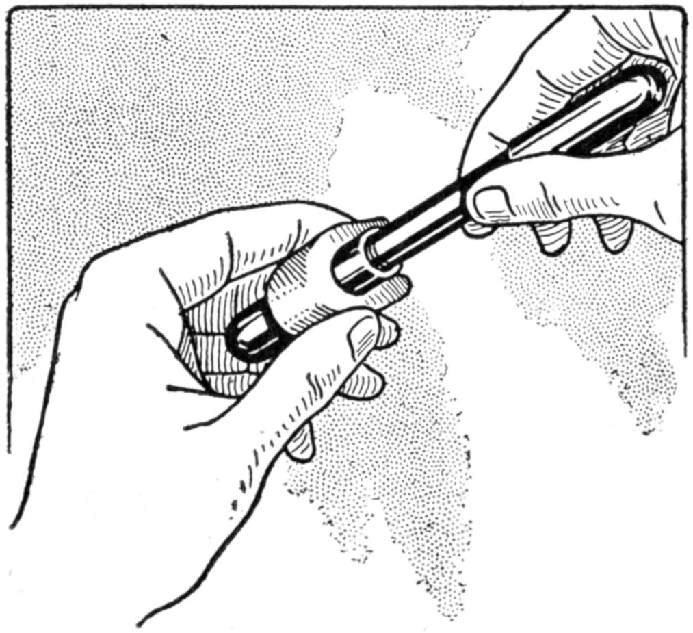
The Eraser Aids in Gripping the Barrel
Experiencing considerable difficulty in unfastening the parts of my fountain pen, I pressed into service an eraser in the method illustrated. The grip on the pen parts was positive and resulted in quickly releasing them without marring the surface or injuring the fingers.—Contributed by Charles R. Mellen, Jr., Geneva, N. Y.
[274]
Aquatic pleasures and sports at a summer camp or lake may be considerably enlivened by the building of a diving tower like that shown in the sketch. It has proved very successful at a boys’ summer camp at Crystal Lake, Ill. The boys have made a practice for several years of building a tower early each swimming season on the opening of their camp in July and disposing of it for about $5 at the close of the camp some weeks later. This covers the cost of the lumber, and several resorts and cottages now boast towers made by the campers.
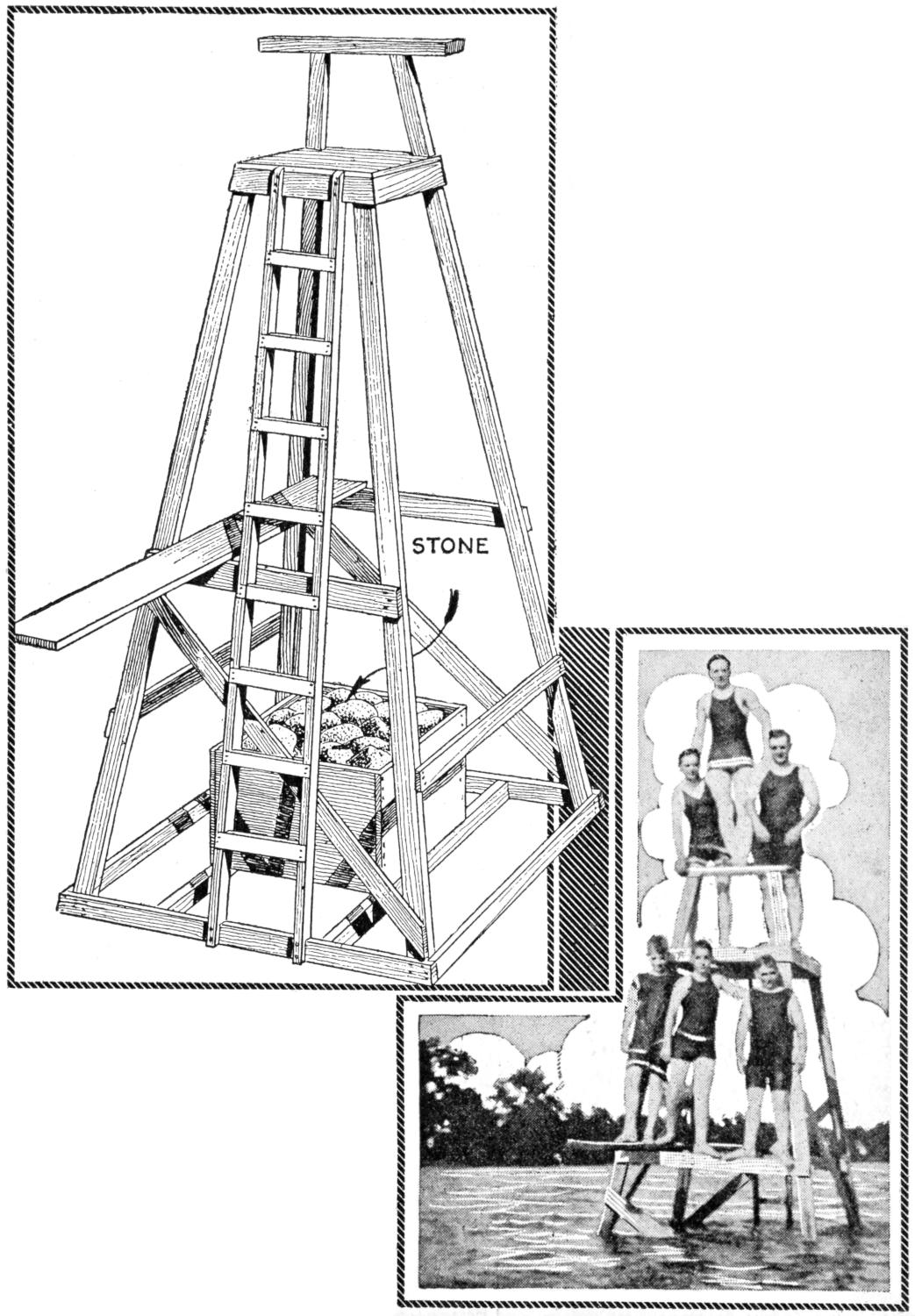
Boys at a Summer Camp Construct a Diving Tower Each Summer and Dispose of It for the Cost of the Lumber When They Break Camp. The Tower is Built Largely of Two by Four-Inch Stock and is Weighted with a Box of Stone. At the Right Is a Reproduction of a Photograph Showing the Builders Putting Their Diving Tower to Use
The tower is built largely of 2 by 4-in. stock. The longer pieces at the corners are 12 ft. in length, slanted so that the lower end of the tower is 7 ft. square and the platform at the top 3 ft. square. The handrail at the top is fixed to extensions of the rear uprights. A spring board is fastened on two horizontal braces near the middle of the tower, and is reached by the ladder. The structure is built on the shore and towed out to its position. It is sunk and weighted by the box of stone supported on cross braces.—Contributed by F. D. Lewis.
I spent several interesting hours in experimenting with gas mantles which I made at home, and the process should be of interest to others. While I did not succeed in making mantles of the quality of the commercial article, they were nevertheless successful and gave light. Magnesium produces a white light when ignited. By using common Epsom salts, which contain magnesium sulphate, I made a strong solution in distilled water. I soaked a piece of gauze bandage in the solution, dried it carefully and soaked it again a number of times, drying it after each immersion. By this time the cloth was stiff with the dry salt. When held in a flame, the cloth catches fire and burns[275] out, leaving the skeleton of magnesium sulphate. This framework, when held in the flame, glows with an intense white light. I shaped a piece of the gauze like a commercial mantle and dipped it into the solution as explained. It proved quite satisfactory.—Contributed by Victor E. Carpenter, South Bend, Ind.
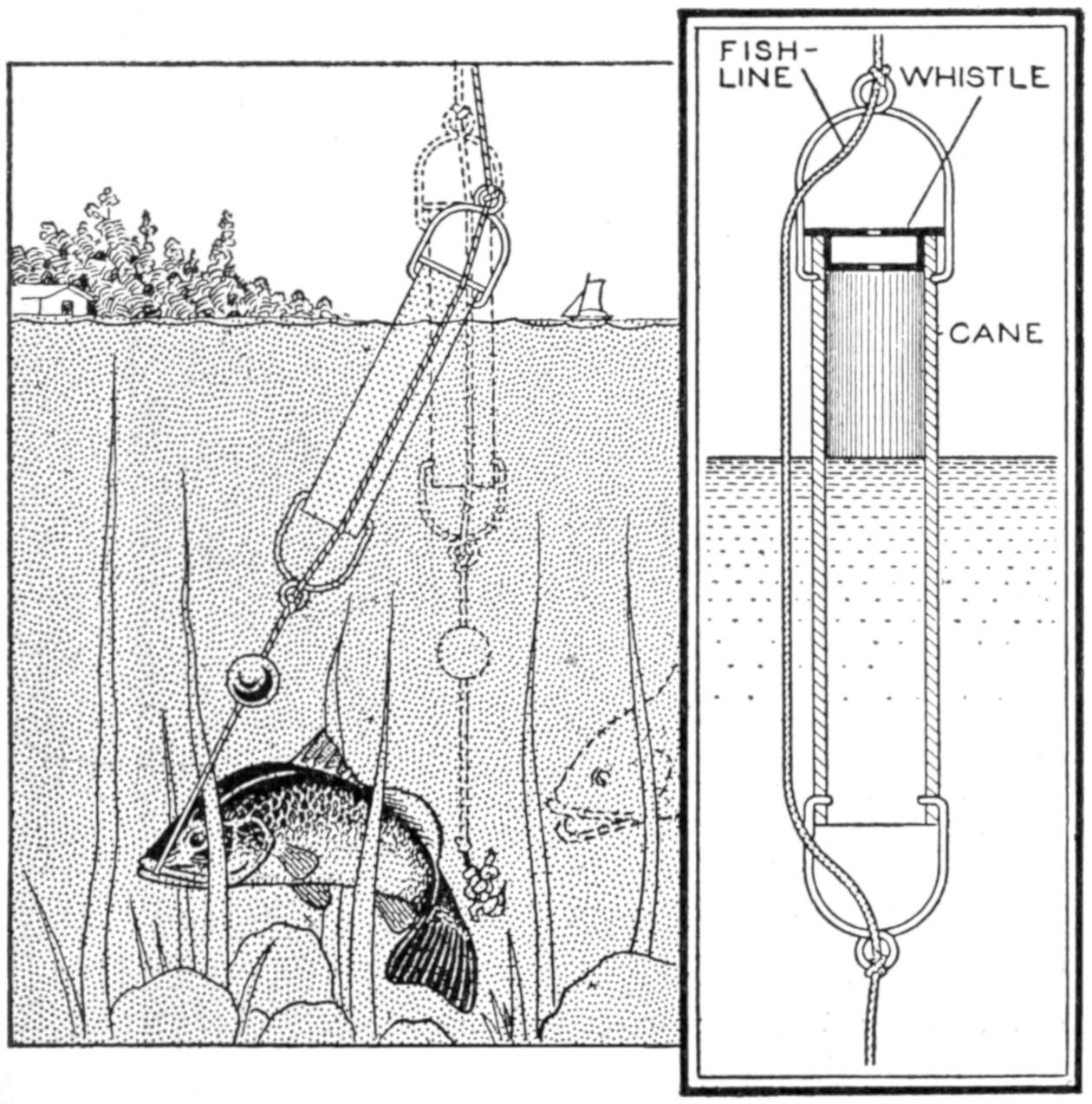
When the Fish Strikes the Bait the Water is Forced Up into the Whistle Suddenly, and the Escaping Air Warns the Fisherman
A toy railroad wheel, a piece of hollow cane, and pieces of wire are the materials necessary for making the whistle shown in the illustration, which warns a fisherman that a fish is attempting to make away with his bait. The wheel is fitted into the end of the cane and wedged into place to form a tight joint. The wires are formed into loops at the ends of the cane and fixed to it. The whistle is attached to the fishline, as shown, with the open end down and slightly below the surface of the water. The fishpole may be fixed so that the whistle will remain in this position while the fisherman is at ease in the shade near by. When the fish attempts to make away with the bait, as shown in the sketch, the water forces the air in the upper part of the cane out through the center hole of the wheel, and a whistling sound is the result.
Small craft, particularly those used for fishing or on streams where a current is encountered, should be provided with an anchor. The illustration gives details for making one that is simple in construction and inexpensive. It weighs about five pounds, and is heavy enough for light craft up to 18 ft. long.
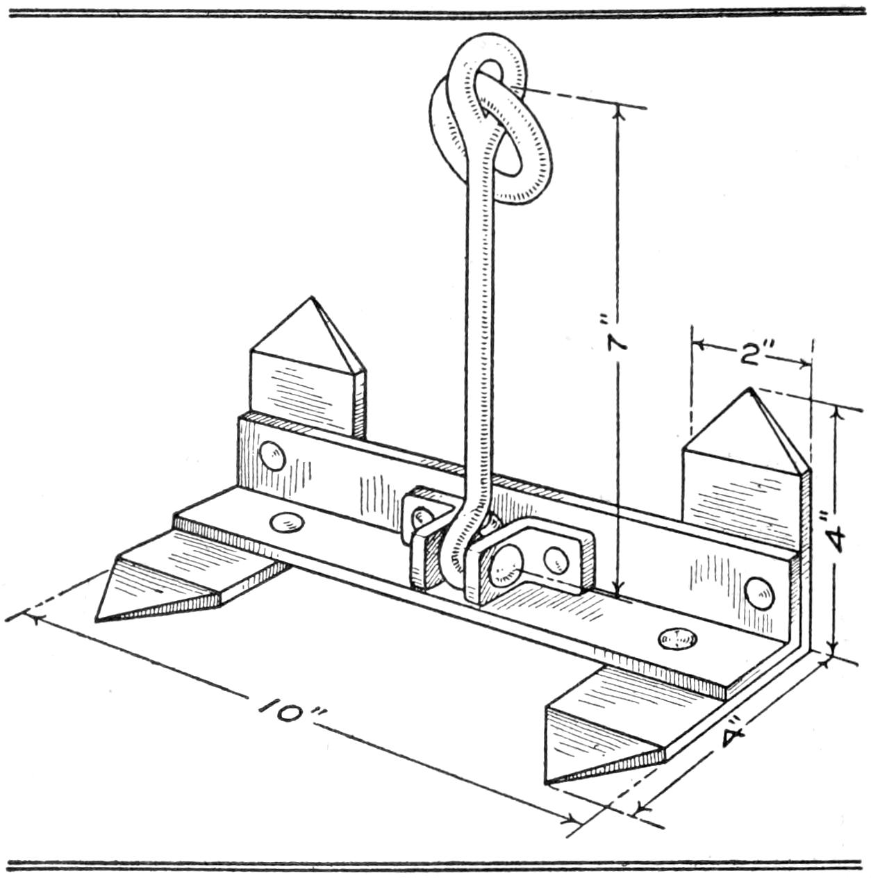
This Homemade Anchor Is a Practical Addition to the Equipment of a Canoe or Small Boat, and Weighs Five Pounds
The main section was made of a piece of 1¹⁄₂-in. angle iron, 10 in. long. The flukes, or endpieces, were made of sheet iron, 2 in. wide and 8 in. long, bent at a right angle, and riveted in place. The straps which hold the link, permitting it to swing freely, were made of band iron. The link was made of an old bicycle crank, into which a ring was forged. It may be made of iron rod, forged into the desired shape and fitted with a ring. A convenient method of handling the anchor on a boat is to run the line through a pulley at the bow and fasten the end of it to a cleat, near the seat of the person handling the craft. Care must be taken, in a canoe or small boat, that sufficient line is provided to reach the bottom of the anchorage, as otherwise the craft may be overturned.—Contributed by B. E. Dobree, Battleford, Sask., Canada.
¶The use of gasoline instead of turpentine for a thinner will prevent the sagging of colors in striping.
[276]
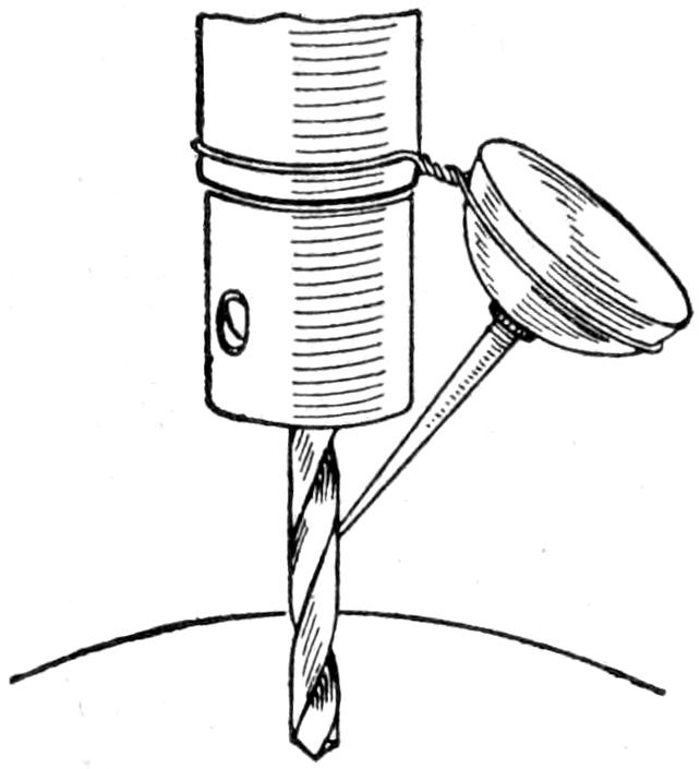
On stationary hand-power drill presses, where both hands are required to turn the crank and hold the work, some means must be provided for applying lubricant to the drill, or the machine would have to be stopped from time to time to apply the oil. A very handy arrangement, for pouring the oil on automatically, is to make a support of wire to hold an oilcan, as shown. This will provide a slow and constant dropping of oil on the bit.—Contributed by Bert Verne, San Diego, Cal.
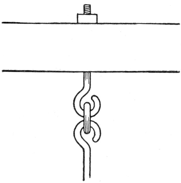
To have the playground swing work easily and without friction make the hangers as shown in the sketch. The ring in the hooks produces a slight rolling action and gives the swing a free motion.—Contributed by Edwin J. Bachman, Jr., Fullerton, Pa.
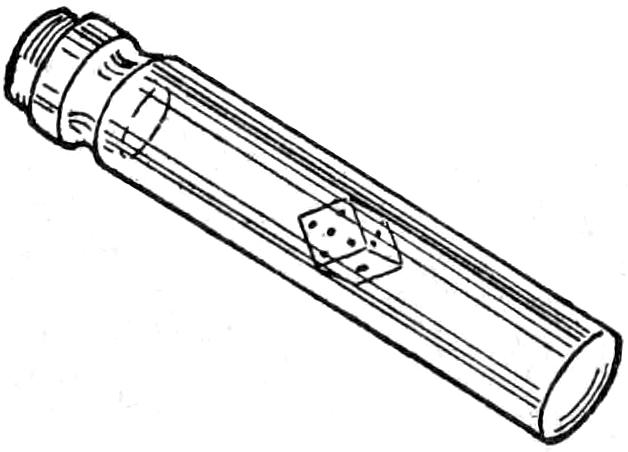
The die is made of cork and the spots painted white. A small round bottle is procured, the die is placed in it and the bottle is filled with water. Be sure to have enough water to prevent any air bubbles when it is corked tightly. The cork is then sealed in the bottle. If there is an air bubble, the cork die will not work well.
If the bottle is held bottom up, the cork die will spin around and float up against the bottom of the bottle where the number of spots can be seen. It is impossible to manipulate the die to turn up any desired spots, this being left entirely to chance. A number of bottles can be prepared so that any of the dice games can be played.—Contributed by Henry J. Marion, Pontiac, Michigan.
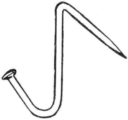
After an unsuccessful attempt to hang a small picture with a common pin, I devised the following method: After bending about ³⁄₈ in. of the point on an ordinary pin to an angle of about 45 deg. and bending up the other end in the opposite direction to form a hook, I drove the point on a downward slant into the wall. It went in easily and did not mar the plaster. When making a test I found that the hook would readily support a weight of several pounds.—Contributed by C. P. Smith, E. Radford, Va.
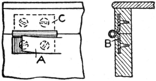
In making fancy boxes where ordinary hinges are used, a much neater job can be done if as much of the hinge as possible is covered. This can be done by carefully raising a sliver with a sharp chisel as at A. The wings are bent at an angle, as shown at B, and are then set in place, as shown at C. The sliver is carefully glued back in place over the hinge wing, and the surface is leveled with sandpaper.
¶A bit of rubber insulation stripped from an electric wire makes an excellent holder for a scarfpin.
[277]
Cord hammocks may be made in two or more different ways, the knots being formed by the simple overhand tie, Fig. 1; the flat reef knot, Fig. 2; the Solomon’s knot, Fig. 3, or by the triple throw-over, Fig. 4; or they can be knotted by the process known as netting, Fig. 5, in which a special needle, or shuttle, is used.
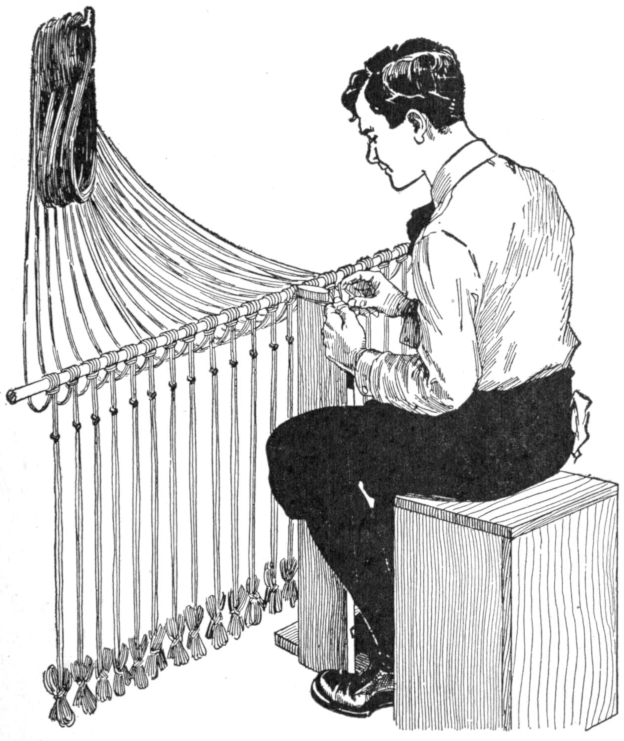
When Making a Hammock With the Simple Overhand, Flat Reef, or Solomon’s Knot, Loop All the Pairs of Cords at the Center about a Rod
In using any one of the first three methods of making the knots it is necessary to have cords arranged in pairs and long enough to reach from one end of the hammock to the other, allowing only sufficient length for the take-up in tying the knots and the spread of the meshes. The overhand knot is large, and the Solomon’s knot is a little unwieldy, but is considered more beautiful when tied. The flat reef knot is small, is easily tied and will not slip. The netting process has a good knot and has the advantage of a short single cord, as the meshes are made independently and the cord is carried on the netting needle.
It is a great advantage, when making a hammock with the simple overhand, the flat reef, or the Solomon’s knot, to loop all the pairs of cords at the center about a rod, Fig. 6—which may be any stick such as an old broom handle—knotting from the center toward each end, one side being tied, and then the other. When the first pairs are being tied, the opposite ends should be looped up together out of the way. Even half the length of a hammock makes a long cord to be drawn through each time a knot is tied, and each string can be wound about the fingers into a little bundle and secured with a half hitch, using the same cord, and left hanging, as shown in Fig. 7, allowing sufficient cord free to throw large loops in the tying, and to make about 10 additional meshes. About 3 ft. would be a good length to be left free.
It will be necessary to have 24 pairs of cords—48 cords in all—each 18 ft. long to make a hammock by the first two methods of tying the knots. Seine twine of medium-hard twist and 24-ply can be obtained from a store carrying sporting goods, and is about the best material to use for this purpose. When these pairs of cords are looped on the center rod, and the rod has been anchored to a wall, as shown in Fig. 8, begin by placing the mesh stick, or rather the mesh post, Fig. 9, between the first pair of cords, A and B, at the left end of the center rod, as in Fig. 8 and Fig. 6. The simple device illustrated in Fig. 9 is very useful for tying any one of the three first-described[278] knots. The device needs no explanation other than the illustration. It will be seen that there are two sizes on the top of the post; the smaller is for the first time across only. The mesh post should be of convenient height for a person when sitting on an ordinary chair. One foot rests on the base as the tying proceeds, but there is no pulling over, as the tie draws both ways on the post, this also doing away with the pull on the center rod.
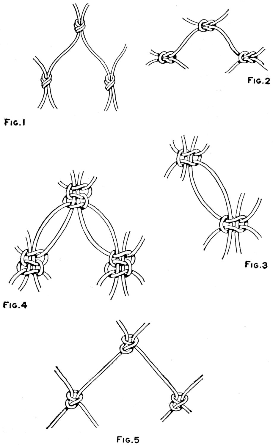
| Fig. 1 | Fig. 2 |
| Fig. 4 | Fig. 3 |
| Fig. 5 | |
The Simple Overhand, Flat Reef, Solomon’s Knot, Triple Throw-Over, and Netting Ties
The cord to the right, B, is taken in the right hand and thrown over the left cord A, Fig. 8, and is held by the left hand. The left cord A is then tucked down behind the right, as shown in Fig. 10. If the right cord goes over in making the first loop, the same cord B must also go over in the second throw, as in Fig. 11, in order to have a proper square knot that will not slip. The end of A is then tucked under B, as shown by the dotted lines. This makes a very serviceable knot for the hammock, but can be also used for other purposes. The knot is shown in Fig. 2. Draw it up tightly, very hard, for knotting is not worth much if it is not tied well.
In case the simple overhand knot is preferred, the mesh post is placed between the first pair as before, and cords A and B are brought to the front as in Fig. 12, but are carried parallel into a large loop that is thrown over as illustrated, then tucked up through as indicated by the dotted lines. The thumb and first finger of the left hand now slide up to the point P, while the right hand pulls up the loop as it nears the finish, the thumb and first finger crowding the loop down hard against the mesh post. The small part is used for the first row across. The knot formed is shown in Fig. 1.
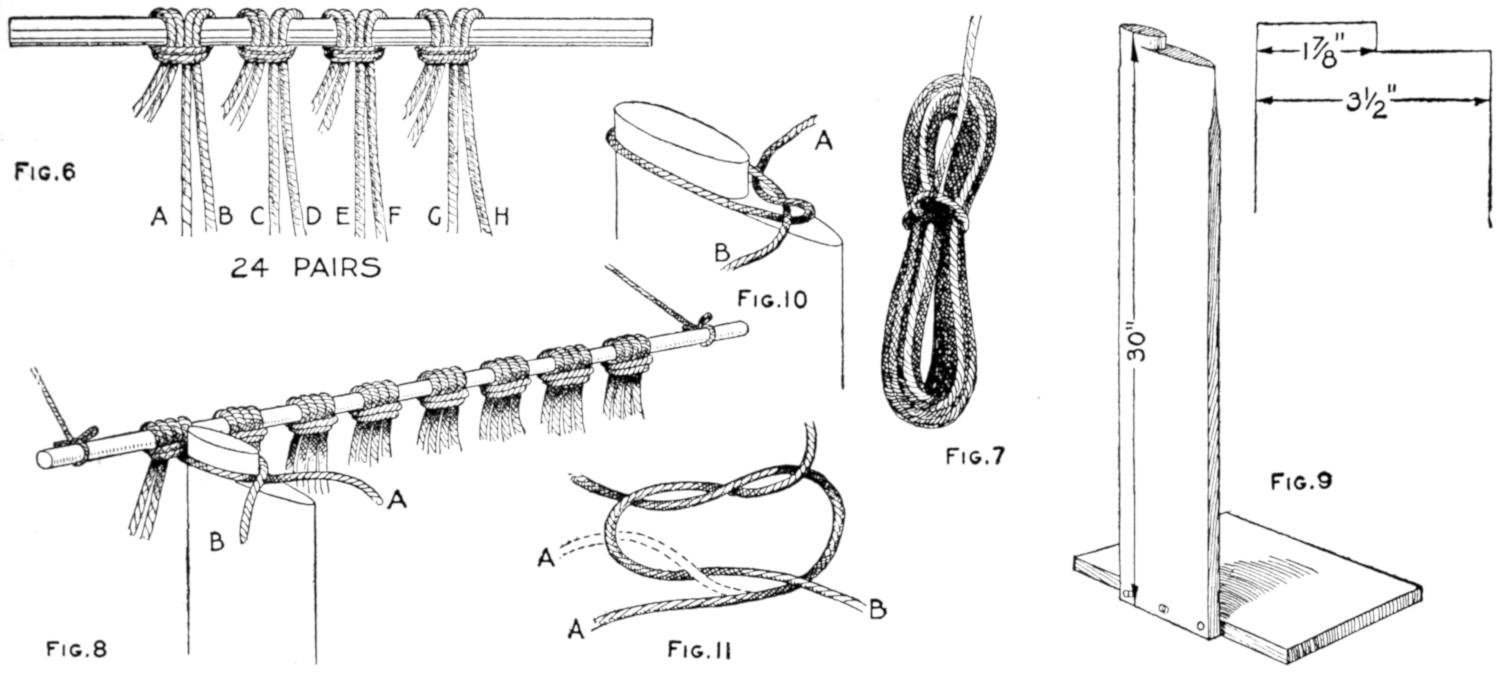
| Fig. 6 | Fig. 10 | Fig. 7 | Fig. 9 |
| Fig. 8 | |||
| Fig. 11 |
The Mesh Post Has Two Sizes on Its Upper End, the Smaller for Knotting the First Row of Meshes, and the Other for the Remaining Rows. This Illustration Also Shows the Manner of Tying the Knots
After tying the first pair of cords using the knot preferred, slip the first mesh so made off the tying post and place the post between C and D, which is the next, or second, pair. Tie the second pair and pass on to the third pair, which is E and F. Continue moving and tying until all the 24 pairs of cords have been similarly knotted in their first mesh. The last knotting will be the twenty-fourth pair, which is represented by the cords marked Y and Z. Instead of tying cords of the same pairs on the return trip across, one cord Y of the twenty-fourth pair is tied with one cord X of the twenty-third pair, and the other cord W of the twenty-third pair is tied with the cord V of the twenty second pair, and so on across the series.
On the second row of tying, the post is first placed between cords Y and X and they are knotted together, but instead of tying about the small part of the post the larger size is used. After cords Y and X have been tied, cords W and V are combined. It will be seen that this is tying the pairs together instead of combining the two cords of the same pair. The third time across the combinations are the same as in the first row. The large mesh is used on[279] all but the first row. The alternations of rows is continued until the cords are tied to within 2¹⁄₂ ft. of the end.
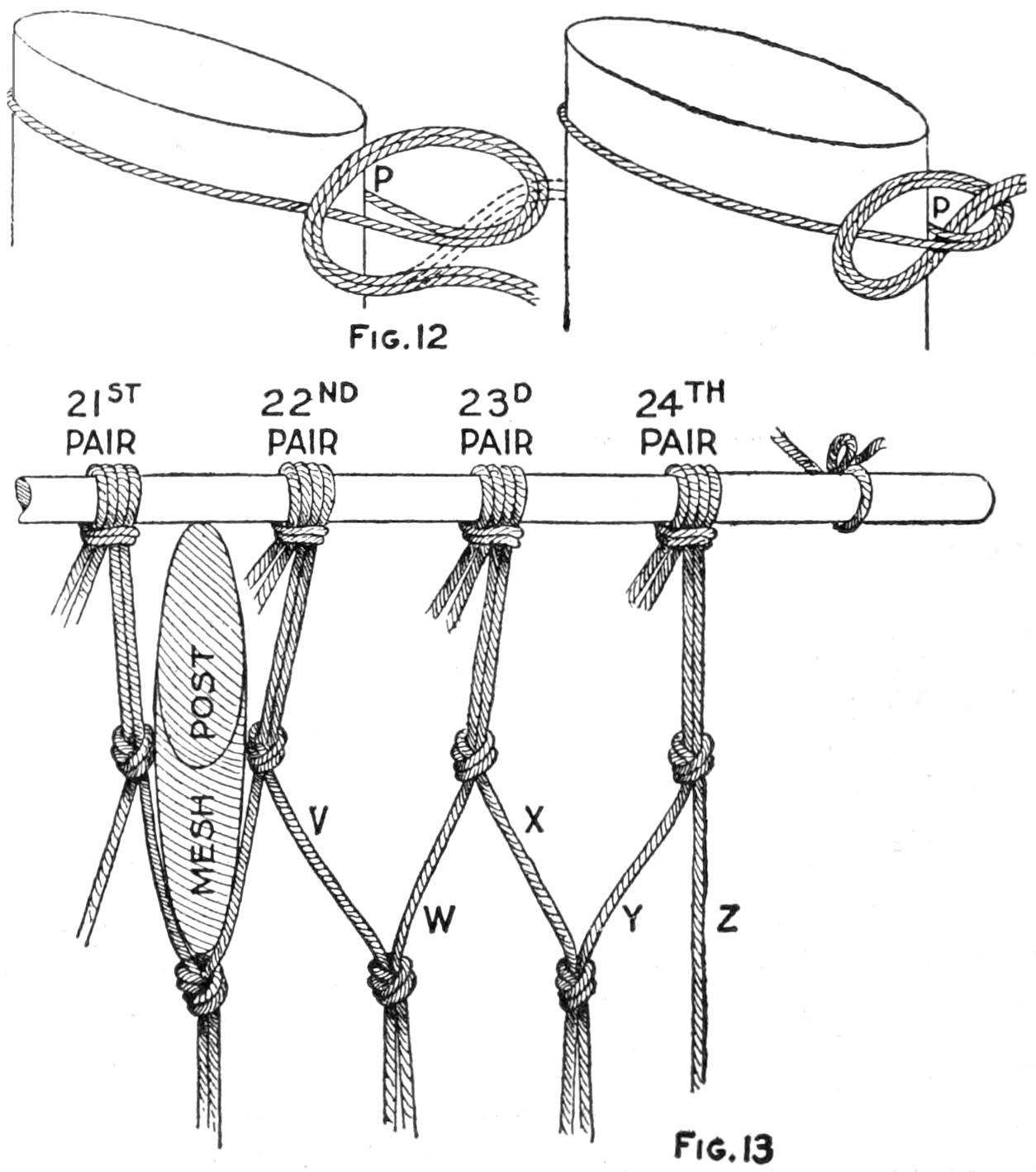
Fig. 12
Fig. 13
Tying the Overhand Knot and How to Run the First and Second Rows Across
Pull out the center rod, insert it in the second row of meshes, loosen the ends that were looped up and begin the knotting of the opposite ends of the cords. When both sides are completed to within 2¹⁄₂ ft. of the ends, the center rod is removed and inserted in the last row of meshes. Another simple device will be found efficient, which consists of a board, 30 in. long, three or more inches wide and 1 in. thick, with three nails driven in slanting, as shown in Fig. 14, to prevent the ring and rod from slipping off as the tying proceeds. One 2¹⁄₂-in. galvanized ring will be required for each end. The ring is attached to the single nail at the end with a string. This will be found better than just slipping the ring over the nail, as it is necessary to have a little more play in putting the cords through for the tying. The distance from the rod to the ring should be 2 ft. The tie is made in pairs as before, one cord going under and the other over the side of the ring, using the flat reef knot. There will be a few inches of ends remaining after the tie is made and these are brought back to the main body of the cord and wound with an extra cord used for that purpose. The winding is started by looping the end of the extra cord, or string, about the whole bundle of cord together with the ends, pulling tightly and tying securely with the flat reef knot. This is illustrated in Fig. 15. The winding should be about 1¹⁄₂ in. long where the turned-back ends are cut off. Each time the cord is wound about the bundle it should be looped through its own winding and drawn tightly. This is practically the buttonhole loop. To finish the winding the cord should be given a double looping[280] through its own winding; then with an awl, or other pointed tool, work a way through the under side of the other windings so that the end may be brought out farther back and pulled tightly, to prevent unwinding when the pull comes on the hammock. Attach the ring to the opposite end in the same manner and the hammock is complete.
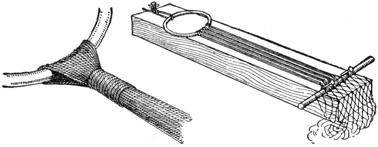
Attaching the Rings to the Ends of the Cords and the Binding near the Rings: All the Pairs of Cords are Looped about a Rod in the Center, and the Knots are Made toward the Ends
The edge can be bound the same as a tennis net, or a rope can be run through the outside meshes lengthwise, as desired. A very pretty effect can be obtained by knotting, in a similar manner to the body of the hammock, an apron fringe for the sides.
For the rapid and uniform hatching of cross sections this little device will be found to give results equaling most of the high-priced instruments that can be purchased. It consists of a hardwood block used in connection with a 45° triangle. The corners are cut to permit the triangle to slide the desired distance; then, by alternately sliding the triangle and block with the left hand, equal spacings can be drawn without measurements of any kind.
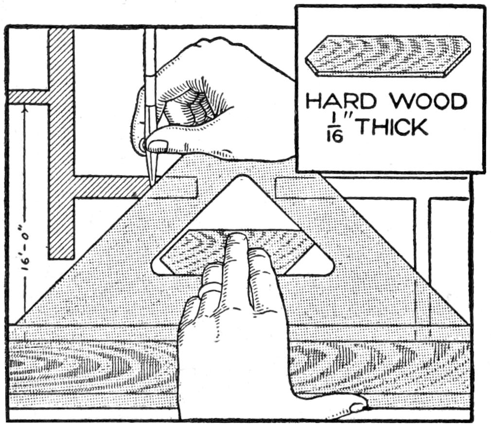
Block Used in a Triangle to Move It at Equal Distances for Making Section Lines
Two different spacings may be drawn with one block by reversing it and two blocks having a different location of the angles will give four spacings, which is about all the draftsman requires in ordinary practice. No alteration of the triangle is required with this device, and it requires but little skill to construct it.—Contributed by J. A. Shelly, Brooklyn, N. Y.
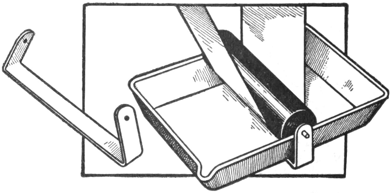
Roller Attached to Tray for Use in Developing a Full-Length Film
An ordinary tray can be used for film development, when there is no tank at hand, by the use of the attachment shown in the sketch. It consists of a strip of sheet metal, or tin, bent to fit under the tray and up on both sides to provide bearings for a roller. The roller is made of hard rubber and should be of such size that its lower surface will be under the developer in the tray. The film is drawn back and forth under this roller.
The window closer consists of a weight, A, attached to one end of a cord, B, which runs through several pulleys and has its other end attached to a hook in the center of the window sash, as shown in Fig. 1. The weight A is held in an elevated position by a small trigger which is operated with an electromagnet.
The arrangement of the weight and its control is shown in Fig. 2. The latch C is held in a horizontal position[281] by an extension on the arm D, which in turn is held by a latch, E. The latch C is mounted on the same supporting shaft as the arm D, and they are connected with a coil spring having the tension in such a direction that it holds the latch C down on the extension of the arm D. When the weight moves up through the box the latch C will rise and allow it to pass down beside it. The latch holding the lower end of the arm D may be released by means of an ordinary vibrating bell arranged so that its clapper will strike the extension F on the latch and thus cause its upper end to move from the engagement with the arm D. A small coil spring is attached to the arm D so that it will be returned to its vertical position when the weight has passed C and thus make it ready for the next operation without any adjustment except raising the weight and setting the clock.
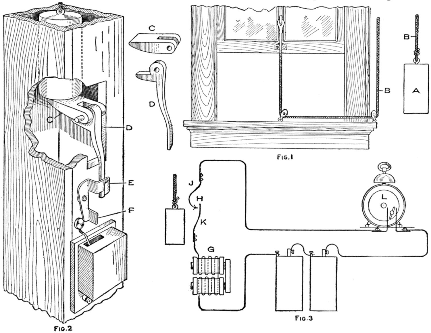
| Fig. 2 | Fig. 1 |
| Fig. 3 |
The Window is Automatically Closed by a Weight at the Time Set on the Alarm Clock When the Key Closes the Electric Circuit, Causing the Magnet to Release the Latch
A diagram of the electrical circuit is shown in Fig. 3, in which G represents the electromagnet to trip the trigger that supports the weight, and H the contact which remains open until the weight is raised to the upper position, when the spring J is forced against the spring K and closes the circuit. The circuit still remains broken until the contact L is closed by the key on the alarm clock, which is set in a vertical position between two springs representing the terminals of the wire. The contact H should be so located on the housing for the weight that it will be closed only when the weight is resting on the latch C. The circuit is then opened as soon as the latch C is released, and the clapper will stop vibrating.
¶When a pencil becomes too short for the hand, apply paste to about 1 in. of the rubber end, roll on a sheet of paper about 6 in. long, and almost all of the pencil can be used.
[282]
A good hammock should be about 12 ft. long, which includes 8 ft. of network and 2 ft., at each end, of long cords that are attached to rings. Seine twine, of 24-ply, is the best material and it will take 1¹⁄₂ lb. to make a hammock. The twine comes in ¹⁄₂-lb. skeins and should be wound into balls to keep it from knotting before the right time. Two galvanized rings, about 2¹⁄₂ in. in diameter, are required.
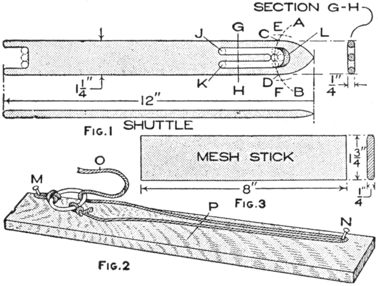
| Fig. 1 | Fig. 3 |
| Fig. 2 |
The Tools Necessary Consist of a Needle or Shuttle, a Guage Board, and a Mesh Stick
The equipment for netting a hammock consists of a wood needle, or shuttle, a gauge board for the long meshes at the ends, and a mesh stick for the regular netting of the main body of the hammock, all of which will be described in detail.
The shuttle is made of wood and is 12 in. long, 1¹⁄₄ in. wide, and ¹⁄₄ in. thick. The best material to use is maple or other hard wood, but very satisfactory ones can be cut from good-grained pine. The sketch, Fig. 1, shows the general shape of the shuttle, one end being pointed and the other forked. Lay out the pointed end before beginning to cut down to size. Place a compass at the center of the end, and with a radius of 1¹⁄₂ in. describe the arc AB. With the intersections of this arc and the side lines of the needle, C and D, as centers, and the same radius, 1¹⁄₂ in., cut the arc AB at E and F. With E and F as centers draw the curves of the end of the shuttle. The reason for placing the centers outside of the shuttle lines is to obtain a longer curve to the end. The curves can be drawn free-hand but will then not be so good.
The space across the needle at GH is divided into five ¹⁄₄-in. divisions. The centers of the holes J and K at the base of the tongue are 3¹⁄₂ in. from the pointed end. The opening is 2³⁄₄ in. long. Bore a ¹⁄₄-in. hole at the right end of the opening, and just to the left three holes, as shown by the dotted lines. With a coping saw cut out along the lines and finish with a knife, file and sandpaper. Round off the edges as shown by the sectional detail. It is well to bevel the curve at L so that the shuttle will wind easily. The fork is ³⁄₄ in. deep, each prong being ¹⁄₄ in wide. Slant the point of the shuttle and round off all edges throughout and sandpaper smooth.
The gauge board, Fig. 2, is used for making the long meshes at both ends of the hammock. It is a board about 3 ft. long, 4 in. wide, and 1 in. thick. An eight-penny nail is driven into the board 1 in. from the right edge and 2 in. from the end, as shown by M, allowing it to project about 1 in. and slanting a little toward the end; the other nail N will be located later.
The mesh stick, Fig. 3, should be made of maple, 8 in. long, 1³⁄₄ in. wide and ¹⁄₄ in. thick. Round off the edges and sandpaper them very smooth.
The making of the net by a specially devised shuttle is called “natting,” or netting, when done with a fine thread and a suitably fine shuttle. Much may be done in unique lace-work designs and when coarser material and large shuttles are used, such articles as fish nets, tennis nets and hammocks may be made. The old knot used in natting was difficult to learn and there was a knack to it that was easily forgotten,[283] but there is a slight modification of this knot that is quite easy to learn and to make The modified knot will be the one described.
The shuttle is first wound by looping the cord over the tongue, as shown in Fig. 4, then bringing it down to the forked end and up to the opening on the opposite side; then the cord is again looped over the tongue and returned to the fork or place of starting. Continue winding back and forth until the shuttle is full. The shuttle will accommodate from 20 to 35 complete rounds. If the shuttle is too full it crowds in passing through the meshes and delays the work.
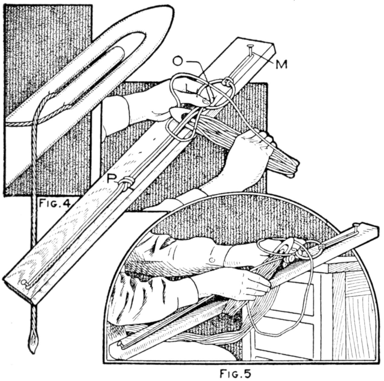
Fig. 4
Fig. 5
The Shuttle is First Wound and the Long Loops at One End Formed over the Gauge Stick
Attach one of the galvanized rings by means of a short cord to the nail in the gauge board, as shown in Fig. 2. At a point 2 ft. from the lower edge of the ring, drive an eight-penny finishing nail, N. Tie the cord end of the shuttle to the ring, bring the shuttle down and around the nail N; then bring it back and pass it through the ring from the under side. The cord will then appear as shown. A part of the ring projects over the edge of the board to make it easier to pass the shuttle through. Draw the cord up tightly and put the thumb on top of the cord O, Fig. 5, to prevent it from slipping back, then throw a loop of the cord to the left over the thumb and up over a portion of the ring and pass the shuttle under the two taut cords and bring it up between the thumb and the two cords, as shown. Draw the looped knot tight under the thumb. Slip the long loop off the nail N and tie a simple knot at the mark P. This last knot is tied in the long loop to prevent looseness. Proceed with the next loop as with the first and repeat until there are 30 long meshes.
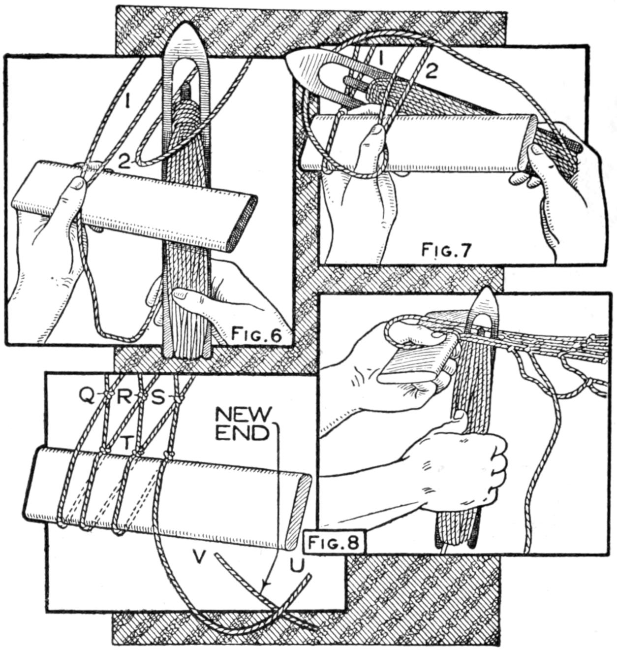
| Fig. 6 | Fig. 7 |
| Fig. 8 | |
After the Completion of the Long Meshes, the Ring is Anchored and the Mesh Stick Brought into Use
After completing these meshes anchor the ring by its short cord to a hook or other stationary object. The anchorage should be a little above the level for tying the knots of the net. Tie the cord of the shuttle to the left outside loop and always work from the left to the right; and the first time across see that the long meshes do not cross over each other, but are kept in the order in which they are attached to the ring.
After tying the cord to the mesh 1, Fig. 6, bring the mesh stick into use. Pass the cord down over the mesh stick, drawing the lower end of the loop down until it comes against the upper side of the mesh stick and put the thumb down upon it in this position to prevent slipping. Pass the shuttle[284] up through the loop 2 and draw that down to the mesh stick. Shift the thumb from the first position to the second. Throw the cord to the left over the thumb and about the loop 2, as shown in Fig. 7, and bring the shuttle under both of the cords of mesh 2 and up between the large backward loop and the cords of the mesh 2. Without removing the thumb draw up the knot very tight. This makes the first netting knot. Continue the cord around the mesh stick, pass it up through mesh 3, throw the backward loop, put the shuttle under and up to the left of the mesh 3 and draw very tight, and do not allow a mesh to be drawn down below the upper side of the mesh stick. Some of these cautions are practically repeated, but if a mesh is allowed to get irregular, it will give trouble in future operations.
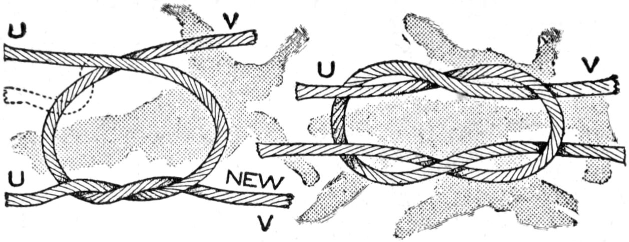
Fig. 9
Fig. 10
A Square Knot is Used to Join the Ends of the Cord When Rewinding the Shuttle
Continue across the series until all of the long loops have been used and this will bring the work to the right side. Flip the whole thing over, and the cord will be at the left, ready to begin again. Slip all the meshes off the mesh stick. It makes no difference when the meshes are taken off the stick but they must all come off before a new row is begun. Having the ring attached to the anchorage by a cord makes it easy to flip the work over. Be sure to flip to the right and then to the left alternately to prevent the twisting, which would result if turned one way all the time.
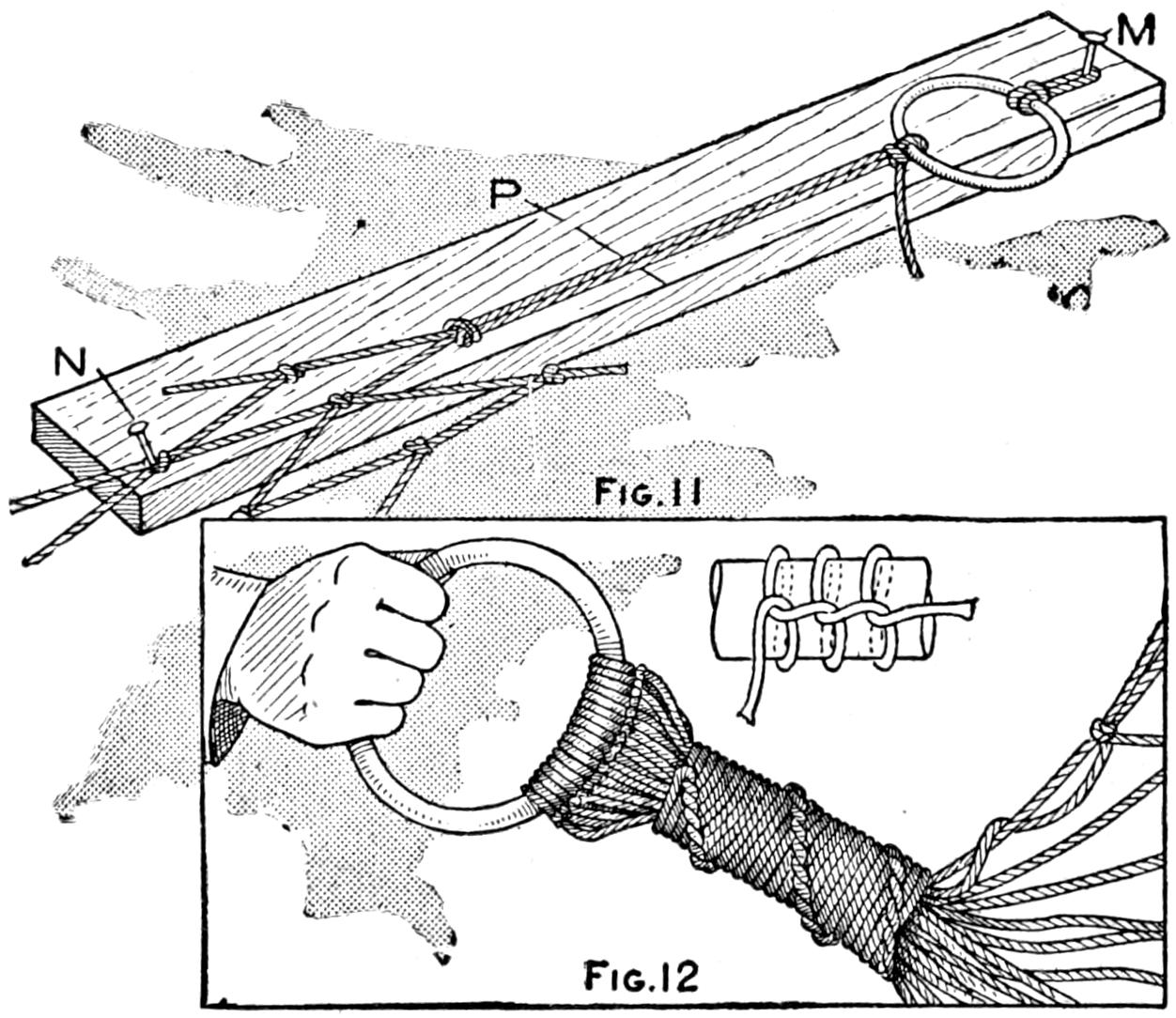
Fig. 11
Fig. 12
The Gauge Board is Again Used for the Long Loops at the Finishing End, Then the Cords are Wound
The first mesh each time across is just a little different problem from all the others, which may be better understood by reference to Fig. 8. The knots Q, R, and S are of the next previous series. The cord is brought down over the mesh stick and up through mesh 1, and when the loop is brought down it may not draw to the mesh stick at its center; it is apt to do otherwise and a sideway pull is necessary, which is pulled so that the knots Q and R are side by side, then the knot at T may be tied. When the mesh 2 is drawn down it should pull to place without shifting, and also all the others of that row.
Continue the use of the mesh stick until a net 8 ft. long is made. When the cord gives out rewind the shuttle and tie with a small knot that will not slip. The weaver’s knot is good if known, or the simple square knot shown in Fig. 9 is very good. It is too easy to make to need direction, but unless it is thrown over just right it will slip. Let U, Fig. 8, represent the short cord and V the new piece to be added. Place the cord V back of U and give U a complete turn around V, Fig. 9, and bring them together at a point above U, then to the front. Repeat the complete turn of U about V, shown by the dotted line, and pull tightly. If analyzed, it consists of two loops that are just alike and linked together as shown in Fig. 10.
When the 8 ft. of netting has been completed, proceed to make the long loops as at the beginning. The same gauge board can be used, but the tying occurs at both ends, and since the pairs cannot be knotted in the center, two[285] or three twists can be given by the second about the first of each pair. The long loops and the net are attached together as shown in Fig. 11. Slip one of the meshes of the last run over the nail N, and when the cord comes down from the ring, the shuttle passes through the same mesh, and when drawn up, the farthest point of the mesh comes against the nail. After this long loop has been secured at the ring, the first mesh is slipped off and the next put on. All of the long loops at this end will be about three inches shorter than at the other end, unless the finishing nail N is moved down. This will not be necessary.
With a piece of cord about six feet long, start quite close to the ring and wind all the cords of the long loops together. The winding should be made very tight, and it is best to loop under with each coil. This is shown in Fig. 12.
The hammock is now ready for use. Some like a soft, small rope run through the outside edges lengthwise, others prefer a fringe, and either can be added. The fringe can be attached about six meshes down from the upper edge of the sides. The hammock should have a stretcher at each end of the netted portion, but not as long as those required for web hammocks.
A unique as well as practical fishing-line float can be made of a small gourd. After the gourd has dried sufficiently, wire loops, to hold the line, are inserted, or rather, a single wire is run through and looped at both ends. The contents of the gourd need not be removed. Dip the float in a can of varnish, or apply the varnish with a brush.
Those who wish to produce an arc light for experimental purposes, or for the brief periods required by photography, will find the method of construction shown in the sketch very simple and inexpensive. Using the short lengths of carbons discarded by moving-picture operators, there is no difficulty in maintaining a good arc for 15 minutes, or more, without once manipulating the adjusting screw at the top.
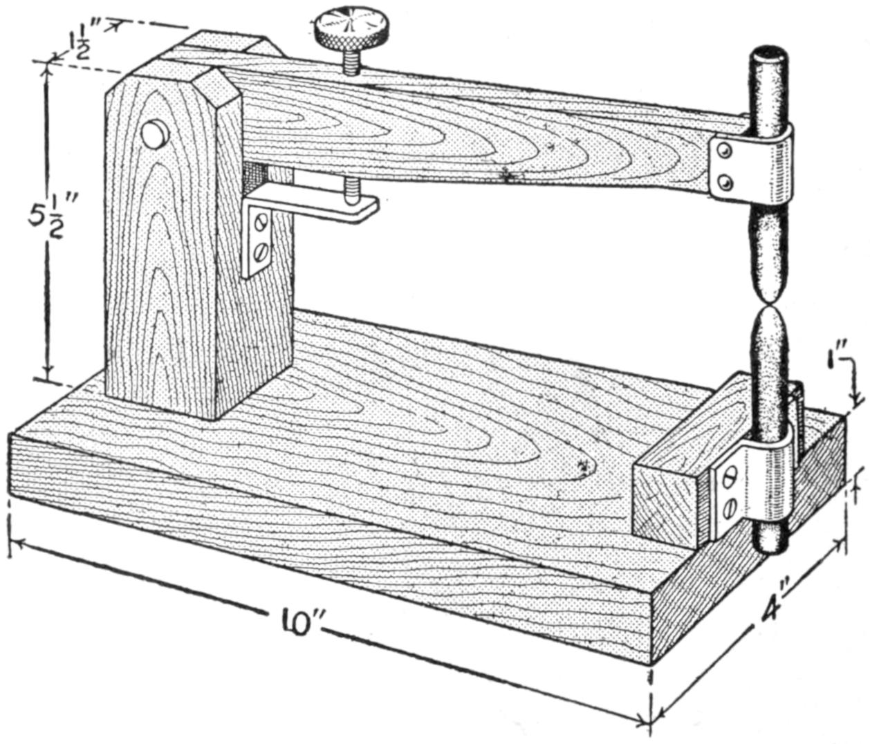
An Efficient Arc Light for Purposes Where a Light is Required for a Short Time
Only three pieces of wood are necessary besides the base, and in the preparation of these no particular care is necessary except to have the top arm swing freely up and down without any appreciable side movement. The carbon holders are merely strips of heavy tin, which need only be screwed up sufficiently tight to hold the carbons in place and yet permit their being pushed up when the top adjusting screw will no longer operate. This adjustment may be readily taken care of by means of a long, slender wood screw with the point filed off and a metal disk soldered to the top. Connections are made to the carbon holders either under a screw head or by soldering the wires to the metal.
In operating any arc light on the commercial 110-volt current some resistance must be placed in the circuit. An earthen jar of water with two strips of tin or lead for electrodes, will answer every purpose.
¶A small leak in an oil or water pipe on an automobile can be temporarily stopped by melting a piece of rubber over the hole.
[286]
A nicely polished animal horn may be turned into an article of utility instead of being merely used as a wall ornament, as shown in the illustration. An old lamp base, heavy enough to balance the horn, and secured to it with a bolt, is all that is needed to effect the transformation.
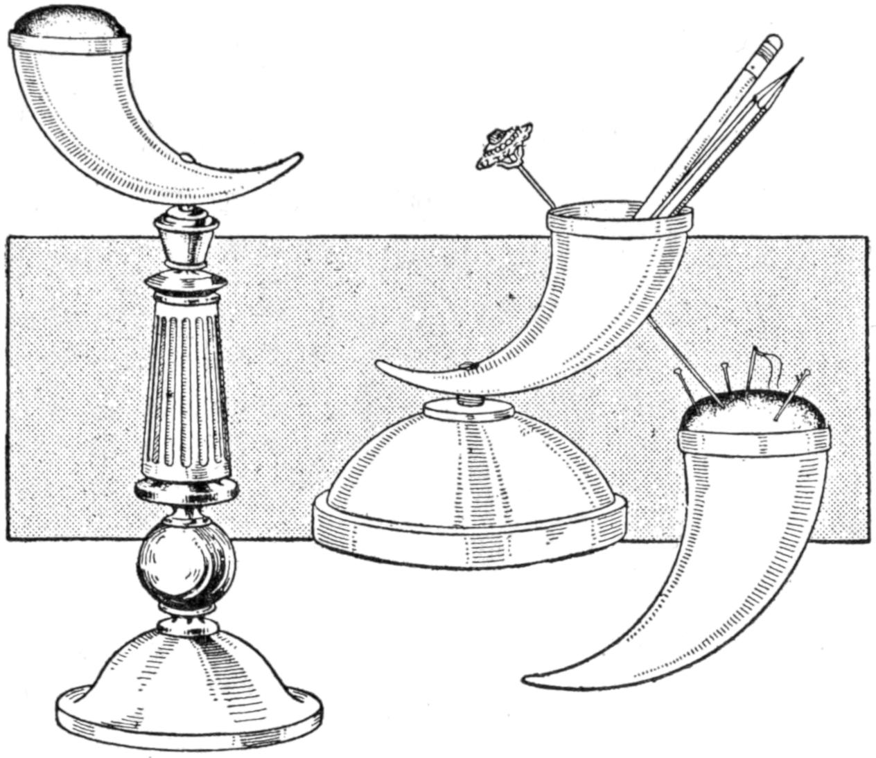
Fastening a Horn to a Base to Make an Ornamental Pen or Pincushion Holder
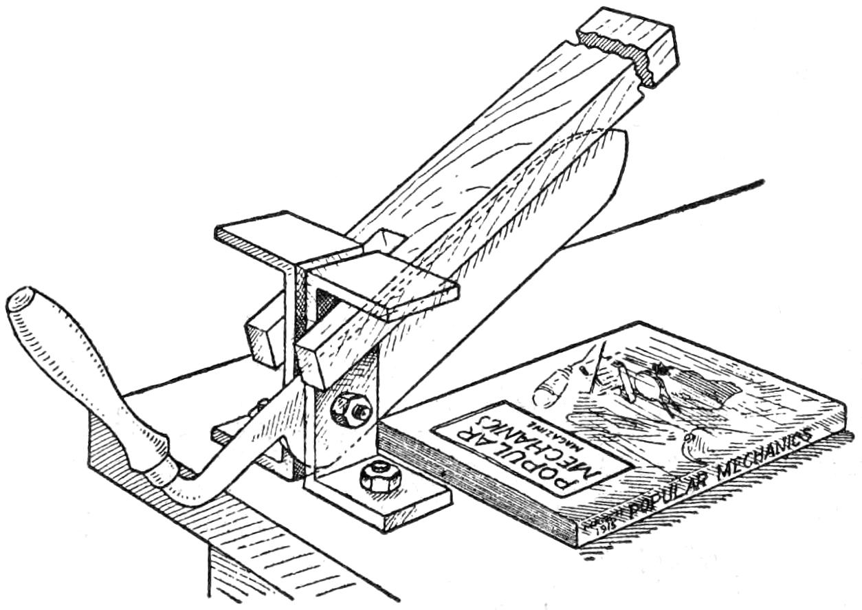
Cutter Made of a Large Straight-Edge Knife for Trimming Edges of Bound Magazines
There has been a number of descriptions telling how to bind magazines, but none how to trim the edges after having bound them. Desiring to have my home-bound volumes appear as well as the other books, I made a trimmer as follows:
Any large knife with a straight edge will do for the cutter. I used a large hay knife. A ³⁄₈-in. hole was drilled in the untempered portion near the back of the handle end. Two U-shaped supports were made of metal and fastened to the top of an old table, between which the knife was fastened with a bolt. A piece of timber, 6 ft. long, 4 in. wide, and 2 in. thick, was used as a lever. One end of this piece had a U-shaped notch cut in it to straddle the supports under the projecting ends. A board was attached to the table top, having one straight edge set where the knife edge would just pass it.
If the knife has a good sharp edge it will do very satisfactory work. When the edges are trimmed the knife can be removed and used for its original work.—Contributed by E. S. Mundell, Lowpoint, Ill.
While making a bunglesome job of patching a pair of rubber gloves, which I used to keep the stains from my fingers while developing photographic plates, a physician friend happened along and told me how to do it properly. The method is as follows: Procure a piece of card, such as heavy Bristol board used for filing cards; spread it on one side, rather thick, with ordinary library paste and stick it to the rubber tissue, preferably dentists’ rubber dam of light weight; smooth it flat, and let the paste dry. When a patch is needed cut one out, rubber and card together, and fit it to the cut in the glove. Put the glove on the hand inside out, moisten the patch with cement, let it dry for a few seconds and then press it in place hard. If the tear is large, it is easier to lay the moistened patch down and fit the edges of the tear to it, then press hard in place. After the cement has thoroughly dried out, soak the patch in water and remove the bit of card. This gives a patch fastened securely to the extreme edges; flat, water-tight, and as fit to stand boiling as any patch, for sterilizing. After removing the card, the glove is dusted with talcum.—Contributed by J. S. Hogans, Uniontown, Pa.
[287]
Boys in a manual-training class became very enthusiastic over the making of small chestlike boxes, bound with ornamental metal, and adapted them to a great variety of uses. The boxes were designed to suit the taste of the maker and for use as glove, handkerchief, jewelry, toilet, treasure and other boxes, lined with silk, and finished in wax and varnish, in various stains. Oak was used for most of them, and the metals employed were largely copper and brass, although silver is suitable for small boxes. They are simple in construction, as shown in the working drawings, and can be made in the home workshop. The photograph reproduced shows a group of boxes, for various purposes, and in several styles of metal binding. The long box at the top is for gloves or ties; the larger ones are for the boys’ personal use, caring for collars, handkerchiefs, etc.; the smaller boxes are for the dresser, providing for the care of jewelry and similar small articles. The boxes proved great favorites as gifts, and the monogram of the recipient may be etched into the metal.
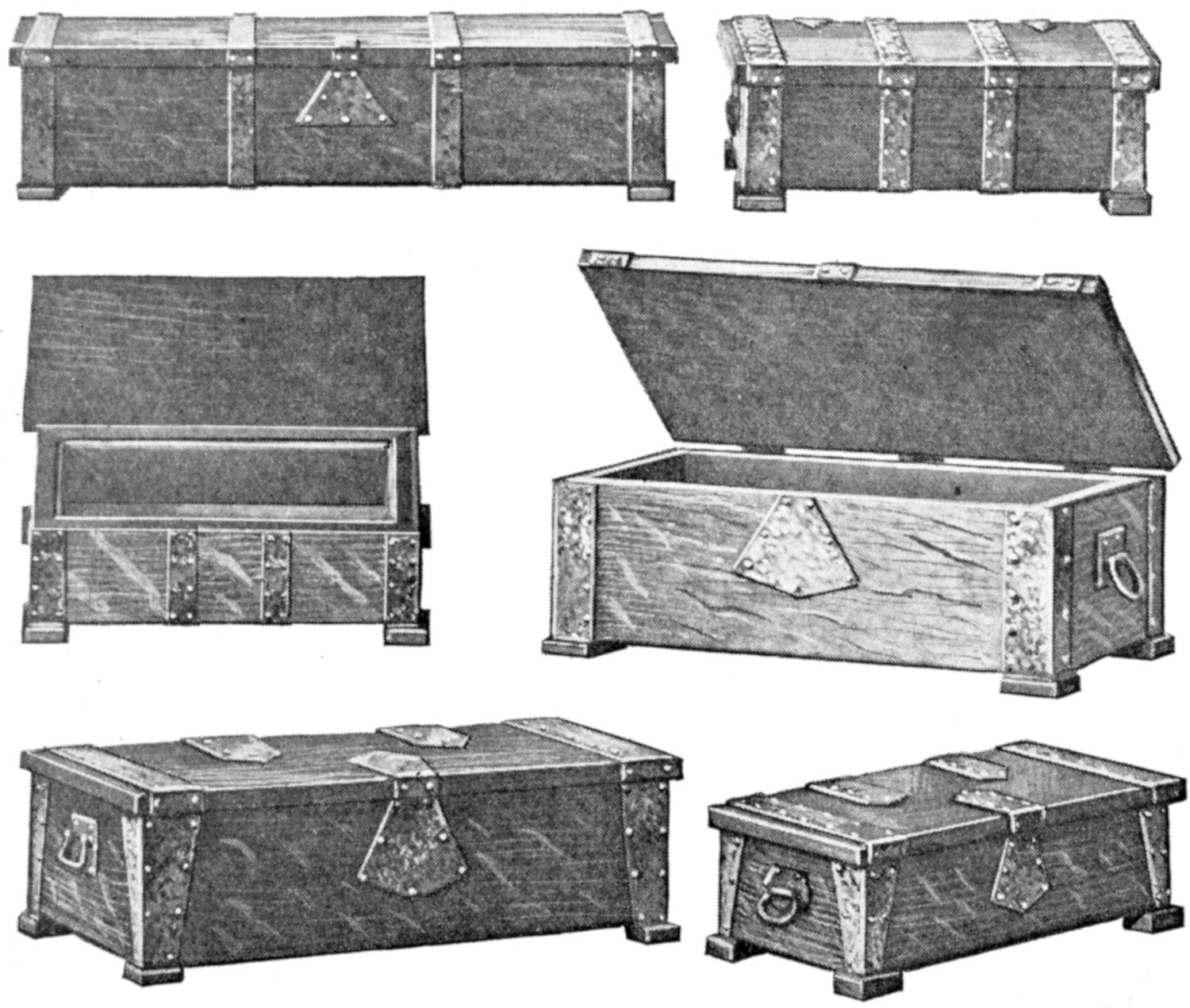
These Gift Boxes, Trimmed with Ornamental Metal, were Made by Boys in a Manual-Training Class. A Long Glove Box is Shown Above; the Larger Boxes Are for Handkerchiefs, and the Smaller Ones for Jewelry and Trinkets
Well-seasoned oak is the most suitable material for the making of the boxes, as it harmonizes well with the plain metal trimmings. The quarter-sawed variety is preferable, being more ornamental, and less likely to warp or twist. For most of the boxes, stock ³⁄₈ in. thick is suitable, although this may be cut down to ⁵⁄₁₆ in. for the smaller boxes, if convenient. The method of joining the pieces is similar in all the varieties of boxes, and the jewel box illustrated in the working drawings will be taken as a specimen. The sides of the box are butted against[288] the ends, lapping over them, flush, and nailed with small brads. The bottom is fitted between the sides and ends, and nailed so that the nails are concealed by the metal bands, at the four corners, and at other points, if bands are placed near the middle. The stock for the box is cut and finished on all sides to the following dimensions: all pieces to be ³⁄₈ in. thick; top, 4¹⁄₂ by 7¹⁄₂ in.; two sides, 1⁷⁄₈ by 7 in.; two ends, 1⁷⁄₈ by 4 in.; bottom, 3¹⁄₄ by 6¹⁄₄ inches.
All the pieces should be scraped carefully to a smooth finish, and the nails started with an awl, or a slightly flattened nail of the same size, fitted into a hand drill. Extreme care must be taken, in nailing, that the surface of the wood is not marred, which is likely to occur if the nails are driven into the wood too rapidly, or without starting holes for them. The feet are cut from a strip, ³⁄₈ in. thick and ³⁄₄ in. wide, the cut edges being sandpapered smooth without destroying the squareness and the sharp corners. They are nailed to the bottom of the box with brads, care being taken to have the end grain of each block at the end of the box, particularly if the metal trimmings do not cover the blocks.
The cover is fixed in place with small plain butts, countersunk into the wood, one leaf into the top and the other into the back of the box. A simpler method is to set both leaves of the hinge into the edge of the back. Care must be taken in fitting the hinges that they are set in line with the back of the box, and holes for the screws should be made before driving them into place. Too much care cannot be taken with the fitting of the hinges, as the proper fitting of the lid, both as to resting level and being in line with the edges of the box, depends on the fitting of the hinges.
After the construction work and nailing is completed, the box may be sandpapered carefully, rubbing in the direction of the grain, and being careful not to round off the edges unduly. The oversandpapering of woodwork marks the work of the careless novice. The box should be handled as little as possible while the metal trimmings are being fitted, and, before the finish is applied, should be gone over lightly with sandpaper to remove dirt. When the metal pieces are fitted, and ready to be fastened in place, the finish may be applied to the box. Warm browns or other dark-oak finishes, are best suited to the simple style of chest, and the metal fittings. A coat of stain should be applied, and this followed, when dry, by a coat of filler, rubbed well into the pores of the wood. The filler should be permitted to dry hard and the surface is then sandpapered very lightly with a fine grade of paper—No. 00 is best. Do not rub through the filler or stain, particularly at the corners. Wax is the most readily applied outer finish. Several coats may be used to give a substantial finish. A coat of shellac, followed by coats of rubbing varnish, dried well and rubbed between coats with No. 00 sandpaper may be applied for a high-gloss finish. This is a more involved process and requires that the varnish be rubbed down with pumice stone and water, and finished with an oil polish.
Copper or brass, of No. 20 gauge or lighter, is suitable for the making of the trimmings. The details of the handles are shown in the sketch, at the right. Cut a back plate, ⁷⁄₈ in. by 1¹⁄₄ in., and fit the handle of wire to it by means of a strap, bent from a strip of metal, ³⁄₈ in. by ⁷⁄₈ in. The other bands are merely strips, ¹⁄₂ to ³⁄₄ in. in width and fitted to the size of the box, where applied. Strap hinges of the same metal may be made, but the most convenient method for the amateur is to fit the metal strips into place at the hinges, merely as ornamental features. Various types of locks may be fitted into the box, and for the worker having the necessary skill, it is interesting to make a hasp, as indicated in the sketch.
The designing and making of the metal trimmings affords unlimited opportunity for originality, and a good plan is to fit the desired strips, cut from paper, to the box before making them of the metal. It is well to remember,[289] in this connection, that the simple bands and forms are better suited to the plain box than ornate trimmings. Having determined upon suitable patterns for the metal strips, cut them from the sheet with snips, or tinner’s shears, care being taken to produce a smooth edge. A file may be used to remove roughnesses and to round the edges of the metal slightly. The metal is fastened with escutcheon pins, which add to the ornamental effect if properly spaced. Holes for them must be drilled, or punched, through the metal.
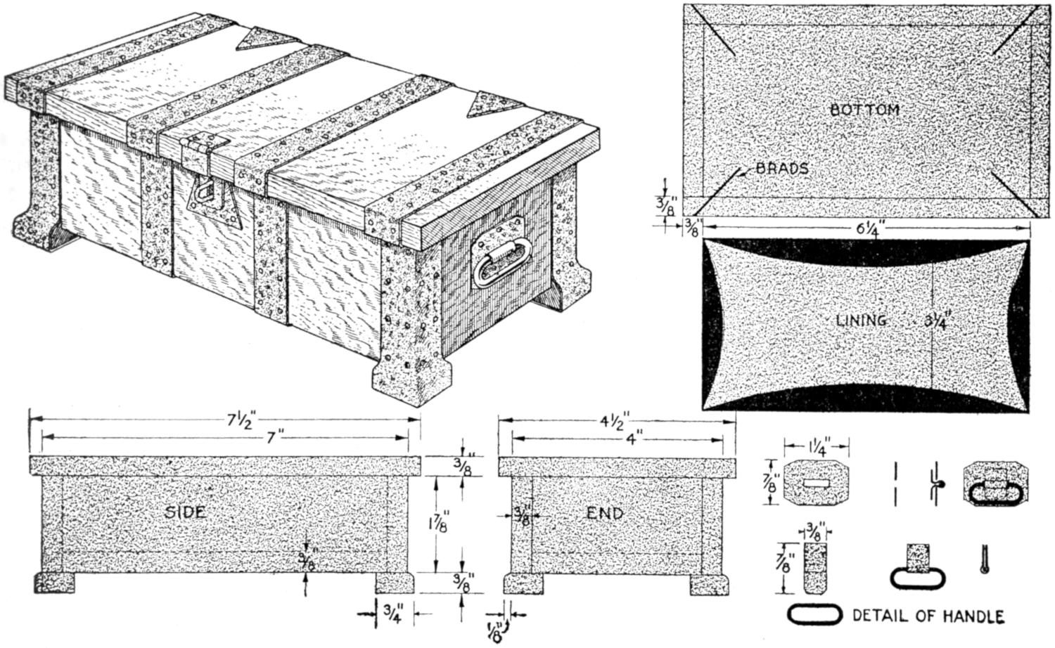
The Construction of the Jewelry Box Is Typical of the Others. The Handle is Shown in Detail. The Nailing of the Bottom and the Fitting of the Lining are Shown at the Right
The metal may be left smooth and polished, or hammered with the round end of a ball-peen hammer, to produce the dented effect shown on several of the boxes in the group. This, as well as other finishing of the metal, must be done before it is fixed in place. Beautiful colors may be given to the metal by heating it, and observing the colors as they “run.” A trial will enable one to judge the proper heat for the various colors, which “run” from a light straw to a deep purple, with various reddish intermediate tones. A brown oxidized finish, or a verd-antique—greenish—finish may also be obtained. The metal should be polished with wax to preserve the finish if other than the latter type is used.
The boxes are lined with silk or other suitable material. The method is as follows: Cut cardboard pieces to fit against the inner sides of the bottom, sides, and ends. Pad one side of them with cotton batting, and cover with silk, gluing the edges of it on the back of the cardboard, as shown in the sketch. By bending the pieces slightly, they may be inserted and glued in place. Care must be taken in handling the glue, that the silk is not soiled. Pads of felt, or chamois skin, may be glued to the bottom of the feet of the box, so as not to mar the surface upon which it rests.
The most popular boxes, which are especially suitable for gift purposes, are the jewelry, glove, and handkerchief boxes. Their dimensions are: jewelry box, 2³⁄₄ by 4 by 7¹⁄₂ in.; glove box, 3¹⁄₄ by 5 by 13 in.; handkerchief box, 4 by 6 by 10 in. Other sizes suited to special purposes may, of course, be designed readily, and made in walnut, mahogany, or other cabinet woods.
[290]
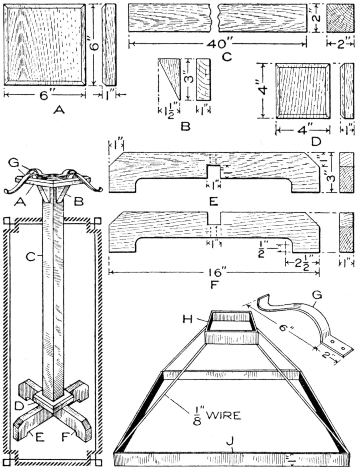
This Lamp of Substantial Construction and Pleasing Design may be Made at Small Cost. The Pedestal Assembled is Shown at the Left and Details of the Parts and of the Metal Frame for the Shade, Above
The lamp illustrated was designed for use in reading, the doing of hand work at which one is seated in a chair away from a table lamp, or for lighting a piano rack. It is light, readily moved about, easily made, and of pleasing design. It combines construction in wood and metal, is inexpensive, and within the range of a careful amateur craftsman. The pedestal is shown assembled at the left, and above are detailed sketches of the parts. The construction of the shade, which is 18 in. square, is shown at the right. The central post is 40 in. long and 2 in. square, and the base measures 16 in. on the arms.
The stock bill for the lamp is as follows:
1 piece, 2 by 2 in., oak, for post.
2 pieces, 1 by 3 by 16 in., oak, for base.
1 piece, 1 by 6 by 6 in., oak, for cap.
1 piece, 1 by 4 by 4 in., oak, for column base.
1 piece, 1 by 2 by 3 in., oak, for braces.
Copper or brass strip, 1 in. wide and ³⁄₃₂ in. thick, for shade frame. Wire braces for shade.
Make all the pieces, smoothing and finishing their surfaces with a scraper, before assembling the parts. The cap A may be made first. Square the piece to 6 in. and cut a ¹⁄₄-in. chamfer around the upper edge. Cut the 2 by 3-in. block on one of its diagonals and smooth it to form the braces B. Square the ends of the post C to a length of 40 in., and smooth up the sides. Square the column base D to 4 in. and cut a ³⁄₁₆-in. chamfer around its upper side.
Square up and smooth the cross arms E and F, for the base, to a width of 3 in. and a length of 16 in. Bevel the upper corners 1 in., at an angle of 45°. Bore holes with a ¹⁄₂-in. bit to form the rounded ends of the portions cut out from the lower sides of the cross braces. Chisel the wood away between the holes and smooth the resulting surfaces. The half-lap joint, by which the cross braces are joined, may then be made. It should not be made until the lower portions are cut out of the cross braces, and the remaining portions are made of exactly the same width, 2¹⁄₂ in., according to the drawing. The joint must be fitted tightly in what is termed a driving fit, or it will not be strong enough.
The construction may be assembled as follows, although several methods may be adopted that will prove satisfactory: Fix the cap A to the top of the post with glue and ¹⁄₂-in. dowels, bored not quite through the cap. Screws may be used for this purpose, but they mar the finish of the upper surface of the cap. Glue the braces B into the corners to support the cap. They should be warmed before applying the glue and rubbed slightly to bring them into place tightly and to distribute the glue evenly. Small brads may be used to nail them in place, but care must be taken not to mar the finish.
The column base D may be fixed to the bottom of the post in the same way that the cap was fixed at the upper end. The cross braces E and F, forming[291] the base, should be glued in the half-lap joint and fixed to the column base with glue and dowels, or screws sunk into sockets from the lower side of the braces.
When the glue has dried, the pedestal should be scraped and cleaned preparatory to a final sandpapering before applying the stain and varnish.
The arms G for the shade holder are made of strips of brass or copper, 1 in. wide and 8³⁄₄ in. long, bent to the proper form, as shown in the sketch. The straight end, 2 in. long, is provided with two holes through which screws are fixed into the top of the cap.
The shade is constructed as follows: Make a 4-in. square, H, of brass strip, 1 in. wide, and solder or rivet it at the joint. Make the lower square J of the same material and in the same way, 18 in. on each side. Solder ¹⁄₈-in. wire, of a length that will give the desired slant to the shade, at the corners of the squares, forming a rigid frame for the covering. Cloth or silk may be used to cover the frame.
The braces for the shade may then be fastened to the top of the cap, as shown in the assembly sketch, and their ends shaped to hold the frame firmly. The pedestal should be smoothed off immediately preparatory to finishing, and the sharp edges removed slightly. Care should be taken in sandpapering, since rubbing across the grain is ruinous, as is too much sandpapering. The latter particularly smacks of the novice. A coat of stain, one of filler rubbed in thoroughly, a coat of shellac, and a finish coat of wax or varnish will give a satisfactory finish. The shellac and varnish coats should be permitted to dry thoroughly and should then be sandpapered lightly before applying other coats.
The electrical connections for the lamp may be made from a cord extension to a socket fixed in the center of the cap. In some instances it may be desirable to connect the cord from a floor socket. In that case the post should be built up of two pieces of 1-in. thickness, and a groove to admit the cord made in the center of it.
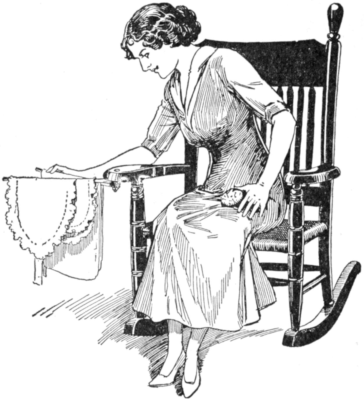
The Swinging Rack Folds under the Arm of the Chair When Not in Use
A rack like that shown in the illustration is convenient as a support for articles being sewed or repaired by the home worker. It was made by fastening two bars from a towel rack to the arm of the rocker by means of a bolt. When not in use, the bars are folded back under the arm of the chair. One of the bars may be provided with hooks so that scissors and other sewing requisites may be placed on them.—Mrs. J. E. McCoy, Philadelphia, Pa.
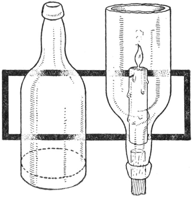
A candle may be carried in a glass bottle, as shown in the sketch, with little danger of setting fire to surrounding objects, and without permitting the melted wax to leak upon the floor. The bottom of the bottle is cut off and the candle inserted as shown, the neck affording a convenient handle.—Stanley Radcliffe, Laurel, Md.
[292]
To provide an inexpensive desk in a shop, where space was quite limited, the folding wall desk shown in the sketch was devised. It was cut from a packing box and the hinged lid built up of boards of better quality. To give a good writing surface, a piece of heavy cardboard was fastened to the writing bed with thumb tacks and may be renewed whenever necessary. The inside of the desk was fitted with filing compartments arranged to care for a large variety of shop forms and stationery. An inkwell holder made of a strip of sheet metal was fixed to the end of the desk and the bottle suspended in it, there being space for additional bottles also. The hinged lid is provided with a hasp and padlock. When not in use the desk may be tilted upward and locked against the wall with small catches. By using a T-square against the left edge of the writing bed, a convenient drafting table for shop sketching is provided.
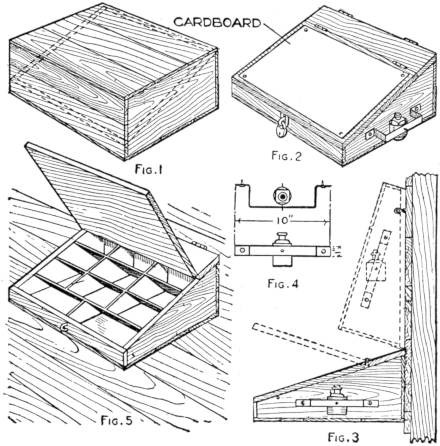
| Fig. 1 | Fig. 2 |
| Fig. 4 | |
| Fig. 5 | Fig. 3 |
The Packing Box from Which the Desk was Made is Shown in Fig. 1. The Dotted Lines Indicate Where It was Cut to Give the Slanting Writing Surface. The Device in Its Normal Position is Shown in Fig. 2; Hooked against the Wall, in Fig. 3, and with the Lid Raised, Showing the Compartments, in Fig. 5.
The detailed construction, for the making of the desk from stock lumber, by boys, or amateur workers with tools, may be carried out as follows: Determine upon the size of the proposed desk. Convenient dimensions are 30 in. long, 18 in. wide, 7 in. high at the back, and 4 in. high at the front. Use ⁷⁄₈-in. soft wood; pine and poplar are suitable. Cut and shape all the pieces before beginning the assembling of the parts. The wood should be planed smooth and may be sandpapered lightly when the construction is completed, before applying a finish. A simple arrangement of the pieces so they can be nailed together is that shown in the sketch, which was used in making the box. First shape the pieces for the sides, 5¹⁄₄ in. wide at the larger end, 2¹⁄₄ in. wide at the smaller, and 16¹⁄₄ in. long. Clamp the boards together, or tack them with two wire nails while shaping them, so that they will be exactly alike. Make a piece 5¹⁄₂ in. wide and 30 in. long for the back, and one the same length and 2¹⁄₂ in. wide for the front. Nail them to the ends, as shown, permitting the slight excess material to project over the upper edges of the sidepieces. Trim off this extra stock with a plane so that the upper surfaces of the front and back conform to the slant of the sidepieces. Make a strip 4 in. wide for the upper edge of the desk, to which the writing bed is hinged. Cut pieces for the bottom and nail them in place.
Before nailing down the upper hinge strip the interior fittings should be made. Use wood not thicker than ¹⁄₂ in., and fit the pieces into place carefully, nailing them firmly through the outer faces of the desk. A better method is to make the pigeonholes or compartments with a piece of the thin stock on the ends of the partitions, so that the compartments are built up as[293] a unit and slid into the desk, no nails being necessary to hold them.
The lid should be made of sound, dry stock and glued up of strips about 3 in. wide, to prevent it from warping or twisting easily. If the person making the desk has the necessary skill, it is best to fix a strip, 2 in. wide, at each end of the writing bed, to hold the pieces together and to keep the bed in shape.
The holder for the inkwell is made of a 1-in. strip of metal, bent to the shape shown in Fig. 4, and drilled to fit small screws. A can is supported in the holder and the bottle rests in it.
The desk may be finished by painting it or giving it a coat of shellac and one of varnish, either after it has been stained to match adjoining woodwork, or in the natural color.
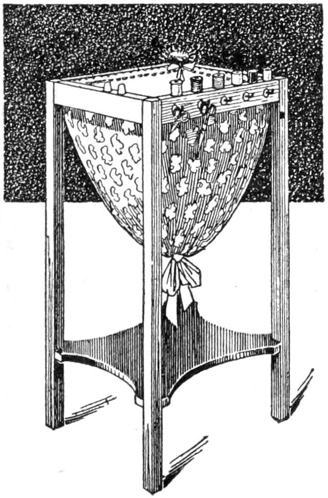
The stand shown in the sketch may be made by using part of a small table, or by building the framework especially for the purpose. It was made for use in connection with sewing and fancy work, and provides for the tools and incidental materials necessary. The stand is 28 in. high and about 15 in. square at the top. The bag built into the frame may be made of any strong, suitable material, and its color should match the finish of the wooden part. A row of nails are set in the top edge of the rails to provide for spools of thread and thimbles. Scissors and other tools are placed on the shoulder hooks fastened on the side of the rail.
¶When paper sticks to a negative during printing remove it by soaking it in the hypo bath, sacrificing the print rather than the negative.
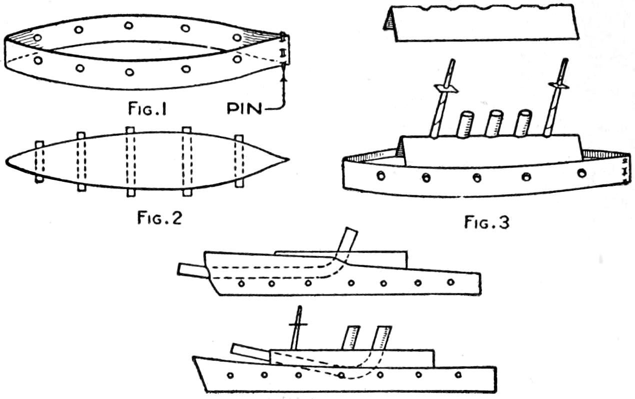
| Fig. 1 | Fig. 3 |
| Fig. 2 | |
| Fig. 4 | |
Fleets of Battleships may be Made of Paper
With a pair of scissors, pins, and a newspaper or two, a fleet of warships can be made to sail the seven seas of polished floors. Strips of paper, through which holes at opposite points have been cut, and pinned together at one end, as shown in Fig. 1, are used for the sides of the boat. Rolls of paper are slipped through the opposite holes, as shown at Fig. 2, and provide support for the deck, which is a flat piece of paper pointed at the end to fit between the sides of the craft. A second deck fitted with funnels and masts, as shown in Fig. 3, is made of a folded piece of paper with holes cut through it for the masts and funnels, which are rolls of paper. If plain paper is used, the warships may be made in several colors, which adds to the effect of rivalry between the fleets. Other types of craft may easily be devised, two of which are shown in Fig. 4. Not only the youngsters in the household, but their elders as well, may find not a little amusement and diversion in the making of a fleet of such warships, modeled after battleships, destroyers, battle cruisers, and other vessels.
A board for use in work that requires tedious kneeling, as in scrubbing, repairing of sidewalk lights, and similar work, may be made as follows: Procure a board, ⁷⁄₈ by 10 by 14 in., and pad it with a section of carpet. Place three casters under it, two being[294] set at the rear and one at the front edge. If desired, small strips may be nailed at the sides to prevent the knees from slipping off. Such a device enables the user to move along the floor easily without injuring the knees.—R. S. Matzen, Fort Collins, Colo.
An ordinary circular-wick kerosene lamp produces enough heat to do considerable cooking, provided the heat is properly utilized. A simple and practicable method of converting such a lamp into a cooker is as follows: Saw a hole, 12 in. square, in the top of a small table, or packing box of about the same height as a table. Cover this with a piece of sheet metal, having a 4-in. hole in the center. Place a 5-in. flowerpot over the hole in the metal, and plug up the hole in the bottom of the pot with fire clay or plaster of Paris. Vegetables in jars may be set around the flowerpot to cook slowly and a roast in a pan on top of it. A wooden box, or metal pail, large enough to cover the arrangement, should be placed over it. Air holes should be provided in the lower box and in the cover.
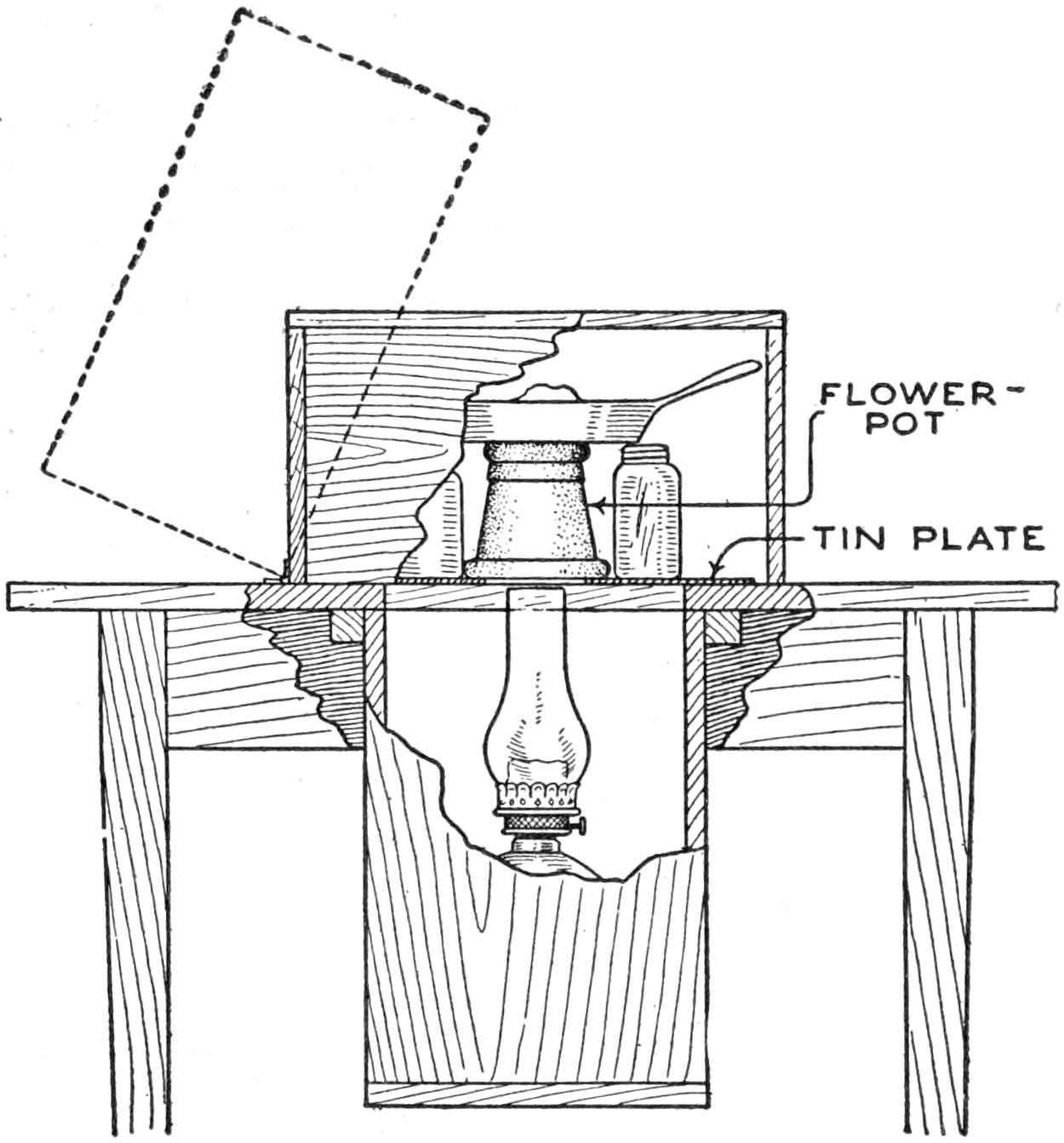
This Lamp Cooker will Prepare Meats and Vegetables Satisfactorily, and is Useful for the Camper and in Emergencies
To operate the device light the lamp and when it is burning brightly, place it under the table, elevating it so that the top of the chimney is in the center and barely within the rim of the flowerpot. Use little water in the vegetables and keep the caps loosely on the jars. The roast, if well buttered, will brown nicely, and while the cooking will require considerably more time than it would in a range, the results will be as good, if not superior. The natural juices are preserved by the slow cooking at comparatively low temperature. The cover may be lifted to turn the meat occasionally. This device will appeal to campers, summer cottagers and others.—W. W. Baldwin, New York, N. Y.
In placing a miter box on a workbench considerable space is often wasted, and the workman is obstructed. By raising the miter box on the bench mounting it upon two blocks, about 6 in. high and set back about 18 in. from the front of the bench, small space is utilized, and the tool may be used as conveniently as otherwise. The space under the miter box and the open space in front of it are available for the disposal of ordinary tools, and there is no danger of the saw striking them. By making another stand, the height of the bearing surface of the miter box, and moving this about on the bench, long pieces may be handled with ease. This stand is removed from the bench when not in use.—Henry Simon, Laguna Beach, Calif.
A device for punching identification marks in the pages of books or papers, may be made easily by setting pins into a small box filled with sealing wax. The box should be large enough to accommodate the desired wording without crowding, leaving about ¹⁄₄ in. all around the edge. Cut the box, which may be of cardboard, to a height ¹⁄₁₆ in. less than the length of a common pin. Mark the words to be punched on a piece of cardboard which just fits into the box. Punch holes along the letters and transfer them to the bottom of the[295] box. Insert pins from the outside through the bottom of the box and permit their ends to come out of the holes in the cardboard guide. Cut away enough of the guide piece so that the melted sealing wax can be poured in, setting the pins firmly. The guide piece is then removed, exposing the ends of the pins about ¹⁄₁₆ in. If the work is carefully done they will be of uniform length. Place heavy blotting paper or cardboard under the page when using the punch.—D. G. Stevenson, Chicago, Ill.
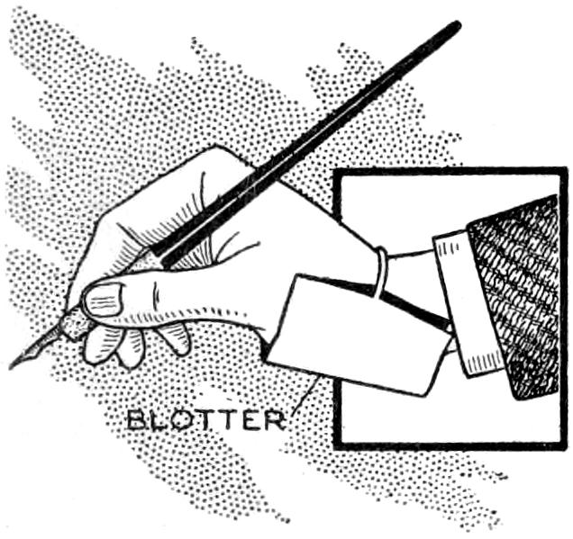
The annoyance of having to look for a misplaced blotter or to pick it up each time a signature is to be blotted, may be avoided by the use of the wrist blotter shown in the sketch. It is made by folding a piece of blotting paper, 6 in. wide and 12 in. long, into three sections. A rubber band is placed in the fold of the blotter and passed around the wrist, thus holding it in place until no longer needed. When one portion of the blotter becomes soiled, the folding may be reversed and a new surface exposed.—Frank W. Roth, Joplin, Mo.
Road maps are easily soiled and torn unless properly protected, and a satisfactory case to hold them should provide for conveniently examining the map. A piece of transparent celluloid about twice the size of the map when folded can be made into a suitable cover. Fold the celluloid into an envelope form and rivet or sew the ends, leaving the fourth edge open. The map is inserted in the cover with the desired section uppermost, affording protection and ready access at the same time.
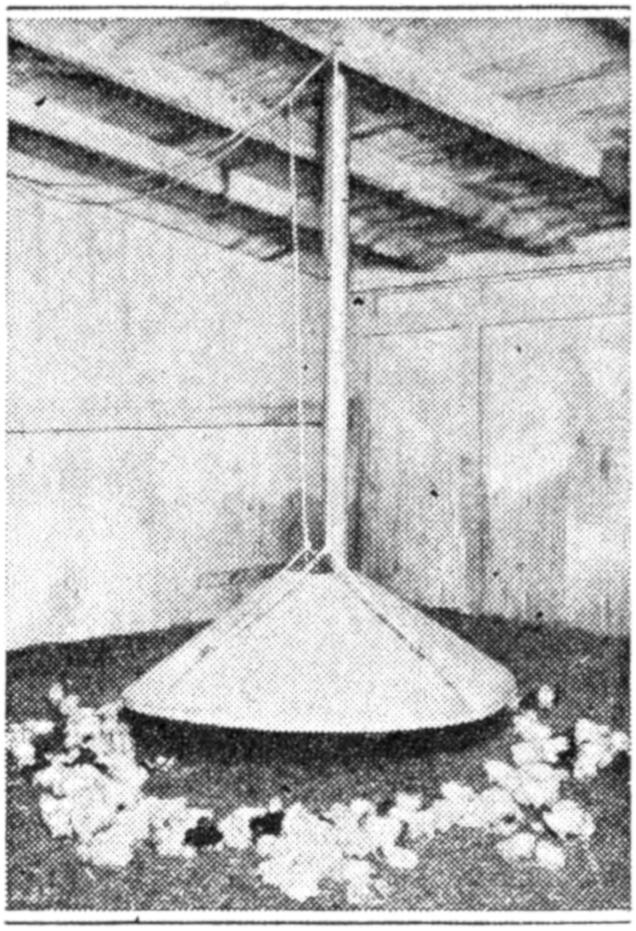
A shield of sheet metal, having a small heater in the center of it, provides a good means of warming a brooding house for small chicks. The heat is radiated from the shield and the chicks remain at a distance, seeking a comfortable temperature. The device may be made easily by cutting a sheet of metal to form a cone-shaped hood and fitting it with a vent passing out through the roof of the house.—Samuel S. Snelbaker, York, Pa.
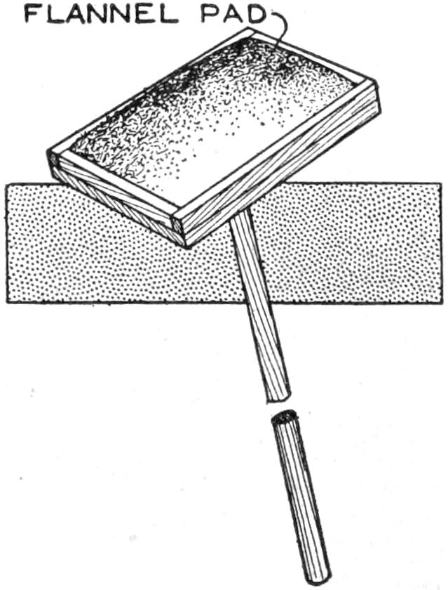
Removing old wall paper, particularly from the ceiling of a room, is a disagreeable task at best, and the device shown in the sketch aids in the process. A board, about 15 in. long and 12 in. wide, was provided with strips at its edges and a pad of flannel was fitted into it. The device is used by moistening the pad and applying it to the wall paper. The paper is loosened thoroughly and may be removed in pieces of considerable size. This method has been found much quicker than that of soaking the paper with a moistened brush.—J. H. Moore, Hamilton, Canada.
¶A clay pipe may be used as a crucible for melting small quantities of metal. The stem is broken off and a plug fitted into it.
[296]
Practical use as well as the novelty of its construction makes the trinket case shown in the illustration well worth the time and effort necessary to make it. Various kinds of wood—preferably of the better cabinet varieties—are suited to the design shown, which was made of ³⁄₁₆-in. stock, like that used in cigar boxes. The size shown is that of a bound volume of a magazine like Popular Mechanics, and may be adapted to special needs. The back and the cover slide in grooves, which are not visible when the “book” is closed, making it difficult and interesting for one to discover how the case is opened. The back may be marked and lettered to resemble a bound volume closely, and if special secrecy is desired, it may even be covered with leather, in exact duplication of those on a bound set of magazines kept in the bookcase with it.
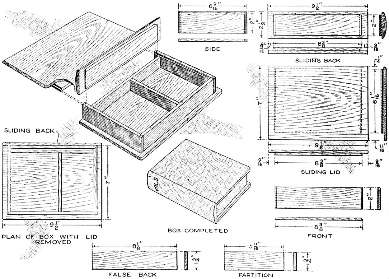
This Trinket Case Is a Practical Novelty That may be Used as a Secret Container to be Set on the Bookshelf with Similar Bound Volume
Make the pieces for the frame of the box first. If possible, make one strip of the proper width—2 in., in this case—and long enough for the two ends and the front. Make another strip 1³⁄₄ in. wide and long enough for the partition and false back of the tray. Cut these to the lengths indicated in the detailed sketches of the parts. Mark out the grooves in the end pieces carefully and cut them with a saw that cuts a groove ³⁄₃₂ in. wide. The grooves may be cut by clamping a straight strip of wood on the surface of the ends the proper distance from the top, and sawing cautiously along the strip to the proper depth. The grooves across the grain may be cut similarly, or in a miter box.
Glue the pieces of the frame together, taking care that the corners are square. If necessary, place blocks inside to insure that the clamping will[297] not disturb the right angles of the box. Shape the bottom and cover pieces nearly to the final size before gluing them; then, if small nicks are made in the edge, they may be removed by a cut of the plane, when the case is complete. Glue the sliding pieces to the cover and to the back. This must be done carefully, and it is convenient to drive small brads part way into the second piece, from the inner side, to prevent the pieces from slipping while being glued. If proper care is taken, only a small amount of glue will be forced out, and this can be removed with a chisel when dry. The edges may be trimmed off to their exact size, and the entire construction given a final light sandpapering. It is then ready for the stain and shellac, or other finish. The parts that slide in grooves should not be shellacked or varnished, because this is apt to cause them to stick.
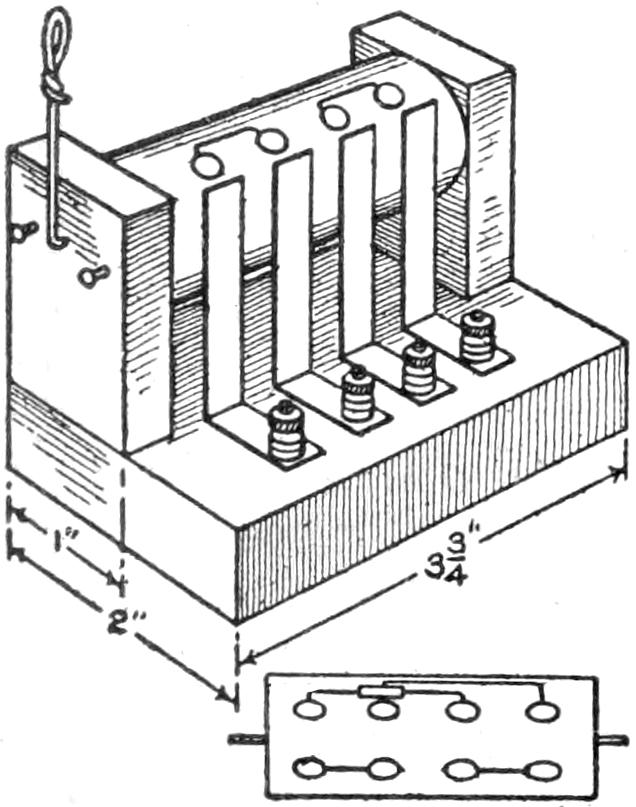
A cylinder reversing switch for small battery motors may be constructed cheaply, from a 3-in. length of broom handle and ¹⁄₂-in. boards, as shown. The four brushes are strips of copper. The contacts on the moving cylinder are eight brass tacks, connected as indicated in the diagram. The wires are insulated with paper where they cross. The handle is of heavy wire, and two tacks limit its motion, as shown. The method of connecting the switch is as follows, for either a series or shunt motor: Remove the two wires from the motor brushes, and connect the two middle brushes of the switch to the motor brushes. Connect the wires removed from the motor brushes to the outer brushes of the switch.—Claude Schuder, Sumner, Ill.
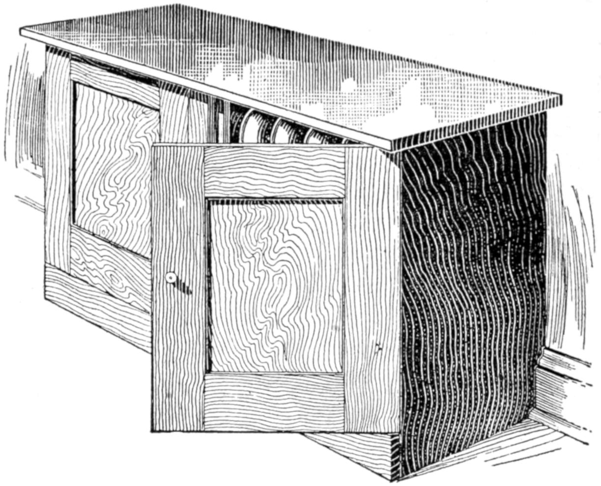
This Radiator Cover is Built so That Shelves may be Inserted Quickly for Use as a Cabinet
Because of the accumulation of dust on a kitchen radiator in the summer, a cupboard was built over it, and used at other seasons of the year for the storage of various articles, by fitting it with shelves. While in use as a radiator cover, the top of the cupboard provided a convenient seat. If properly made, cabinets of this type can be used in other parts of the home to advantage.
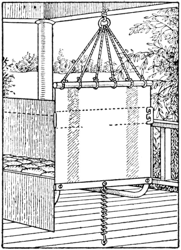
It is often necessary to hang swinging porch seats fairly close to surrounding woodwork, which is marred by their swinging too far. To overcome this, procure a coil screen-door spring and cut it in two. Bend a hook on each cut end, and fasten one of the springs to the center of each end of the swing, and to the floor. This permits only gentle swinging.—F. C. Hayes, Niagara Falls, Canada.
¶Proper ventilation of cellars makes it desirable to provide a screen door on the cellar entrance.
[298]
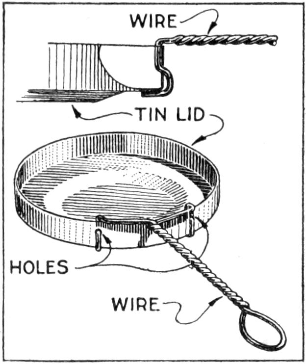
If you want an egg done to perfection try the frying pan made of a tin cover. It was intended for emergency use only, but proved so satisfactory that I kept it as a regular fixture. The wire handle was fitted to the rim through two holes, as shown and hooks under the bottom of the pan, the twisting of the wires giving the required strength.
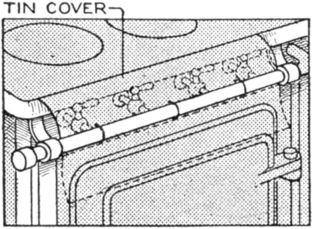
In order to safeguard the valves of a kitchen gas stove with which children might occasionally meddle, I fitted a sheet-metal cover over the valves as shown in the sketch. The cover is wired to the feed pipe and is swung forward, as indicated by the dotted outline, when not in use. Small catches may be fixed at each end of the cover, if desired.—Leroy Schenck, Mount Vernon, N. Y.
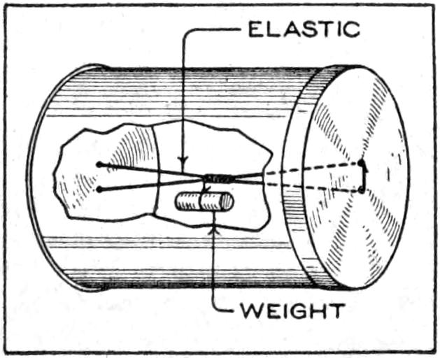
An interesting toy may be made by fitting a rubber band into a tin can and weighting it as shown. When the can is rolled on the floor it will return to its original place by reason of the weight which is supported on a string at the middle of the rubber band. The latter is passed through two holes at each end of the can, and when the can is rolled along the floor the elastic is wound at the middle. The weight reverses the direction of rolling.—Albert French, Hamilton, Ontario, Can.
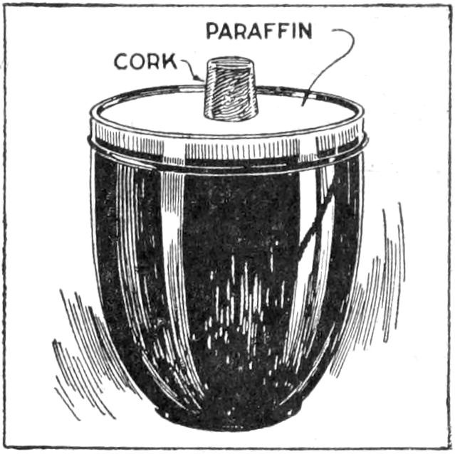
To remove paraffin from the tops of glasses or jars of preserves, without getting bits of the covering into the contents, is difficult. When pouring the melted paraffin over the top, put a small cork in the center and let the paraffin harden around it, as shown. To remove the covering, dip the top of the glass in hot water. This sealing can be used again by placing it on the top of hot jelly, the paraffin melting and adhering to the glass.—J. E. McCoy, Philadelphia, Pennsylvania.
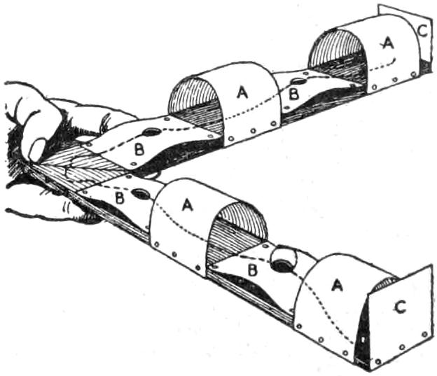
The object of this game is to pass a marble from one end to the other of the “roadway,” under the “bridges,” and over the “inclines,” without dropping it. A stop must be made at each hole. The device is made as follows: Cut two pieces of wood, ¹⁄₄ by 1³⁄₄ by 12 in., and join them to form a right angle. Cut pieces of cardboard, 4 each, 1³⁄₄ by 2¹⁄₂ in. wide, with a ³⁄₄-in. hole in the center, for inclines B, and 1³⁄₄ by 3 in., for bridges A; also two pieces 1³⁄₄ in. square for stops C. Fasten them with tacks as shown. The marble should be large enough so that it will rest in the holes at B.
[299]

Decorative Toys and Boxes
Made at Home
By Bonnie E. Snow
Homemade toys and gifts, as well as the “treasure boxes” in which they are contained, have an added interest both to the one making and the one receiving them. The holiday season makes this work especially attractive, which affords opportunity for individuality in construction and design limited only by the skill of the worker. The decorated toys and the box described in detail in this article are suggestive only, and may be adapted to a large variety of forms and designs. The gorgeously colored parrot and the gayly caparisoned rider and horse suggest a host of bird and animal forms, those having possibilities for attractive coloring being most desirable. The decorated box shown in Fig. 7 may be adapted as a gift box, to be used where its decoration may be seen, in the nursery, for example, and may be made in many forms, in fact as various as cardboard boxes are. Plant, animal, or geometrical forms may be used to work out designs, and appropriate color schemes applied to them. A good plan in determining upon a color scheme is to use the colors of the flower or other motif. If the design is not associated with objects having varied colors—a geometrical design, for instance—harmonious colors should be chosen. These may be bright and contrasting, as red and green, violet and orange, or subdued in tone.
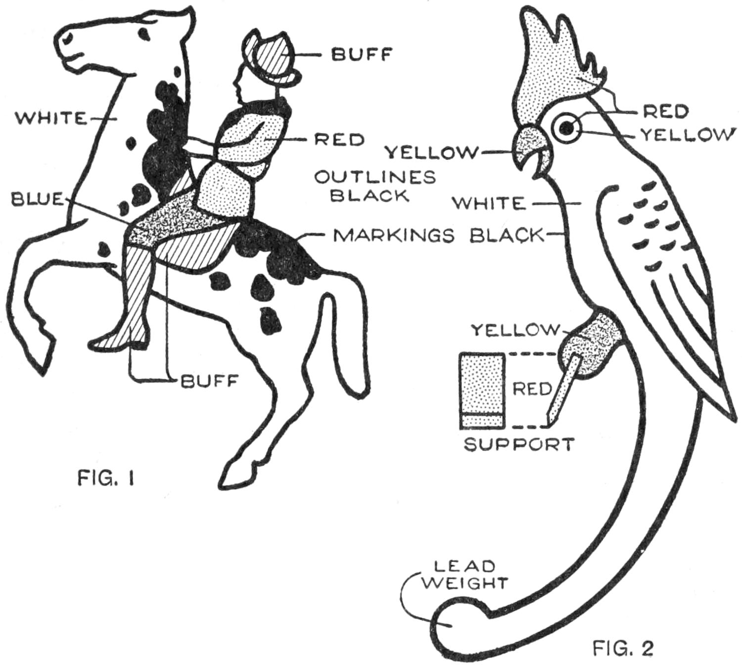
FIG. 1 FIG. 2
The Outlines for the Horse and Rider and the Parrot may be Made by Enlarging These Sketches. The Color Scheme Indicated is Suggestive Only and may be Varied to Suit Individual Taste
A design for a horse and rider, brightly colored, is shown in Fig. 1. The form is cut out of thin wood, the color applied, and the figure mounted on the curved wire, weighted at one end, as shown in Fig. 6. The toy adds a touch of color and novelty to a room, when suspended from the corner of the mantel, from a shelf, or other suitable place. Balanced in a striking attitude, forefeet upraised, even grown-ups can hardly resist tipping the rider to see his mount rear still higher. The parrot shown in Fig. 2 is made similarly, and is weighted at the end of the tail. The point of balance is at the feet, which may be fastened to a trapeze, or be arranged to perch on a convenient place, like that suited to the horse and rider.
The tools and equipment necessary for the making of such toys are simple, and available in most boys’ workshops or tool chests. A coping saw, like that shown at A, Fig. 3, is suitable for cutting[300] the wood. A fretsaw, operated by hand, foot or power, may be used, and such a tool makes this work quite rapid. To use the coping saw to the best advantage, particularly if the work is to be done on a table which must not be marred, a sawing board should be made. In its simplest form, this consists of a board, as shown at B, about ⁷⁄₈ in. thick, 3¹⁄₂ in. wide, and 6 in. long, with one end notched. This is clamped to the end of the table, as at D, with a clamp, an iron one of the type shown at C being satisfactory. Another form of sawing table especially useful when it is desired to stand up at the work, is shown at E in detail and clamped in the vise at F. It consists of a notched board, 3¹⁄₂ in. wide, fixed at right angles to a board of similar width, 11 in. long, and braced at the joint with a block about 1³⁄₈ in. square. In using the coping saw with either of these saw tables, the wood is held down on the support, as shown in Fig. 5, and the saw drawn downward for each cutting stroke, thus tending to hold the board more firmly against the saw table. It is, of course, important that the saw be inserted in the coping-saw frame with the teeth pointing toward the handle, so that the method of cutting described may be followed. The wood must be sawed slowly, especially at the beginning of a cut. The operator soon learns the kinks in handling the saw and wood to the best advantage, and can then make rapid progress.
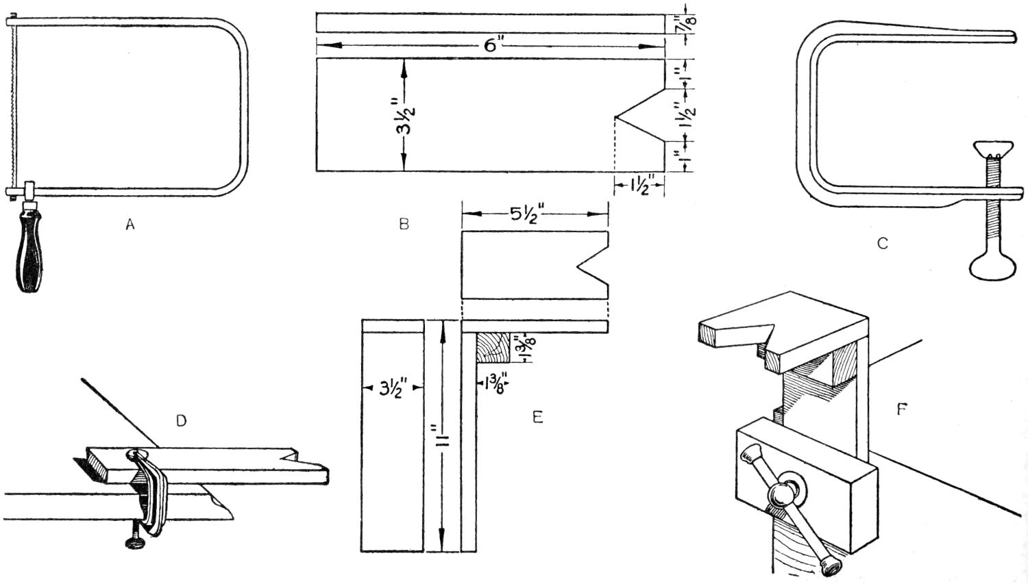
A B C
D E F
FIG. 3
The Tools Required are Found in Most Boys’ Workshops, and a Satisfactory Saw Table may
be Made Easily, as Shown in Detail
An outline drawing of the form to be cut out of the wood must first be made, to the exact size that the object is to be. There is much satisfaction if working out the form of the animal or other figure, especially for the boy or girl who has the time necessary to do good work. If desired, the figure may be traced from a picture obtained from a book, magazine, or other source. Cut a piece of wood to the size required for the design, and place a sheet of carbon paper over it; or if none is available, rub a sheet of paper with a soft pencil, and use this as a carbon paper, the side covered with the lead being placed next to the wood. The carbon paper and the sheet bearing the design should then be held in place on the wood with thumb tacks, or pins, and the transfer made with a pencil, as shown in Fig. 4. The design should be placed on the wood so that the weaker parts, such as the legs of the horse, will extend with the length instead of across the grain of the wood.[301] In some instances, where a complicated form is cut out, it is necessary to use wood of several plies, and where this is available it is worth while to use it for all of this work. For smaller objects wood ³⁄₁₆ in. thick is suitable, and stock up to ¹⁄₂ in. in thickness may be used. Whitewood, basswood, poplar and other soft, smooth-grained woods are suitable.
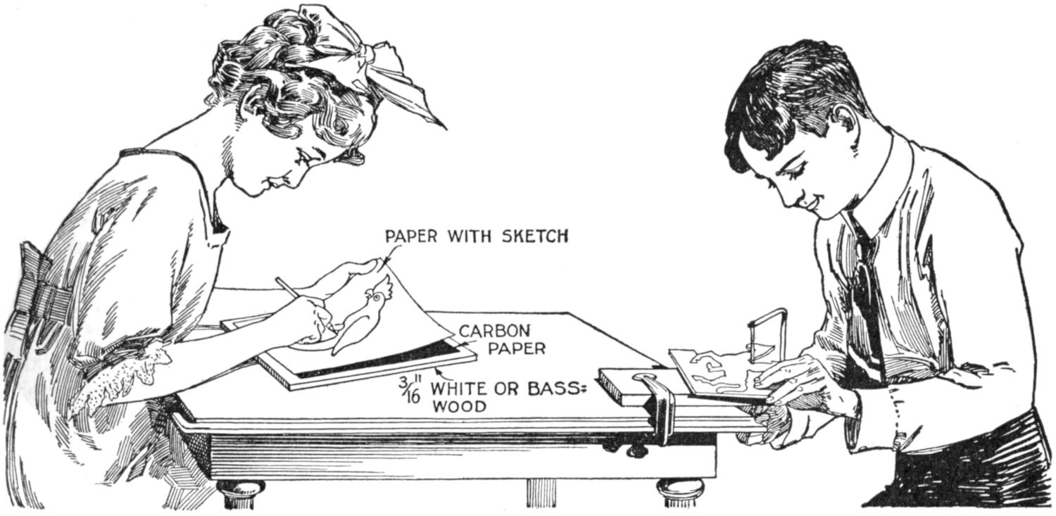
FIG. 4
FIG. 5
The Design is Traced Carefully onto the Wood and Then Cut Out with the Coping Saw, on the Saw Table
When the design has been outlined satisfactorily, place the piece of wood on the saw table with the design on the upper side. Holding the wood down firmly, as shown in Fig. 5, and sawing in the notch of the saw table, cut into the edge slowly. Apply light pressure on the downstroke only, as the upstroke is not intended to cut, and turn the piece to keep the saw on the line and in the notch. It is important that the saw be held vertically so that the edge of the cut-out portion will be square. With proper care and a little practice, the edges may be cut so smoothly that only a light sandpapering will be required to produce a smooth edge. When the figure has been cut out, smooth the edges by trimming them carefully with a sharp knife, if necessary, and sandpaper them lightly to remove sharp corners. A fine sandpaper, about No. ¹⁄₂, is suitable for this purpose. The figure is then ready for painting. The white is put on first and the other colors applied over it, when dry.
Oil paints may be used, and a varnish or shellac applied over them to give a high grade of work, but this process requires much care, considerable skill, and long drying between coats to prevent “runs” in the colors.
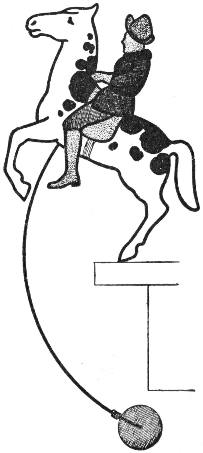
FIG. 6
Water-color paint, which can be purchased in powder form at paint stores, mixed with water to the consistency of cream is a satisfactory coloring material, and is easy to apply. Five cents’ worth of each of the colors used—yellow, red, blue, black, and white—will be sufficient for several toys. Mix each color in a separate saucer, and use a small water-color brush to apply the paint. In painting the horse and[302] rider, the horse is first painted entirely white, and then the black spots are applied after the color is dry. The rider’s coat is painted red; the trousers blue; the hat and leggings buff, as indicated in Fig. 1. Mix a brushful of yellow with a brushful of red, and add about three brushfuls of white. A half brushful of black may be added to dull the color, if desired. The flesh tone for the rider’s face is made by mixing a little red with white. When the colors are dry, all edges are outlined with a heavy line of black, not less than ¹⁄₈ in. in width. This outline may be evenly applied with the point of the brush.
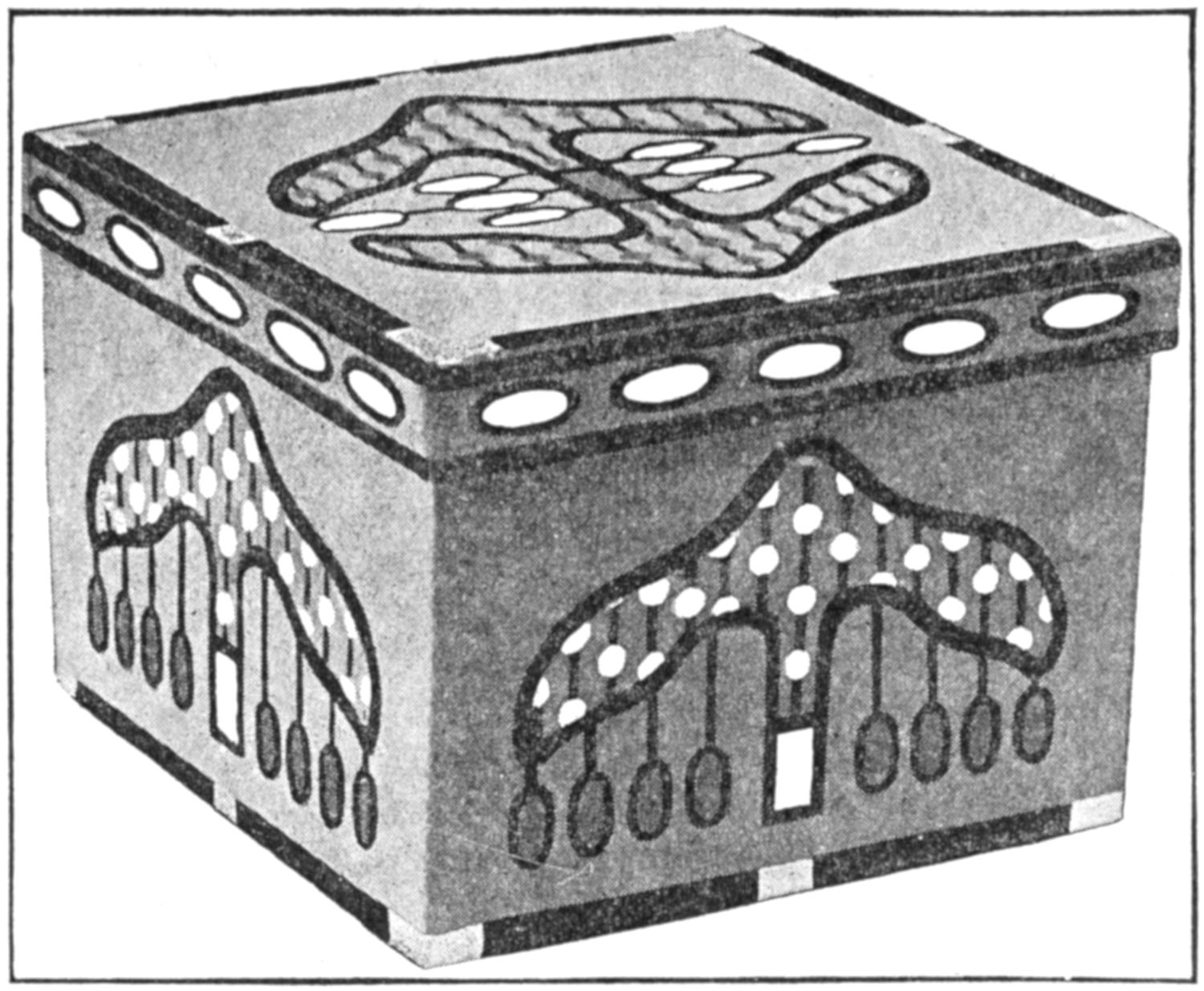
FIG. 7
A Handmade Box Is Interesting in that It Expresses the Individuality
of the Maker, Especially When Made as a Gift
The method of making the parrot is similar to that described for the horse and rider, and the color scheme is suggested in Fig. 2.
It will be noticed that no attempt is made to secure a lifelike, or realistic, effect in painting these toy shapes. All colors are flat, that is, without light and shade. The toys are really decorative designs, and the maker is at liberty to use any colors desired, whether natural or not.
The horse and rider is balanced on the hind foot, as shown in Fig. 6, by using a lead weight, attached to a ¹⁄₁₆-in. wire, as a counterweight. The wire should be set into the body of the horse, behind the foreleg, to a depth of ³⁄₄ in. The weight of the metal and the curve of the wire should be adjusted to obtain the proper balance. The parrot is balanced in the same way, except that the weight is fixed to the end of the tail, which is curved like the wire.
These and other homemade toys or gifts may be sent or contained appropriately in boxes decorated to match them, as shown in Fig. 7. They may be made complete, or commercial boxes of suitable sizes may be covered and decorated. If good materials are used, such a box makes a pretty and useful gift in itself. The complete process of making a typical box is described for those who prefer to make one of special size. The dimensions given are thus only suggestive, and may be adapted to suit particular needs.
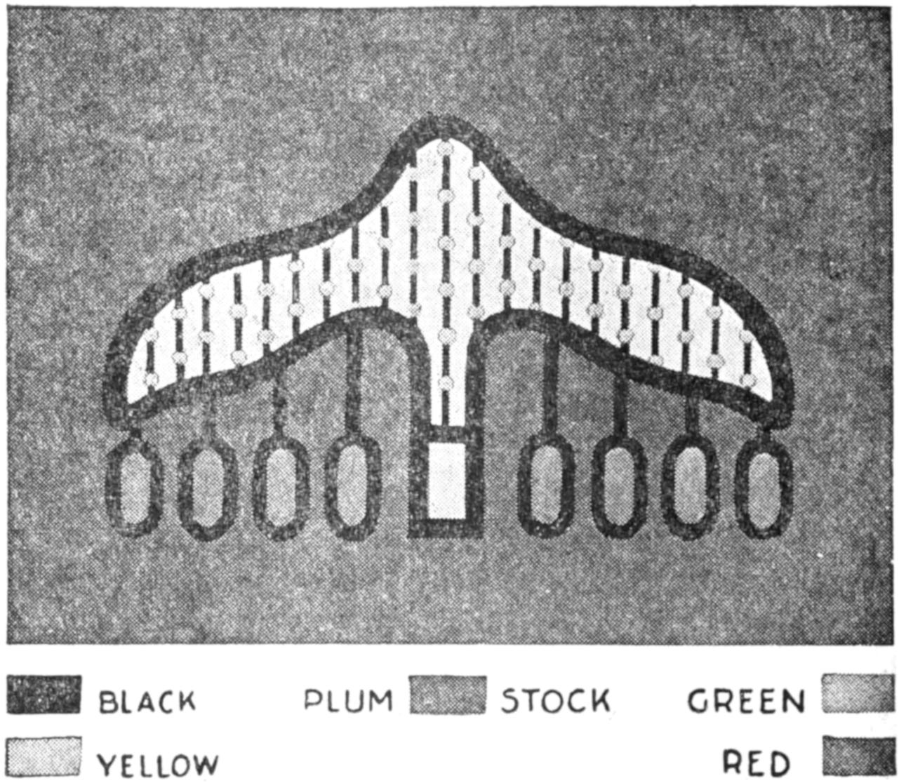
FIG. 8
Color Schemes may be Obtained from Flowers and Other Natural Forms, or by Selecting a Combination of Harmonious Shades. The Background Is of Plum-Colored Paper; the Small Circles are Emerald-Green; the Light Area, Yellow, and the Ovals, Orange-Red
The materials necessary are: cardboard, cover paper, lining paper, bond paper, paste, and water colors. The latter should be of the opaque variety since white or other light shades may then be used on darker-colored paper. A sharp knife, a scissors, a metal-edge ruler, and bookbinder’s paste are also needed. Suitable substitutes for the[303] various kinds of paper may usually be obtained in the home, if they are not readily available at local stationery stores or printing establishments.
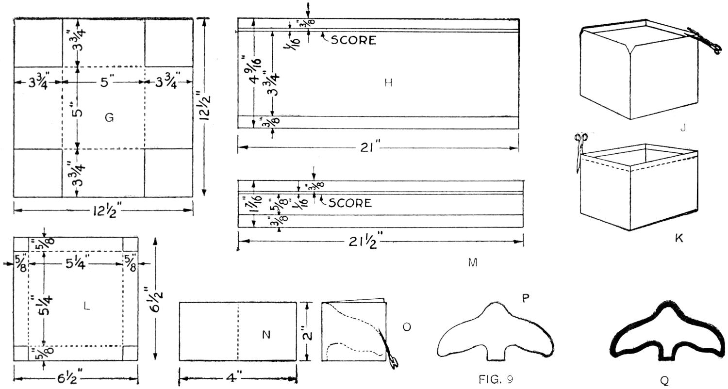
| G | H | J | ||
| M | K | |||
| L | N | O | P | Q |
FIG. 9
The Various Steps in the Process of Making and Covering a Rectangular Cardboard Box are Shown in Detail.
The Method of Making a Pattern for the Design is shown Below
The box is made as follows: Determine upon the proper size and select materials to carry out the design. An appropriate combination of colors and materials is suggested in Fig. 8. Cut out a square of the cardboard, having sides 12¹⁄₂ in. long, as shown in Fig. 9, at G, then mark it as indicated and cut on the full line to remove the square corners. Crease it on the dotted lines and fold to form a box. To hold the cardboard in box shape, strips of bond paper—ordinary writing paper—are cut, 3³⁄₄ in. long and 1 in. wide, then creased along their centers and pasted to the corners. The paste should be applied to the paper strip first, then on the corners of the box. Apply the piece of paper over the corner of the box on the outside, pressing it to make a snug fit. Repeat this operation on the other corners.
Lay off the dimensions given at H on the selected color of cover paper, which in this instance is plum, and score the lines indicated. Spread paste smoothly over the surface of the plum paper, between the lines drawn ³⁄₈ in. from the long edges, and then spread a thin layer of paste over the outer surface of one of the sides of the box. Apply the paper to the pasted surface and press it down, rubbing gently out from the center to remove air bubbles. Fold the ³⁄₈-in. laps at the top and bottom over the upper edge of the box and around the lower corner. Repeat this process, covering the four sides. To form a smooth fold at the corners, it is best to miter the paper as shown at J and K, before pasting it down. Then paste a square of the same paper 4⁷⁄₈ in. wide on the bottom of the box, taking care to match the edges evenly all around.
Line the box with a strip of lining paper, 20 in. long and 4 in. wide. Try the lining by folding it into the box so that its upper edge is about ¹⁄₈ in. from the edge of the box, and crease it carefully into the corners. Remove it, apply paste, and press it well into the corners when pasting it down. Paste a square of the same paper, 4⁷⁄₈ in wide, in the bottom of the box.
The cover is made by the same process as the main portion of the box. The dimensions of the cardboard are shown at L, and the covering at M. It should be observed that the cover is slightly[304] wider than the box, so that it will fit easily.
When the box is thoroughly dry, it is ready to receive the decorations on the top and sides. The design may be adapted from a leaf, flower, or similar form, as well as from geometric or animal forms. The horse and rider, the parrot, and the animals shown in the headpiece of this article are all suggestive of animal forms that are available.
The design shown on the box in Fig. 7 was adapted from a flower form, two of the units being joined for the decoration on the top. To obtain a pattern for the design, fold a piece of paper, 2 by 4 in., as shown at N, and outline one-half of a leaf, flower or similar motif. Cut the folded paper as at O, and a pattern similar to that shown at P results. Trace around this to place the figure on the box. Outline the figure with black, about ¹⁄₈ in. wide, as at Q. The oval figures, suggestive of small pods on a flower, are also outlined in black, and joined to the main portion of the design by a black line. Thinner black lines are drawn vertically across the form, and small circles placed along them at intervals. The color scheme is shown in Fig. 8. The light background is yellow, the small circles are emerald-green, and the ovals red-orange. The rim of the cover is decorated with a border of white ovals, outlined in black. The corners are banded in black and white as shown in Fig. 7.
A slovenly sportsman misses much of the joy of the man who takes pride in giving his outfit the proper care, not only during its period of use, but also during the winter, when occasional overhauling serves to keep one in touch with sports of other seasons. And a very real joy it is, each article recalling an experience as one examines it minutely for a possible rust spot, scratch, or injury.
Tents usually come in for much abuse, which shortens their life considerably. Cotton duck molds quickly, and rots if left rolled up damp. Care should be taken, therefore, to insure its perfect dryness before storing. Silk and silk-composition tents, being thoroughly waterproof, are almost as dry after a rain or dew as before, so may be packed for moving at any time. But all tents and tarpaulins should be washed and dried carefully after the season’s use.
Blankets absorb much moisture, and should be shaken and spread out over bushes to dry in the sun, at least once a week. In the cold nights of late summer, the increased warmth of blankets after drying is considerable.
Pack straps and ropes should not be left exposed to the weather. They speedily become hard or brittle; squirrels like the salt they can obtain by chewing the leather, and if left on the ground in a rabbit country, the straps are soon cut into bits. Hang the leather goods in the peak of the tent, keep them away from fire, and oil them occasionally.
A canoe should not be left in the water overnight, or at any time when it is not in use. Simply because use makes it wet, a canoe should not be left so any more than a gun should be left dirty, or an ax dull. If on a cruise with a heavy load, pile the stuff on shore at the night camp, and turn the canoe over it. If a canoe is permitted to remain in the water unnecessarily, or its inside exposed to rain, it soon becomes water-soaked and heavy for portage, besides drying out when exposed to the sun, and developing leaks.
Small punctures in the bottom of a canoe may be mended with spruce, tamarack, or pine gum, melted into place with a glowing firebrand, held close, while blowing at the spot to be repaired. Torn rags of canvas-covered bottoms may be glued with the softer gum of new “blazes,” gathered with a knife or flat stick.
While traveling on shallow streams the bottom of a board canoe develops a “fur” of rubbed-up shreds. Every[305] night these should be cut short with a sharp-pointed knife, to prevent a shred from pulling out and developing into a large splinter. The paddles, and the setting pole, unless shod with iron, become burred at the ends and require trimming down to solid wood.
The track line, if in use, is wet most of the time, and unless dried frequently, becomes rotten. Every tracker knows the grave danger with a rotten line in a rapids.
During the winter the canoe should be scraped and sandpapered, bulges nailed down, permanent repairs made to the covering, and the canoe painted on the exterior and varnished on the interior.
The average fisherman is an enthusiast who needs no urging in the matter of caring for his outfit, and the user of firearms should profit by this example. Even if not a shot has been fired from a gun all day, moisture from the hands, or from the dampness in the woods, or marshes, may cause rust spots, or corrode the bore. Rub an oily rag through the bore and over the outside of the gun every evening, before laying it aside.
Cleaning rods are safer and more thorough in cleaning the bore than the common mouse string, which may break when drawing a heavy piece of cloth through, causing much difficulty. A wooden rod, preferably of hickory, is best, although the metal rod is stronger for use in small bores, but care must be taken not to wear the muzzle unduly. The hunting weapons should be carefully overhauled before storing them, and given a coat of oil to protect the metal parts from rust.—A. M. Parker, Edmonton, Can.
Mention of periscopes is quite common in the reports from European battle fields; such a device in a simple form can be made easily by boys who have fair skill with tools. The illustration shows a periscope which may be used for play, and has other practical uses as well. In a store or other place where a person on duty cannot watch all parts of the establishment, such a device is convenient in that it will reflect persons entering the door. As a toy or for experimental purposes the periscope shown has many possibilities, and will appeal to youngsters.
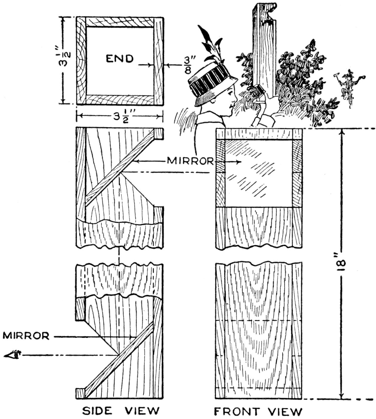
This Simple Periscope Is Useful Both for Play and Practical Purposes
It consists of a square box, 18 in. long, open at the ends. It is 3¹⁄₂ in. wide and made of wood, ³⁄₈ in. thick. A mirror is fitted at an angle of 45° near one end of the box or tube, as shown in the sketch. The front of the mirror is opposite a three-cornered opening in the box which extends across one side. The opposite end of the tube is also fitted with a mirror in the same manner, except that the front of the mirror faces to the opposite side of the box at which there is also an opening. In using this device, the user sights from the point indicated by the eye. The image is reflected in the mirror at the top and thrown onto the lower mirror, where it may be seen without exposing the head above the level of the lower opening. It is this application of reflection by mirrors that makes it possible for soldiers to see distant objects without exposing themselves to fire, by the use of the periscope.
[306]
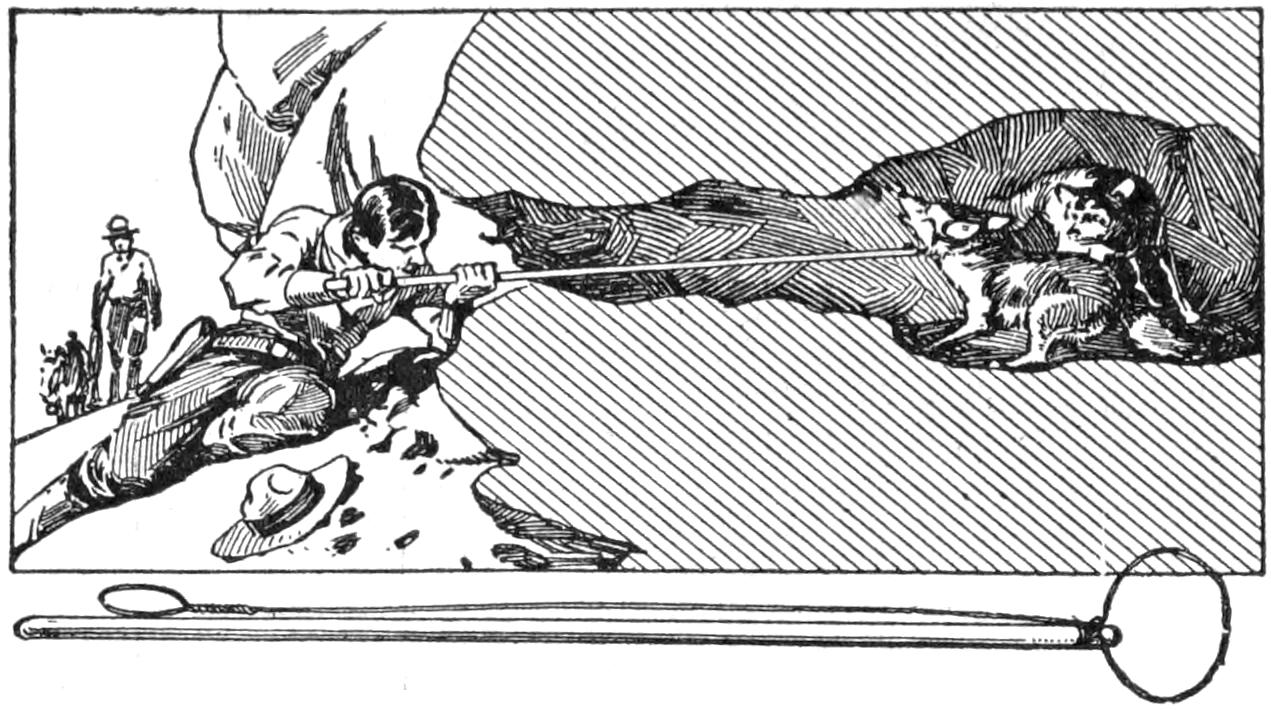
By Drawing on the Wire the Coyotes were Brought under Control and Forced from Their Lair
Two coyotes, resisting capture in a hole under a lava ledge, were hauled forth quickly when the device shown in the sketch was used, after other means had proved ineffective.
I made a snare of baling wire and attached it to a pole, 6 ft. long, running the wire down from the loop to the end of the handle. The loop was made about twice the size of the coyote’s head, and, by drawing on the wire at the handle, the animals were placed under control and held at a safe distance.—Contributed by Milton Barth, Geyserville, Cal.
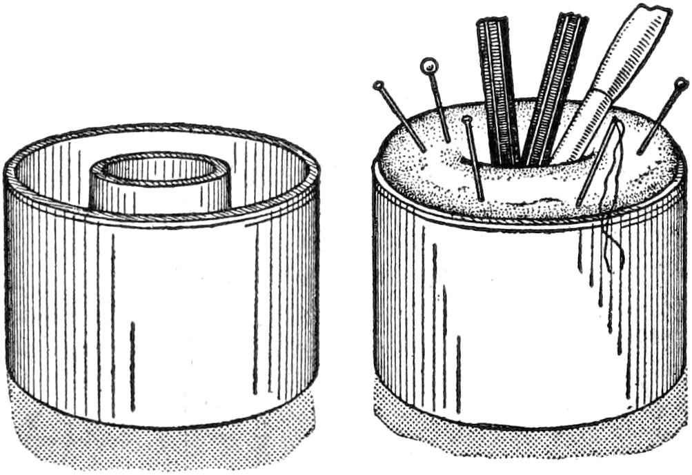
A Pincushion Built to Fit the Empty Paste Compartment Makes a Useful Article of the Paste Pot
The type of paste pot that contains a central well to hold the paste brush is not always cast aside when empty. A pincushion built to fit the outer ring, or paste-holding section, is added and the brush holder is used to hold pens and pencils.
¶A magnet may be used to advantage in picking up tacks or small nails which have been scattered on a floor.
Black walnut, or mahogany, is the most effective wood to use in making this simple but artistic frame. It requires a very small amount of stock and what is used should be of a good quality and carefully worked to the given dimensions with keen tools. The stock required for the frame is as follows:
| Black walnut, or mahogany: | |
| 2 | pieces, 27¹⁄₂ in. long, 1³⁄₈ in. wide, and ³⁄₄ in. thick. |
| 1 | piece, 22 in. long, 1³⁄₈ in. wide, and ³⁄₄ in. thick. |
| 1 | piece 9¹⁄₄ in. long, 1³⁄₈ in. wide and ¹⁄₄ in. thick. |
| White holly: | |
| 1 | piece, 27¹⁄₂ in. long, 1¹⁄₂ in. wide, and ¹⁄₁₆ in. thick. |
| Picture board: | |
| 1 | piece, 25 in. long, 9 in. wide, and ¹⁄₈ in. thick. |
The dimensions for the walnut or mahogany pieces are rough sizes, oversize to allow for the planing to the dimensions given in the sketch. The white holly may be procured smoothly planed on both sides and of the exact thickness required. The picture backing may be purchased in almost any store that sells frames. It is usually rough pine and inexpensive.
The first operation is to plane the frame pieces on one side and edge, using great care to insure both being perfectly straight and the edge square with the face. Gauge for, and plane to the thickness required, although this need not be exactly ⁵⁄₈ in. as called for, but if the stock will stand ¹¹⁄₁₆ in. or ³⁄₄ in. do not take the time to cut it down to ⁵⁄₈ in. The little cross rail must be exactly ¹⁄₈ in. thick, as it is to be let ¹⁄₈ in. into the rabbet cut for the glass, which makes it come ¹⁄₈ in. back from the face of the frame when it is in place. Plane all of these pieces to the width, 1¹⁄₈ inch.
For cutting the rabbet, a plow, or a ³⁄₄-in. grooving, plane is the best tool to use, but if neither is available a rabbet plane can be used. Be sure to plane the rabbet square and to the lines gauged for the depth and width.
To groove the pieces for the holly strips a special tool is required. This may be made of a piece of soft sheet[307] steel or iron, which must be of a thickness to correspond to that of the holly. A piece 2¹⁄₂ in. long, and of almost any width, will answer the purpose. File one edge of the metal straight, and cut saw teeth in it by filing straight across with a small saw file. Remove the burr raised by the filing by rubbing each side on an oilstone. Drill two holes in it for fastening with screws to a piece of hard wood. The wood serves as a fence, and if properly fastened to the metal, the teeth should cut a groove ¹⁄₁₆ in. deep and ³⁄₁₆ in. from the edge. The holly strip should fit the groove tightly so that it can be driven home with light taps of a hammer. It is well to try the tool on a bit of waste wood first to see if it cuts the groove properly.
The holly is cut into strips, ¹⁄₈ in. wide with a slitting gauge. An ordinary marking gauge, with the spur filed flat on each side to make a sharp, deep line, will do very well for this work. The gauging is done from both sides of the piece to make the spur cut halfway through from each side. Before the slitting is attempted, one edge of the piece is first straightened. This is readily accomplished with a fore plane, laid on its side and used as a shoot plane. The strip to be planed is laid flat on a piece of ⁷⁄₈-in. stock with one edge projecting slightly. This raises it above the bench and allows the fore plane to be worked against the projecting edge.
The strips should be applied to the groove to test the fit, and if found to be tight, they must be tapered slightly by filing or scraping the sides. If the fit is good, hot glue may be run into the grooves with a sharp stick, and the strips driven into place. They will project above the surface slightly, but no attempt should be made to plane them off flush until the glue has become thoroughly hardened; then use a sharp plane, and finish with a scraper and No. 00 sandpaper.
The miters are cut in a miter box, or planed to the exact 45° angle on a miter shoot board. Before gluing the corners, the recesses are cut for the cross rail, but it must not be put in place until the corners of the frame have been fastened and the glue given time to dry.
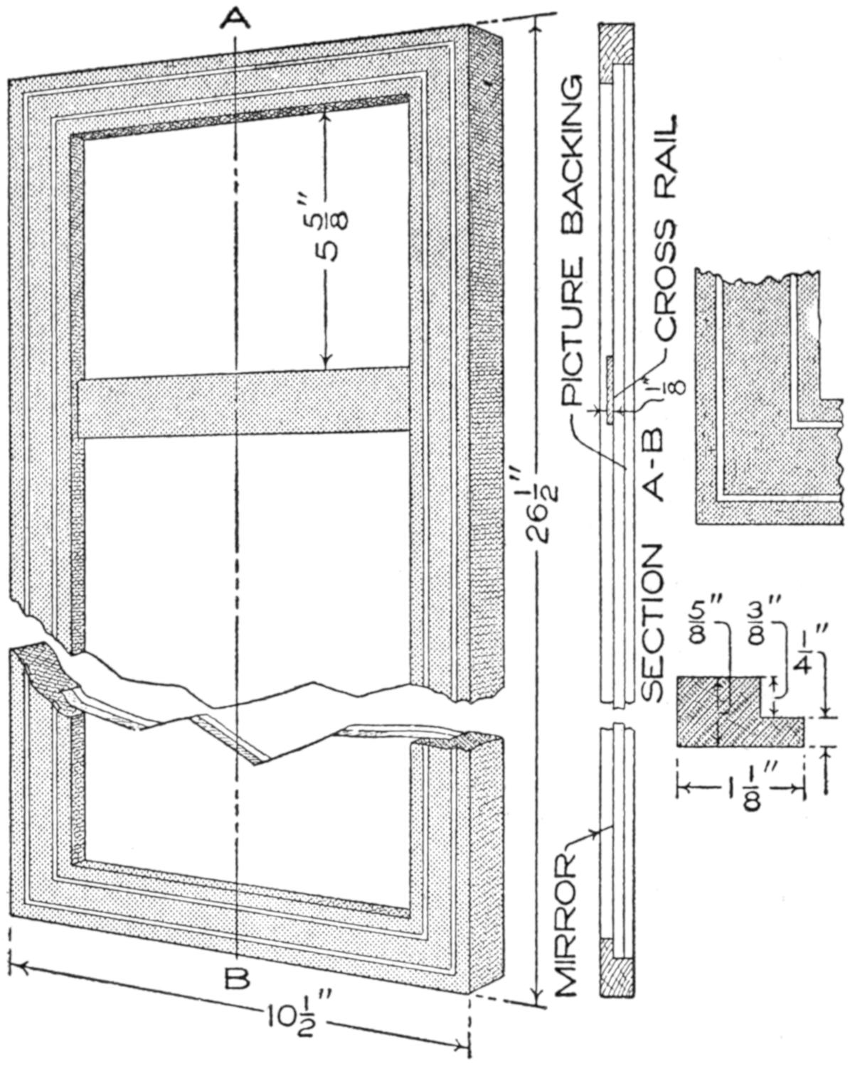
An Inlay of Holly Makes an Exceedingly Pretty Frame of Colonial Design for a Mirror
The frame may be given either a dull or bright finish. The dull finish gives a rich appearance and is very easy to apply. Give the completed frame one coat of white shellac, and when it is dry, rub the surface with very fine sandpaper until it has a smooth finish. Finish with any of the prepared waxes, being careful to follow the directions furnished.
Before putting the board back of the mirror, be sure to place two or three sheets of clean paper on the silvered surface. The picture board is fastened with glazier’s points, or with small bung-head wire nails. The back is finished by gluing a sheet of heavy wrapping paper to the edges of the frame. If the wrapping paper is moistened with a damp cloth before it is applied, it will dry out smooth and tightly drawn over the back.
¶An emergency penholder may be made by fixing the pen on the end of a pencil with a clip, or small rubber band.
[308]
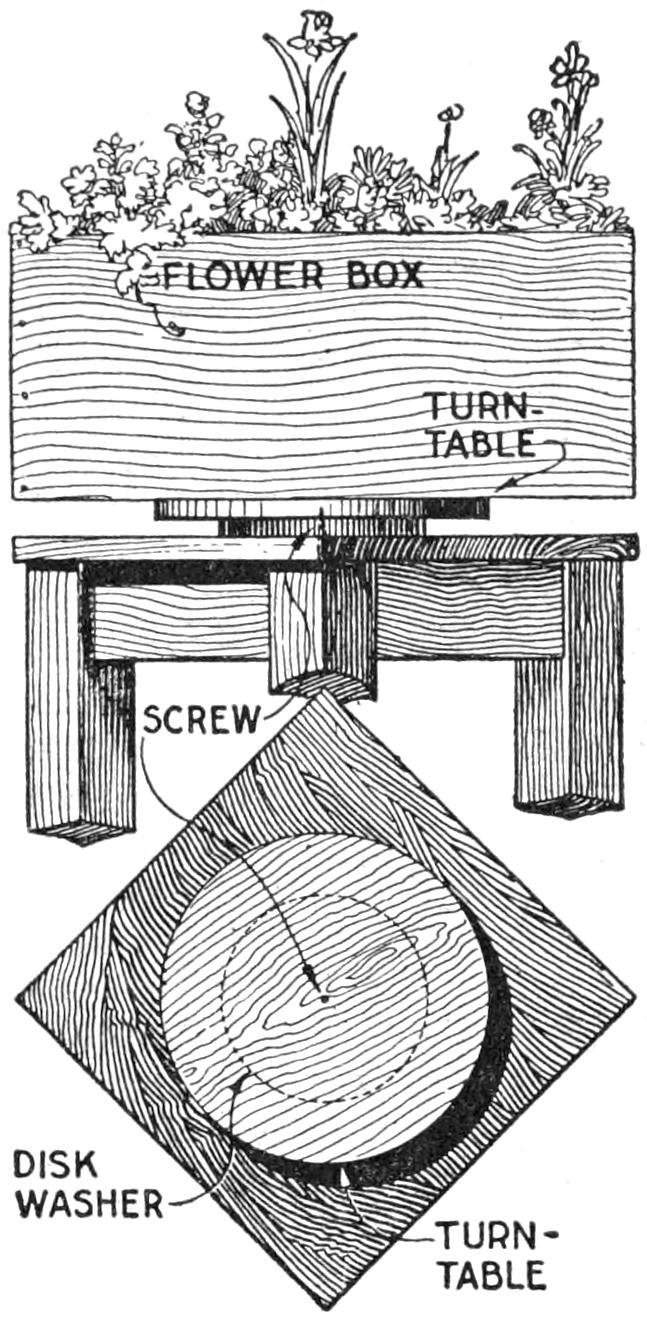
Potted flowers, if kept in the house, tend to grow toward the light. From time to time the pot should be turned. To do this more readily, the turntable stand shown in the sketch was designed. It is made up of a low, four-legged taboret upon which a 12-in. disk of 1-in. wood is fixed with a screw. A thin wooden washer, sandpapered and shellacked, insures easy turning. Rectangular boxes or circular jars look equally well upon the stand, the beauty of which depends much upon its workmanship and finish.—Edward R. Smith, Walla Walla, Wash.
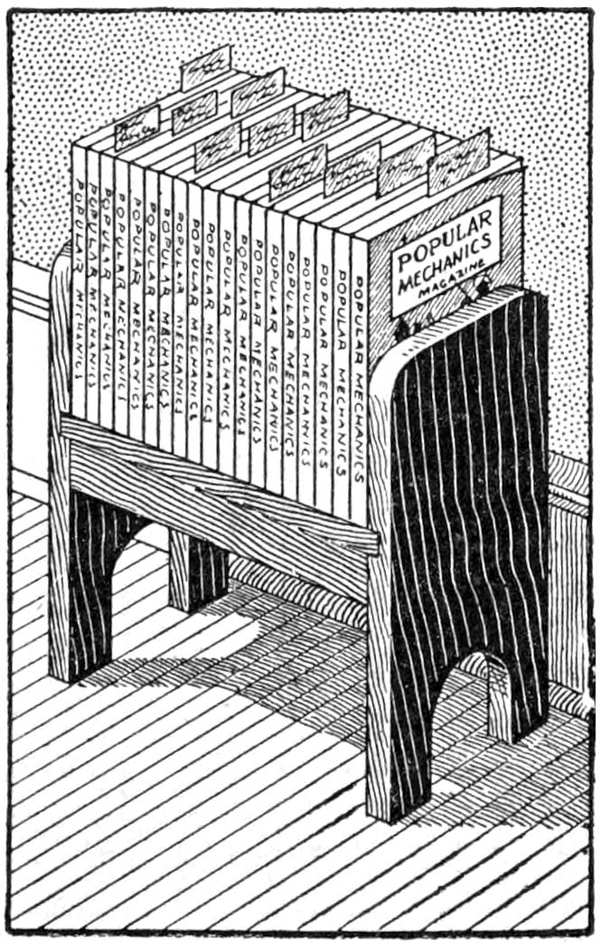
As it would be impossible to keep in one’s mind all the good ideas given in Popular Mechanics Magazine, I preserve my back numbers for reference, and, to reduce the amount of index and page searching, I have adopted a convenient plan of indexing any special article to which I expect to refer. I write, on one end of a strip of paper, the page and date of issue of the article. I place these slips at the proper pages in the magazine, so as to project at the top, as shown, making reference easy. If a slip drops out, it is quickly replaced. When articles are no longer needed for reference, the slips are removed. By keeping the magazines on an open shelf they can be reached handily, for reference as well as for removing them from the shelf.—J. E. McCormack, Haliburton, Ont., Can.
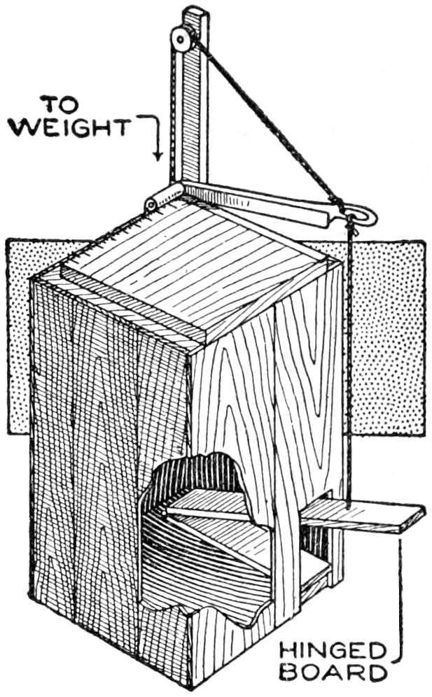
A trimming board with the knife operated by a pedal, leaving both hands free to handle the work, is a device appreciated by photographers, commercial artists, and others who have more or less heavy paper or cardboard to trim. An ordinary trimming board is mounted on a packing box of suitable dimensions, as shown. A pedal is hinged to the bottom of the box, and a heavy cord, or wire, runs to the handle of the knife, so that pressure on the pedal operates the knife. The latter is returned by a weighted rope, passing over a pulley attached to a standard at the rear corner.—H. F. Blanchard, New York, N. Y.
When it is necessary to serve a meal to a patient in bed, and no invalid table is at hand, use an ordinary folding card or serving table. Unfold one end over the bed, and a splendid substitute table is provided, useful for reading, games, and other purposes. If the table rests too low on the bed, adjust it with cushions. This is far more convenient than using a tray.—John P. Rupp, Norwalk, Ohio.
[309]
A comfortable and novel after-dinner chair for the man in the household can be made by fitting a morris chair, or other armchair, with devices which appeal especially to a man. The chair shown is that of the ordinary mission morris type. It is of simple outline and can be made by the home mechanic of fair skill in furniture making. The details of its construction, while not essential to a description of the special fittings, are shown in the several working drawings. The joints used for the framework are of the common mortise-and-tenon variety. The back is a plain frame, fitted with vertical slats, and hinged to a shoulder in the back legs, as shown in the side view. For a substantial piece of furniture, oak or other hard wood should be used; as a piece of porch or summer-cottage furniture, the chair may be made of softer woods. The cushion can be made of various leathers, or upholstery fabrics. It is built over a wooden frame and is removable. The seat bottom may be paneled, and a loose cushion fitted into it, and a similar one bound with thongs to the back of the chair.
The drawer is slightly different from the standard construction in that the front is arranged as a blind rail. It fits snugly between the front legs and is suspended from strips fitted between the pairs of legs at the sides.
No handle is provided, as the drawer can be opened easily by grasping it underneath the front board. Pipes, smoker’s supplies, or a variety of other articles may be stored handily in it.
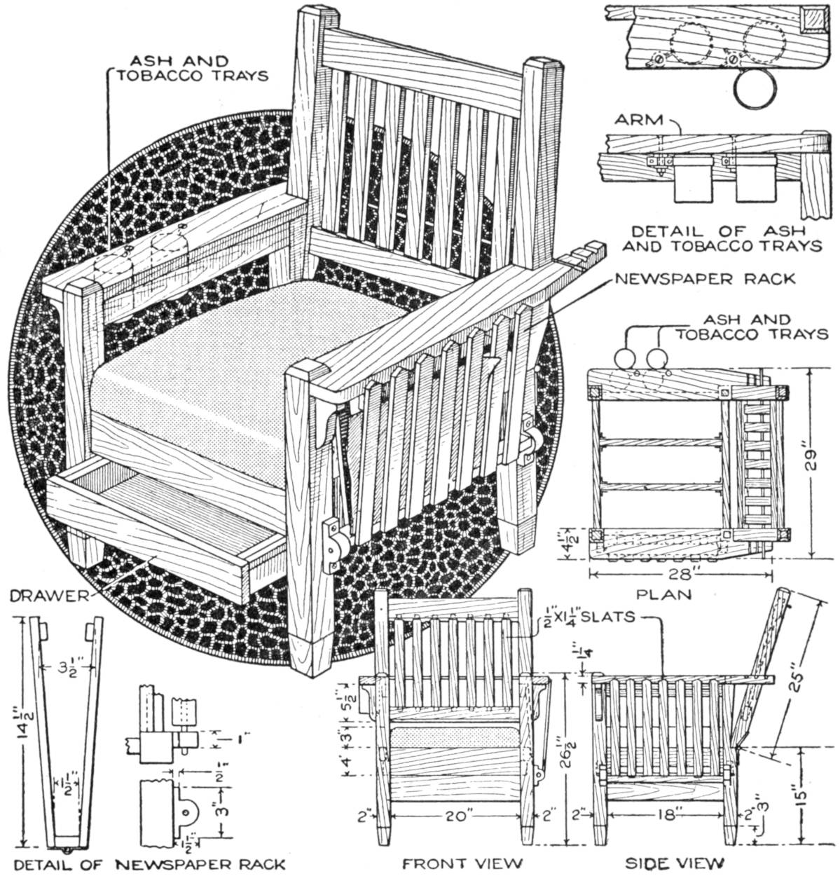
These Novel Features of a Morris or Armchair Increase Its Comfort and Usefulness, and can be Made Easily by the Home Mechanic
The newspaper rack, as detailed, is made up of strips forming a basket, which supported by a rod pivoted in wooden hangers, one on each of the side legs, adjoining the rack. When papers are not being taken out or placed in it, the rack is tilted back against the side of the chair arm. The ash and tobacco trays, which may be made large enough for cigars, are suspended under the right chair arm by means of rings made of strips of brass. These holders are pivoted on bolts, and the trays can be removed easily for cleaning. They are ordinarily swung out of the way, under the arm. The special features of the chair may also be adapted to the needs of nonsmokers.
¶The nuisance of soiled fingers and pen grip in lettering, when using a deep ink bottle, can be avoided by filling a bottle up to the neck with cement, and using only the neck as an inkwell.
[310]
An old six-foot folding screen, three-ply ¹⁄₄-in. panels from a packing box, and parts from secondhand talking machines, were used to make the cabinet shown in the photograph reproduced. The screen was cut down to form a framework of the desired height for the sides and back. Other parts of the screen were used for the frames of the doors on the front, and for the top. The panels were made from a good quality of three-ply stock, with a hardwood face, which was scraped, sandpapered, and brought to a very smooth finish. The material happened to have a pretty grain, and this added to the effect when it was stained and varnished. Pieces of this stock were used for the sounding horn and for other interior fittings, such as the shelves for records and the drawer below the horn. Space is provided for a large supply of records.
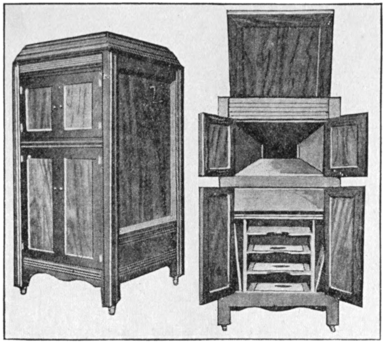
A Cabinet was Made by an Amateur Woodworker at a Cost of $16.35 for Materials
A secondhand two-spring motor, a turntable, and a sound arm from a disk machine were fitted into the cabinet, and gave excellent service. Care in staining the woodwork, shellacking, and varnishing it with several coats, gave the cabinet almost a commercial finish, and at a cost of $16.35 for all materials.
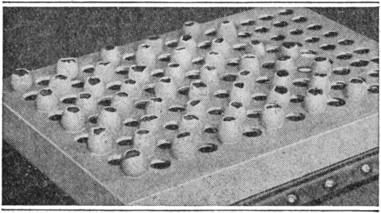
Seeds were planted in the Eggshells, Which were Broken without Disturbing the Roots When Transplanted
A novel method of caring for small plants until they are ready to be set out in the garden is shown in the photograph reproduced. Holes were bored in the bottom of the till of an old trunk and eggshells fitted into them. Seeds were planted in the shells and the names of the varieties were marked on them. The arrangement is compact, and when the plants are ready for planting, the shells may be broken, and the plants set without disturbing the roots—Charles Darlington, Des Moines, Ia.
In rifle practice it is often desirable to provide a target which will indicate to the marksman when the bull’s-eye is struck. The device shown in the sketch, arranged behind an ordinary card target, has given satisfactory results on a private range, and can easily be adapted for other uses.
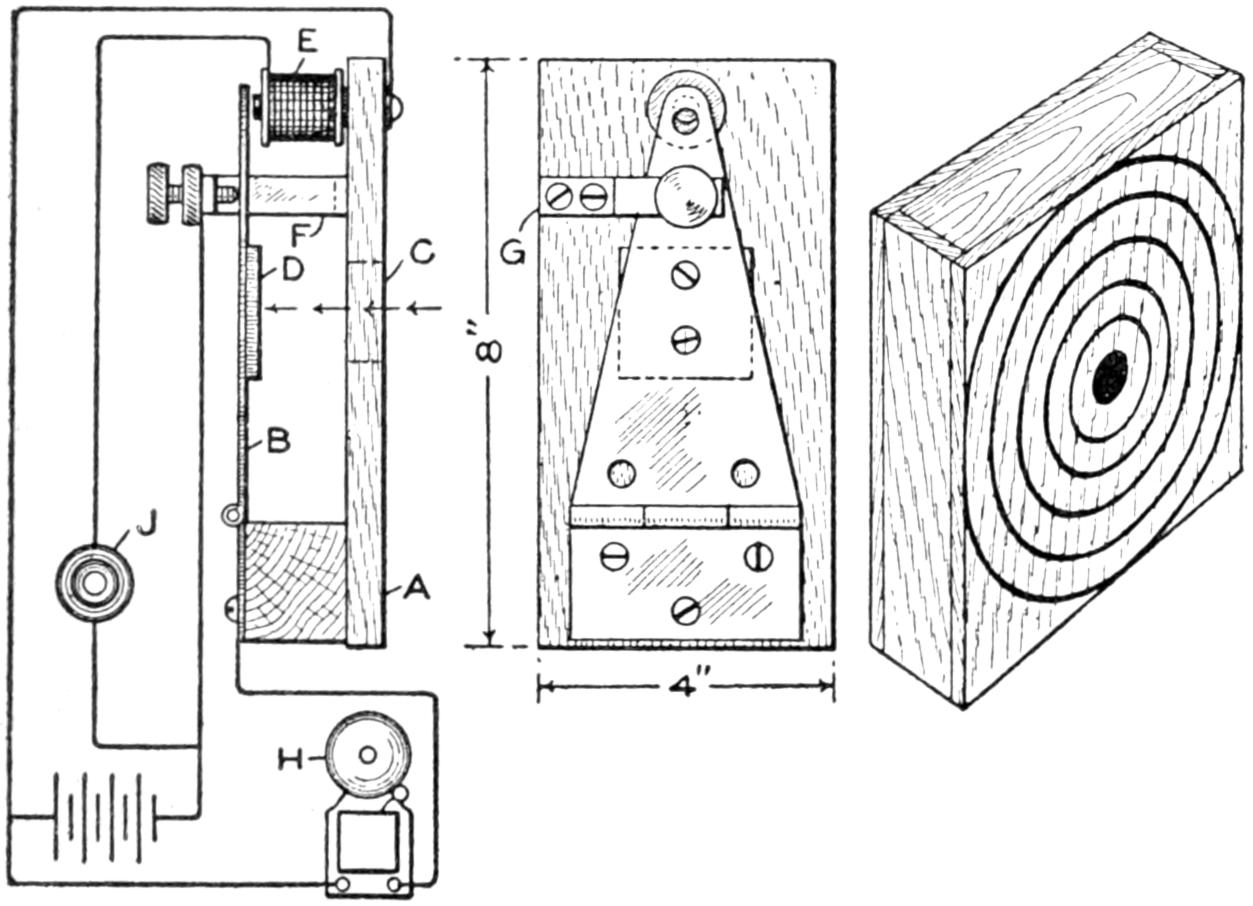
Fig. 1
Fig. 2
Fig. 3
The Bullet Forces the Hinge against the Thumbscrew, Causing the Bell to Ring
Referring to Fig. 1, A indicates a wooden base, 4 by 8 by ¹⁄₂ in., on which is mounted a strap hinge, B, 6¹⁄₂ in. long, by means of a block, 1³⁄₈ in. high. An opening, C, 1¹⁄₂ in. in diameter, is provided in the base, and a plate, D[311] 1³⁄₄ in. square, is riveted to the strap hinge opposite to the opening. An electromagnet, E, obtained from an electric bell, is mounted upon the base under the small end of the hinge. A standard, F, provided with a cross arm, G, is secured upon the base between the opening and the magnet. A thumbscrew with a locknut extends through the cross arm, engaging the rear side of the strap hinge, and permits an adjustment of distance between the core of the magnet and the surface of the hinge. A bell or buzzer, H, is connected as indicated, through the battery circuit. The electromagnet is connected through the battery and push button J.
The strap hinge normally rests against the electromagnet. The force of any projectile passing through the opening against the plate closes the bell circuit and indicates to the marksman that the bull’s-eye has been hit. By the closing of the magnet circuit, the strap hinge is drawn again into normal position and the bell circuit is broken. Figure 2 shows a front view of the circuit-closing device. The device may be mounted in any suitable box, as suggested in Fig. 3. The front of the box is covered with sheet metal, ¹⁄₁₆ in. thick, and the standard target card is mounted thereon.—John B. Brady, Washington, D. C.
¶A convenient method of holding paper in a roll is to fasten a wire clip at each end near the edge of the piece.
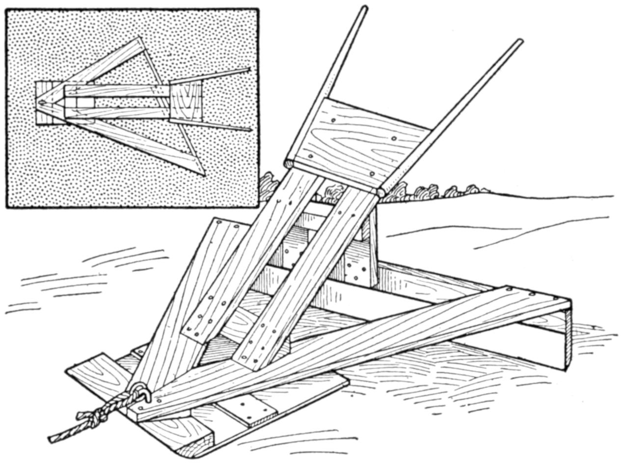
A Tennis Court was Smoothed and Leveled by the Use of This Scraper, Made Quickly of Rough Lumber
In order to level and scrape a tennis court, which was in bad condition, the two-man scraper shown in the sketch was made. It is built of rough lumber, and a metal shoe is fixed to the lower edge of the scraping blade at the rear. The bearing at the front is on a flat-bottom sled of wood, and the depth of the cut is regulated by pressure on the handle. The scraping blade is set at an angle, as shown in the smaller sketch. By lifting the handle slightly, the operator is able to deposit dirt in holes so that when the court is rolled they are filled evenly. Where a large number of courts are to be smoothed, the device may be adapted and made large enough to be drawn by a horse.—Edward R. Smith, Walla Walla, Wash.
I made springs for a small foot-power automobile by using barrel staves joined together in the shape of pointed oval wagon springs. Two strong staves were nailed together at each end and braced with a block where they were nailed. Two of these springs were placed over the rear axle and one of them was set over the front axle extending in the direction of its length. The wooden springs made the automobile ride comfortably.—Charles Delbridge, St. Louis, Mo.
[312]
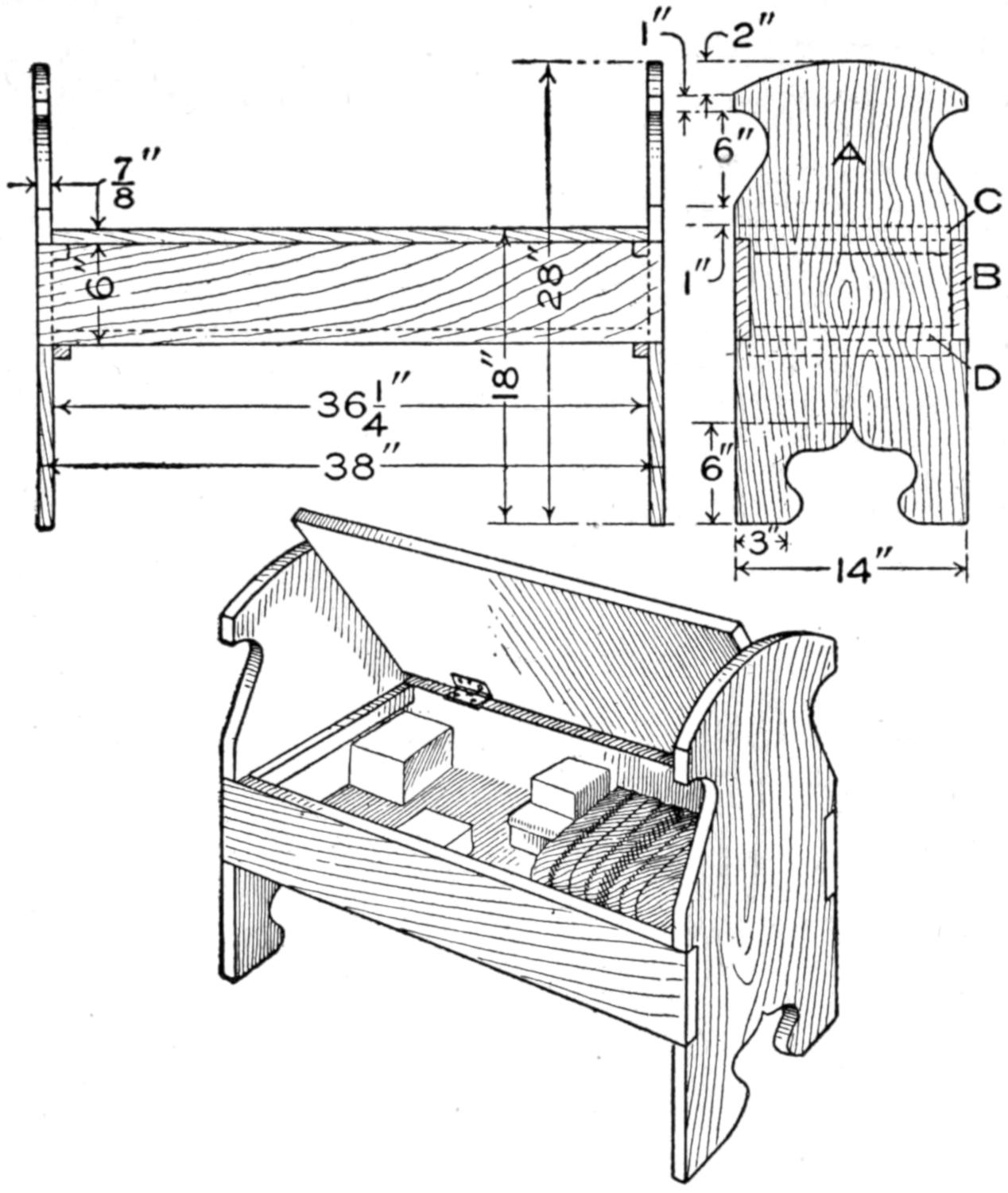
Details Showing the Construction of a Hall Seat to be Made in Mission Style
The illustration represents a simple design for an easily made and substantial hall seat, provided with a compartment for odds and ends. It is advisable to make it of wood to match its surroundings. The following material is necessary:
2 ends, ⁷⁄₈ by 14 by 28 in
2 rails, ⁷⁄₈ by 6 by 38 in.
1 seat board, ⁷⁄₈ by 14 by 36¹⁄₄ in.
1 bottom board, ⁷⁄₈ by 12¹⁄₄ by 36¹⁄₄ in.
2 seat cleats, ⁷⁄₈ by ⁷⁄₈ by 12¹⁄₄ in.
2 bottom cleats, ⁷⁄₈ by ⁷⁄₈ by 11¹⁄₂ in.
The two ends, A, are marked to the same outline and cut with a coping or scroll saw. If a fine-toothed saw is used, the edges of the boards can be easily smoothed with sandpaper, otherwise a file is necessary to remove the coarse saw traces. The rails B are cut to size and squared up at the ends, after which they can be placed at the proper places on the ends A, which may then be marked for the notches to receive the rails. In fastening the rails to the end pieces, 2-in. round-head screws can be used. The seat C is attached to the back rail by 2-in. butt hinges. To prevent the seat from sagging in the middle, it is supported on each side by cleats screwed to the end pieces A. If the seat is liable to warp it can be held straight by two cleats screwed underneath. The bottom board D may be held in place by means of screws through the rails, or by resting on cleats screwed to the end pieces. The seat, when assembled and thoroughly sandpapered, can be finished to suit.
To prevent a wire hook, when the last few turns are given, from marring or scratching the surface, special care must be taken. A splendid way to do the work neatly is to first lay a piece of stiff paper on the surface where the hook is to be attached and hold it in place while starting the screw hook. Turn the hook in the usual way through the paper. When the hook is in place the paper can be removed by tearing it off.—Contributed by Emile Parent.
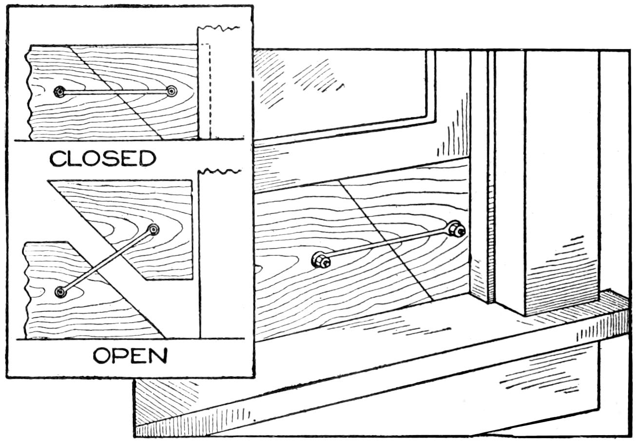
A Removable Window Board to Raise Lower Sash for Ventilation between the Sashes
The illustration shows a ventilator I constructed to allow air to pass through between the upper and lower window sash. It consists of a board 8 or 10 in. wide, and as long as the window sash is wide. A short distance from one end it is marked and cut on a slant. The small piece removed is hinged to the main part so that it can be raised in taking the board from the window. When the sash rests on the board it cannot be removed from the window.—Contributed by David Hannigan, Orange, Connecticut.
[313]

The floor space in our high-school shop is somewhat limited, leaving no room on the floor for the gluing press, and during a large part of the year the temperature on the floor is too low for gluing. We met these conditions with the gluing press illustrated.
Three pairs, or sets, of steps, A, were made of pine, 2 in. thick, and fastened in a series by strips B, so that they all would move forward or backward between the guides C, which are nailed to the floor above the shop. On one of the steps—the corresponding one in each pair—rests a piece of wood, D, 4 in. wide and 2 in. thick, through which, near its ends, are bored holes to receive lengths of 1-in. gas pipe, E. Over these holes and screwed to the wood piece are 1-in. floor flanges, F. The pipes E are threaded at one end so that they will screw through the floor flanges about 3 in. On the other ends of the gas pipes are fitted pieces of material, 4 in. wide and 2 in. thick, G, resting on washers, which in turn rest on the locknuts H. The locknuts H prevent the tees J from unscrewing in operating the press. A rod is used through the tees as a handle for screwing the pipes E on or out of the floor flanges F. On top of the pieces G rests the floor K, on which are placed the pieces to be glued. On the under side of the ceiling joists, and directly over the floor K, is spiked the 2-in. piece L, between which piece and the floor K the material is pressed. For the sake of stiffness and lightness the floor K is built up of 1-in. material, as shown in the detail. This floor may be raised or lowered by the windlass M. The windlass is simply a ³⁄₄-in. gas pipe turning in bearings fastened to the under side of the ceiling joists.
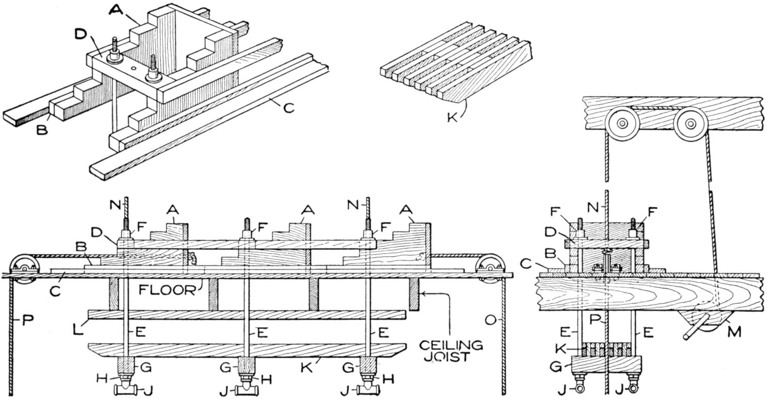
The Gluing Press is Attached to the Ceiling Where It Is Out of the Way and Where the Temperature Is More Correct for Making a Strong-Holding Joint
Supposing the press to be standing[314] as shown in the drawings, it is operated as follows: The pipes E are unscrewed so that their upper ends are flush with the top surface of the floor flanges F. The ropes N are wound up a trifle on the windlass M, thus raising the pieces D, the pipes E, and the floor K. Lifting D clear of the steps releases the latter so that the entire series may be moved to the right by pulling the rope O. In unwinding the ropes from the windlass, D is let down on the lowest step, which has just been drawn directly under it. This operation lowers the floor K to its lowest limit and the pieces to be glued are placed, one on the other, on this floor. If the total thickness of the material to be glued is sufficient to nearly fill the space between the floor and the piece L, a rod is thrust through J, and the pipes are screwed up, thus pressing the material between the floor K and the piece L. If, however, the material does not fill the space well, then the ropes N are wound up on the windlass M, thus raising the floor and its contents as far as possible, and by pulling the rope P the steps are drawn as far to the left as possible and D rests on a higher step, thus lessening the space to be taken up by the screws. The pipes are then screwed up tightly as in the first operation. Our press is operated from a mezzanine floor where all the gluing is done.
Make a plug of light wood, preferably cedar or white pine, 1³⁄₄ in. long and ³⁄₄ in. in diameter at the large end, tapering to ¹⁄₄ in. at the small end. Finish it to the shape of a minnow and bore a ⁵⁄₁₆-in. hole, 1 in. deep, in the large end. Make a lead plug, with a hole through the center, to drive tightly into the hole in the head of the minnow, and finish the front end smooth and even with the wood. Run a wire through the minnow and form an eye at the tail for hooks, and another at the head for the swivel. A three-cornered piece of tin inserted ¹⁄₂ in. back of the head on each side and bent so that the water will cause it to turn gives motion to the lure.
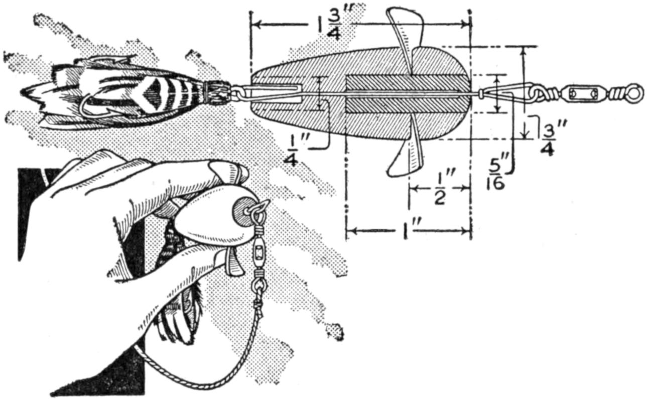
Bait Shaped Like a Minnow and Coated with Luminous Paint for Night Fishing
Two coats of luminous paint will be sufficient for the illumination. Expose the minnow to the light for several hours, and it will give a luminous glow in the dark that makes it easily seen by the fish as it is drawn through the water. As most game fish are night feeders, it makes a very effective lure.—Contributed by Charles Carrol, Saint Cloud, Fla.
When purchasing putty buy a little whiting. This is one of the ingredients of the putty. Mix enough of it with the putty to absorb the excess oil. This will prevent it from sticking to the hands. It also gives the putty more body and makes it much easier to handle.

The Small Lamp near the Switch in Circuit Glows When Lights Are On in the Basement
To avoid the loss of electric current by forgetting to turn out the light in the basement, I placed a 3-cp. lamp in the circuit near the switch at the head of the stairs. The small light is a signal that the light is still turned on in the basement.—Contributed by A. MacCunn, Toronto, Can.
[315]
An inexpensive, yet very efficient, die for cutting quantities of tin foil, sheet lead, paper, and cardboard can be made from a steel rule such as used by printers. Procure a rule, two points or about ¹⁄₃₂ in. thick, which comes in 2-ft. lengths. The rule can be readily bent without annealing. Bend it to the desired shape and solder, or weld, the ends together. To give it rigidity, fill in the space with melted lead to a depth of half the height of the die.
Place the material to be cut against the die and put both into a vise, or letter press. Apply pressure steadily until the die has cut through the last thickness of the material. As many as 5 pieces can be placed and cut at one time. When cutting designs for static machines, etc., from tin foil, this appliance does away with the tedious work of cutting one at a time, and then, too, they will all be uniform. In making the connection at the ends of the rule, be sure that they meet evenly and do not lap to make the joint.—Contributed by M. H. Granholt, Long Beach, Cal.
As a substitute for a vacuum bottle a very efficient pail can be made in the following manner: Procure a 1-gal. sirup pail for the outside and a ¹⁄₂-gal. size for the inside. Make a collar of tin, as shown, with projections; bend these down, inside and outside, then solder the collar to the inside of the larger pail, and the smaller pail to the inside of the collar. Be sure to make a perfectly air-tight joint in the soldering. This gives a double wall with an air-tight space all around the inner pail, or opening. To make vacuum covers for the pails, take two covers of each size and solder them together, as shown.
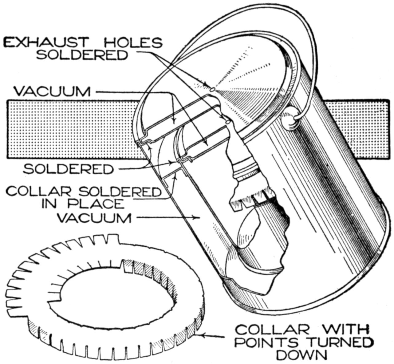
A Two-Wall Pail with Covers in Which a Partial Vacuum is Made
To produce a vacuum, make a small hole in the metal forming the collar, also one in each cover. Put a few drops of water in each vacuum compartment and set the parts on a heated surface. When the steam escapes, solder the holes. This will produce a partial vacuum in the space around the inner pail and in the covers. This will make a very efficient vacuum pail.—Contributed by John H. Spicer, Magnolia, Ark.
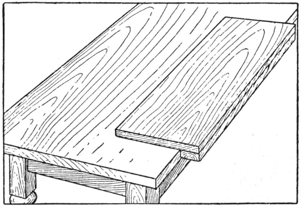
A Cleat Fastened to the Underside of an Ironing Board to Hold It on the Table Top
A handy ironing board for use on kitchen or dining-table top is made with a cleat to keep it from moving across the table top. The cleat, which is 1¹⁄₂ or 2 in. wide, is fastened to the board with screws. If desired, the board can be made as immovable as the table top by putting another cleat at one end, so that the two cleats will hold against one side and one edge of the table top.—Contributed by H. S. Craig, Rushford, Minn.
[316]
In planning a writing desk, much convenience can be added by providing it with a bookcase, in which may be stored those reference works most frequently used. The design illustrated furnishes ample room as a drawing desk, besides providing sufficient space in an inclosed cabinet for books or letter-filing cases.
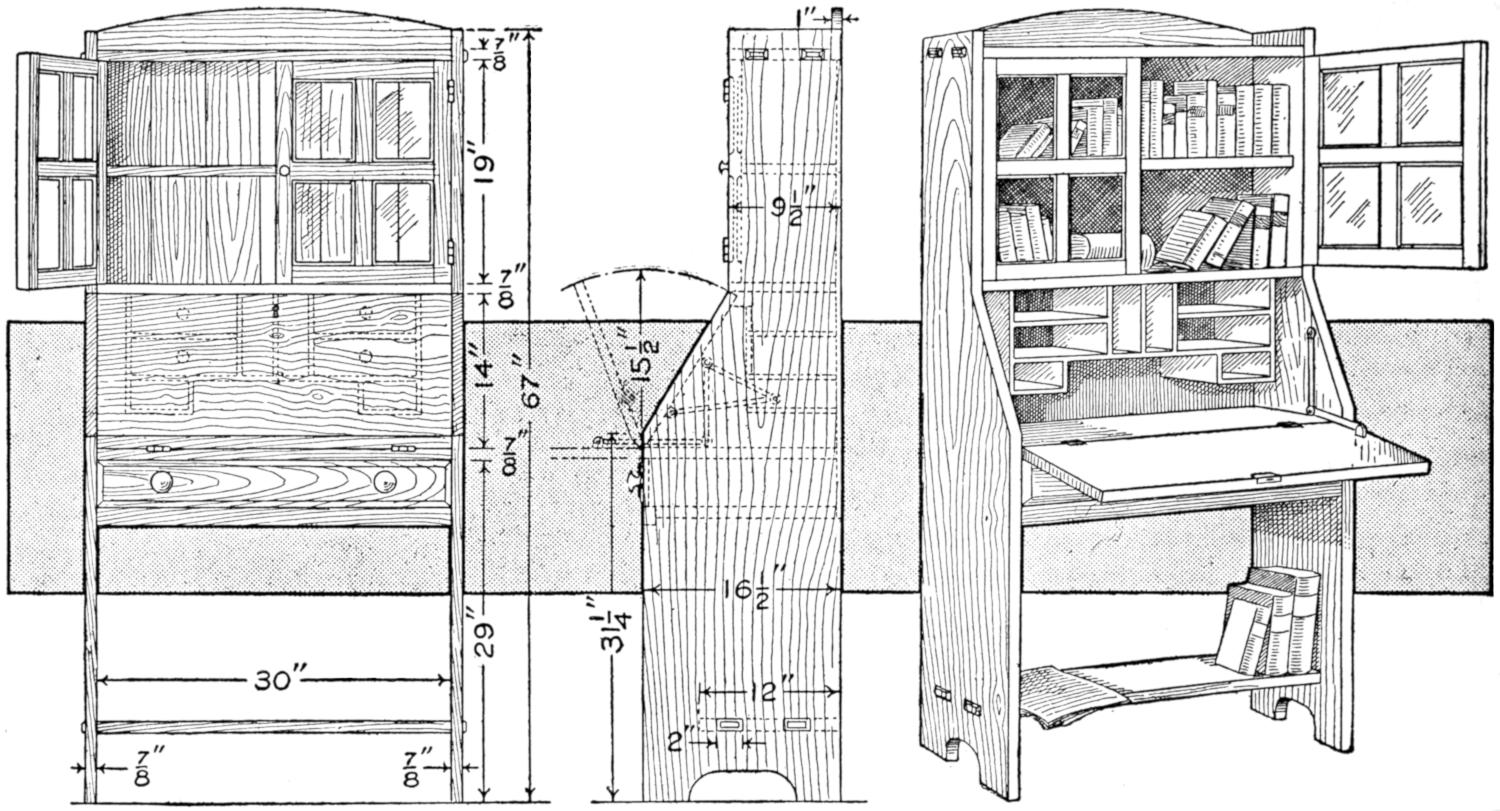
Combined Bookcase and Writing Desk Which can be Made Up in Golden Oak, Mission, or Mahoganized Birch, and will Appear Well with Other Furniture of Like Construction
The material required, figuring exact sizes, is as follows:
| 2 | sides, ⁷⁄₈ by 16¹⁄₂ by 67 in. |
| 1 | bottom shelf, ⁷⁄₈ by 12 by 32¹⁄₄ in. |
| 1 | top shelf, ⁷⁄₈ by 9¹⁄₄ by 32¹⁄₄ in. |
| 1 | back, ³⁄₈ by 40 by 31 in., made of pieces of convenient widths. |
| 1 | desk board, ⁷⁄₈ by 16¹⁄₈ by 30 in. |
| 1 | lower bookcase shelf, ⁷⁄₈ by 9¹⁄₈ by 30 in. |
| 1 | middle bookcase shelf, ⁷⁄₈ by 8³⁄₈ by 30 in. |
| 1 | desk cover, ⁷⁄₈ by 15¹⁄₂ by 30 in. |
| 1 | upper back rail, ⁷⁄₈ by 5 by 30 in. |
| Bookcase Doors | |
| 4 | stiles, ³⁄₄ by 1¹⁄₄ by 19 in. |
| 4 | rails, ³⁄₄ by 1¹⁄₄ by 13¹⁄₂ in. |
| 2 | mullions, ¹⁄₄ by 1 by 17¹⁄₂ in. |
| 2 | mullions, ¹⁄₄ by 1 by 13¹⁄₂ in. |
| 1 | pigeon-hole stock, ³⁄₈ by 7 by 72 in. |
| For Main Drawer | |
| 1 | front, ³⁄₄ by 4 by 30 in. |
| 2 | sides, ³⁄₈ by 4 by 15¹⁄₂ in. |
| 1 | back, ³⁄₈ by 3¹⁄₄ by 29¹⁄₂ in. |
| 1 | bottom, ³⁄₈ by 15¹⁄₄ by 29¹⁄₂ in. |
| 2 | drawer slides, ⁷⁄₈ by 1¹⁄₂ by 15 in. |
| 1 | lower rail, ⁷⁄₈ by 1¹⁄₂ by 30 in. |
| 1 | molding strip, ¹⁄₄ by ³⁄₈ by 120 in. |
As the main sides are of considerable width, it would be best to make them of two pieces glued together and, in order to obtain a strong and neat joint, to have this done by an experienced joiner, or in the mill. The back edges should be carefully planed, and rabbeted ³⁄₈ in. deep by ¹⁄₂ in. wide for the ³⁄₈-in. thick back. The bottom or foot piece of the sides should be squared up with the back edges, or the completed desk is liable to be winding, or warped. The bottom and top shelves or main cross braces should be marked and cut out, and, to be in harmony with the shape of the sides, the lower-shelf tenons are made wider than those on the upper shelf. The top shelf should be rabbeted ¹⁄₂ in. deep by ³⁄₈ in. wide, to fit the back boards which are nailed to it. The required mortises in the sidepieces are marked from the corresponding tenons of the shelves, and can then be cut out with a chisel. When finished, the four parts constituting the frame should be assembled, and may be held together with blind screws, or dowel pins, passed through the tenons.
The desk board and two library shelves should then be fitted, and fastened in place with blind screws through the sides, or with cleats from the inside. For a neat, finished appearance, the back boards should be carefully joined, exposing no cracks, and fastened with nails driven into the various[317] shelves. The upper rail, resting on the bookcase, and the lower rail, forming part of the drawer support, can then be fitted and secured to the sides with blind screws, either from the outside or diagonally through the rails from the inside. Drawer slides are fitted in place flush with the top edge of the lower rail, and fastened to the sides with screws.
In making the drawer, the usual construction should be followed. The front piece should be rabbeted near its lower edge to fit the drawer bottom, and notched ¹⁄₂ in. at each end to fit the sides. The bottom and end pieces fit into grooves cut in the sides. Suitable drawer pulls or knobs should be provided.
For the doors of the bookcase, the best construction would be to tenon the rails into the stiles about ¹⁄₂ in. The glass panel fits in a notch, ¹⁄₂ in. deep and ¹⁄₄ in. wide, cut around the inside ledge of the door, and is held in position with molding strips. In order to give the door an appearance of being divided into four parts, mullions, or cross strips, are fitted on the outer side of the glass flush with the rails and stiles, and fastened to them with brads. The doors are attached with butt hinges.
In making the desk door, a specially selected board should be used, as the finished appearance of the desk will greatly depend on this. The ends and sides should be perfectly squared, and the lower or hinge end cut beveled corresponding to the edge of the desk board. Butt hinges are used to secure it in position, and hinged brackets or chains provided to support it when open. When closed, it rests against a strip fastened to the lower side of the bottom bookcase shelf.
In arranging the pigeonholes it is best to have the inside boards rest on the desk board, so that, when desired, the entire arrangement of the drawers and shelves may be withdrawn easily. When thoroughly sandpapered and finished to taste, a serviceable, handy and attractive piece of furniture is obtained, suitable for either office or home.—Contributed by James Gaffney, Chicago.
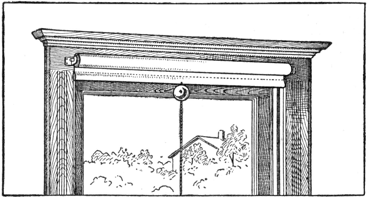
The Rubber Ball Fastened on the String at the Stick Prevents the Curtain from Winding Up
It frequently occurs, in adjusting spring-roller curtains, that the cord slips through the hand and the curtain not only winds up to the top but continues until the spring has spent its force, and the curtain and cord are rolled up out of reach. It is then necessary to use a chair, or stepladder, to readjust it. All this trouble and annoyance can be avoided if a small hollow rubber ball is obtained, and holes punched through so it may be threaded on the curtain string, and tied close to the stick. Should the curtain slip away with this attachment, the ball will jam up against the window frame, preventing further winding up.—Contributed by T. B. Lambert, Chicago, Ill.
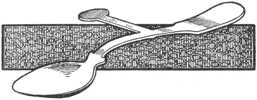
The Projection Keeps the Spoon from Entering the Mouth When Taken in the Left Hand
To discourage a child from using a spoon in the left hand, a projection was made of a piece of brass, filed into the shape shown in the illustration. After the projection was attached, the entire spoon was plated. This makes it impossible to use the spoon in the left hand, as the projection will prevent the bowl from entering the mouth.—Contributed by W. H. Hutchinson, Hamilton, Ont.
[318]
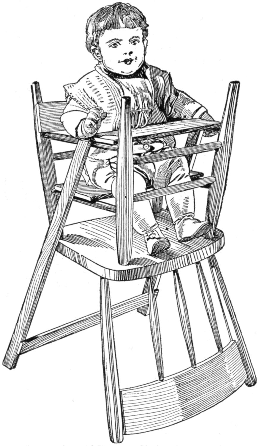
An Inverted Solid-Bottom Chair with Attachments Used for a Child’s High Chair
Where a high chair is not at hand or available, an ordinary solid-bottom kitchen chair can be used instead, if rigged up as shown in the illustration. The chair is reversed, and the back is used as one support, while two pieces of wood fastened to the sides form the other. A seat board is fastened to the upper side rounds, and a table board to the two lower side rounds. A small piece is nailed to the two back posts for a back.—Contributed by J. S. Fritzen, Minneapolis, Minn.
Having considerable trouble with a smoky fireplace when trying to start a coal fire in the basket grate, I decided to make a blower of sheet iron. A blower covers the upper part of the fireplace and forces the draft through the basket grate until the fire gets a good start, then it can be removed. Before making the blower I again had trouble one morning when the chimney would not draw, and the whole room became filled with smoke; I then grabbed a newspaper and held it up against the upper part of the fireplace like a regular blower. To my surprise the suction of the chimney held the newspaper in place without any outside aid. In a few minutes the fire was roaring, and best of all, when it became hot, the newspaper caught fire and was sucked into the flames. This in reality became an automatic blower, as it removed itself when no longer needed.—Contributed by Charles F. Kopp, Amite, La.
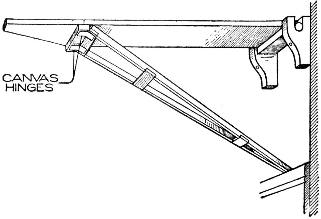
Ironing Board Supported on Wood Hinges at the Wall to Provide a Space for the Covering
One of the most useful and convenient articles for a household is an ironing board, one end of which is fastened to the wall by means of hinges to allow it to be folded up against the wall when not in use. Wood brackets are preferable to the metal hinges, as there must be some little space between the wall and the board to allow for the thickness of the covering. The brace which extends from near the end of the board to the base of the wall is best hinged with canvas strips, as they will last better than any other material for this joint. The hinges should be put in place when the board is in a vertical position to allow the brace to go in position without straining.—Contributed by J. H. Beebee, Rochester, N. Y.
[319]
When rowing a small boat, we were bothered by the turning of the oars in the locks, so that the blade of the oar was not in proper position to take the water. We overcame this by planing off slightly one side of the oar, so that when this surface was against the lock, the blade was in the correct position to catch the water. It is unnecessary to grip these oars tightly, as they fall naturally into place and save the novice a great deal of trouble. In locks where this method is undesirable, the handgrips may be cut as a guide.—H. D. Burnside, Madison, Wis.
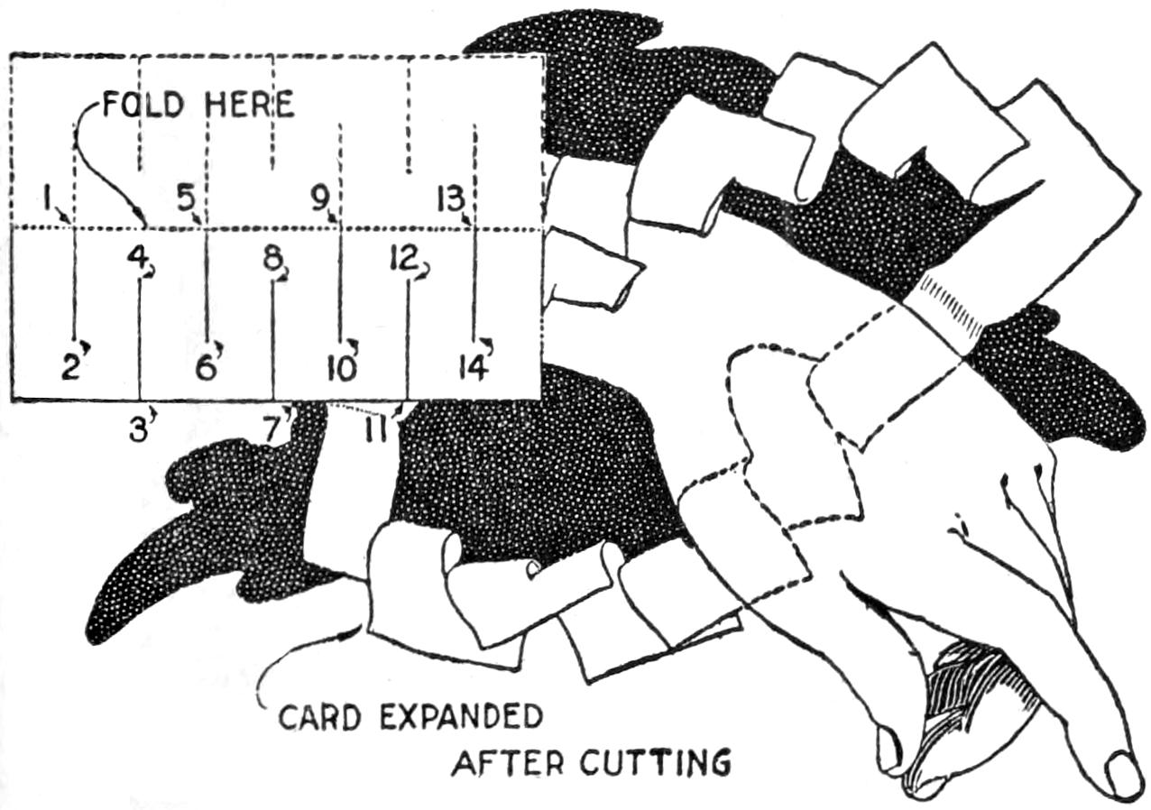
It Is Hard to Imitate a Quick and Skillful Performance of This Simple Trick
A trick that will amuse and interest persons both old and young can be performed with a calling card, cigarette paper, or other similar material, cut with a scissors or knife, as indicated in the diagram. The card is shown, and the performer announces that he will pass his hand through the card, making a bracelet of it. He will, of course, be challenged, and proceeds as follows: He folds the card lengthwise and cuts through two thicknesses from 1 to 2, 3 to 4, etc.; then opens the card, and cuts from 1 to 13. By stretching the paper, as shown in the sketch, the hand may be passed through the card readily. The spectators are soon trying to duplicate the trick.—R. E. Jones, Velasco, Texas.
Considerable pleasure and pastime was afforded by the tug-of-war game which I made. Two contestants, one at each end, take hold of the rollers with their forefingers and thumbs and endeavor to move the pointer to their respective ends. The game interests persons of various ages, and they all want to try it.
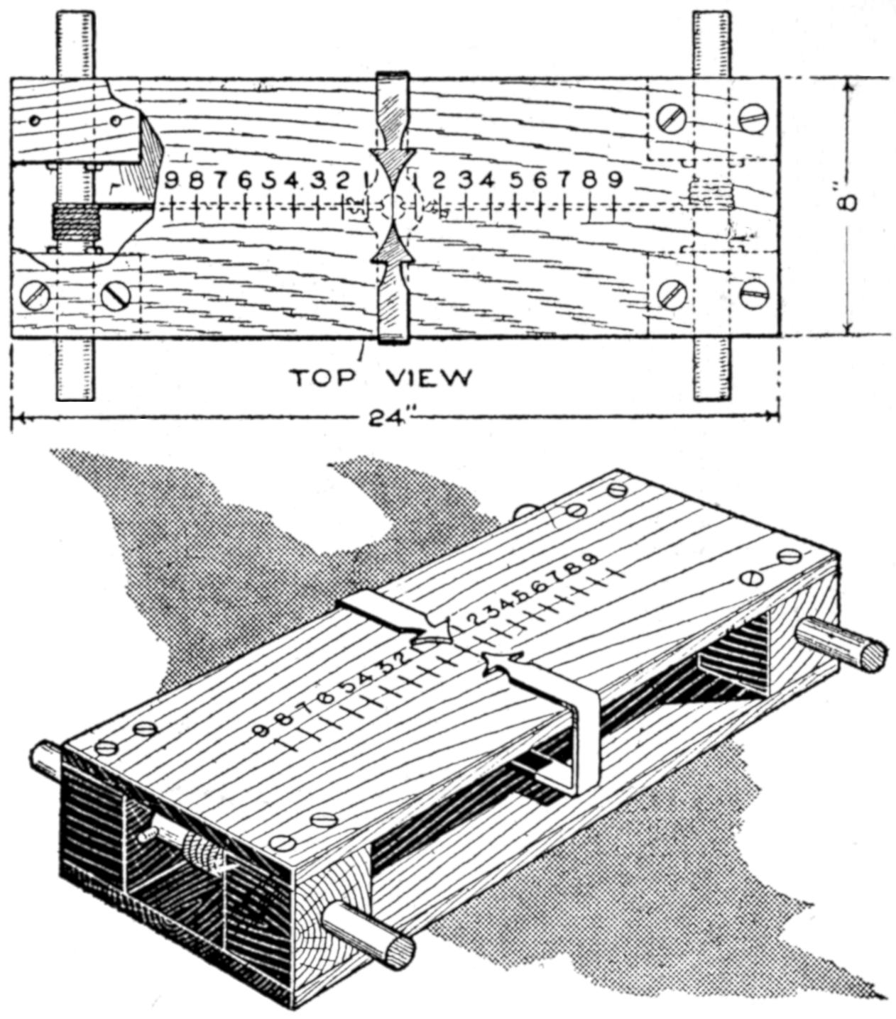
The Contestants Grasp the Rollers, One at Each End, and Attempt to Draw the Pointer Over in Their Favor
The device should be made strongly to stand the wear on it. The top and bottom are boards, ¹⁄₂ by 8 by 24 in., and four blocks, 3 in. high and 2¹⁄₂ in. square, are fastened between them at the corners with screws. The rollers are set in the blocks, and held by small nails passing through them and set against the inner faces of the blocks. The pointer is made of a strip of brass, bent to the shape shown. Cords extend from the pointer inside of the box and are tied to the rollers.—James E. Noble, Kingston, Ontario, Can.
¶In applying a white paint over a dark, or mottled, surface, tint the first coat with a little black, making it gray; then the next coat will show solid white.
[320]
The amateur photographer often has a poor dark room, sometimes made worse by the use of an evil-smelling lamp. If he wishes to use a room that has daylight, he finds it difficult to convert the room quickly for his purposes, especially if he desires to make use of the daylight for his work. Under these conditions, the arrangement described in this article was devised, and proved so satisfactory that I pass it on to the host of amateurs who find satisfaction in making part of their equipment. The table and window frame in place are shown in Fig. 1. The table is removed by withdrawing the rod, and bending up the hinged legs. The frame and window covering are removed by releasing the four small hooks. Ruby, yellow, or ground glass may be inserted in the sliding frame, as required, nearly all of the light being shut out, or light admitted without a glass, by sliding the frame.
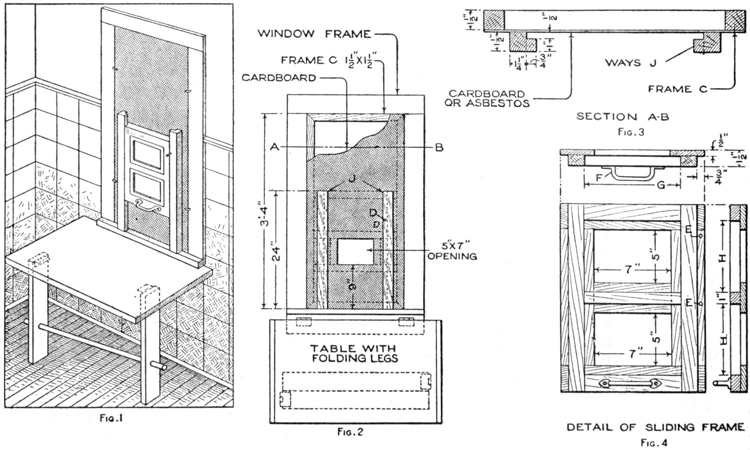
| Fig. 1 | Fig. 2 | Fig. 3 |
| Fig. 4 |
With This Sliding Frame and Folding Table, the Work of the Photographic Dark Room can be Done by Daylight in the Home Bathroom
The general arrangement of the parts is shown in Fig. 2. The dimensions are suggestive only, being suited to a small window in a bathroom, where the equipment was installed. The table is merely a board top supported by hinged legs, which are braced by a removable round wooden rod. A frame, C, as detailed in the section at A-B, Fig. 3, is fitted closely in the window casing. It is covered with heavy cardboard, tacked on. The ways J, in which the frame for the glass slides, are fixed to the lower rail of the frame C, and to a crossbar at its middle. A 5 by 7-in. opening is cut in the cardboard to admit the light, as shown in Fig. 2. Holes D are bored in the ways to receive pins which hold the frame at various positions, as indicated by the stop holes E, Fig. 4.
The sliding frame is detailed in Fig. 4. It consists of a back frame of ¹⁄₂-in. wood, sliding in the grooves of the ways J, and a frame of 1-in. stuff, mounted on the front of it. The openings may be made to suit the size of plate to be used, 5 by 7-in. openings being indicated. The openings are provided with rabbeted edges, as indicated by the width G, and the height H, in which frames of light weight, for the 5 by 7-in. glass plates, are[321] fitted. The frames may be made, or plain, cheap picture frames may be used. The sliding frame is raised and lowered by means of the handle F. The cardboard covering the larger frame should be painted a dull black, and the wooden parts may be shellacked in the natural color.
When developing films or plates, the frames with the red and yellow glasses should be inserted in the sliding frame, and held in place by turn buttons. The red glass will ordinarily be satisfactory for developing, but on very bright days, with the sun shining directly on the glass, a layer or two of “post-office” paper is placed over it. The yellow glass may be used when fixing, and other work requiring a subdued light, but not when developing is done. For printing, put in the yellow and the ground glasses, the latter admitting sufficient light for the purpose. To use the dark room occasionally in the evening, I set a lamp on a well-protected shelf outside of the opening in the cardboard, and proceed as in the use of daylight.
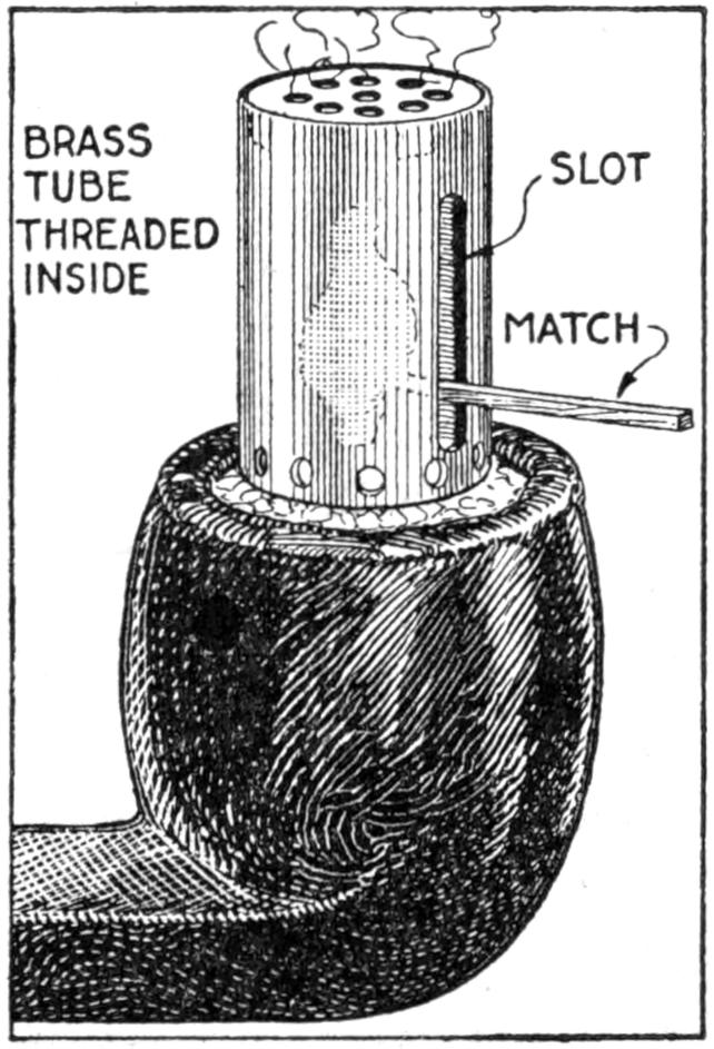
“It is a poor Irishman that cannot light his pipe when the wind is blowing,” but the sketch shows a device that will make a “Paddy” out of anyone, with a great saving of matches. It is made from a small piece of brass tubing, or drawn shell, ¹⁄₂ in. in diameter, and about 1¹⁄₂ in. long. The open end is placed in the bowl of the pipe or over the end of the cigar, a match inserted through the slot, and a quick stroke on the threaded portion ignites the match. The small holes provide air. The top is soldered in place.—James H. Rodgers, Montreal, Canada.
The intelligent housewife and shopper, as well as persons professionally interested in the structure and quality of woven fabrics of various kinds, can make good use of a counting glass for close examination of such material. In its simplest form the device consists of a cigar box with a ground-glass top and a small electric light inside. Where larger pieces of goods are to be examined a small table with wooden legs and wooden frame for the glass may be made.
Woven Fabrics are Examined under the Magnifying Glass and the Number of Threads to the Square Inch Counted
The diagrams at A and B represent the threads making up the cloth as stretched on the rollers of a loom. The lengthwise threads, or warp, are shown at A, and the cross threads, or weft, at B. By magnifying the material with a glass exposing an area of ¹⁄₂ or 1 in. square, the threads may be counted or closely examined and the quality determined. This also enables one to identify goods as being the same.—F. Ball Pinkus, La Crescenta, California.
¶An inexperienced workman broke eight curved window panes on a lake steamer by attempting to cut them on the inside, instead of on the outside of the curve, in fitting the glass.
[322]
An ordinary clock, fitted with an electrical device to record the length of telephone conversations or appointment hours, or indicate when a door is opened, is shown in the illustration. The record is made by the hands in contact with brass rings attached to the face of the clock, the front of the rings being covered with white paper, dipped in a chemical, on which black dots are caused to appear, at each contact. By examining the dots and noting the items corresponding to them on a memorandum, the length of conversations, etc., may be observed.
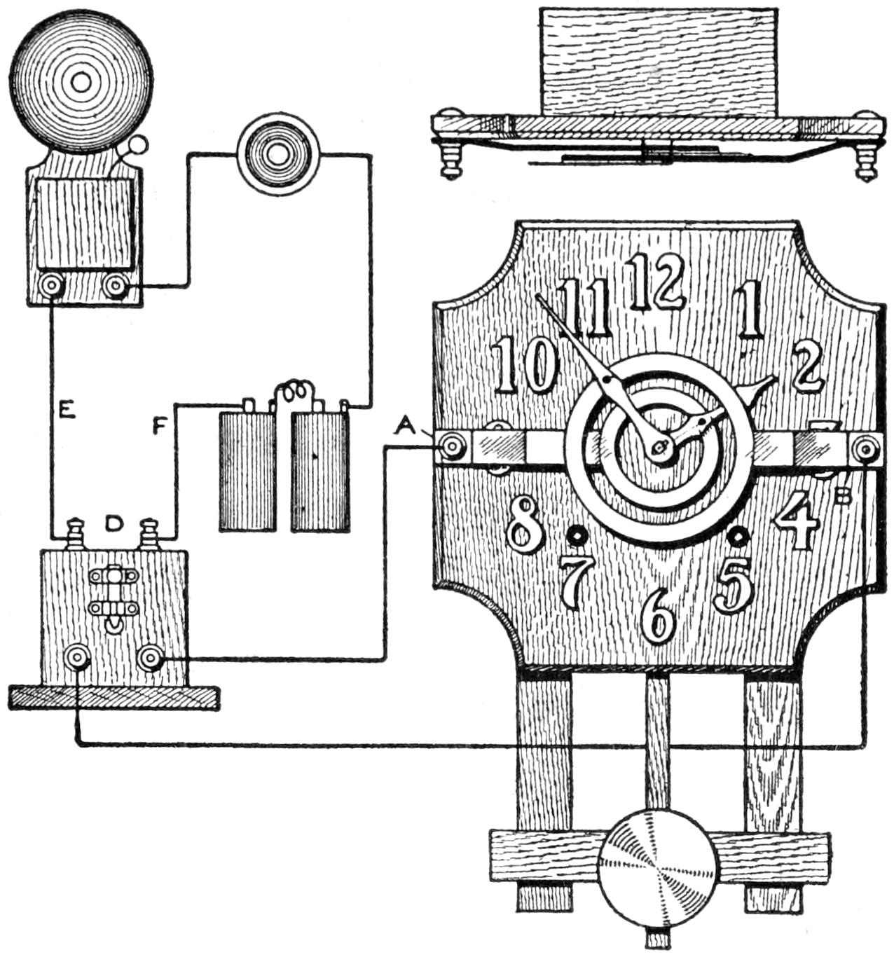
The Electrical Device Attached to the Clock Records Contacts Made by the Opening of a Door, and the Using of a Telephone
Two rings of ¹⁄₁₆-in. brass, one within the other, and having side arms, are mounted on the front of the clock, as shown in the illustration. The ring on arm A should be slipped under both hands, and should have spring enough to hold it in contact with the small clock hand. The ring fixed to arm B must be in contact with the large hand, but must be some distance from the small hand and the smaller ring, so that they will not come into contact when the hands cross each other. An offset in the arm A, and a piece of mica insulation, are provided where the larger ring crosses the bar A. On the surface of each ring, between it and its respective hand, is glued a piece of white paper, cut to conform with the ring, but ¹⁄₁₆ in. larger, so as to extend over the outer edge of the brass rings. The rings of paper are saturated in a solution of potassium chloride and permitted to dry, before being placed on the brass rings.
A high-tension current, passing through the coil D, enters the arm A, passes to the small hand, to the large hand, and out at the terminal on arm B. Black dots will appear on the prepared paper at the position of the hands, when the contact is made.
The primary wires E and F may be attached to a doorbell or to a contact on the door, indicating on the prepared paper the length of time the door was held open, as well as the time at which it was opened. The arms A and B must be well insulated from one another. For greater accuracy in recording time, to within ¹⁄₂ minute, prepared paper dials, with hour and minute marks, coming into contact with the hands at small projections punched in the hands from their upper surfaces, should be used. An ordinary secondary coil from an automobile may be used, and if the clock has a wooden case, the arms may be fastened directly to it.
Not infrequently home or shop mechanics find that trifling odd jobs are neglected repeatedly, simply because they are not of sufficient consequence to warrant getting out the tools or materials necessary for the work. A convenient method of insuring that these small jobs are not overlooked is to make a memorandum of them and place it with the tools required for the work. For instance, if a small job of soldering is to be done, a memorandum placed with the soldering outfit will not easily be overlooked, and the work may be done while the coppers are hot for use in a larger job. Likewise with small painting jobs. Sometimes only a brushful of paint is needed and one does not care to mix a small quantity[323] of paint nor clean the brush afterward. A memorandum of the job makes this unnecessary.—John Hoeck, Alameda, California.
Tire tubes may be vulcanized satisfactorily in the home garage, or even on the road, with the simple device shown in the sketch. It is made as follows: Obtain a piece of sheet iron, ¹⁄₄ in. thick, 3 in. wide, and 5 in. long. Drill a ¹⁄₄-in. hole at the middle of each end. Fit a strip of similar stock, 1 in. wide and 5 in. long, to the first piece with bolts, as shown. Procure a tin cover without embossing on the top, such as is used on baking-powder cans. Cut several disks to fit in the cover, from heavy cardboard; soak them thoroughly in a saturated solution of saltpeter, and dry them. Wrap each disk in oiled paper, and keep them in a water-tight container.
This Homemade Vulcanizer Utilizes the Heat from a Slowly Burning Disk of Cardboard
To use the vulcanizer, clean the area around the hole in the tube with sandpaper, and cut a piece of rubber of the proper size to fit over it. Slip one of the prepared cardboard disks into the tin cover, and clamp the cover and tire with patch into the iron frame, as shown. Touch a lighted match to the cardboard disk, which will burn rapidly, but without flame, supplying sufficient heat to vulcanize the tube.—Thomas W. Benson, Hastings on Hudson, N. Y.
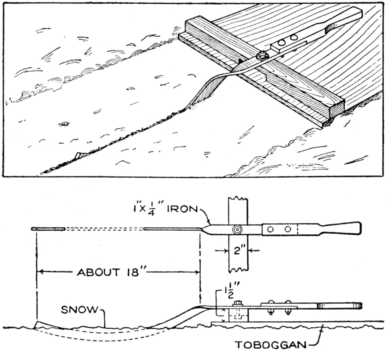
This Rudder for a Toboggan Insures Positive Control, and Prevents Wear on the Shoes and Clothes of the Rider
Learning to steer a toboggan by means of the foot dragged behind it is an interesting feature of the sport, but this method is dangerous at times and results in much wear on shoes and clothes. The device shown in the illustration makes this method of steering unnecessary and gives the rider accurate control over the sled. It consists of a strip of ¹⁄₄ by 1-in. iron curved to form a rudder at one end and twisted at the middle to provide a flat piece for pivoting it on the rear cleat of the sled, as shown in the working drawing below. A handle is fastened to the front end of the strip with bolts. The rudder should not be curved too deeply or it will cut through the snow and be damaged, or ruin the track.—H. B. Mclntyre, Waterville, Me.
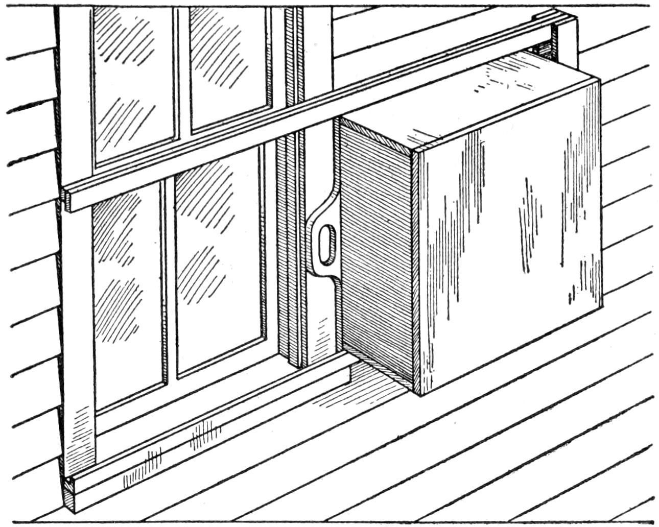
A Box Fitted on the Outside of the Window to Slide in Grooves Provides a Convenient and Inexpensive Refrigerator for Winter Use
A simple method of constructing a window refrigerator that will not obstruct the light is shown in the illustration. A box was made the width of the window and was fitted to slides fastened outside the window on the side of the house. The exposed sides of the box were inclosed completely and the inner side was provided with two sliding doors. A handle was fitted to the side of the box so that,[324] by reaching out of the window, the box could be drawn in front of the opening easily. Several shelves were fitted into it and the materials stored were not easily molested. Trunk casters attached to the bottom of the box improved the action on the lower rail.—Hubert Kann, Pittsburgh, Pa.
A paper glider is an interesting and useful toy that can be made quickly; it may be used out of doors, but occasions when weather conditions make it necessary to remain indoors are especially good for this form of pastime. The glider shown in the sketch was worked out after considerable testing. With a toss it travels 20 to 30 ft., on a level keel, with a message slipped behind a pin, as shown in the upper sketch. The inventive boy may devise many play uses for the glider in tournaments, competitions, and for “military” flights, in which the “drivers” of the devices may “annihilate armies.” Practical use of the toy was made in a series of air-current tests.
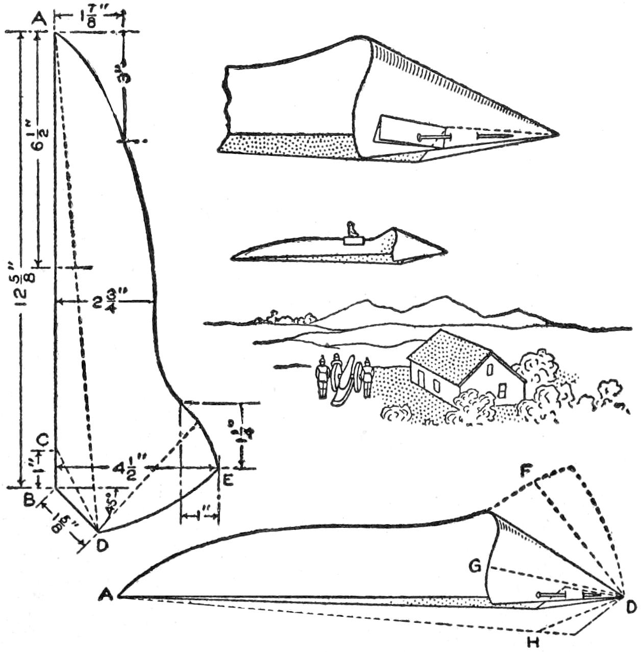
The Glider will Travel 30 Feet, Carrying a Message, if Carefully Made
The glider is made as follows: Fold a piece of paper, 10 by 15 in., lengthwise, and mark the outline shown at the left upon it. The dimensions should be followed carefully. Measure first from the end A to the point B, and then draw the slanting line to D, at an angle of 45°. Mark the width to E, and measure the other distances from A and at the middle, to determine the curve of the edge. Mark the dotted lines extending from D, which are guides for the folding of the paper to form the glider, as shown in the lower sketch. Curl the points under the side so that the line FD comes to the position DG, and pin them to the corners H, as shown in the lower sketch. The glider is tossed by holding it between the thumb and forefinger at the middle of the fold underneath it.—S. R. Edwards, Seattle, Wash.
A simple way of cleaning a clock is as follows: Remove the pendulum and procure a ball of cotton wool, about half the size of a fist. Saturate this with kerosene, and place it in a saucer, or a tin lid, in the case under the works of the clock. Close the case and leave the cotton for several days. It will then be found that the fumes from the kerosene have brought down the dust from the works; in fact, the cotton will be covered with black specks. It only remains to oil the bearings of the works, and the clock will be quite in order.—S. Leonard Bastin, Bournemouth, England.
[325]
One of the chief difficulties in developing plates in a nonreversible developing tank is that irregular development takes place, because the developer tends to settle more or less, depending on the time necessary for complete development. The construction of a reversible tank is a simple matter, and the cost is slight. The tank described is 3¹⁄₄ by 4¹⁄₄, in. in size, but the dimensions can be varied for other sizes of plates. The tank is a box having grooves in opposite ends for the plates. By placing the latter back to back, 12 can be developed at a time. Sheet rubber is fitted between the cover and the body of the tank, and the cover, upon being screwed down, makes a water-tight compartment of the box. The asphaltum paint used is not affected by the developer, and preserves the wood. Fixing and developing may both be done in the one tank, but it is preferable to use the tank for developing only.
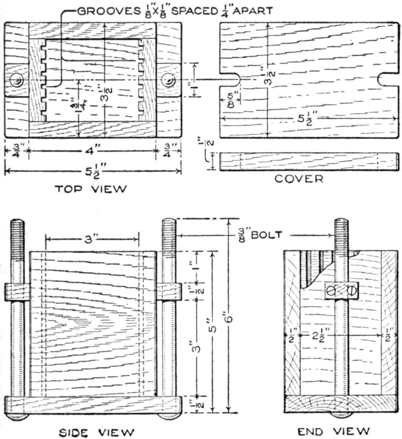
Assembly Views, Showing the General Construction and Detail of the Cover
The two sides are plain pieces, ¹⁄₂ by 4 by 4¹⁄₂ in. in size. The end pieces have ¹⁄₈ by ¹⁄₈-in. grooves, ¹⁄₄ in. apart and extending the length of the piece, which is ¹⁄₂ by 2¹⁄₂ by 4¹⁄₂ in. long. The grooves can be made either on a power saw, or by chiseling them out by hand. The bottom piece is ¹⁄₂ by 3¹⁄₂ by 5¹⁄₂ in. in size, with two ³⁄₈-in. holes bored to receive the bolts. The two bolt supports are ¹⁄₂ by ³⁄₄ by 1 in., and are also bored ³⁄₈ in. to receive the bolts, and are nailed to the end pieces. The cover is ¹⁄₂ by 3¹⁄₂ by 5¹⁄₂ in. long, with a slot in each end for the bolts, which are ³⁄₈ by 6-in. carriage bolts.
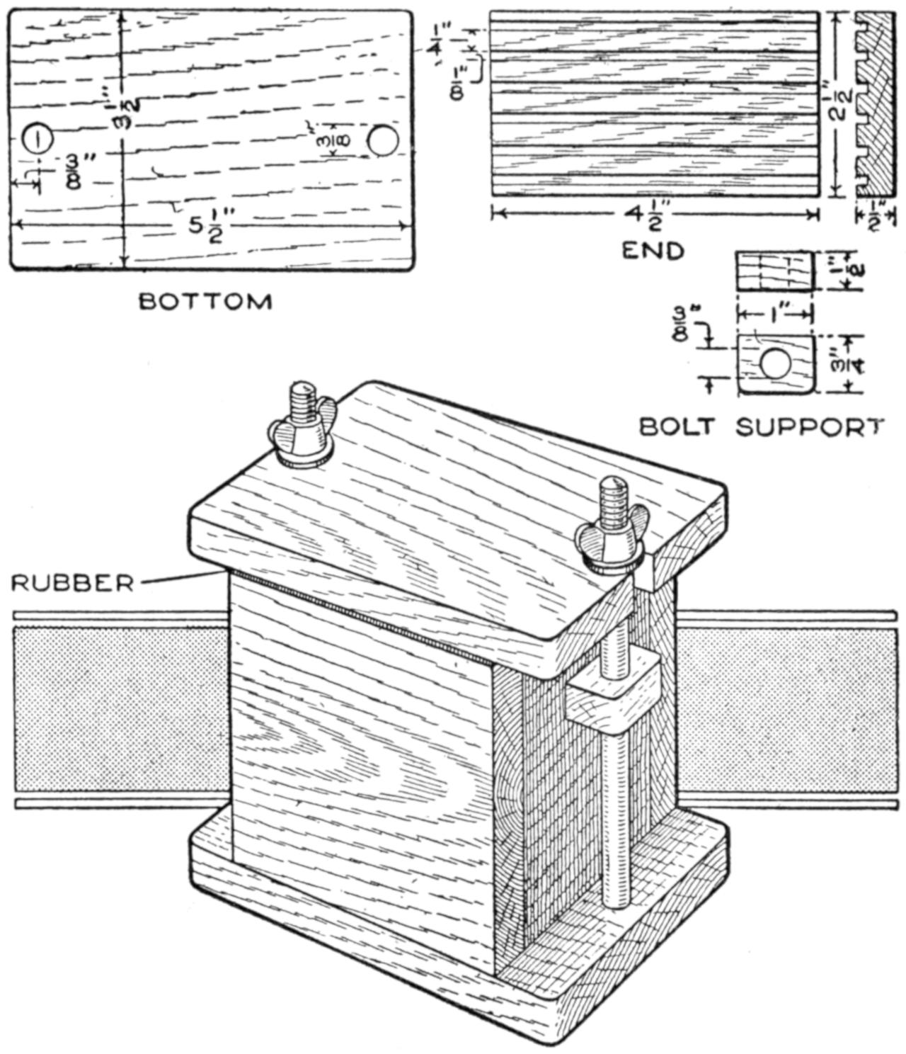
The Finished Tank, and Details of the Bottom, Ends, and Bolt Supports
The parts are assembled with screws, and the tank is given two coats of asphaltum paint. Care should be taken, before assembling the parts, to insure that the plates fit the grooves.
The making of a cane is a favorite job for the home craftsman, especially the veteran who finds himself in need of such a support and has the leisure to make it. A novelty in constructions of this kind is a turned cane built up of[326] dark and light-colored woods with snakes inlaid. That shown in the illustration was made of black walnut and birch, with a walnut knob. It is made as follows: Glue up a piece of walnut and a piece of birch, ⁷⁄₈ by 1³⁄₄ by 3 ft. long, as shown at A. Mark out the snake on the birch surface, and cut it out very carefully on the band saw, or with a fine hand turning saw. The snake portion will drop out and is then separated into a walnut and a birch strip, making two similar snakes. Bore holes for the eyes and plug them with the opposite kind of wood. Replace the snakes in opposite positions, the one of birch in the walnut side, and the walnut one in the birch side. Glue them carefully into place, removing a small portion of the wood at the ends of the sawed pieces to make a close fit.
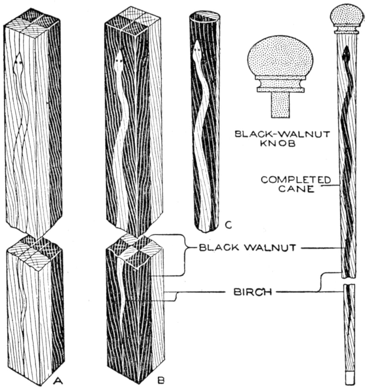
This Novel Cane can be Turned in a Lathe or Planed from the Square Stock, and Arouses Curiosity as to its Construction
The stock then appears as at B, and is ready for turning in the lathe. If desired, circles may be laid out on the ends of the stock, and the piece planed down to the rounded and tapered form of a cane. This is a more tedious job, but if carefully done with sharp tools will give good results.
Turn down the shaft to the desired thickness, as shown at C, the upper end being about 1 in. and the lower end ¹⁄₂ in. in diameter. Turn a knob of walnut as suggested, and after sandpapering the work carefully, finish it with shellac. Tip the bottom of the cane with a suitable ferrule.—E. K. Wehry, Cedar Rapids, Ia.
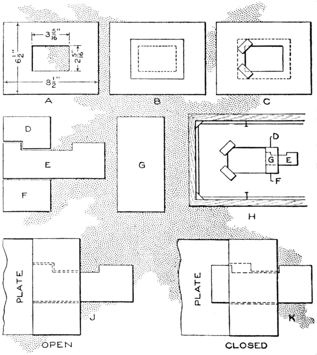
This Dry-Plate Kit is Made of Cardboard and Serves the Purpose Admirably if Carefully Fitted
Wishing to use some 2¹⁄₄ by 3¹⁄₄-in. plates in a 6¹⁄₂ by 8¹⁄₂-in. camera, I made kits that proved satisfactory, as follows, the method being adaptable also to other sizes: A piece of cardboard the size of the camera plate was procured. A rectangle, as at A, was cut in the center, ¹⁄₁₆ in. larger each way than the plate. Paste, over the back of the cut-out rectangle, a sheet of tough, thin paper, B, and glue two small pieces of cardboard, as at C. Cut cardboard pieces D, E, F, and G, proportioned as at H, and glue them into position, G being over the others, the piece E sliding. If a dry plate is placed in the rectangle and E is slid toward the plate, it will hold the latter in position. The plate holder is loaded with the kit, and to prevent warping, a couple of pins are driven into the plate holder, as at H. Figures J and K indicate the open and closed positions. The ground glass is marked to correspond with the rectangle, so that one can tell where to focus the image.—L. L. Llewellyn, Piedmont, Calif.
[327]
Many amateur photographers have occasion to make a considerable number of prints and find the washing of them tedious, by the ordinary methods. In order to overcome this difficulty the print-washing machine shown in the sketch was made. It is simple in construction and performs the work quite satisfactorily at a saving of not a little time. Since the water in which the prints are washed must be agitated, a pivoted tray is provided. A unique feature is the water wheel through which the water supply passes, at the same time developing power to operate the rocker arm, by means of which the tray is agitated.
The frame for the large trough, which contains the tray and other apparatus, is made of 2 by 4-in. uprights, braced with 2 by 2-in. pieces. The trough is made of ⁷⁄₈-in. stock, joined at the ends with a water-tight grooved, or dado, joint. The top is fitted to form a cover and may be hinged or arranged as a lid, supported and held in place by cleats, fixed on its under side with screws. The trough and its fittings may be made of a size suited to individual requirements. The device illustrated is 4 ft. long, and has a trough 18 in. wide and 13 in. high. The interior of the trough is given a coat of tar to make it waterproof, and the exterior may be painted thoroughly to preserve the wood.
The rocking tray, in which the prints are placed, is made of ⁵⁄₈-in. stock. It is 5 in. high, 15 in. wide, and 28 in. long. Splash boards are fixed at its ends, as shown, and the bottom is made of muslin, reinforced with wooden strips, ¹⁄₂ in. wide. The tray is supported on a rod or pipe at its center, the ends of the support being set into the sides of the trough. A crank arm of wood or metal is attached to the center of one end of the tray, and operates through an opening in the top of the trough. The crank arm engages a crank fixed to the shaft of the water wheel, as shown in the sketch. The crank must be made not longer than 2 in., or the resulting action on the tray will pour out too much water, the prints being thus in danger of damage.
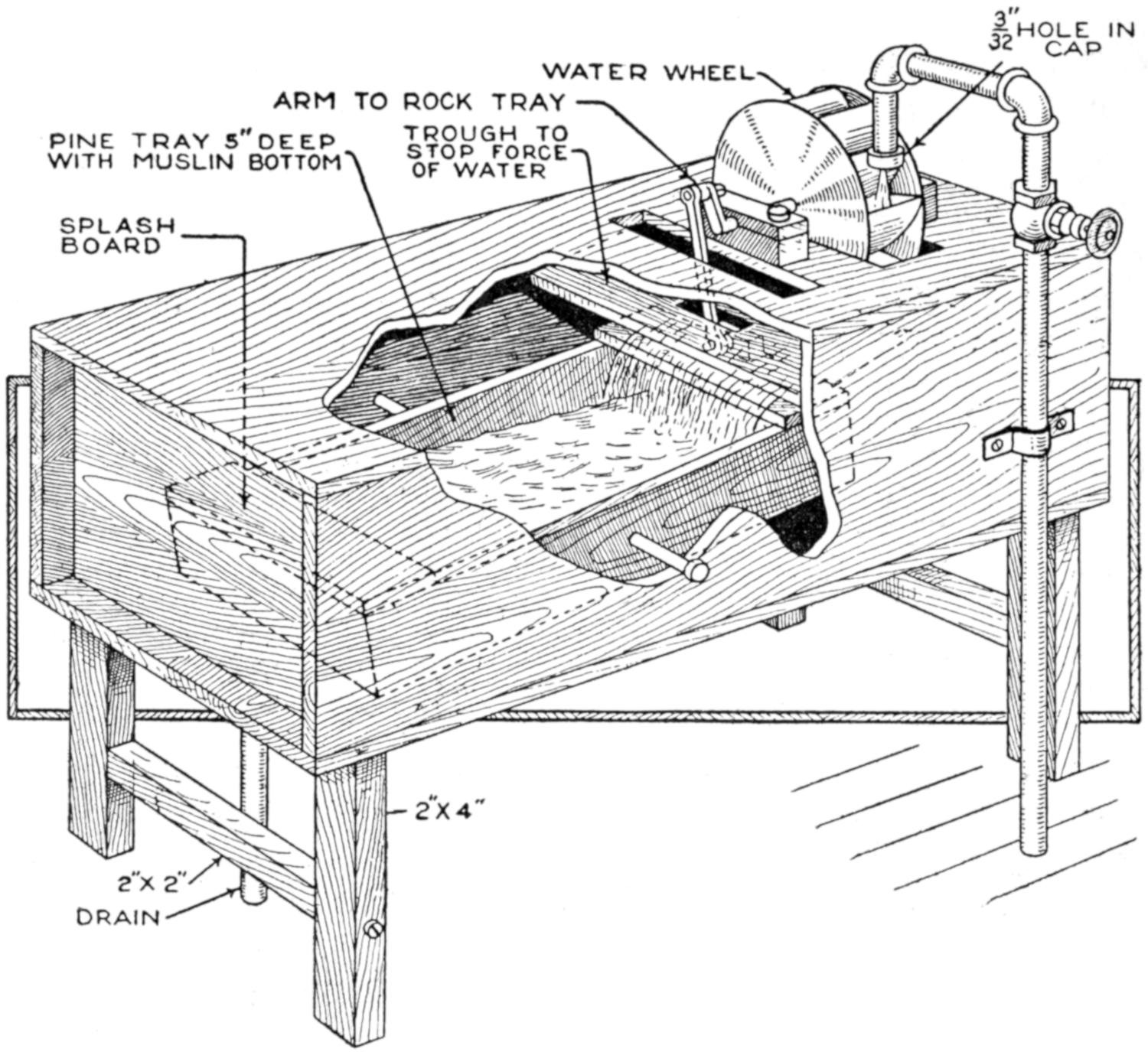
The Spray Forced from the Pipe Gives Power to the Water Wheel, Which in Turn is Transferred to the Rocker Arm Attached to the Tray
The water wheel is made of two round disks of sheet metal, 9 in. in diameter. Strips of wood are fitted between them so that the wheel is 3 in. wide on the face. Wooden blocks, grooved to fit the shaft of the water wheel, are used as bearings. They are fixed to the top with bolts. The water supply is provided through a pipe at one end. A cap is fitted over the end of the extension on the pipe and a small hole drilled through it. This forces the water against the blades of the water wheel rather than permitting it to drop under normal pressure. The flow of water is regulated by the valve on the[328] supply pipe, and the excess water is drained off at the opposite end of the trough. The force of the water, as it leaves the water wheel, is lessened, and the water carried gently to the tray, by means of a board set between the top and the tray, at the wheel end of the trough.
To make this washstand, I mounted a cheese box on a frame 20 in. from the floor, and fitted a shelf between the legs 9 in. from the floor. In the center of this shelf a hole was cut, with a compass saw, to hold a wash basin. Rods between the legs are handy for towels, washcloths, etc. Within the circular box are kept baby’s toilet and bath articles. The inside of the box is padded with cotton and lined with nainsook, the latter being used, also, for the cover. When the cover is on the box, the stand is used as a small table. White enamel gives the stand a neat finish.—F. E. Brimmer, Dalton, New York.
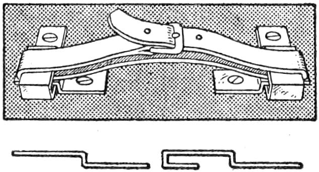
The illustration shows how to make a locking device for hand cases or satchels, and providing, also, a strap for carrying. Cut two pieces of ⁵⁄₈ by 2-in. strap iron, and two pieces, 2¹⁄₂ in. long. Bend them, and fasten them with screws or rivets, as shown. When the case is carried, the strap holds the crosspieces firmly.
A hole was bored about an inch from the center of a disk talking-machine record and the latter was placed on the machine with the new hole over the center pin of the table. When the record was played, the result was a reproduction extremely amusing and hardly recognizable as compared with the original one.
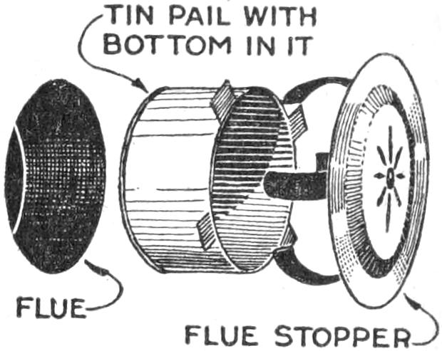
The usual method of covering stovepipe holes in chimneys with a tin disk is not as safe as it should be, especially adjoining nonfireproof material. A safer method is to fit a tin can, or a tin pail, into the chimney hole, as shown. Cut it off the right length, with a pair of tin shears, leaving projections as stops, and replace the disk stopper.—J. A. Raught, Janesville, Wisconsin.
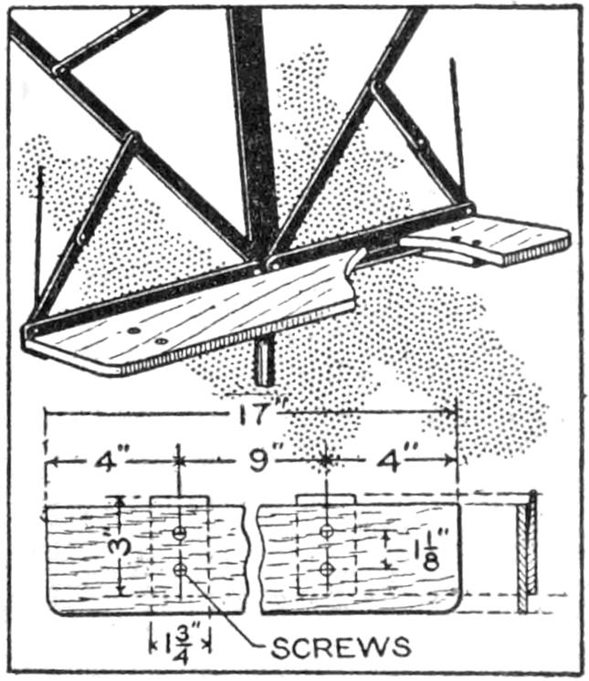
The music-stand attachment shown in the illustration aids in the handling of music books, and is easily made. Some stands are provided with a supporting edge about 1 in. wide and will not properly carry larger music books, and the device is attached to this edge. The device is of wood, ³⁄₁₆ by 3¹⁄₄ in., and the length of the stand. On the bottom, two wood strips are fastened. They are beveled as shown in the sectional view, to wedge on the music rest.—L. R. W. Allison, Newark, N. J.
[329]
Among the uses made of discarded steel talking-machine needles are the following: as glazier’s tacks; as brads, where a headless nail or an inconspicuous one is desired; as pins for fastening papers together; and for the tacking in of the backs on picture frames.—William A. Martin. Jersey City, N. J.
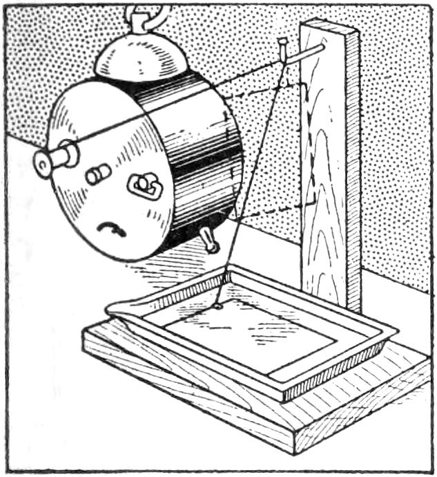
A photographers’ automatic print-washing device may readily be made with the aid of an alarm clock, and a spool to which a piece of thread is attached as shown. The spool is fixed to the alarm-clock winder. An upright support, having a nail driven into the top and bent over to form a hook, carries the thread, to which the print is attached by a small clip. The alarm-clock mechanism is then set, and when released draws the print from the dish, the bell warning the operator.—George H. Holden, Chesterfield, England.
Sectional poultry fencing has several advantages over stationary fencing: It can be easily moved, the poultry yard being made larger, smaller, or shifted; an area may be planted to a crop and gradually included in the yard, furnishing greens for the poultry. Also, the tenant who does not care to put down permanent equipment, will find sectional fencing desirable.
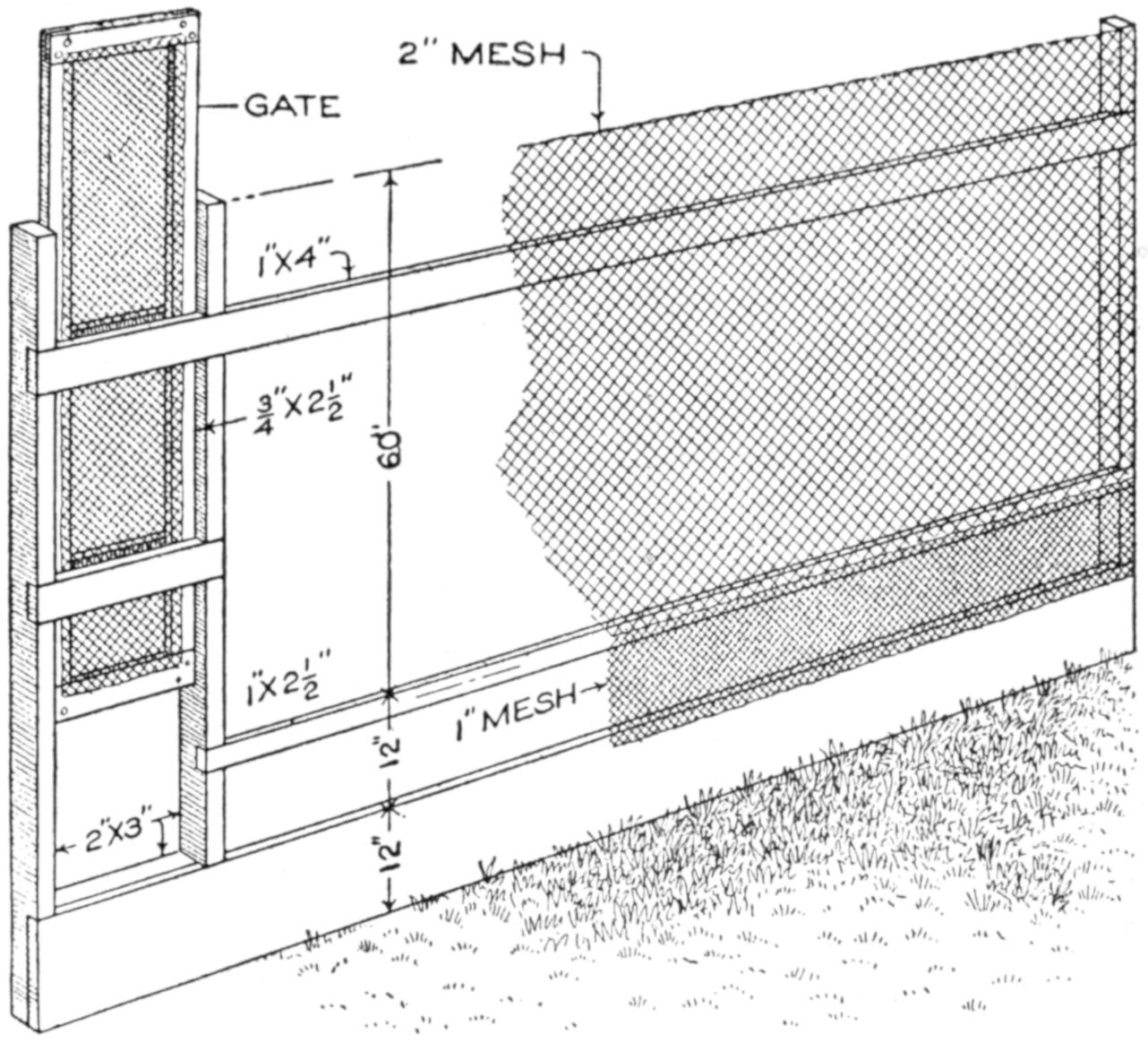
Poultry Fencing Made in Portable Sections Has Several Advantages over a Stationary Barrier
Sections are practical to about 18 ft. long, and should be 7 ft. high for the lighter breeds of poultry. If the fencing is to be used for grown stock only, the fine-mesh wire below may be omitted, and 2-in. mesh used. Some sections should be fitted with gates, and the top batten should be set down about 1 ft., so as not to afford footing for the poultry. The sections are lashed together with wire, and supported by an occasional post, or guyed to buildings or supports.
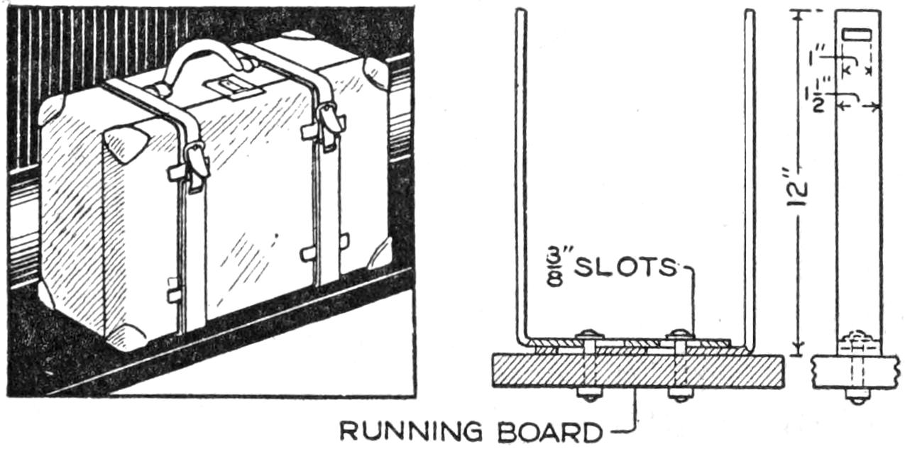
These Homemade Supports Are Adjustable to Suitcases of Varying Widths
Two metal strips, ³⁄₁₆ by 1¹⁄₂ by 20 in., were used to make a strong and adjustable holder for suitcases carried on the running board of an automobile. One-inch slots were cut near the top of the strips, which were bent to form angles having an upright portion 12 in. long. The angles are adjusted at the bolts, as shown, and the suitcase is held in place by straps.—Lucien G. Baer, Los Angeles, Calif.
[330]
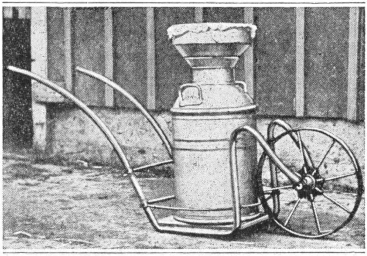
Milk Cans were Handled Easily by Means of This Homemade Cart
Large cans for milk are awkward to handle and transport in the dairy or barn, and the cart shown in the sketch was made from an old wheelbarrow and sections of pipe, to make this work easy. The pipes were bent to the shape shown and strongly braced with iron rods. A board bottom was provided, and the barrow wheel was mounted between the forked ends of the frame. The cart may be used for numerous other purposes, and is especially convenient in that the load need only be lifted slightly.—Monroe Woolley, San Francisco, Calif.
By placing two ordinary plain butt hinges so that two of their wings overlap completely, they may be made to serve as a double-swing hinge. If the holes do not correspond in the adjoining wings, drill new ones, disposing them to give the best hold in the wood. Allowance must be made in applying the hinge, for the double thickness of the center portion.
¶A rubber finger tip is convenient in counting sheets in that the paper is not soiled, since moistening of the finger is unnecessary.
Photographers who wish to construct a part of their equipment may be interested in a portable skylight, which I made and use with thorough satisfaction, for home portraiture. Covered with imitation leather, it is quite presentable in carrying it about. Figure 9 shows the case closed, with stand, flash lamp, box of flash powder, and a white-cloth reflector inside. The apparatus set up for work is shown in Fig. 5, and the details of construction in the other sketches.
First make the frames for the top and bottom of the case, A, of ³⁄₈ by 2¹⁄₂-in. wood, and B, of ³⁄₈ by 1¹⁄₄-in. stock, lengths and construction as shown in Fig. 3. Cut from extra-heavy mount board, two 21 by 28-in. pieces, C, and tack one to one side of each of the frames. Cut a similar piece, E, 15 by 26¹⁄₂ in., and hinge it with strong cloth, or thin leather, to the inner side of the thicker frame, to form the roof E, Fig. 5. Hinge the two frames with three butt hinges.
The frame is then ready for covering, and for this purpose imitation leather is economical and practical. Two yards of 36-in. material is needed. Use hot glue, first on the bottom half of the case, applying it smoothly, and press the fabric into place. Then cover the sides, the upper half, and the roof. The covering must be in one piece to prevent the smoke from escaping at the joints. Glue down the edges inside of the case, and set it aside for 24 hours to dry.
While waiting for the case to dry, the work on the bag can be done. Two yards of close-woven white muslin, or one yard of 60-in. sheeting, is required for the front. For the sides, closely woven black material should be used. Figures 1 and 2 show the dimensions, the white portions representing patterns, and the shaded portions material[331] for hems and seams. The material is folded over the pattern, basted down, and hemmed at the dotted lines, 1¹⁄₂ in. from the edge. Sew the front to the curved sides. Allowance for shrinkage, when the bag is washed and fireproofed, has been made in these sizes.
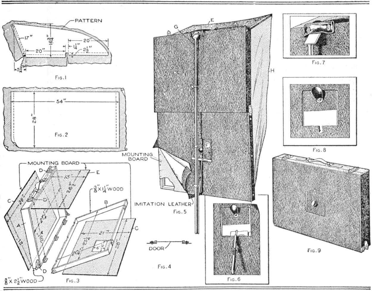
| Fig. 1 | Fig. 5 | Fig. 7 | |
| Fig. 2 | Fig. 8 | ||
| Fig. 3 | Fig. 9 | ||
| Fig. 6 | |||
| Fig. 4 | |||
This Homemade Skylight was Made at a Cost of $3, Gives Satisfactory Service, and Is Not Unsightly
For fireproofing the bag, the following formula is good: water, 60 oz., ammonium phosphate, 4 oz., ammonium chloride, 8 oz. Soak the fabric half an hour, wring it out slightly, and hang it up to dry.
Cut a hole, 6 in. square, in the lower half of the case for the door F, Fig. 5. The door is of galvanized sheet iron, 7 in. square, covered on one side with imitation leather and provided with a leather handle. The door slides in guides of mount board, or metal, as shown in Fig. 4. Figure 8 shows the notch below the door to allow play for the spring of the flash lamp, in place in Figs. 5 and 6. Mine was made for cartridges, but by attaching a pan of heavy tin, I use it for flash powder.
The leather socket, into which the top of the holder G, is slipped, is shown in detail in Fig. 7. Suitcase catches, D, lock the apparatus in open or closed position. The roof E, is supported by two folding desk slides.
To fasten the bag in place, slip a cheap yardstick, or strip, cut to the proper length, in each of the hems at the edges, and set them snugly inside and against the sides of the open case and under the edge of the roof. Fasten them with screws, as shown at the edges in Fig. 5. The bag is easily removed by withdrawing the screws and the strips, for washing and fireproofing it again. The front must hang away from the lamp before the charge is fired, or the bag may be burned. After firing the flash, the skylight is carried out and the smoke expelled.
[332]
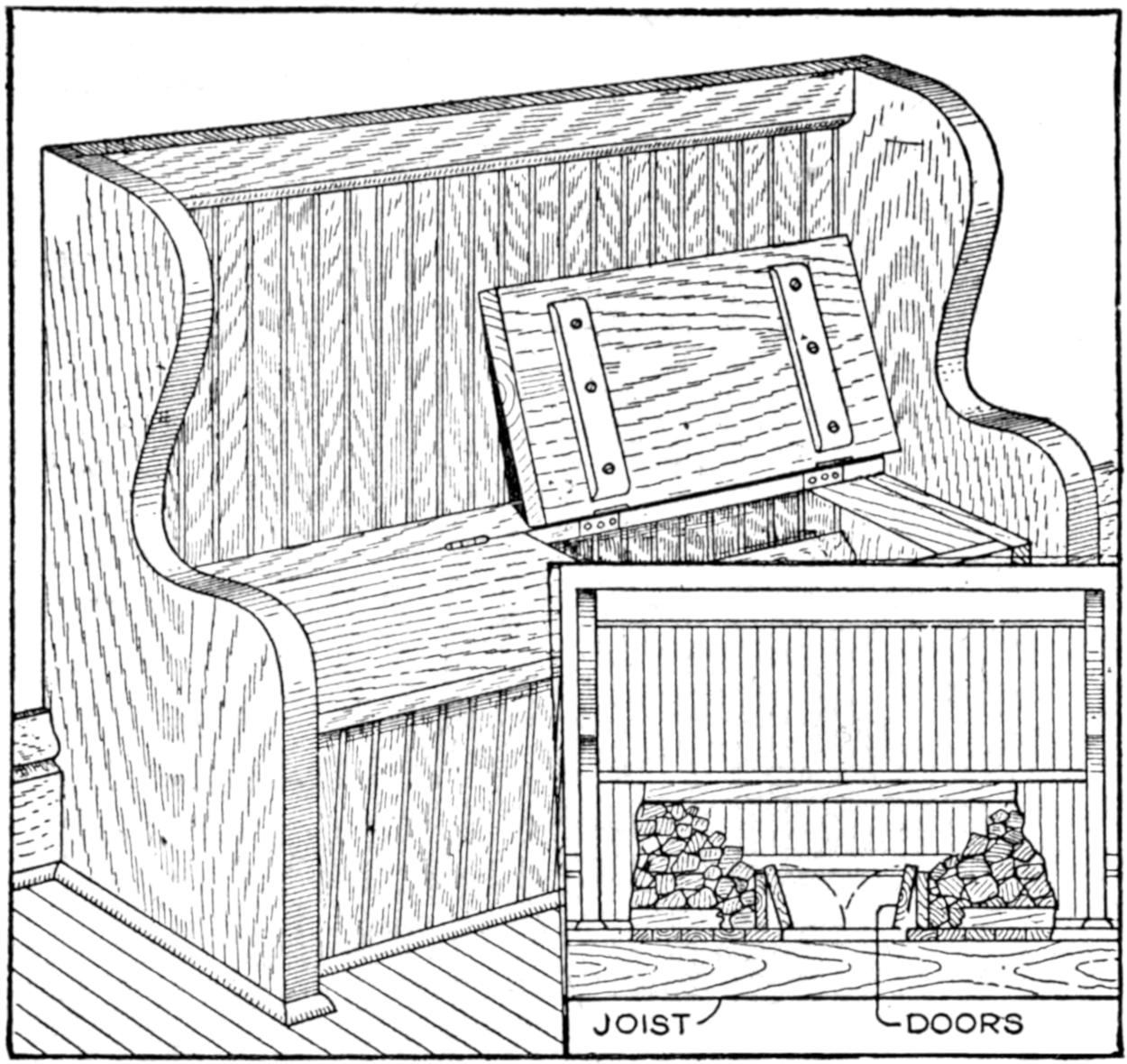
The Fuel is Placed in the Box by Passing It Up through the Trapdoors in the Floor
A fuel box for the fireplace may be easily arranged so that it is unnecessary to carry the fuel through the living rooms, thus avoiding soiling floors and rugs. It may be installed, as shown, for a summer cottage, or even in the living room of a home. The fuel box is built under the seat of a comfortable settle, and the wood, coal, etc., are placed in the fuel compartment by passing it up through trapdoors in the floor at the center of the box. The fuel is piled at each side of the trapdoor behind a low partition, and the trapdoors are closed when not in use. The seat of the fuel box is divided at the middle and hinged to swing back. Suitable cushions should be provided for the seat.—M. P. Norton, Chicago.
A practical relay was made of odds and ends gathered in the workshop. The base is of wood, ³⁄₄ by 3 by 6 in. The magnets A are made of two wire nails driven into the base, the heads projecting 1¹⁄₂ in. They are wound with six layers of fine insulated No. 25 gauge wire, as shown in the small sketch. The ends of these magnet wires are carried to the two binding posts B and C, taken from dry-cell carbons.
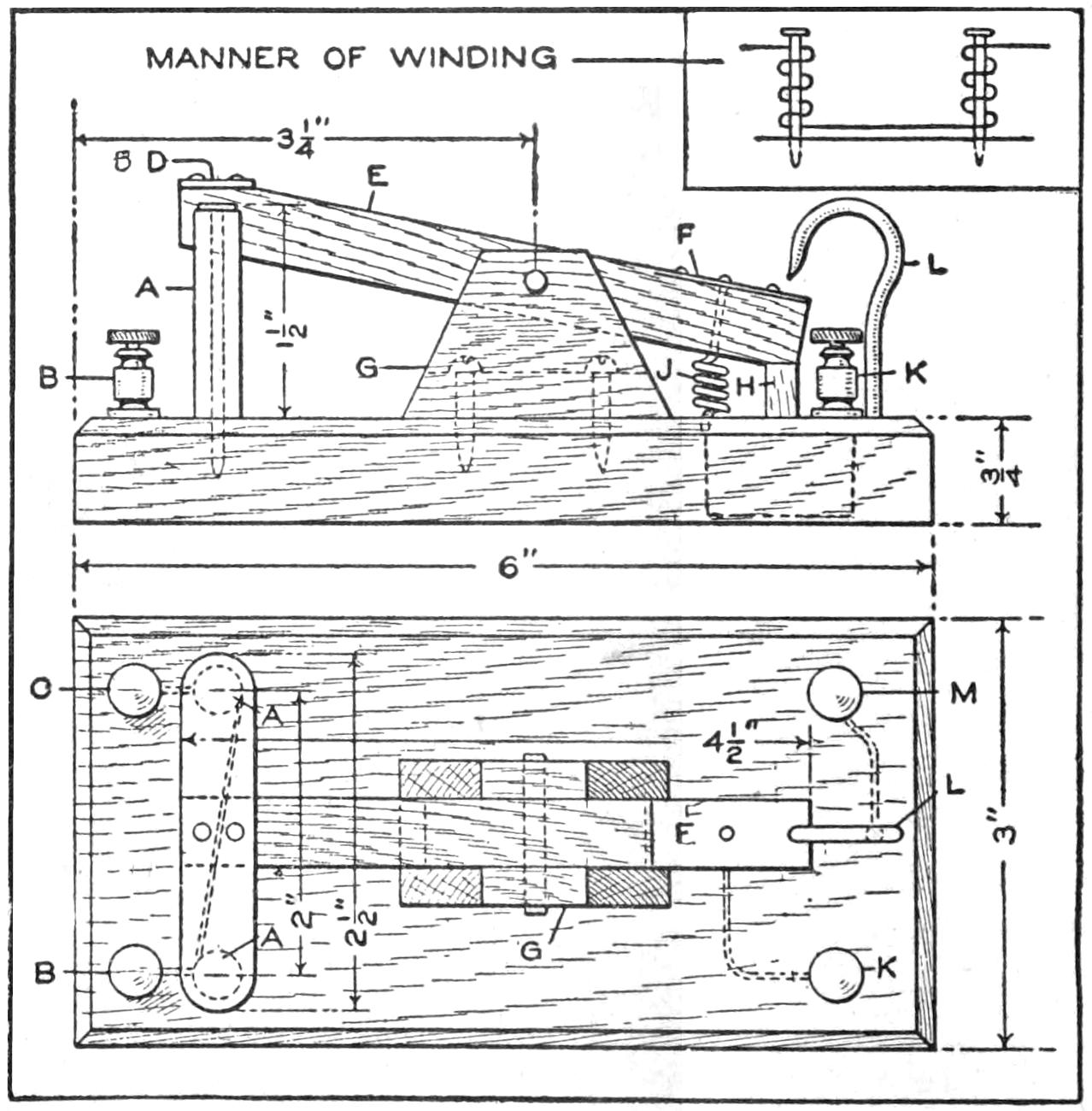
Nails, a Screw Hook, and Similar Common Materials, were Used in Making This Relay
The armature D is a piece of soft iron, ¹⁄₂ by 2¹⁄₂ in., screwed to the armature lever E, which is a ¹⁄₂ by 4¹⁄₂-in. piece of wood. A piece of tin is tacked to the opposite end F, and a ¹⁄₈-in. hole is bored through the lever, 2¹⁄₂ in. from the front end. Nail a wooden block, G, to the base, slotted to accommodate the lever, so that when the latter is pivoted in the slot, the armature will lie directly over the magnet heads. Fit a wooden stop, H, under the end of the lever, so that the armature is held ¹⁄₈ in. above the magnets, by a brass spring, J, connected to the tin, F, and the binding post, K, with copper wire. Arrange the brass hook, L, so it comes in contact with F when the armature bears down upon the magnets. Connect this hook to the binding post, M. When current flows through the magnets, the armature is pulled down and the contact of the hook, L, with the tin, F, completes a secondary circuit.—L. R. Hardins, Harwich, Mass.
¶A nutcracker may be used as a substitute for a pipe wrench or pliers, and its toothed handles grip round objects quite firmly.
[333]
A printing machine for “gaslight” papers, to be used in localities not equipped with gas or electricity and where printing is to be done after daylight, is shown in the sketch. The measurements given are only approximate, as conditions will determine its size. That shown is made as follows: First procure a 6¹⁄₂ by 8¹⁄₂-in. or 8 by 10-in. printing frame. Remove the brass clips from the pad and fasten one end of the pad to the frame, by a pair of small hinges, with the glass in the frame. Procure a box, about 12 by 15 in., by 8 in. deep, with one side open. Cut a rectangular opening through the 12 by 15-in. side a bit smaller than the printing frame, and secure the frame in place over the opening with screws. Saw a slot ³⁄₄ in. wide through the top of the box—the end nearest the hinged end of the printing frame pad—running it the full width and about 3 in. from the front.
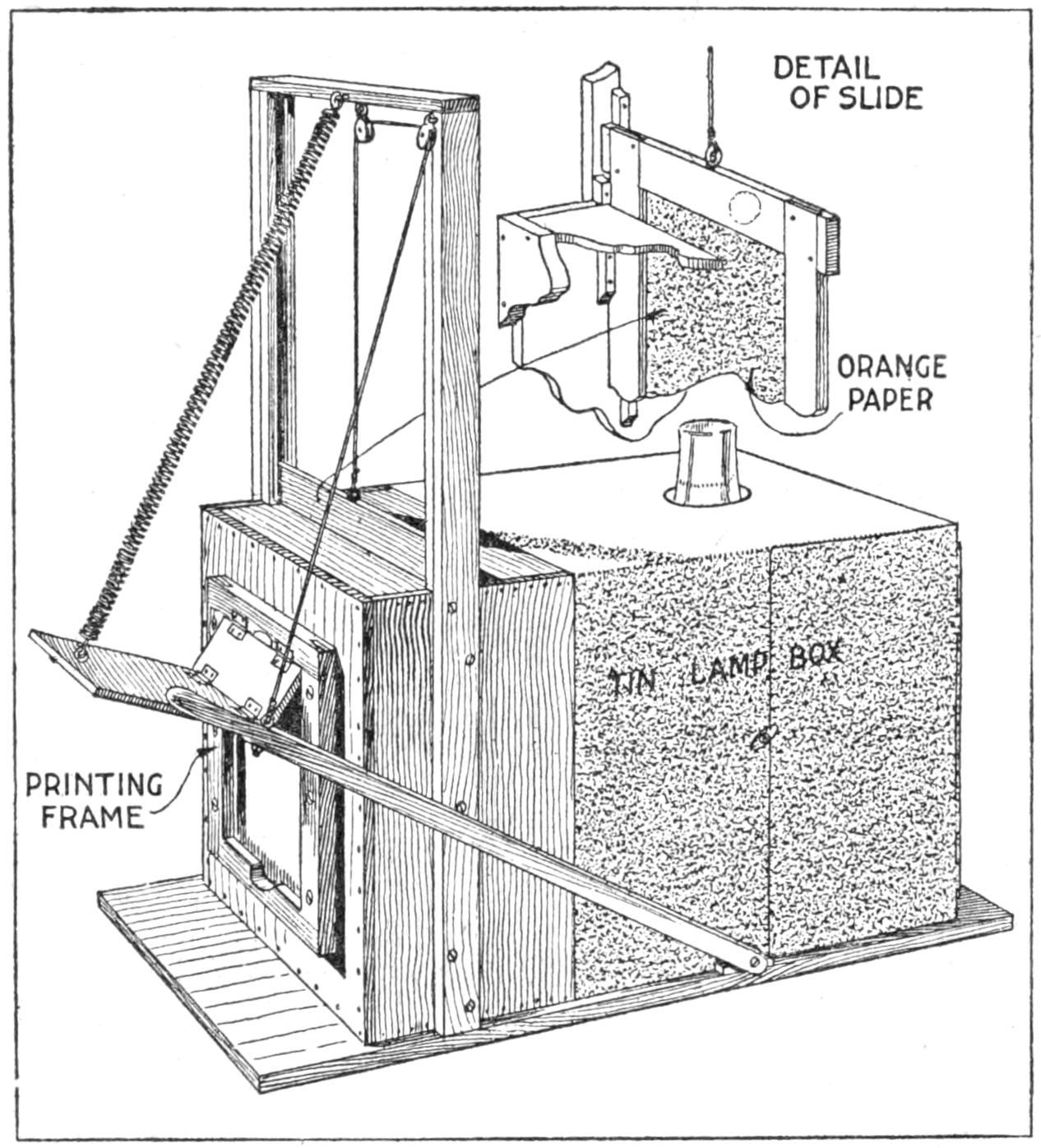
Photographic Printing may be Done Rapidly by the Systematic Use of This Machine
Nail cleats along the inside of each side of the box, placing them vertical and parallel, and about ³⁄₄ in. apart, so as to form a slide groove in conjunction with the slot. This groove is to receive a frame or curtain constructed of stock, 2 in. wide and ¹⁄₂ in. thick. The outside dimensions of the curtain are a trifle smaller than the inside measurements of the box itself. Cover the frame with orange paper, and when finished insert it through the slot in the top of the box. Build a frame as indicated, on the outside of the box. Along the inside of the uprights fasten cleats, thick enough to come flush with the ends of the slot. These serve to steady the curtain when raised. Make a suitable baseboard and secure the box to it. Then with sheet tin construct a lamp house extending from the back of the box and of sufficient size to accommodate a round-wick lamp. Leave an opening in the top to admit the chimney, provide holes for ventilation, and a door by which the lamp may be adjusted. When completed, paint the interior of the box and lamp house white, to intensify the printing quality of the light. Tie a piece of stout cord to a screw eye inserted in the upper end of the sliding curtain, lead it through two pulleys fastened as shown, and down to the hand lever. The latter is pivoted at the rear end by a bolt. Attach a spring to the lower end of the hinged pad on the printing frame. This holds the pad out of the way when not in use. A curtain-roller spring is suitable for this purpose.
To operate the machine, place the negative and paper in position, and, with the left hand, bring the pad down. Pull down the hand lever with the right hand, raising the orange curtain. When the required exposure is made, release the lever, shutting off the direct light. While nearly all light is shut out by means of the lamp house, the paper may be handled safely and easily by means of that admitted through the orange curtain. By systematic arrangement[334] and handling of materials, it is surprising what an amount of work can be turned out by the aid of this machine, especially if one person attends to the exposing and another to the developing.
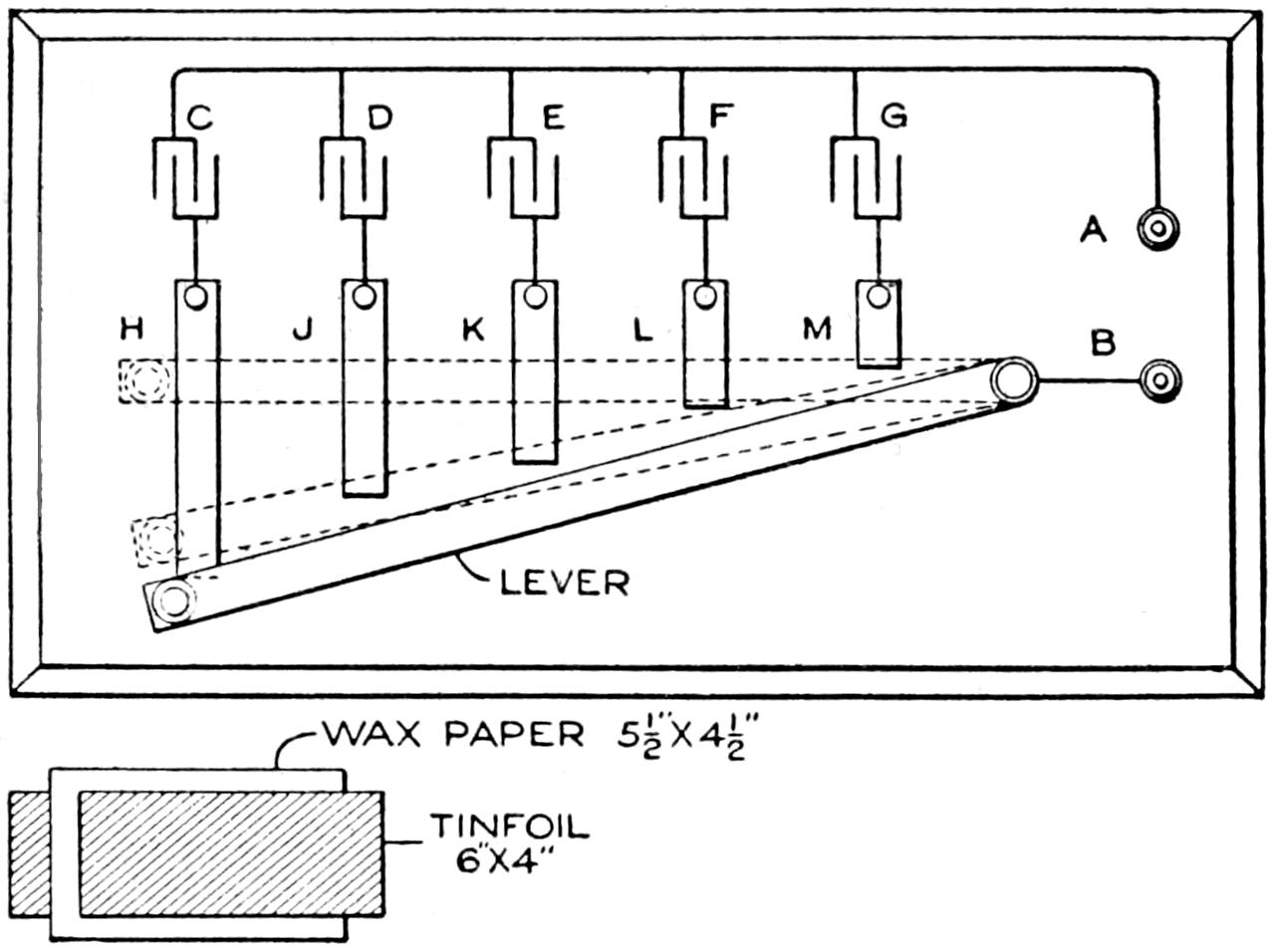
Diagram for a Small Variable Condenser
The condenser shown in the diagram combines the large capacity of a fixed condenser with the gradual capacity variation of a variable one. It is suitable for a wireless receiving circuit, or to shunt around the vibrator of an induction coil, by making the units considerably larger. It is made up of several fixed condensers, connected in parallel, a lever being the means whereby the capacity is varied. Five or more units may be used, each being a small condenser, built up of 10 sheets of waxed paper and nine sheets of tin foil. A convenient size for the tin foil is 6 by 4 in., and for the paper, 5¹⁄₂ by 4¹⁄₂ in. The latter should be a good grade of very thin linen paper and should be carefully prepared by dipping it in hot paraffin. The sheets of tin foil and paper in each unit are piled up alternately, allowing about ¹⁄₂ in. on each tin-foil strip to project beyond the paper for making connections. The pile is covered with heavy paper, and a heated flatiron is passed on the top of each unit until the paraffin begins to melt. Upon cooling, the units are compact.
The connections necessary are shown in the diagram. The condenser units C, D, E, F, G, each have one side connected to a common terminal A. The other sides of the condensers are connected to the copper strips H, J, K, L, M. They are ¹⁄₂ in. wide and ¹⁄₁₆ in. thick. A copper lever, ¹⁄₈ by ¹⁄₂ by 8 in., is pivoted on one end so that it will connect two or more of the condensers in parallel. The pivoted end is connected to the terminal B. The dotted line shows different positions of the lever. The apparatus is mounted in a wooden box.—Peter J. M. Clute, Schenectady, N. Y.
A candle may be lighted without the match flame touching the wick, as follows: Light the candle, let it burn a bit; then blow it out. A small column of smoke will rise from the wick. Touch the match flame to this, a little above the wick, and it will ignite, travel down, and relight the wick from the burning oil gas.
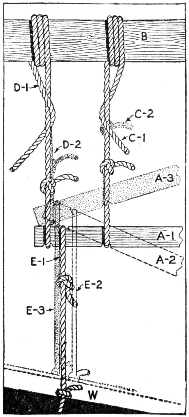
When block and tackle, chain hoists, or similar equipment are not at hand, the simple arrangement shown in the sketch is useful for lifting heavy loads. Make the lever A of a piece of 2 by 4-in. stuff, and cut notches into it for the ropes, as indicated. From a suitable support, B, fix the ropes C and D to the lever A at the proper notches, permitting the ends C-1 and D-1 to be drawn down and fastened to the floor or other support as required in raising the load. Fix[335] the rope E to the load W, and suspend it from the lever A at the proper notch by means of a loop, E-1. To raise the load, bear down on the end of the lever when it is in its original position A-1, bringing it to the position A-2. This will bring the lower rope to position E-2. Draw up the slack in rope D, to bring the loop to position D-2, and fasten it. Then lift the lever A from its position A-2, to the position A-3, and draw up the slack in rope C to bring the loop up to position C-2. The lower rope will be brought to position E-3. By repeating this process, the load may be raised gradually. The ropes may, of course, be of various lengths within the range of the support and the operators.
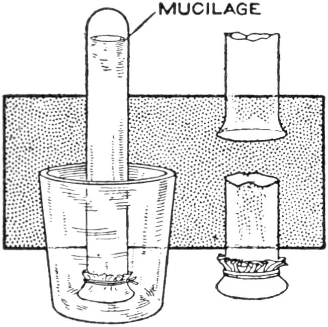
An ordinary test tube, about ⁵⁄₈ by 6 in. in size, may be made into a mucilage container and brush that economizes the material and does not get the fingers sticky. The end of the tube is covered with a piece of soft cloth after the tube is filled, as shown in the sketch. A convenient way to care for the device is to keep it in a small tumbler.—A. H. Carrington, Trenton, N. J.
An ice pick is often a source of danger, if left lying about the home, and should be kept at a place convenient to the ice box, where it will not be likely to cause injury. The small bracket on which the ends of the roller curtain are supported is a satisfactory holder for the pick. It may be fastened to the wall with nails, or screws, so that the pick may be suspended in the center hole.—Robert J. Donnelly, Cincinnati, Ohio.

A swing, so durable that it has become a virtual landmark, was made from a long, straight hickory sapling suspended from the limb of a tree. The sapling was split part of its length, as shown in the illustration, and a bolt put through it to prevent the upper portion from cracking. The lower end was smoothed off, so as not to injure the hands, and mortised through a slab of wood, as shown in the detailed sketch. A safe hook from which to suspend the swing is suggested. It is made from a bolt fixed through the limb and curled at the hook end so that the swing may be taken down in bad weather.—Hubert Kann, Pittsburgh, Pa.
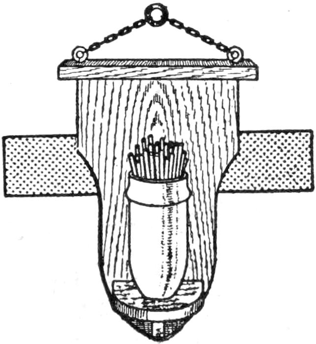
The match safe shown in the sketch was made by a worker in a munitions plant. The container was shaped like a small cannon shell and was set into a bracket supported on a prettily grained board, stained and varnished, and supported by a chain.—J. H. Moore, Hamilton, Can.
[336]
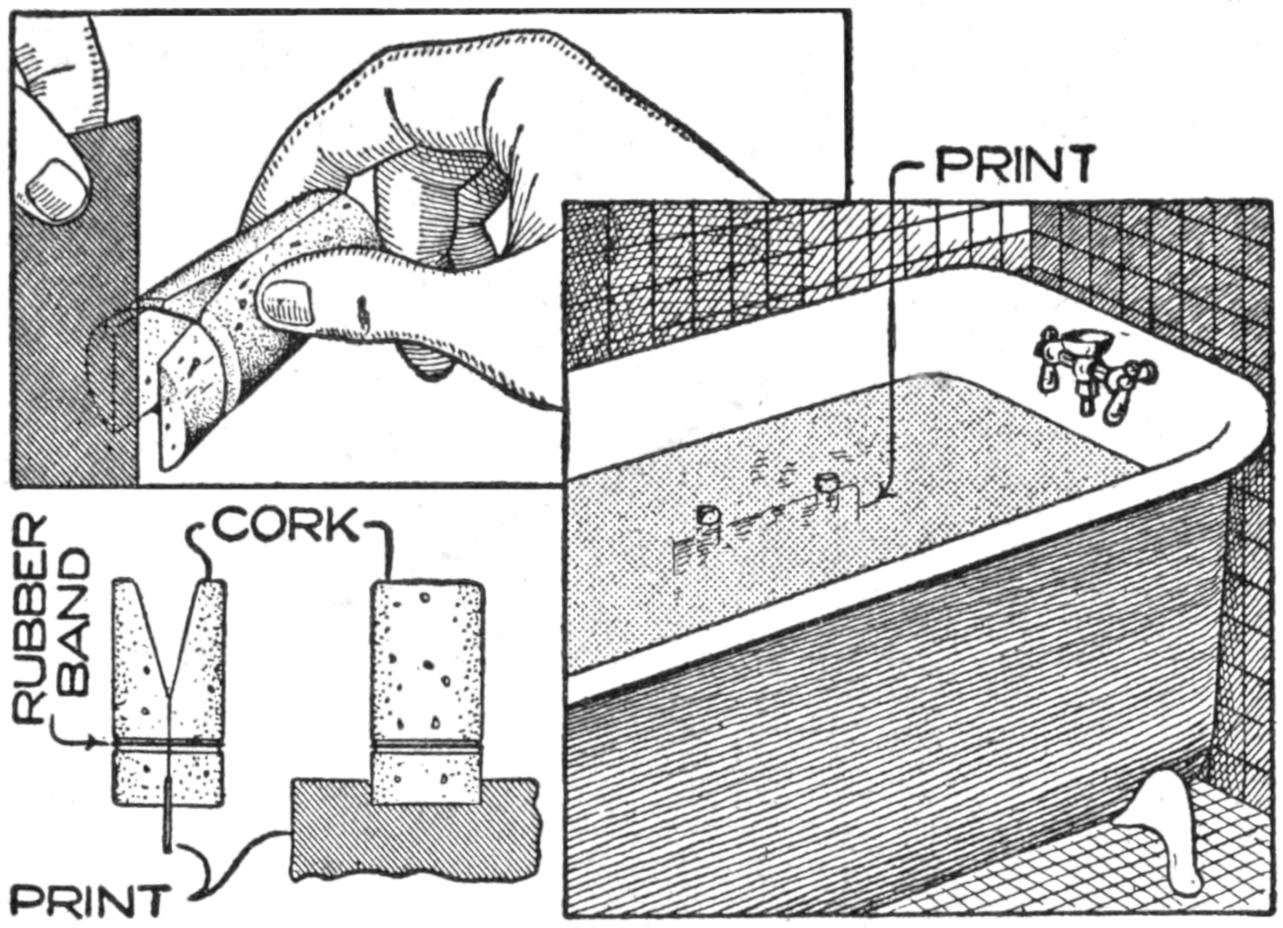
The Cork Clips Hold the Bromide Print in the Water in a Vertical Position
The difficulty of washing bromide enlargements of the larger sizes has always made the amateur hesitate to undertake much of this kind of work. The developing and fixing can be done with comparative ease, because of the facility with which the print can be kept moving in a tray that is smaller in size than the print itself, but washing is such a long process that one’s patience is exhausted before the hypo is completely eliminated. Continuous handling of a print for 30 minutes is tedious work. This objection can be overcome in the simplest and most efficacious manner, as follows:
Procure some large corks of the best quality and in each cut a groove completely around it, near one end, to serve as a retainer for a rubber band; then cut the cork lengthwise through the center, and cut a wedge-shaped piece from the center toward the end opposite the one where the groove was cut for the rubber band. After placing a band in the groove of the proper size the combination will work similarly to an old-fashioned spring clothespin.
If two of these are snapped on the edge of a bromide print, this can be dropped into a bathtub or laundry tub for washing. The corks will cause the print to float vertically in the running water. By this means a number of prints can be washed at a time without any danger of their sticking together or becoming wrinkled or cracked in the bath.—Contributed by T. B. Lambert, Chicago.
To make the most effective use of a miter box, it must be fastened solidly to a base, but if fastened to the workbench top it is in the way when not in use, and it is a nuisance to fasten and unfasten the box every time it is used. To avoid the changing, I mounted the miter box on two pieces of 1 by 3-in. stock, about 2 ft. long. These pieces were placed on the bench top, at right angles to the front edge and with their centers as far apart as the two pairs of legs on the box. The box was placed on the front end of the pieces, with the back parallel to the front of the bench, at right angles to the pieces, and was fastened to them with screws. The other end of each piece was fastened to the bench top with a hinge.
This fastened the miter box firmly to the bench top, but in such a way that I could tip it up and back against the wall, or other support, where it was out of the way but ready for use immediately. To stiffen the frame, I placed a cross brace between the two pieces, making it in the form of the letter H.—Contributed by L. C. Burke, Madison, Wisconsin.

Blowpipe Connection to the Ordinary Illuminating-Gas Main for Hard and Soft Soldering
Every experimenter who has a gas connection within convenient distance of the workbench should provide a 4 or 5-ft. length of ¹⁄₄-in. rubber tubing, terminating in a brass tube through which air may be blown in order that a clear blue flame may be available for either hard or soft soldering. The brass tube should be 4 or 5 in. long and fitted at one end with a removable nozzle having a ¹⁄₁₆-in. hole in it. A hole is then drilled in the side and a piece of smaller brass tubing, bent as shown in the sketch, is soldered in place for the air supply. A piece of soft-rubber tubing about 1 ft. long is then provided and one end slipped over[337] the projecting end of the air pipe and the other fitted to a hard-rubber, or amber, mouthpiece. By regulating the gas supply and blowing to the proper degree, a pencil of blue flame may be produced, anywhere from 1 to 4 in. long. For heating large surfaces, the nozzle tip should be removed.
This method of soldering not only makes a better connection than the usual copper, but is instantly available and does not disarrange the several pieces where, as is often the case, it is not practicable to pin or hold them in place.
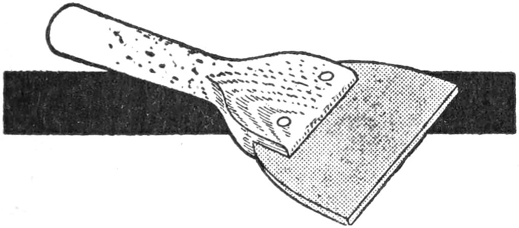
A Dish Scraper Made of a Piece of Rubber Inserted in a Wood Handle
Housekeepers will find the scraper shown to be silent and more rapid than a knife for cleaning dishes. It consists of a handle cut from a piece of straight-grained wood, with a kerf sawed in the wide end to a depth of ³⁄₄ in., into which a piece of sheet rubber is inserted. The rubber may be cut from an old bicycle-tire casing and is fastened with two or three brads driven through the handle. The ends of the brads are bent over or riveted. The edge of the rubber should be made straight.—Contributed by H. S. Craig, Rushford, Minn.
A public-school auditorium was used for playing basket ball, and the lights were protected as shown. Wire waste-baskets were fastened to pieces of board, which in turn were nailed to the ceiling around each lamp. As it was desired to provide a way to ventilate the room, an opening was cut in each board around the lamp base, providing fan-shaped cut-outs covered with galvanized metal of the same design, to make a way to open and shut the ventilator. The air passed up into an attic.
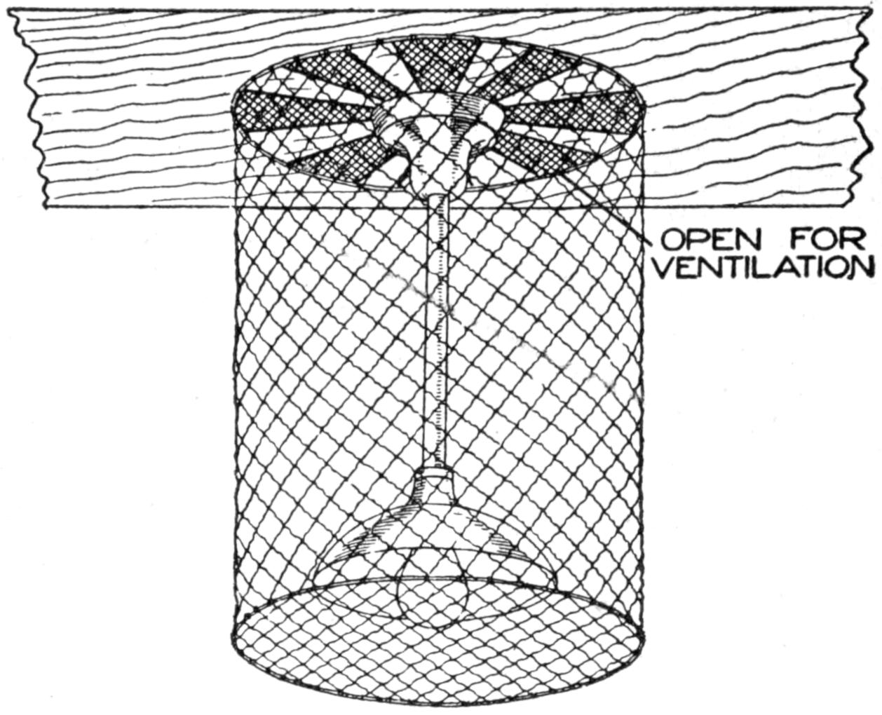
Wire Wastebasket Fastened around a Light to Protect It for Basket-Ball Games
The goals, which were old blackboards, were fastened between the posts that supported the ceiling. Two iron rods, one above the other, were clamped with bolts to the posts, and the boards were bolted to the rods.—Contributed by Frank C. Svacha, McKees Rocks, Pa.
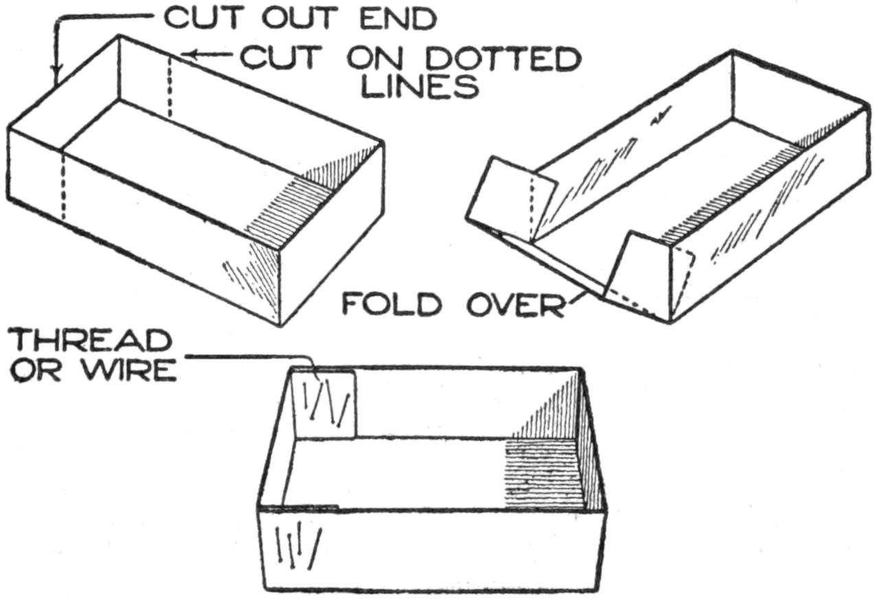
Shortening a Box by Bending Up the Bottom after Removing the End and Cutting Down the Sides
If a pasteboard box happens to be too long for a special purpose it can be shortened as shown. The sides are cut down to the bottom and the end removed. The bottom is then bent up on a line between the places where the sides were cut down, to form a new end for the box. The joining parts are then held with a thread or wire fasteners.
[338]
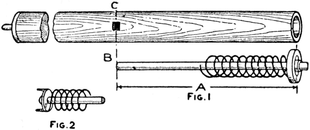
Fig. 1
Fig. 2
Fix the Loosened Spring into Place and the Roller Is in Working Order
Springs of window-shade rollers, which usually break at the tin cap by which they are fastened inside the rod, can be quickly repaired in the following manner:
Remove the ferrule and dogs from the end of the roller and pull out the stick to which the spring is attached. Measure the length of the stick A, Fig. 1, on the roller, and at C cut a small square hole through to the hollow center. Remove the metal cap thus exposed. Fix the cap on the end of the stick at B and fasten the spring around one point of the metal cap, Fig. 2. Insert the stick into the roller and tap it gently, driving the cap points in; then replace the ferrule and dogs, and the roller is in condition for use.
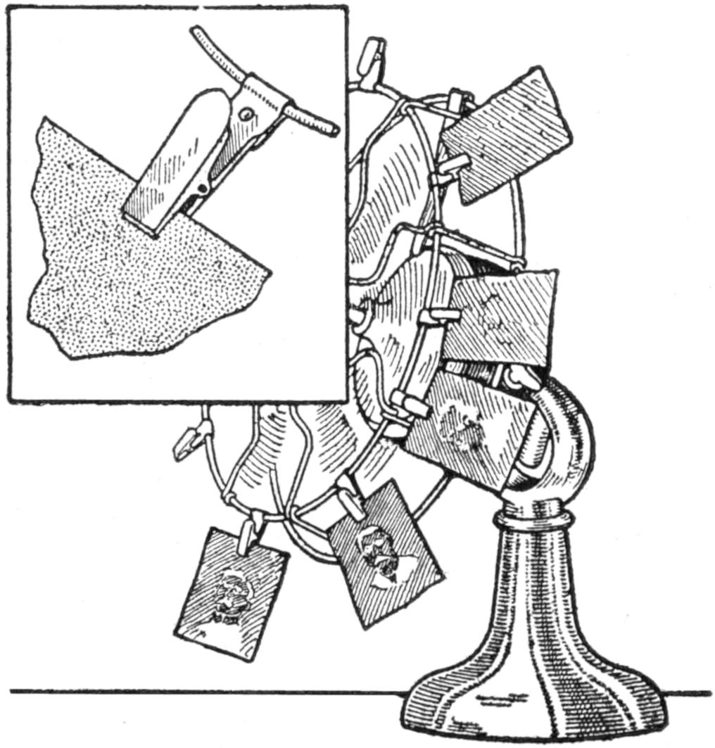
The Current of the Fan Dries the Films Rapidly
Waiting for photographic films to dry is often tedious, particularly when the photographer is in haste to see the results of his efforts at picture taking. The method of drying the films shown in the sketch will aid materially in the process. The films are held by small spring clips attached to the wire frame surrounding the fan, and when the current is turned on, the films are blown away from the fan and held suspended in a diagonal position.—Contributed by W. J. Clausius, Chicago, Ill.
Surfaces may be coated readily with bronze powder by applying a thin coat of shellac and quickly dusting the powder over it. Speed is important in dusting on the powder, as if the shellac hardens it will not hold the bronze. Surfaces which have been bronzed in this way may be polished if additional coats of shellac or varnish are applied over them.
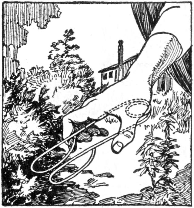
Difficulty in removing small weeds around plants in the garden may be overcome by the use of a forceps made of a piece of wire, as shown in the illustration. The wire is formed into two loops by which the weeds are grasped, and the portion held in the hand is bent to form a circular spring. Its tension may be regulated so that the hand will not be tired in using the device.—Contributed by Irving McEwen, New Westminster, B. C., Canada.
Injury to pictures from dampness of walls may be prevented by fixing small disks of cork to the lower edge of the frame so as to form a contact with the wall only at the cork. This permits a current of air to pass between the wall and frame.
[339]

Many devices have been made for developing and fixing roll films. There is the simple wholesale method of the professional who hangs a weight on one end of the film and lets it down in a deep tank of developing fluid where it hangs submerged from an upper support until the development is complete. Then the support, the film, and attached weight are removed, dipped into a similar tank of running water, then to another tank of fixing solution, and subsequently washed and dried.
This is the only practical plan where there are many such films to be handled simultaneously, but the amateur who has only one or two rolls a week cannot afford the tanks, the space, nor the expense incident to such a method. The film is usually drawn back and forth through a developing solution placed in a tray, and after the development has proceeded far enough, the same process used in washing, then the hypo solution, and finally through the last washing for about 20 minutes, all making a tedious process.
Some amateurs and a few professionals who but occasionally develop roll film use a mechanical device that rolls the film into a light-proof package which is inserted in a metal tank for development and subsequent fixation. This is a standard process, the apparatus being on sale at all supply houses, but it has its drawbacks.
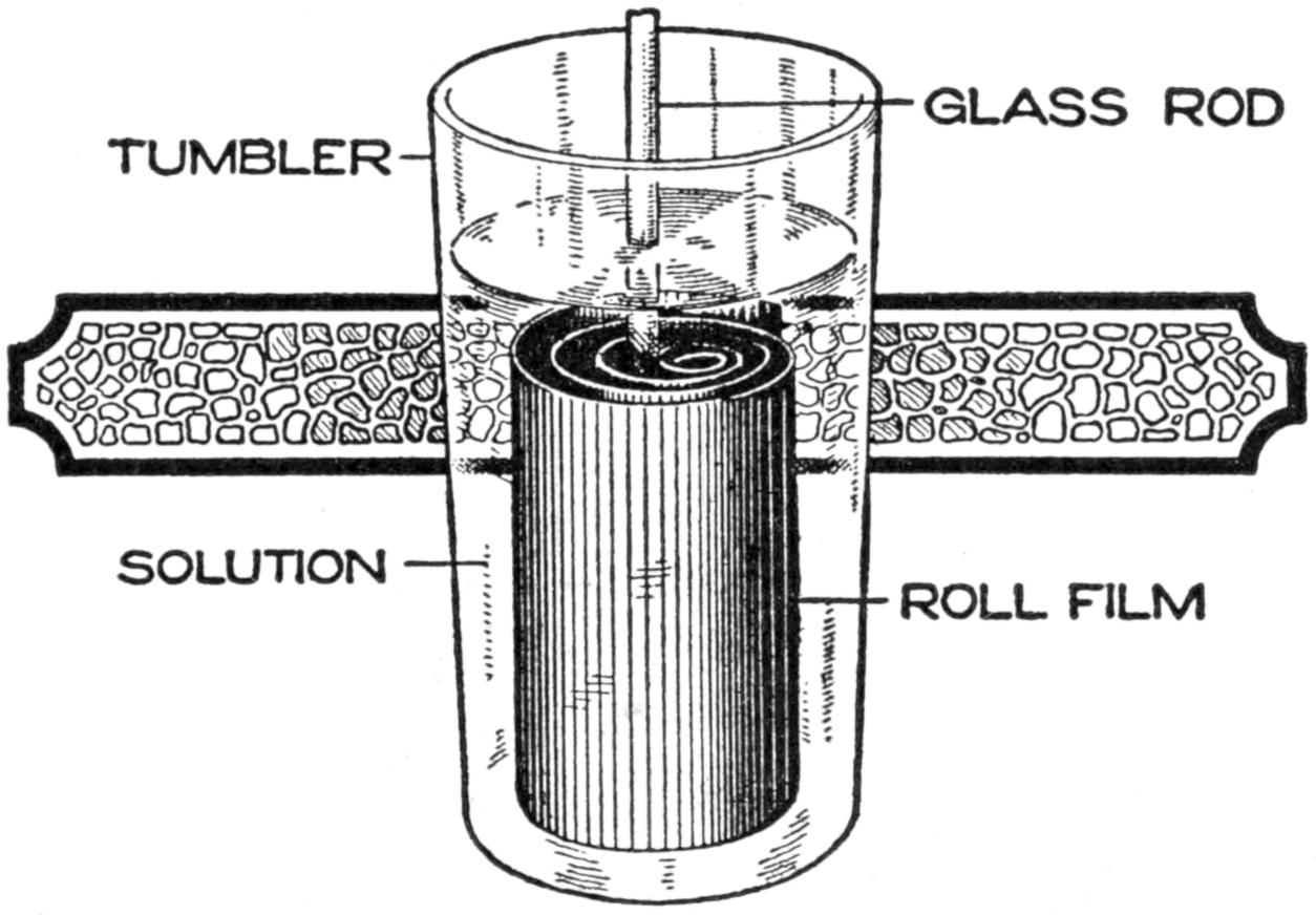
An Ordinary Drinking Glass Used for Developing Roll Films
The following method is not only simple but perfect in its operation and requires no special apparatus, only a tumbler or lemonade glass, and an ordinary lead pencil for its operation. A glass rod is preferable to the lead pencil, and it is also convenient to have a deep tin cup, or similar device, to cover up the lemonade glass and make it light-proof, should it be desirable to turn on the white light in the dark room.
Pour enough developing solution into the glass tumbler to cover completely the roll of film when it is standing on end. In the dark room open the film roll, remove the backing paper and the paper ends on the film, run it through clear water until it is thoroughly and uniformly wetted from end to end, and drop it endwise into the tumbler of developer. Immediately insert the pencil or glass rod into the center of the roll, and with a rather quick circular motion, move the rod around so that it will quickly pass between the several convolutions of the film and thus distribute the developer all over its surface. Repeat this operation at once, then again in a few seconds, then in 15 or 20 seconds, then in 30 seconds, then[340] in 1 minute, and so on, with greater intervals of time. If a 20-minute developer is used, it will only be necessary, at the latter part of the development, to separate the layers every 2 or 3 minutes.
When the development is complete, pour off the solution and rinse in the same glass by letting water run through it while passing the pencil or glass rod between the layers several times. The water may then be drained off, and the glass filled with the fixing solution. While the film is fixing, the glass rod should be passed between the layers several times to renew the solution in contact with the film.
It will be seen that at no time after the first washing is it necessary to handle the film, so that damage to the film and staining the fingers are entirely eliminated. Further than that, no apparatus is tied up in the operation, and if a light-proof cup is at hand, the developing tumbler may be covered between the operations of separating the layers of film, and the white light of the dark room can be turned on for further operations.
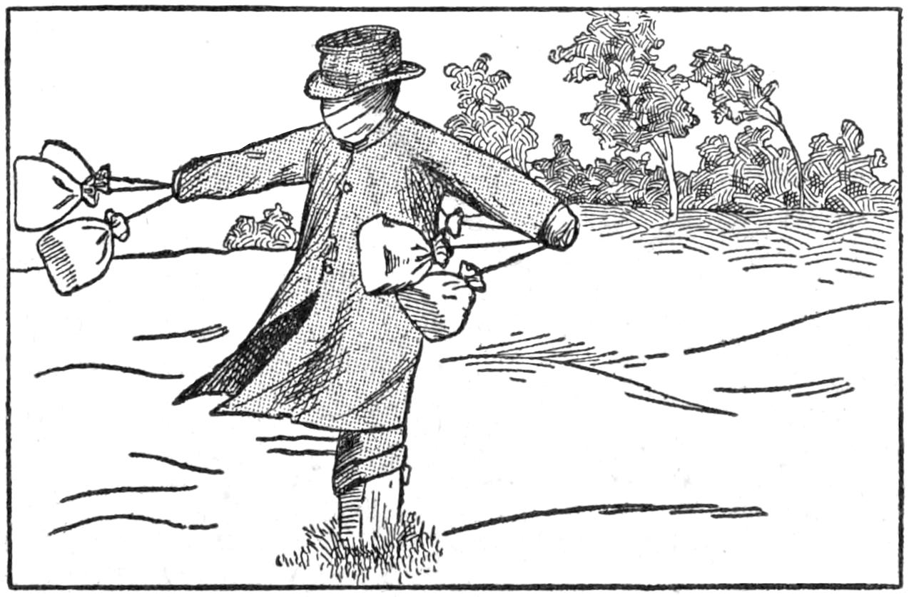
Scarecrow with Swinging Paper Bags on the Arms in the Place of Hands
The ordinary ragman used as a scarecrow can be made more effective by adding to it something to make it move, or some part that flutters in the wind. This can be accomplished in one way by blowing up paper bags to expand them to their full extent, tying the openings as if they were filled with some commodity for the household, and fastening them to the arms of the dummy as shown. These will swing and flutter about in a way that will materially aid in scaring away the birds that damage the crops.
Serving and card trays can be made very beautiful and artistic with the use of butterflies, natural grasses, and the fluffy part taken from the milkweed pod, formed to make a natural scene beneath the glass bottom of the tray. If an old tray is to be used, remove the old panel, or painting, beneath the glass bottom, and clean the glass thoroughly. Lay it upside down on a flat table top and carefully place on it a cluster of grass, or weeds, or some botanical specimens, that are well dried. Arrange the dried butterflies in a natural way around the grasses with their backs, or tops of the wings, facing out, or on the glass.
The silky down of the milkweed seed, with the seed removed, is used to cover the specimens and grass, which forms the most delicate background possible. It is laid on quite thick at the bottom of the scene, gradually thinning it toward the top. Be careful to see that the fibers of the down are placed so that they will radiate from the bottom of the grasses to the outer edges. A piece of white, pearl, or gray cardboard is then placed on this background, and another glass or board back is sealed tightly over the whole with glue or wax.—Contributed by Joe V. Romig, Allentown, Pa.
Lard buckets are the most easily obtained and the most satisfactory of utensils in which to pack food, or cook for a small picnic or camping party, but it is very difficult to remove the odor of the lard. This may be easily accomplished by boiling the grounds from the coffeepot in the bucket with about one pint of water.
[341]

Parlor cue alley is really a game of bowling except that it is played on a small raised board, and, instead of throwing the balls by hand, an ordinary billiard cue is used, the balls being about 1¹⁄₄ in. in diameter. The automatic feature of this new game saves the time usually required to set up the pins, and assures that they will be set absolutely true each time.
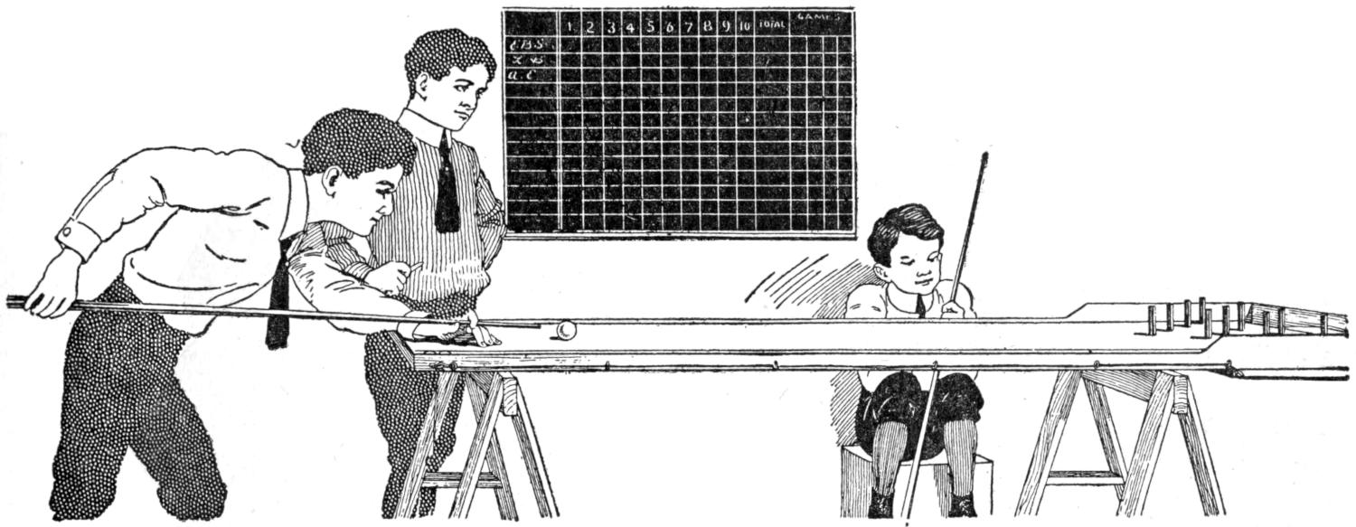
A Cue is Used to Shoot the Ball on This Alley
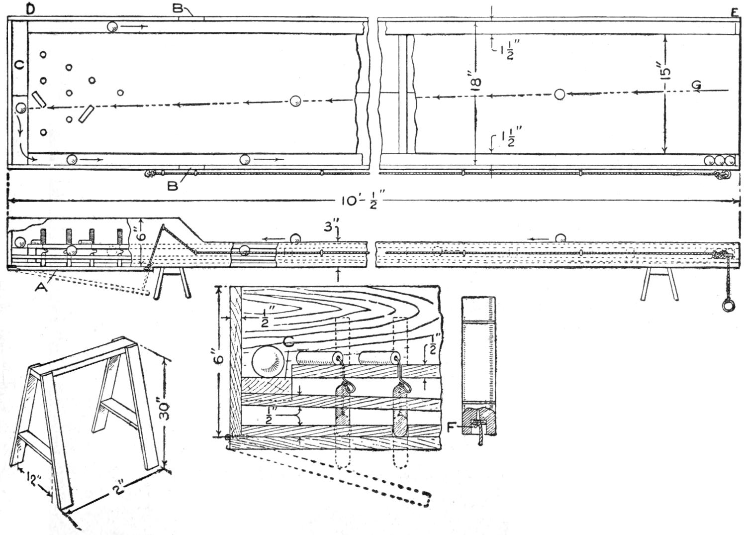
The Alley Board with Its Attachments
To build this alley, first procure three planed boards, hard wood preferred, though they are more difficult to work; two, 10 ft. long, 9 in. wide, and ¹⁄₂ in. thick, and the other, 10 ft. long, 15 in. wide, and ¹⁄₂ in. thick. Place the first two boards side by side and fasten them with cleats, the first cleat being placed 18 in. from the end to be used for the pins. The cleats should[342] be of ³⁄₈ or ⁷⁄₈-in. material and cut as long as the upper board is wide, or 15 in. These are placed on top of the lower boards, or between the two. By placing the first one 18 in. from the end, clearance is obtained for the trap A. The other board is placed on the cleats and fastened, after it has been centrally located, with screws from the under side. The screws must not come through or the surface of the upper board be marred in any way so that the balls cannot roll freely. The difference in width of the lower board and the upper one provides 1¹⁄₂-in. clearance on each side as grooves for the return of the balls.
Inclose the alley with boards, 3 in. wide and ¹⁄₂ in. thick, to the point B, and from there around the pin end with boards, 6 in. wide. The upper board should be cut to such a length that a space of 2 in. at the end C will be provided. Into this space is fitted a block of wood, about ⁷⁄₈ in. thick, having its upper surface slightly pitched toward the sides of the alley to start the balls back to the front of the board. From the ends of this block two strips, 1¹⁄₂ in. wide, are fitted into the side grooves, from D to E, on an incline, to return the ball after each shot.
The location of each pin is marked on the end of the upper board, and small holes are drilled just large enough to admit pieces of stout cord, like a fishline, to pass through freely. The pins are made of hard wood, carefully balanced, so that one end will not be heavier than the other. The lower end of each pin is drilled to make a recess, F, in which the cord is fastened with a screw or nail. Holes are bored through the bottom board, ³⁄₈ in. in diameter, to correspond to the 10 small holes made through the upper one. Lead weights of about 2 oz. are fitted in the holes and attached to the strings from the pins. The ends of the weights should extend about ¹⁄₂ in. from the under side of the alley.
Attach a board, 18 in. square, with hinges to the end of the alley so that it will hang under the weights. A stout cord is run along the under side of the alley to the front end through screw eyes, and attached to the swinging board. By letting the board swing down the weights are released and they draw the pins into a standing position, accurately set for the next break. When set, the line is drawn, and the swinging board pushes the weights up and releases the pins.
The balls used are made of hard wood, and, if it is not desirable to make them, they can be purchased from a toy store. They are 1¹⁄₄ in. in diameter. Each player has three shots. The ball is placed on the spot G and shot with a billiard cue, the object being to knock down as many pins as possible; the score is kept as in bowling.
Horses can be made of metal and wood, as shown, for holding the alley at the proper height. The alley can be used on a large table, but horses are more convenient.
The effect of this trick is as follows: The performer first exhibits a small table, about 2 ft. square, the top of which is covered with black velvet. He requests the loan of a Derby hat and a handkerchief, then takes an ordinary glass, filled with water, and places it on the table top, covers it with the handkerchief, and sets the hat on top of the glass. He then withdraws a short distance, and at a command, the glass appears to pass slowly through both handkerchief and hat until the hat rests on the table top. The hat is then taken up and is handed to the owner, who finds the glass of water in the hat.
While this is seemingly impossible, the effect can be easily accomplished and the necessary apparatus can be made up cheaply if a table of suitable size can be had, although a kitchen table may be used if so desired, but a table about 2 ft. square is preferred, because it can be easily carried. The table is prepared as follows: Procure a block of wood, about 2 in. square and 1¹⁄₂ in.[343] thick, and glue it to the under side of the table in the center. Bore a ¹⁄₄-in. hole through both the table top and the block of wood. The top of the table must be covered with some black cloth, such as velvet. Using the hole bored as a center, cut out a piece of the table top to correspond with the diameter of the glass to be used, and about ¹⁄₈ in. deep, fit into this depression a piece of round sheet brass. Procure a ¹⁄₄-in. rod, about 6 in. long, and fasten the brass disk to the end of it so that the disk will fit into the round depression when the rod is run through the hole in the table top and block. The other, or lower, end of the rod is filed flat, and a small hole is drilled through it, the edges being smoothed to receive a thread. The top of the brass disk is covered with the same material as is used for covering the table top. This will make it appear to be one piece covering the table top. Fasten a strong black thread to one corner of the table top on the under side, and run it through the hole drilled through the end of the rod, then over a small window-curtain roller fastened into the opposite corner of the table top, where the thread is run down a table leg and through another pulley out under a rug or the floor to an assistant where the thread will not be seen. The metal disk can then be controlled without any apparent power. If the rod extends under the table too far, tape some velvet or fancy cloth around the table edge to cover it.

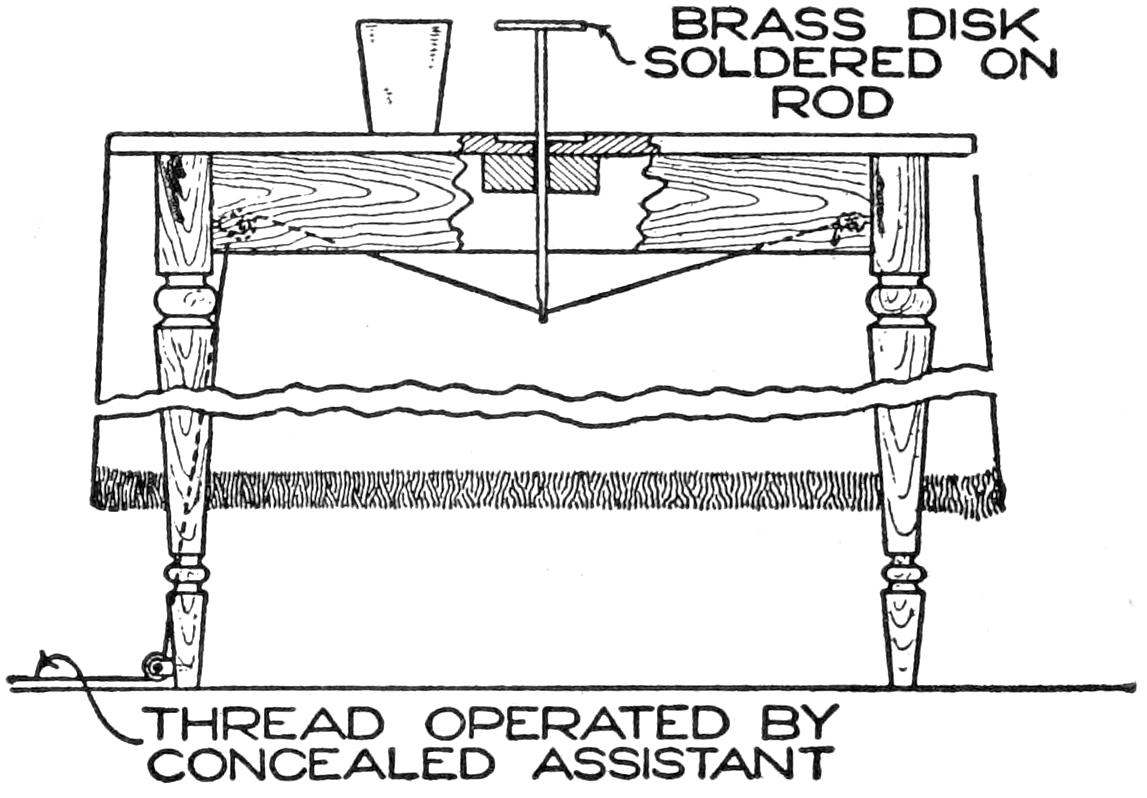
Apparently the Glass Filled with Water Passes Up through the Crown of the Hat and is Taken from it When the Trick is Completed
To begin the trick, the performer exhibits the glass of water, then sets it on the table just back of the disk, and in placing the borrowed handkerchief it is put on the disk rather than the glass. As the handkerchief is held in front of the glass the assistant pulls the disk up; thus the handkerchief is placed on the disk and the glass of water is left uncovered just behind it. The performer then starts to put the borrowed hat on the glass, crown up, and when, seeing his mistake, he apologizes, turns the hat over, and in doing so picks up the glass of water and places it in the hat. The hat is then set on the disk with the crown down. In turning the hat the glass is taken up with the first two fingers of the right hand. When the hat is raised, the glass is also raised with it, and while doing this the hat is slanted so as to hide the glass. In turning the hat over, the glass is brought into it. This is quite hard to explain, but a little practice will enable the performer to make no mistake. When the hat is placed on the disk the assistant slowly lets the disk down. It is very necessary to let the hat down slowly, as a sudden jerk is apt to tumble the hat over and spoil it as well as the trick. When the hat comes to rest on the table top, it is removed and handed to the owner with the glass of water in it.
[344]
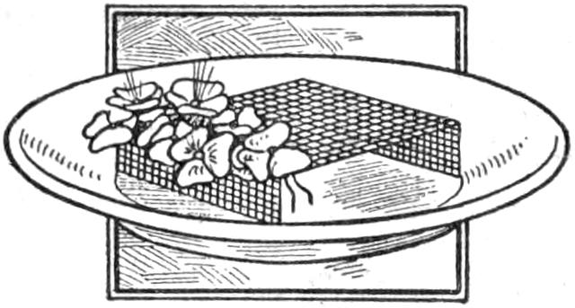
Pansies, violets, or other short-stemmed flowers cannot easily be shown to advantage in a table centerpiece unless properly supported. By placing a frame of wire mesh in the dish, as shown in the sketch, the stems of the flowers may be set in the openings, giving a neat and effective display.—Victor Carpenter, South Bend, Ind.
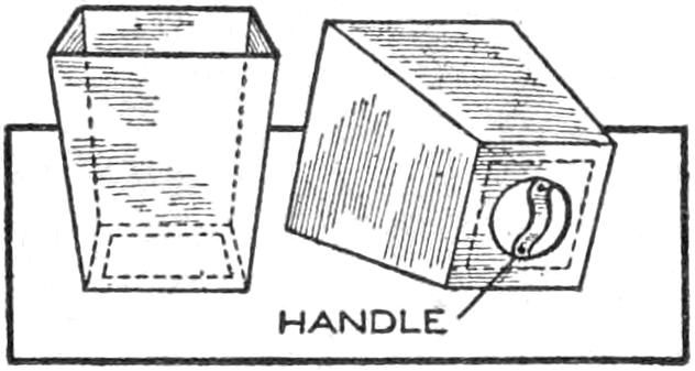
In order to avoid handling paper and other material which sometimes sticks in a wastebasket, I arranged a false bottom in the receptacle, as shown in the sketch. A hole was cut in the bottom of the basket and a square board, nearly as large as the bottom, was fitted over it, and a leather handle provided. The basket may be emptied quickly by forcing out the false bottom, without the hands touching the contents.—Harold Laughlin, Reading, Michigan.
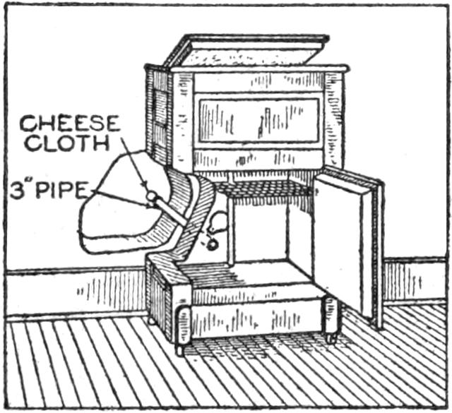
By fitting a 3-in. pipe into the lower part of a refrigerator so that a draft of cool air from outdoors is available in cold weather, it may be used without ice for a considerable part of the year. The top is left open slightly, and a piece of cheesecloth is tied over the outside end of the pipe, to prevent dust from entering. A tin shutter is placed on the inside of the refrigerator to close the pipe in extremely cold weather. This arrangement has proved quite satisfactory for the winter storage of food.—R. R. Dowsley, Prescott, Canada.
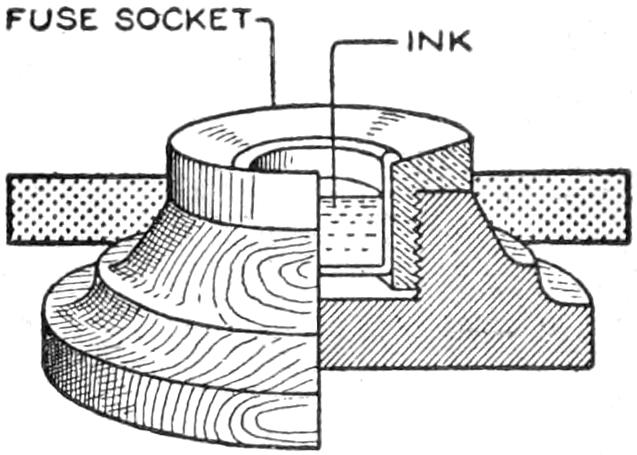
Workers in the munitions industry frequently devise small useful or ornamental objects in imitation of, or from, discarded parts on which they work. The inkwell shown in the sketch was made from a rejected fuse socket of a shrapnel shell. It was fitted with a glass container and fastened into a wooden base.
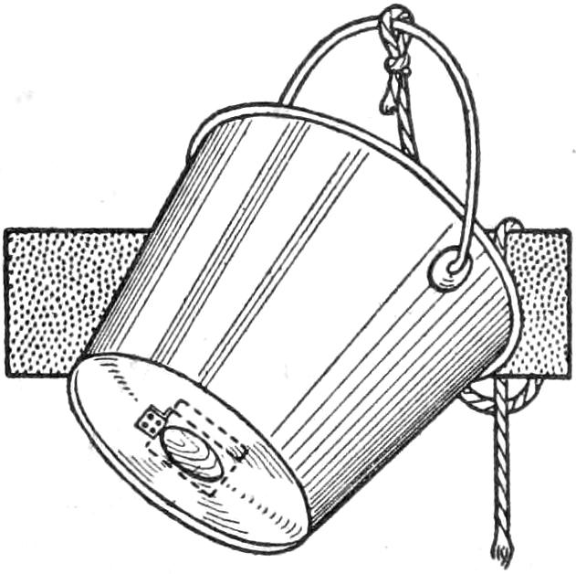
An ordinary pail may be converted into a convenient device for dipping water by fitting a valve into the bottom, as shown in the sketch. Fasten a piece of soft leather to the bottom of a block, 3 in. square, and fix this to the bottom of the bucket by means of a small hinge. By pushing the bucket bottom down into the water, the latter rises up through the valve until the bucket is full. By lifting it the valve is closed. This device fitted to a tall milk pail is especially convenient.—R. S. Matzen, Fort Collins, Colo.
It is awkward to shine one’s shoes with a long strip of cloth as is done by a shoe shiner to produce a high polish. An effective substitute method is to suspend from the wall a strip of cloth, about 5 in. wide, doubled to a length of 30 in., and rub the shoes on it before putting them on.
[345]
The performer calls the attention of his audience to a cabinet mounted on short legs and having doors in the front, back, and top. The back door is opened, then the top and front, and an arm is thrust through to show that the cabinet is empty and without double doors or double walls. The performer also puts his wand beneath the box to show that there is no deception there. The doors are then closed, except the top, and reaching down, he takes out any number of articles, from handkerchiefs to rabbits, and then the front door is opened to show the box is empty, but upon closing the front door again, he is still able to produce articles until the supply is exhausted. Wonderful though this trick may appear, it is very simple, and if a person is handy with tools, it can be made from lumber taken from a packing box.
To make the cabinet, nail together, in the shape of a rectangle, two pieces, 16 in. long, 14 in. wide, and ¹⁄₂ in. thick, and two pieces 14 in. square and ¹⁄₂ in. thick. To one of the latter pieces fasten four legs, one at each corner. In the opposite piece, or the top, make an opening in the center, 8 in. square. This opening is covered with a door 8¹⁄₂ in. square, supplied with a knob to open it easily. A piece, 16 in. long and 14 in. wide, with an attached knob, is hinged to the front, for a door; also another for the back hinged in the same manner and with a knob. In the back there is a cutout made, 9 in. long and 7 in. wide, in the center. In this opening a swinging box is hung to hold the articles taken from the cabinet. The swinging box is made of two pieces, 9 in. long and 7 in. wide, and two pieces about ¹⁄₂ in. larger each way, nailed together on ends, cut triangular. This box is hinged in the opening so that it will swing in or out as desired and show a panel on either side of the door. The front door should have a panel nailed on each side of equal size, to make both doors appear alike.
After loading all the things desired to be shown in the triangular box, start the trick by pushing this box into the cabinet and showing the outside; then open the back, and in doing so, push the triangular box out as the door swings back and away from the audience. This shows that there is nothing to be seen but the panel. Open the front door and top, and the cabinet will appear empty. Close both front and back doors, and in making this change, push the triangular box in, and begin to take the things out through the top door.
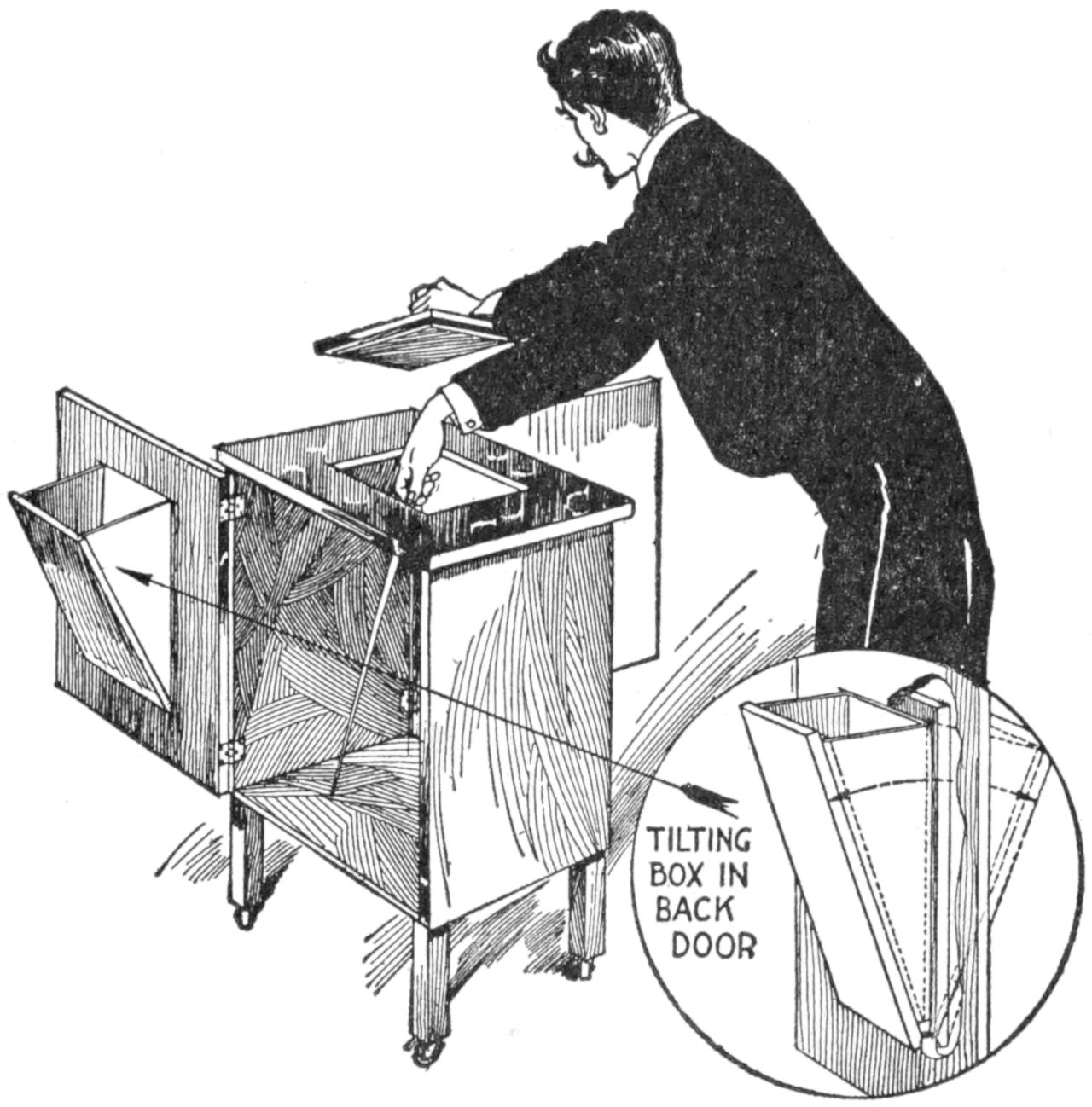
Open the Front Door and Top of the Cabinet and It will Appear Empty
By careful construction the cabinet can be made so that the doors will open freely and the triangular box swing easily so that it will not be seen in operating it. With a clever performer this trick is without an equal, as many variations can be made in the performance.
When a hole in a piece of steel, iron, or brass is being countersunk, the drill usually chatters, making the countersink rough. Where a smooth hole is required, it is best to make the countersink first and drill the hole afterward. By doing so the hole will be perfectly smooth.—Contributed by Chas. G. England, Washington, Pa.
[346]
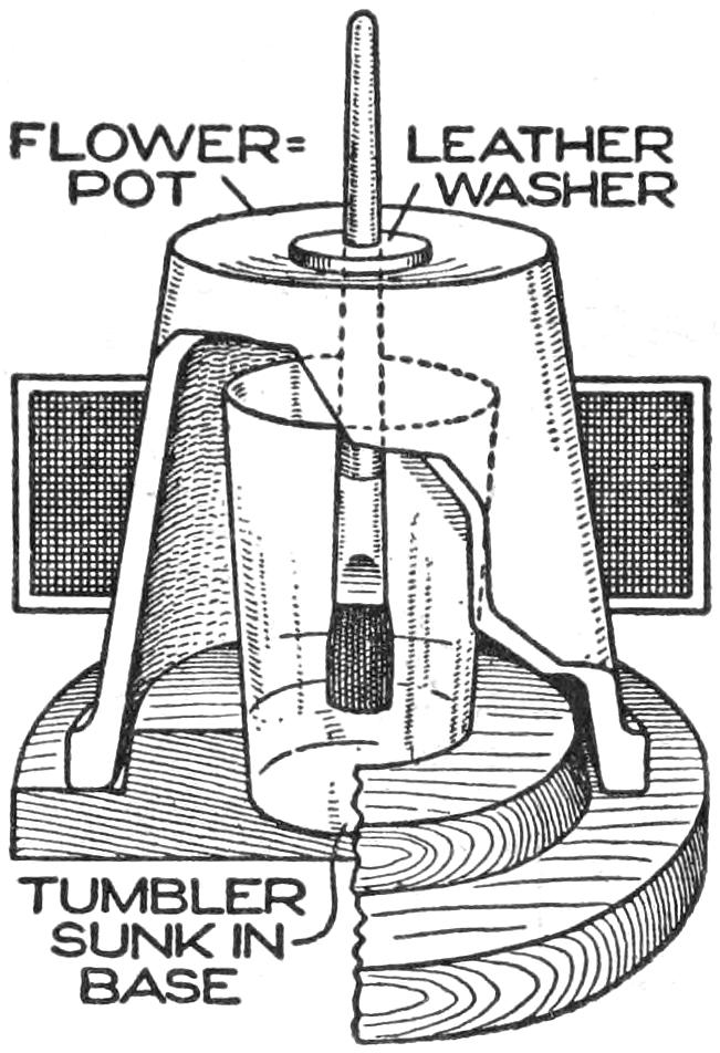
A simple, inexpensive, and practical pot and cover for holding shellac varnish in the pattern shop, or at home, is shown in the sketch. It consists of a base made of wood having in the center a counterbore into which a glass tumbler, or other container, is fitted. For the cover an ordinary flowerpot is used, fitting down over a ring on the base. An accumulation of shellac around the top cannot come in contact with the cover. The brush extends through the hole in the bottom of the flowerpot and is held suspended by means of a leather washer resting on it.—Contributed by J. D. Roberts, Kenosha, Wisconsin.
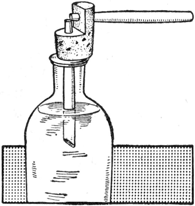
A simple vaporizer which can be used by designers to project their colors in a fluid spray, or by housekeepers to disinfect or perfume their apartments, can be made in the following manner: Two goose quills are forced through holes in a cork at right angles to each other, as shown. Place the vertical quill in a bottle containing the fluid to be sprayed and by blowing through the horizontal quill a very effective spray will be produced.—Contributed by Hazel Kolar, Maywood, Ill.
¶Old wringer clamps, used for holding the wringer to the tub, are very handy around a workbench.
Tooth powder is an excellent substitute for the powders which are sold for the purpose of preparing the glossy surface of tracing linen to receive ink. The gritty element removes the excess gloss which prevents the ink from taking hold. A second dusting with talcum powder makes a perfect surface for inking in.
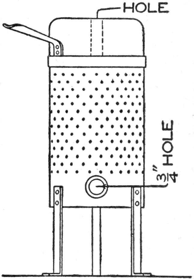
A small gas furnace for melting small quantities of gold, silver, or other metals, can be easily made as follows: Procure a cylinder of stovepipe iron of the desired size, say 4¹⁄₂ or 5 in. in diameter, and 6 in. long. Turn in the edge of one end so that it will hold loosely a disk of iron of the same thickness as the cylinder, to form the bottom. Punch ¹⁄₈-in. holes, about 1 in. apart, all over the cylinder and the bottom. This is to allow for the escape of moisture and air. Attach three legs to the sides with rivets, evenly spaced so as to raise the bottom 4 in. In the side of the cylinder cut a hole, 1¹⁄₄ in. in diameter, its center being 1¹⁄₂ in. from the bottom. Select a glass bottle whose diameter is 1 or 1¹⁄₂ in. less than that of the cylinder.
Make a putty of fire clay, and add about five per cent of plaster of Paris, and also add about a teaspoonful of vinegar, to prevent a too rapid setting. Place a mass of the putty in the bottom of the cylinder and press in the bottle after its surfaces have been well greased. The bottle should be well centered in the cylinder. Press the bottle well down, so that its bottom is on a level with the lower edge of the hole in the side. Fill in the putty to form the sides, tamping it[347] well all around the bottle, and build it up a little above the metal of the sides, carefully smoothing off the edge. With the fingers, or a spatula of some kind, cut out the putty in the hole to form an opening, ³⁄₄ in. in diameter. Allow the putty to set for more than an hour, and then with a circular, or twisting, motion remove the bottle. To prevent a vacuum in the bottom that will prevent removing the bottle easily, puncture the putty that lies on the disk with a hatpin, to allow the air to pass.
A few places will be found where the putty has not filled in properly, and these should be patched up while the filling is yet soft. The clay will probably shrink after standing for a time, and should be pressed out against the sides while in a plastic state. When dry, the furnace is ready for use.
In furnaces of this kind the jet of a large gas blowtorch is to be used. If a standard is rigged up to hold the blowtorch, it will be much easier for the operator. The jet from the pipe is thrown in the hole at the side and a crucible is placed in the furnace. It is well to make a cover similar to the body of the furnace with a hole in the center a little larger than the hole in the side.
A more efficient furnace can be made with two holes in the side, opposite each other, for using a double jet from blowtorches.—Contributed by James H. Beebee, Rochester, N. Y.
The hand, or pointer, is the only working part needed to perform the trick. A clockface can be drawn on any piece of white paper, and a pin stuck in its center on which the hand revolves. The hand A is cut from a piece of sheet brass, and may be in any form or design desired, but it must balance perfectly on the axle, which passes through a ¹⁄₄-in. hole in the center, or else the magic part will fail. The illustration shows a good design with dimensions that will cause it to balance well; however, this can be adjusted by removing some metal from the end that is heavier with a file or tinner’s snips, or a bit of solder may be stuck to the lighter end.
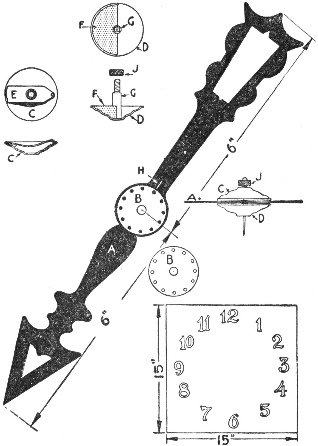
Design of a Hand That will Balance Well and the Parts for Its Axle
A disk, B, is cut from a piece of sheet brass, 1¹⁄₈ in. in diameter, twelve ³⁄₃₂-in. holes are drilled at equal distance apart near the edge, and a ¹⁄₄-in. hole is drilled in its center. This disk is soldered to the hand where both ¹⁄₄-in. holes will coincide. It is necessary to procure two washers, C and D, that are embossed, or raised, in the center, and about 1¹⁄₄ in. in diameter. These can be purchased from a dealer in curtain rods, the rod parts wanted being the washers used on the ends. A careful mechanic can raise the center portion of a brass disk by beating it over a hole with a ball-peen hammer.
One of the washers, C, has a spring, E, soldered at one end, and the other carries a small projection that will engage the holes in the disk, B. The[348] projection can be made by driving the metal out with a center punch, set on the opposite side.
The washer D is provided with a lead weight, F, and a ¹⁄₄-in. stud, G, is soldered in the center. The stud has a ¹⁄₁₆-in. hole drilled through its center for the pin axle. The weight is made by filling the washer with melted lead, which when cold is removed and sawn in two. One piece is then stuck in the washer with shellac. The stud is ⁷⁄₈ in. long with the upper part, about ¹⁄₄ in. in length, filed, or turned down, smaller, and threaded. Just below the thread, or on the shoulder, the body is filed square to fit a square hole filed in the face washer C carrying the spring. This square hole and stud end are necessary in order that both washers may turn together.
A Number is Mentioned and the Performer Gives the Washers a Twist to Set the Concealed Weight so That the Hand When Hung on the Dial will be Drawn to Point Out the Number Selected
The dial can be made of a piece of thick cardboard, or thin wood, with the numbers from 1 to 12 painted on, like a clockface. A pin, ¹⁄₁₆ in. in diameter, or an ordinary large pin, is run through the center so that it will project on the face side on which the hand is to revolve.
The washer D with the weight is placed on the rear side of the hand with the fixed stud run through the hole in the center of the hand; then the washer C is placed on the square part of the stud, and the nut J, which should have a round, knurled edge, is turned on the threads. This will cause the projection on the spring E to engage one of the small holes on the disk B. In turning the two washers, C and D, with the thumb and first finger of the right hand, the projection snapping into the holes of the disk B can be felt. The hand is placed on the pin of the clockface, and the washers are turned so that the weight will make it point to 12. Scratch a mark on the hand at H, also mark a line on the front washer at this point. These lines are necessary, as they enable the performer to know how many holes to snap the spring over to have the hand point at any desired number.
By reversing the hand it will point to a different number; for instance, if set for 8 and put on the pin backward, it will point to 4, and so on, with other settings. The dial can be held in the hand, hung on a stand, or fastened to a wall, and can be used to tell the day of the week, time of day, cards selected, etc. The audience can call for any number on the clockface, and the setting of the disks is an easy matter while holding the hand, or pointer, in the hands, so that it cannot be detected.
The use of steel wool in place of sandpaper when finishing off new or old work, when preparing it for varnishing or other finishes, will be found very helpful. It is put up in small packages and can be obtained in several grades of fineness. It is especially useful when removing old finishes, in and around moldings, etc., since it conforms[349] to irregular shapes as sandpaper will not. Put on a pair of heavy canvas gloves when using steel wool. They will keep the fine slivers out of the skin. These gloves will also be found useful when varnishing and painting.
To turn a long wood rod of small diameter is not an easy job for the amateur, and a suitable tool for the purpose is seldom found in the amateur’s outfit. The tool illustrated can be easily made from materials that are always at hand. A block of hard wood, A, is first provided, and a hole, B, large enough to admit the square strip from which the rod is to be turned, is bored in the end, whereupon the hole C, which has the diameter of the finished rod, is bored through the block. The hole D is next bored at right angles to the axis of the hole C, and so placed that its edge just touches the outer edge of the hole C. This hole is to receive an ordinary gouge, and must be of such size as to receive the gouge snugly.

A Block of Wood Fashioned to Hold an Ordinary Gouge for Turning Small Wood Rods
The gouge is ground back far enough on the under side to make the cutting edge level with its back, and then beveled off on the inside to a sharp edge. The gouge E is placed in the hole D with the cutting edge on the center line, as shown, and held in place with a wood plug, F. A little soap applied to the bore C will prevent binding.
To use the tool, a strip of wood is pointed sufficiently to allow it to enter the hole C a short distance. The strip may be rotated by holding it in the chuck of a lathe while the tool is held in the hand, using the handle of the gouge to prevent its turning with the stick.—Contributed by J. A. Brearley, Washington, D. C.

A handy ladder to swing from a hatchway can be made of a solid plank, as shown. Cut the plank to the length desired and saw notches on each side to form steps. With a solid hook to fasten it in a similar hook in the ceiling, at the edge of the opening, it makes a novel yet practical ladder.—Contributed by Victor Carpenter, South Bend, Ind.
An empty cartridge shell makes an excellent stopper for an oilcan in case the original stopper becomes lost. The cap in the shell is removed and the hole enlarged with the tang of a file so that a leather thong can be inserted. A knot is tied in the thong on both sides of the base, to prevent the thong from slipping either way. The end of the thong is tied to the bail of the can.
Make a thin solution of shellac in alcohol and add a teaspoonful of Venice turpentine to each half pint, and the same quantity of lampblack for a black enamel. Scrape the bare spots on the rod and heat it slightly, to melt the shellac for the first coat. Use a fine brush and apply two or three coats, which will give a smooth, glossy, and elastic surface that will not scale or crack.
[350]
When working with small, round articles, such as ball bearings, it often happens that they roll off the bench and are lost. To remedy this, I bored several holes, each 2 in. in diameter, in a convenient place in the workbench top, making them about ³⁄₈ in. deep, for the different articles. To make the small parts easily accessible the holes were filled in with thick paste made of plaster of Paris which was molded into a saucer shape. After the plaster became thoroughly dry the inner surface was painted over with white enamel. This made them easily cleaned with a damp cloth. Any article dropped into these depressions will roll to the center, and as the sides are curved it can be easily picked up when it is wanted.—Contributed by Frank L. Matter, Portland, Oregon.
The Molding Presents a Round Edge for a Pen and a Flat One for a Pencil
Picking up a smooth piece of ordinary wood molding, intending to use it as a ruler, I found that its shape, A, combined the properties of the round ruler and flat ruler, as well as assuming the third position D. A simple reverse changes the edge from a round to a sharp or flat, accommodating it to a pen or pencil, as shown. Such a piece of molding can be procured from a local lumber dealer.—Contributed by James M. Kane, Doylestown, Pa.
The Trousers can be Easily Hung on the Cross Bars to Keep the Crease in Them
A wood frame, similar to a picture frame, is made up and hinged to the inner side of the closet door with its outer edge hung on two chains. The inside of the frame is fitted with cross bars. After hanging the trousers on the cross bars the frame is swung up against the door where it is held with a hook. Several pairs of trousers can be hung on the frame, and when flat against the door it takes up very little space. The trousers are kept flat so that they will hold their crease.
If a person starts on a picnic with a ketchup bottle full of wood alcohol placed in the lunch basket and suddenly discovers that the alcohol stove was left at home, it is not necessary to walk back to get it; just unscrew the cover of the ketchup bottle and bunch a piece of cloth large enough to fill the top, soak it thoroughly in the alcohol and light it. The metal top is just the right size to make a hot flame.
¶A box 8¹⁄₄ in. square and 4 in. deep will hold one gallon.
[351]

To those interested in amateur theatricals the following method of showing dissolving views in the fire-light of pipe dreams and mind pictures will be appreciated.
A frame made of light material, A, Fig. 1, covered with red cloth and chalked to represent brick, is placed in the center of the stage. The central opening, representing the fireplace, must be rather large, about 12 ft. wide and 7 ft. high, because it is at the back of this opening that the pictures are produced. From the chimney back, 2¹⁄₂ ft. behind this opening, the sides, B, of the fireplace slope outward to the imitation brickwork. The walls of the fireplace are covered with sheet asbestos, for safety, and painted black; then ashes are rubbed on the chimney back and scattered over the hearthstone, to make the appearance more realistic.
The chimney back is removable, in fact it is one of a series of a half dozen screens, the others being behind it, the proper manipulation of which, together with changing lights, gives to the audience the effect of dissolving views of the dreams that are being acted out directly behind the screens.
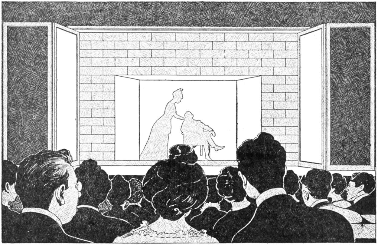
The Tableau is Played Out behind the Screens and is Dimly Seen through the Fireplace Opening When the Lights are Properly Controlled and the Screens Drawn Slowly
The screens are carried in a light frame, the top of which is shown in Fig. 2, with position of runs. The runs[352] are made of narrow strips of wood, fastened to the under side of two end pieces, for the screen frames to slide in. Corresponding strips are placed in a suitable position on the floor, to keep the screens steady in sliding. The frames holding the run pieces are longer than the chimney back is wide, and the upper one is placed as high as the brickwork, the shelf, or mantel, over the fireplace being an extension of the upper part, or frame. The screens are in pairs, as shown in Fig. 3, each one extending to the center of the fireplace. They consist of light frames covered with black mosquito netting. The upper and lower sides of the frames are sandpapered smooth so that they will move easily in the runs. The vertical sides of a pair of screen frames that meet in the center of the fireplace are made of one strand of wire, instead of wood, so that their motion will not be noticeable. To complete the apparatus, andirons and a gas log are needed in the fireplace, and whatever arrangements are necessary for the action of the views to be shown behind the screens.
If gas is available, an asbestos log is used in the fireplace, and it has a connecting pipe to the footlights, where four or five jets are located on the floor just back of the screens. A narrow board, painted black, is placed in front of the lights, which should be wide enough to conceal the lights from the spectators and reflect the light on the tableau. If the light is thrown above the imitation brickwork, then it should be made higher.
In most halls, and some houses, electric lights are used instead of gas, and in this case ordinary logs are piled in the fireplace on the andirons, and one or more red globes are introduced to produce the effect of glowing embers. The gas is more effective, however, because it is not easy to get a gradual rise and fall in the glow of electric lights. Four or five footlights are sufficient.
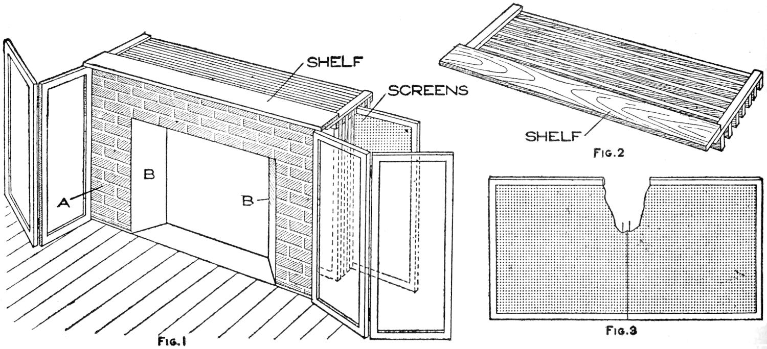
Fig. 2
Fig. 1
Fig. 3
Frames Made of Light Material and Covered with Black Mosquito Netting Serve as Screens Which are Operated in Runs Located behind the Fireplace That is Made Up in a Like Manner and Penciled to Represent Brick
The working of the dissolving views can be best explained by an illustration from “Reveries of a Bachelor.” The gas log is turned low to make the stage dimly lighted, and the tableau to be shown is all arranged behind the chimney back and the screens. There should be barely sufficient light to reveal the bachelor on the hearthstone smoking in the gloaming. Then the chimney back almost imperceptibly parts, that is, the screens of the first pair are gradually pulled apart, the footlights and gas log are gradually turned on, and the tableau behind the fireplace, being more brightly illuminated, is dimly seen through the series of screens. Slowly the successive pairs[353] of screens are drawn aside, and the tableau becomes quite distinct. Then the process is reversed, the screens are gradually replaced, the lights are lowered and the dream fades away; brightens and fades again; brightens and fades, till gone entirely. The screens are always slowly moving while the tableau is exposed, and this makes the illusory effect. It is evident that the success of this plan depends principally on the coördination with which the screens are operated. “Cinderella,” and many other tales based on the vagaries of the mind and having their source in glowing embers, can thus be presented.
Often the amateur turns out a very workmanlike piece of apparatus, which only lacks the addition of a scale or name plate to give it a truly professional appearance. I recently hit upon an excellent method of making these articles in a manner that will stand considerable wear and at the same time present a very good appearance. Simply take a piece of good Bristol board and letter it as desired with waterproof drawing ink, then apply a coat of clear varnish, such as is used on bird’s-eye maple furniture. After not less than 24 hours rub lightly with fine steel wool, wipe clean, and revarnish. Usually two coats are sufficient, and the last should be rubbed with a soft oily rag dipped in some abrasive material such as tooth powder, or one of the many powders used for metal polishing. Finally polish with a little oil, and the result will be a perfect imitation of celluloid.—Contributed by John D. Adams, Phoenix, Ariz.
Disappointment in the taking of pictures with a small camera is often caused by the inability of the photographer to obtain an accurate view of what he is photographing. If, instead of the small view finder on the camera, the device illustrated is used, a view of the resultant photograph may be obtained, right side up, and of nearly the same size as the finished print.
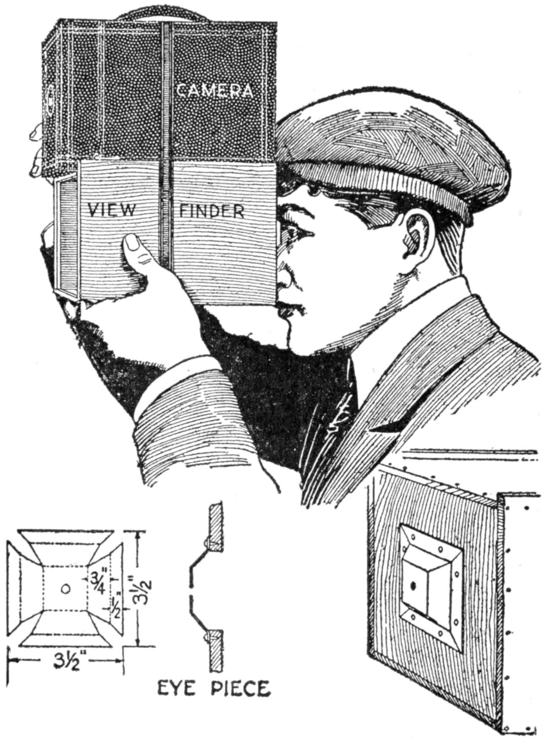
Sight through the Eyepiece for a Direct View of the Object Photographed, Thus Insuring More Nearly the Accuracy of the Result
The distance from the lens of the camera to the front surface of the plate or film must be determined. In the camera shown this was 4¹⁄₂ in. The distance from the small metal eyepiece, when it is in place on the box, to the inner side of the opposite end of the box must be made ¹⁄₂ in. shorter than this measurement. This will cause the box to be shorter than the camera.
The box is constructed so that the sides extend above the top and engage the camera. The view-finder eyepiece is made from a flat piece of sheet metal, laid out as shown, and bent into the desired shape. It is fixed over the center of the end of the box. The sight hole must be ¹⁄₃₂ in. in diameter. By sighting through the small opening in the eyepiece an unobstructed view of the prospective photograph is obtained.—Contributed by A. S. Thomas, Amherstburg, Ont.
[354]
It is often difficult to prevent a small rip in an inner tube of a tire from becoming longer, even though a patch has been applied. An effective remedy is to punch a small round hole at each end of the rip before applying the patch. This stops the tendency to rip farther when pressure is applied.—Contributed by George H. Holden, Chesterfield, England.
A simple and attractive protection for the wall back of the range or sink in a kitchen was provided by fixing a piece of plate glass to the wall by means of round-headed brass screws. The glass may be washed easily and can be removed when new wall covering is applied.—Contributed by Jennie E. McCoy, Philadelphia, Pa.
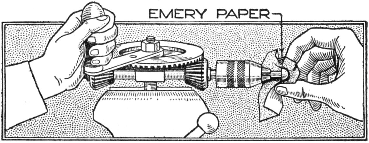
A Hand Drill Clamped in a Vise and Used to Polish Round-Head Screws
There are certain desired effects in polishing metal that can only be obtained with a true rotary motion. There is no amount of handwork that will produce a proper finish on the round head of a brass screw. Therefore, when small pieces of metal are to be shaped up with the file and polished, simply set them in a three-jaw chuck of a hand drill, and then clamp the drill in a vise, as shown in the illustration. Operate the drill with the left hand and hold the file, or emery paper, with the right, and a finish will be obtained that can in nowise be distinguished from lathe work. It is surprising how different round-head brass screws appear when treated in this manner.
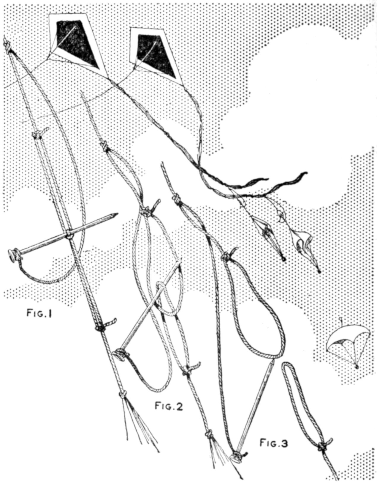
Pull In About a Yard of the Kite String and Release It, Tripping the Parachute
Parachutes may be released from suspended kites readily by providing tripping loops on the kite tail, as shown in the illustration. Form a loop on one end of a piece of cord, and tie the other end to the kite tail. Make a loop in one end of another piece of cord and tie the other end to the top of the parachute. Tie a piece of cord around a nail close to its head and fix this also to the kite tail. Pass one loop through the other and insert the nail, as shown in the sketch. To trip the parachute, pull in about a yard of string and release it quickly. The parachute will trip without fail. The end of the string may be fastened to a stake driven into the ground or it may be held in the hand.
An ordinary blotter may be transformed easily so that it will remove ink completely when applied instead of leaving sufficient to recognize the script, by steeping it in a solution of oxalic acid. Permit it to dry after several applications of the acid. It will be the source of much amusement, and is useful as well.
[355]

Clever and baffling though it may be, the magic-candle trick may be performed easily and with professional skill by a person who has made a few simple preparations. The illustration shows the candles arranged on a table made of a music stand.
Candles, cigars, or pencils may be used, but for the purpose of this description the former will be used. The candles are of different colors but of the same size and weight. The manipulation is as follows:
Exhibit a tube of brass, cardboard, or other suitable material, just large enough to contain a candle. Then retire from the room, leaving the tube on the table while one of the spectators selects one of the candles and places it into the tube, covering the end of the latter securely with a small cap. The other candles are hidden before the performer is permitted to return. The trick is to announce the color of the candle contained in the box by merely passing the hand over it several times. The box and candle are passed out for inspection and will bear it if properly prepared.
The secret of the trick is this: The first candle, for example, the white one, is unprepared. The second, a blue one, has concealed in it, ¹⁄₂ in. from the top, a small piece of magnetized steel. The third candle, a red one, has a similar bar concealed at the middle; the fourth, a magnetized bar ¹⁄₂ in. from the bottom, and the fifth candle has the bar at a point halfway between the middle and the bottom. The candles are made of wood and the magnets may readily be imbedded in them. They are made of two pieces glued together like a pencil.
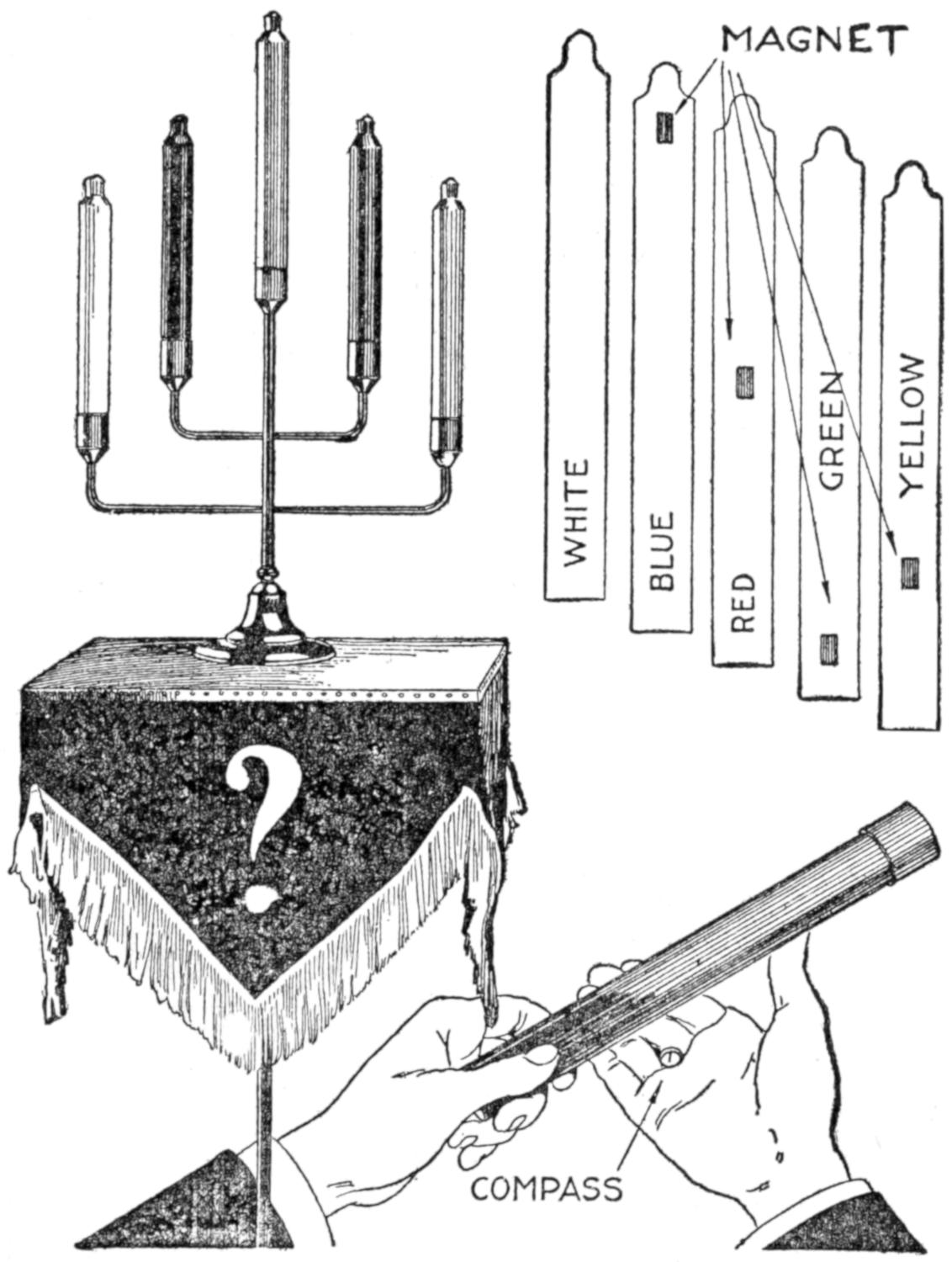
Mysterious Passes over the Concealed Candle are Made and Its Color Announced
The performer hides a small compass in his palm. It is held in place by a wire clip, gripped between the second and third fingers near the knuckles. A wave of the hand over the tube containing a candle will affect the compass if any candle other than the white one is used. Its needle will vibrate when approaching the concealed magnet, and by determining quickly the position of the magnet, the color may be announced.
Those who offer guesses usually insist that some electrical device is used.
[356]
Placing a lock lid in the top of a desk drawer provided a writing board and also gave privacy to the drawer, as shown in the sketch.
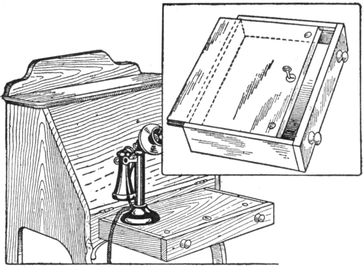
The Lid Provides a Writing Slide and Gives Privacy to the Drawer
A lady’s desk in a nicely furnished room was used for the telephone and as the desk was often locked there was no place on which to rest the instrument or to take notes. The drawer lid, locked with a chest lock, proved effective. The lid may be moved back so as to expose the contents of the drawer. It was finished to match the desk.—Contributed by Victor Labadie, Dallas, Tex.
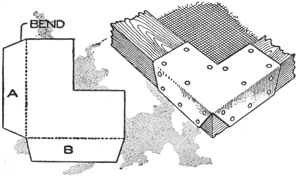
Sheet-Metal Braces Used on a Loose Window-Screen Frame to Make It Rigid
An old broken fly-screen frame was made quite rigid with the use of metal braces, cut as shown and fastened with nails to each corner. The brace was cut from sheet metal, and the edges A and B were cut and bent at right angles to the main part, with their extreme edges bent over the frame. These were sufficient to make the frame as rigid as a new one.
The temperature of a room may apparently be raised several degrees with the same expenditure of heat, and greater comfort will result by the application of a simple principle. In summer a moist day seems warmer than a dry one though the thermometer registers the same. By permitting steam to escape from a radiator or keeping a kettle boiling on the stove, the air is moistened and feels warmer.
The water heater illustrated is for use on a 110-volt circuit without added resistance. It consists of two electrodes which are immersed directly in the water; and while it is not as artistic as the usual nickelplated heater, it is usually more economical and has the distinct advantage that it cannot be burnt out. It may be made as rapid in action as desired, is inexpensive and very convenient where water is required for experimental or industrial purposes.
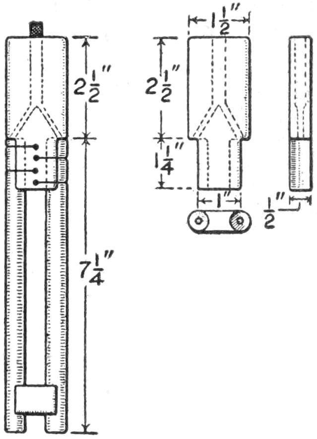
For the electrodes, procure two ¹⁄₂-in. uncoppered carbons, and drill a hole in the top of each of these so that feed wires can be attached. The handle is shaped from a piece of hard wood. The lower end is hollowed out half round at either side, so that the carbons will fit in snugly. Four small holes are then drilled through from side to side for binding wires, and a large hole is made in the center for the feed wires. Two smaller branch holes are then drilled to join the center hole, so that the double feed cord may be branched out to reach both electrodes. The outer edge of the handle is neatly rounded off and boiled in paraffin so as to render it impervious to moisture.
Remove sufficient insulation from the feed cord to make a good connection[357] with the carbons. Fish the wire through the handle from the upper end. Pull each of the two ends pretty well through, so that they can be securely threaded into the holes previously made in the carbons. Have the latter quite hot and run in as much solder as possible, forcing it in with the end of a match as it becomes plastic. Remove all traces of the flux, and paint the connection with some melted pitch, taken from the top of a discarded dry cell. The feed cord may then be pulled up tightly, which will draw the carbons in place. They are then bound by threading through several strands of copper wire. If the holes in the wood are slightly countersunk, and two small grooves filed around each carbon at the right places to let the holding wires in, the binding feature may be disposed of very neatly.
In some localities the water is so free from all mineral salts that it will not carry the current freely, which means that the electrodes must be placed closer together, or else a small pinch of common salt may be added to the water. Although, in sterilizing instruments, boiling eggs, or something of that sort, this would be of no advantage, the salt greatly hastens the boiling.
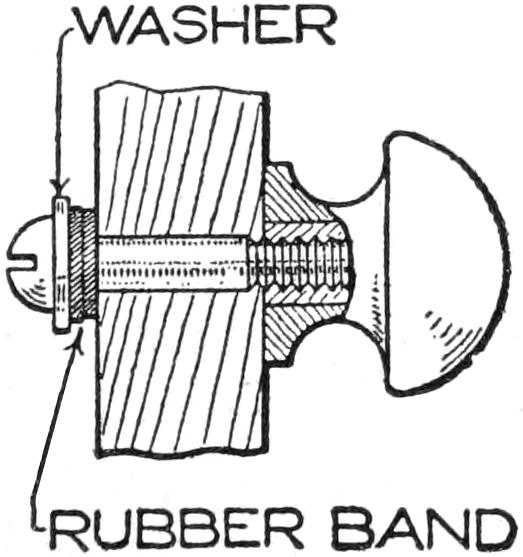
Drawer handles frequently become loosened and sometimes cause further annoyance by falling to the floor or becoming lost, because the bolt fastening, as shown in the sketch, is not secure. This may be avoided by inserting a rubber band between the head of the bolt and the drawer front. When the knob is drawn up tightly the pressure of the rubber band prevents it from becoming loosened.—Contributed by O. F. Germaine, Akron, Ohio.
The modification of the well-known mechanical dancer shown in the illustration is based on the principle of the electric bell. While the amusing antics of the mechanical dancer are controlled by the hand, the manikin shown is actuated by the electromagnet.
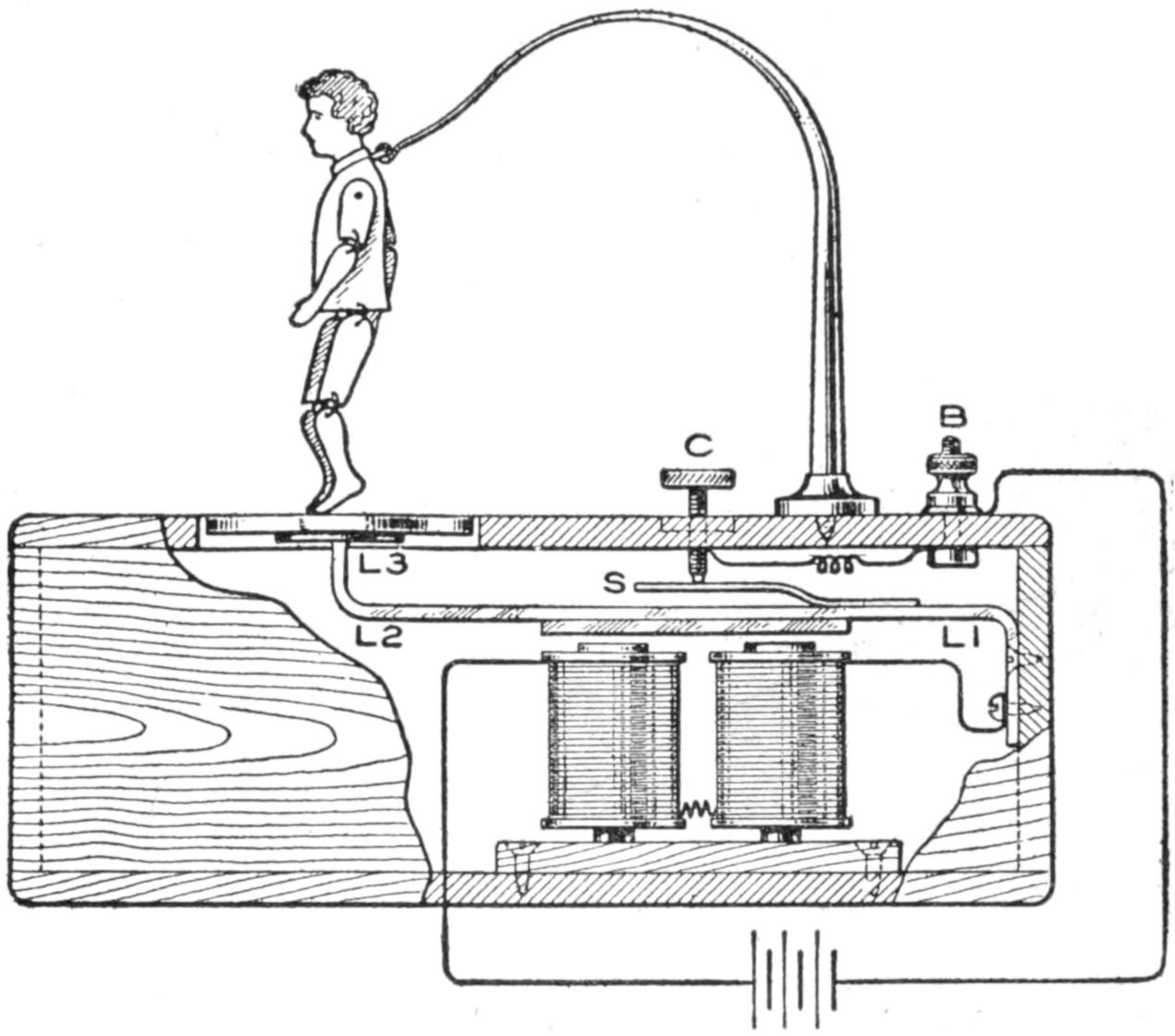
When the Contact is Made the Figure Dances
The mechanism is contained in a box. It consists of an electromagnet with a soft-iron armature carried by a spring. A wire from the battery goes to the magnet. The other terminal of the magnet connects with the armature spring at L1. The spring is bent at a right angle at its other end, L2, and carries a platform, L3, strengthened by a smaller disk underneath. The dancer performs upon this platform.
A contact spring, S, is carried by the armature spring. A contact screw, C, is adjustable in its contact with the spring S. A wire runs from the contact screw to the binding post B, to which the other battery wire is connected.
The current keeps the platform in constant vibration, causing the dancer to “dance.” By means of the screw C, the action of the current may be varied, and the “dancing” will vary correspondingly.
The figure is made of wood with very loose joints and is suspended so that the feet barely touch the platform.—Contributed by Edward C. Connelly, Wilkesbarre, Pa.
[358]
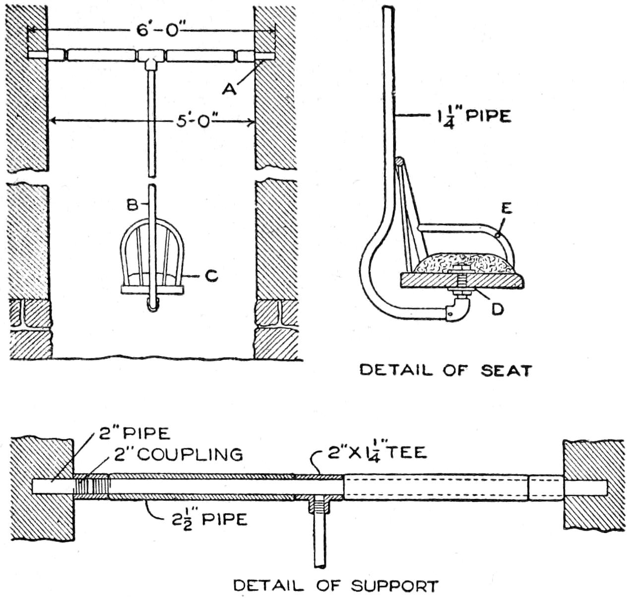
This Substantial Swing Guards the Youngsters from Injury by Brushing against the Brick Walls
A narrow space between two city houses was used to erect a swing, as detailed in the illustration. A piece of 2-in. iron pipe, A, was cut 1 ft. longer than the space between the walls. Two pieces of 2¹⁄₂-in. pipe and a 2¹⁄₂ by 2¹⁄₂ by 1¹⁄₄-in. tee, as shown in the detail, was slipped over the 2-in. pipe, which was built into the walls. A 1¹⁄₄-in. pipe, B, 20 ft. long, bent as shown, was joined to the tee, and a seat, C, was attached. The construction of the seat is shown in detail, being fixed to the wooden part with washers, nuts, and a threaded nipple, D. A cushion and a removable safety bar, E, were also features. This swing is safer than one of rope, and will stand much greater wear.—James N. Reed, San Francisco, Calif.
Four wooden door bumpers, of the rubber-tipped knob type, fastened to the lower ends of the legs of one of the kitchen chairs, make an almost indispensable high chair, which will bring the table work to a more comfortable height than the ordinary chair does. The young child also will appreciate such a chair at the dining table. When it is no longer needed, the knobs can be unscrewed quickly.—J. E. McCoy, Philadelphia, Pa.
The one-string banjo, the cigar-box guitar, and similar vaudeville favorites are giving way to the tantalizing ukulele, and the home mechanic, to be up to date in his musical craftsmanship, must fall in line. The size of this instrument makes it especially suited to the cigar-box type of body construction, as detailed in the several sketches and shown in the photograph reproduced. This neat ukulele was made at a cost of 30 cents, by careful selection of materials from the shop scrap stock.
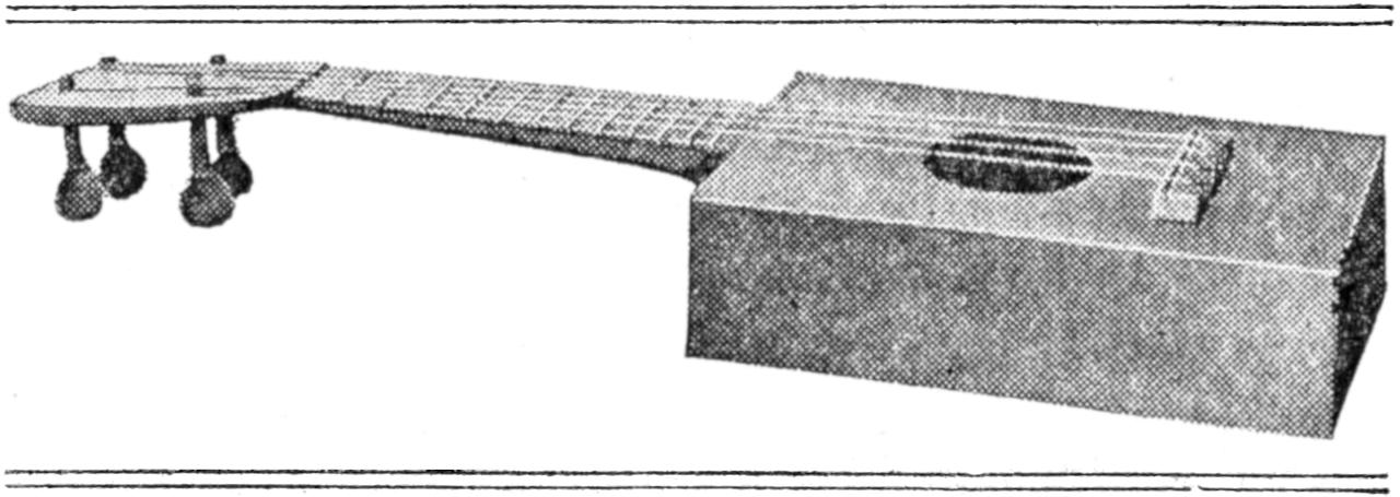
This Cigar-Box Ukulele Cost the Maker 80 Cents, and Affords Him the Pleasures of a More Expensive One
A cigar box of good-quality Spanish cedar, about 2¹⁄₂ by 6 by 9 in., as shown in Fig. 1, is used for the body. Remove the paper carefully, so as not to mar the surface, soaking it if necessary. Take it apart, and if the nail holes are too numerous, or broken out, trim off the edges. Fit the parts of the body together, as shown in Fig. 2, the top and bottom pieces resting against the side and end pieces, and the latter between the sides. Cut the 2¹⁄₂-in. hole in the top piece, as shown, 3³⁄₄ in. from the neck end. To reinforce the body make strips A, ¹⁄₄ in. square, and fit them to be glued into the corners at the top and bottom. Make strips B,[359] ¹⁄₄ by ⁵⁄₈ by 4¹⁄₂ in., and glue them under the top and on the bottom as indicated in Fig. 2. The final assembling and gluing of these parts, using animal glue, should be done after the bridge C is in place, and the other parts are made. The bridge is of hard wood hollowed underneath the notched edge, as detailed, and is fitted with a metal string contact.
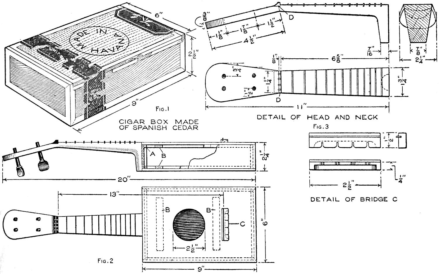
Fig. 1 Fig. 3
Fig. 2
To Keep in the Fashion in His Musical Craftsmanship, the Home Mechanic may Make a Cigar-Box Ukulele as Detailed
Spanish cedar or mahogany is suitable for the neck, detailed in Fig. 3. A single piece is best, but the extension for the pegs and the wider end at the body may be joined and glued to the main portion of the neck. Dowels should then be used to reinforce the joints. The outline of the parts of the neck are shown in detail in Fig. 3. In the sectional view at the right, the shape of the neck at the thinnest and thickest parts is shown by the two upper curved, dotted lines. The nut D is made of mahogany, walnut, or other hard wood, the grain extending lengthwise, and the notches for the strings spaced as shown.
The making and spacing of the frets must be done very carefully. They are of aluminum, brass and other metals being suitable also. Make the frets ¹⁄₁₆ by ³⁄₁₆ in. and cut grooves ¹⁄₈ in. deep for them. The spacing of the frets is determined as follows, a standard practice: The distance from the metal string-contact on the bridge to the nut should be measured carefully. The first fret, near the head, is ¹⁄₁₈ of this distance from the nut, the total length being in this instance, 13 in. The second fret is set ¹⁄₁₈ the distance from the first fret to the bridge; the third, ¹⁄₁₈ from the second fret to the bridge, etc. The frets must fit tightly in the grooves, requiring no special fastening. The tuning pegs may be bought or made.
In assembling the parts, fasten the end of the body to the neck, with glue, reinforced by screws. Set its upper edge parallel with the fingerboard, and so that the latter is flush with the top of the body, when fitted to it. Assemble the body, without the top, gluing it to the end, fixed to the neck. When this portion is thoroughly dried, fit the top into place finally, and glue it. The whole construction is then cleaned, sandpapered, stained, and shellacked or varnished. The stringing of the instrument is simple, and the strings may be purchased in sets.
[360]
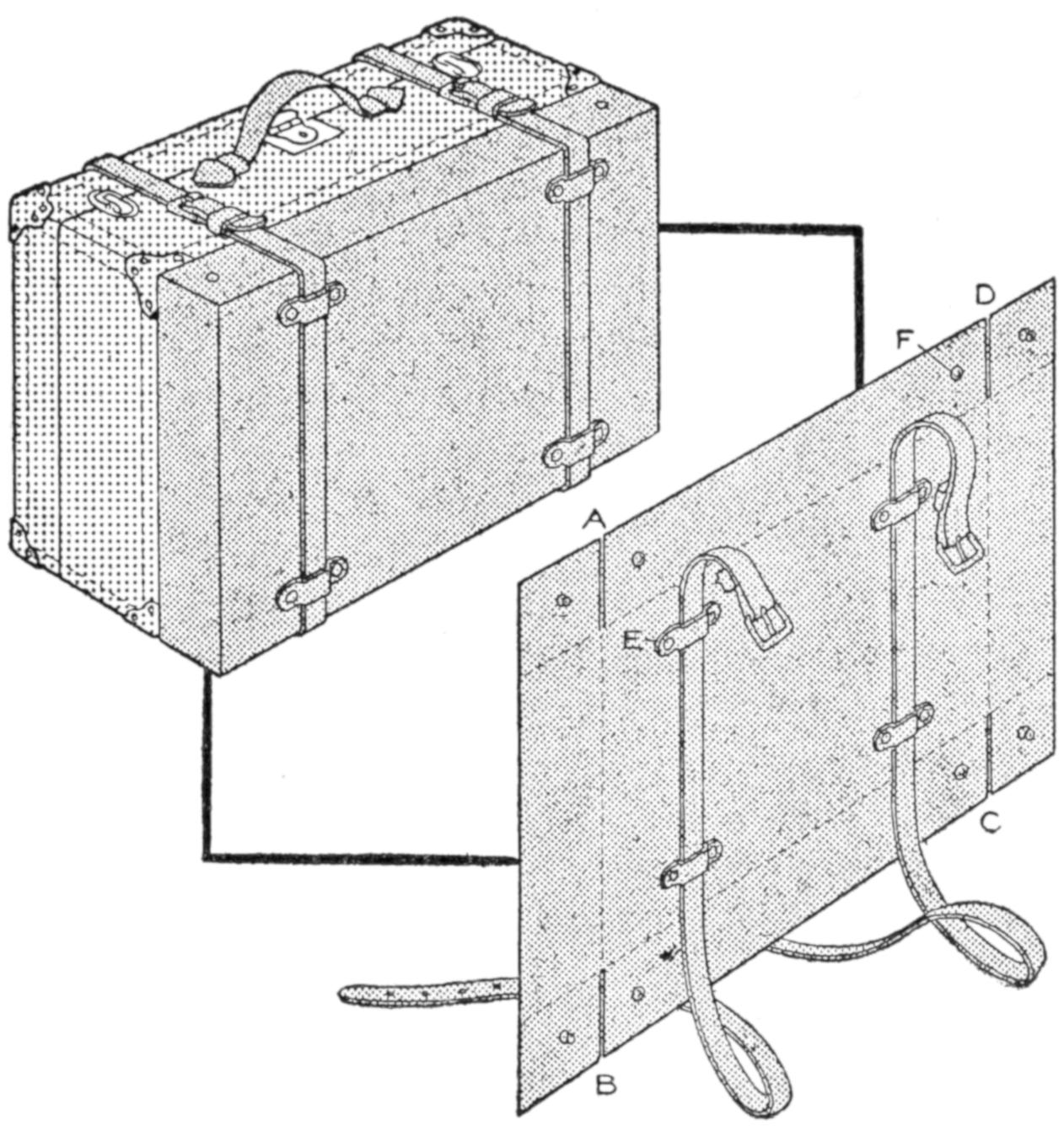
A handy addition to the traveler’s equipment is a suitcase extension that may be removed when not in use, and folded compactly, inside of the suitcase if desired. This latter feature is provided for by arranging the extension to be folded vertically at the middle. Heavy leather, cloth board covered with strong linen, or canvas of a suitable color may be used. If cloth board is used it should be cut the size of the side of the suitcase, and smaller sections hinged to it at the folds. The leather need not be reinforced if it is fairly strong. Cut the leather at A, B, C, and D, and arrange it to be folded on the dotted lines. Rivet guides for the straps, as at E. Fit the corners with buttons or snaps F, which are locked in position when the extension is in use. The device slides over the suitcase and may be drawn tightly against it when empty.—R. S. Matzen, Fort Collins, Colo.
Attempts to make “close-up” photographs of machinery, or highly polished objects, often fail because the reflection of light upon the bright surfaces causes a blur in the photograph. Some photographers use putty to deaden the gloss. A lump of putty is rubbed over the surface gently where a brilliant reflection is visible, or the entire surface is rubbed so that it presents an even, dead finish on the ground glass of the camera, when focusing.—Ralph W. Tillotson, Erie, Pennsylvania.
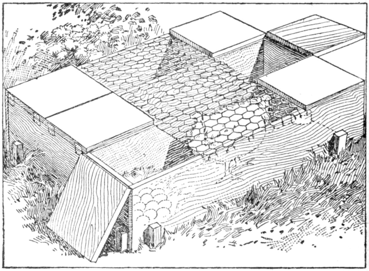
Each Hen Has a Compartment, with Plenty of Space for Exercising
When several hens are to hatch out settings at the same time, considerable space can be saved and much convenience afforded by making a coop as shown in the illustration. It consists of an outer frame of boards, 1 ft. wide and 6 ft. long, or as long as desired for the runway. The frame is divided into compartments by boards extending from end to end, each compartment being for one hen. The frame is placed on level ground and staked in place. At opposite ends of each compartment is a hinged cover. The intervening space is covered with wire netting, with shelter boards placed loosely over it. Under one of the hinged covers the nest should be placed on the ground, and at the opposite end food and water are provided. Each hen has plenty of space to exercise in, and must at least get up for food and water. The individual covers permit separate examination of the eggs, or feeding of the hens.—F. W. Buerstatte, Pullman, Wash.
[361]
While sitting in a room around a lamp, a group of workmen discussed the probable causes for the smoking of an oil lamp. By way of experiment, holes were punched in the perforated part of the burner, increasing the draft through the glass chimney. It was then possible to turn the light up much higher, without the usual deposit of smoke. As a result of this, several other troublesome lamps were soon remedied.—J. E. McCormack, Haliburton, Ontario, Can.
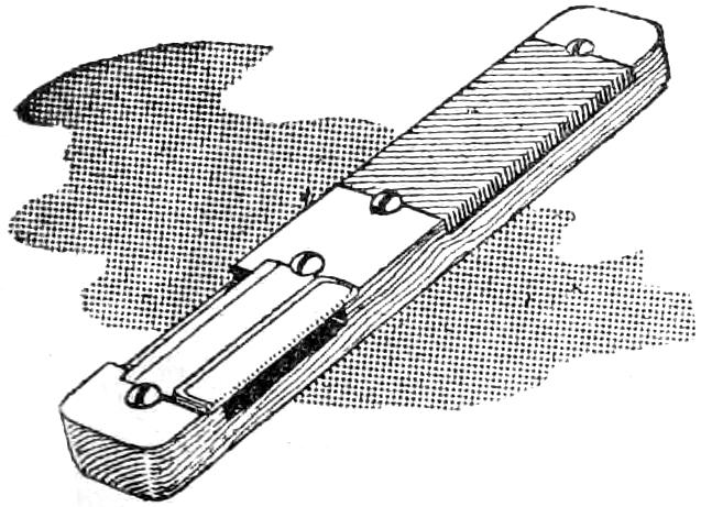
This tool combines a knife and a file in one handle, of wood, 7 in. long. The knife is a single-edged safety-razor blade, clamped to the handle by two round-head screws. A space, ¹⁄₈ in. deep, under the blade is allowed for chips, and a piece of a fine file is recessed into the other end of the handle. To use this sharpener, hold it as a pocketknife is ordinarily held in whittling. The blade will keep its edge for a considerable time.—Ralph W. Hills, Madison, Wisconsin.
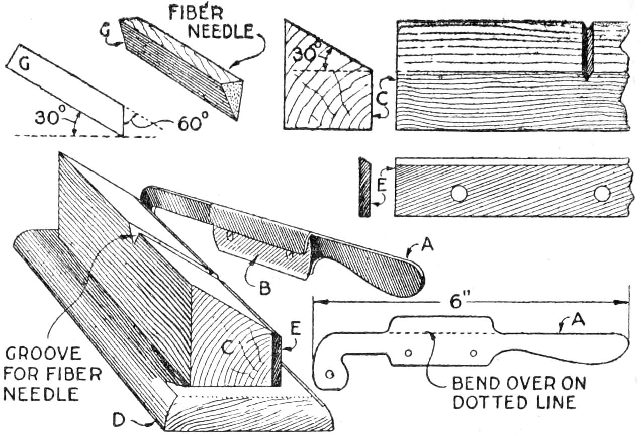
By Using This Needle-Sharpening Device the Life of Records is Prolonged
A practical sharpener for fiber phonograph needles may be made as follows: A lever handle, A, is cut from heavy sheet metal. A safety-razor blade, B, is bolted to it, and the metal flap bent over as indicated. A block, C, is cut so that the upper face makes an angle of 30° with the base, is faced with a metal strip, E. A triangular groove is cut or filed for the needle G. The lever is hinged, as shown, by means of a screw. A base, D, may be added. To operate the sharpener, place a needle in the groove so that a very small portion of the playing end extends past the face of E, and shear off the end.—C. M. Hall, St. Louis, Missouri.
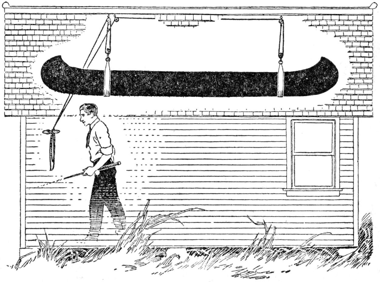
The Canoe is Stored in the Garage, and Conveniently Hoisted into the Gable
A canoe, or small boat, which is taken from the water when not in use, suffers damage if it is left unprotected in the open. A practical method of storing it so that it can be taken out quickly is to suspend it from the roof structure of a small shed, or a garage, by means of slings. The latter are made of double thicknesses of strong canvas, and are provided with rings where they join to the lower pulleys of the hoisting rope and tackle. The cushions, paddles, etc., may be left in the canoe.—Robert W. Jamison, Mitchell, S. D.
[362]
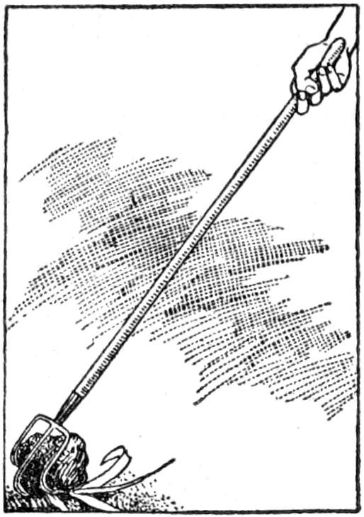
Small corn is often injured by lumps of dirt being thrown on it when cultivating. If these are not removed the corn may grow to one side or may lie flat on the ground. In order that I need not get off the cultivator to remove such lumps, I made a rake out of an old fork. The tines were heated and bent, as shown. An iron rod may be used for the handle, but the wooden one is light and easy to hold.
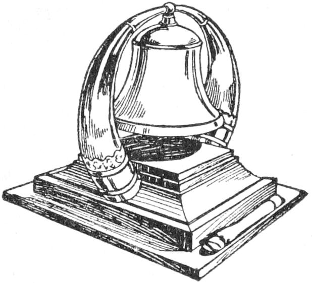
Two highly polished horns fitted into a polished wooden base and banded with silver form the support for a call bell shown in the illustration. A tapper, which rests beside the stand, was made of a deer hoof.—James M. Kane, Doylestown, Pa.
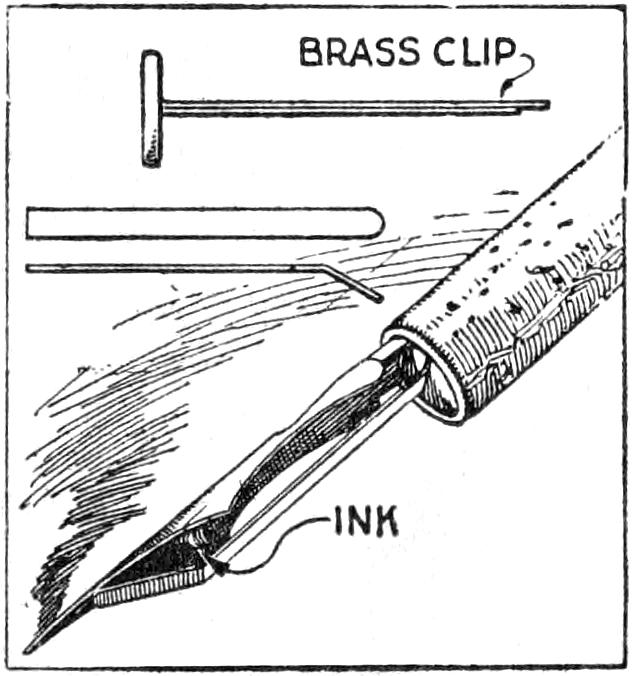
An ordinary penholder and pen point may be easily converted into a fountain pen, with the aid of a brass paper clip of the kind shown. The cap is pried off and the prongs straightened. One of the prongs is cut to suitable length, and the end bent as indicated. It is then inserted in the penholder, and adjusted to ¹⁄₈ in. from the end of the pen point. The ink is placed between the bent clip and pen point, from where it feeds evenly as needed. This kink is helpful when using the heavier drawing inks, as well as with writing inks.—R. L. Templin, Champaign, Ill.
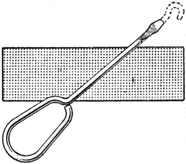
Losing a sewing-machine screwdriver, I easily made another by cutting off the hook end of a buttonhook with a chisel. The cut end was placed upon a piece of iron and, with a hammer, formed into a screwdriver in a few minutes. The rounded top of the buttonhook makes it convenient to handle or hang up.—E. M Bierwagen, South Bend, Ind.
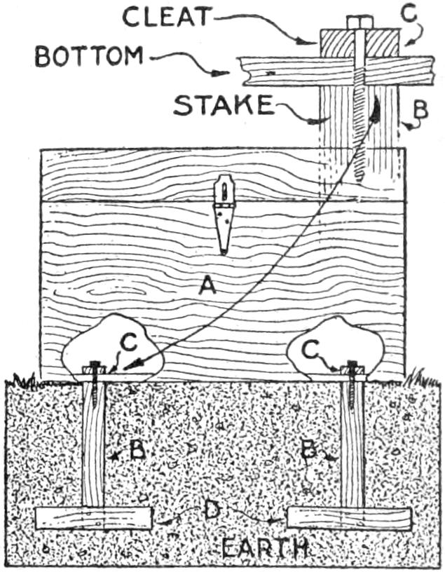
Unless a camp chest is secured to the ground so that it is difficult for marauders to carry it away it cannot be left at unguarded camps without some danger of theft. By fitting the chest, A over stakes, B set into the ground with crosspieces, D a secure fastening is provided. Cleats, C, with holes for lag screws, are fitted into the bottom of the chest, making it easy to remove the fastening when desired. The cleats are kept in the bottom of the chest when not in use.—K. A. Thompson, Lexington, Va.
¶By carefully piercing the small end of an eggshell with a large needle, a funnel for filling very small bottles is provided.
[363]
This toy, amusing for the youngsters, and their elders as well, will repay one for the making of it. Use a cigar box for the carriage, making it about 10 in. high, and shape it in the design shown. Nail a piece of wood, ¹⁄₈ by 2 by 4 in. wide, on each side of the carriage, and drill ¹⁄₈-in. holes in them for the axle. For the horse, take a piece of wood, ¹⁄₂ by 4 by 6 in. long, and draw an outline of the head, neck, and body. Cut this out and drill ¹⁄₈-in. holes where the legs are attached.
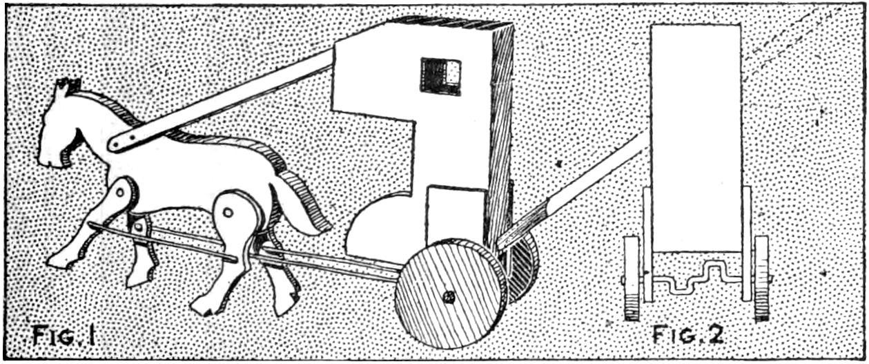
The Toy is Pushed by Means of the Handle, Causing the Horse to Walk
Cut the legs as shown, about 3¹⁄₂ in. long. Attach them with small bolts, or rivets, allowing space to move freely. The wheels are made of pine, ¹⁄₂ in. thick and 3 in. in diameter. The axle is made of ³⁄₁₆-in. wire bent to the shape indicated, ¹⁄₂ in. at each offset. Fit the wheels on the axle tightly, so as not to turn on it, the axle turning in the pieces nailed to the sides of the carriage. The horse is attached to the top of the carriage by a strip of wood. A 3-ft. wooden handle is attached to the back of carriage to guide it. Wires are attached to the legs, connecting with the offsets in the axle.—Charles Claude Wagner, Los Angeles, Calif.
The gummed flaps on envelopes for first-class mail are generally short, and for sending photographs or second-class matter these short flaps do not stay tucked in. The solution is to lengthen the flap, by pasting on a sheet of paper, using the gum thereon.—G. N. Neary, New York, N. Y.
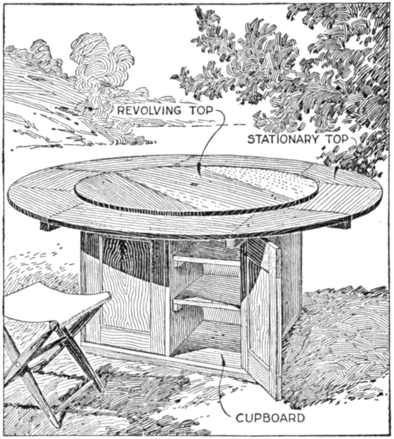
The Persons Seated around the Table Help Themselves to the Food Conveniently by Turning the Central Top
Picnic parties on one of the Maine lakes make much use of a large table, having a revolving top, so that the lunch may be placed on the center portion and the persons seated around the board may help themselves handily. The stationary top is supported on several cross braces of 2 by 4 in. stuff, and the revolving top, pivoted at the center, is carried on wooden roller bearings, fixed near its circumference. The lower portion of the table is in the form of cupboards which are padlocked, providing storage space for equipment left for the use of picnickers. The table is set under a pergola, which provides shade. Benches, curved to fit the table, may be used conveniently with it. A small table of this type is practical as a children’s play table, providing convenient storage space for toys and other articles.—E. E. Dickson, Holyoke, Mass.
¶When, in papering a bathroom with the same tiled paper on sides and ceiling, the paper does not match in the ceiling corners, place a strip of quarter-round there, and color it to suit the paper.
[364]
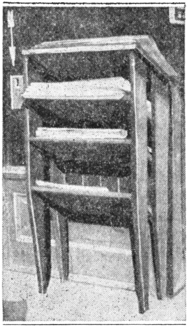
A silent, yet very successful “newsboy” is shown in the photograph reproduced. Each rack holds one of the daily newspapers. The passer-by puts a penny in the slot and selects his paper. The penny falls down a chute, striking a bell, as evidence that the customer has paid. Hundreds of papers are sold from this rack each day without the aid of the newsboy’s shouts. The slanting shelves make it unnecessary to provide weights for the papers.—M. F. Hall, St. Louis, Mo.
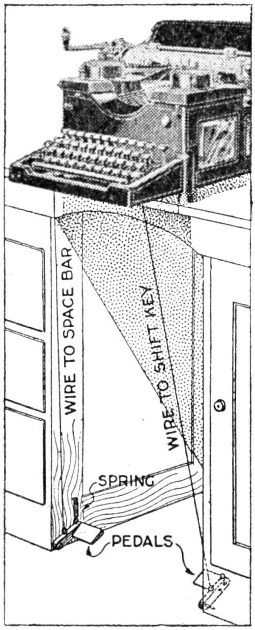
By attaching pedals to the space key and shift key I increased my typewriting speed about 20 words a minute. I made two pedals fast to the typewriter desk, as shown, then ran stiff steel wires up to the keys, connecting the latter to the wire with rubber bands. The pedals are adjusted so that a light tap operates them. If a light typewriter is used, it should be fixed to the desk. The wires can be unhooked quickly from the typewriter, and suspended on hooks under the edge of the desk.—W. J. M., Manila, P. I.
Working in a photo-print finishing plant where often several jobs need attention and accurate timing, all at the same time, I find a pointer on my watch crystal a great help. The crystal was loose enough to permit turning it. I glued a three-cornered piece of black paper to the under side of the crystal at the edge. When a batch of prints is placed in a bath, the pointer is set 15 minutes ahead of the minute hand. When the latter reaches the pointer, it reminds me to remove the prints. After placing a batch of films in the developing tank, I set the pointer ahead of the minute hand the required time for developing, placing the watch in view, to see readily when the time is up.—A. J. Viken, Waterloo, Iowa.
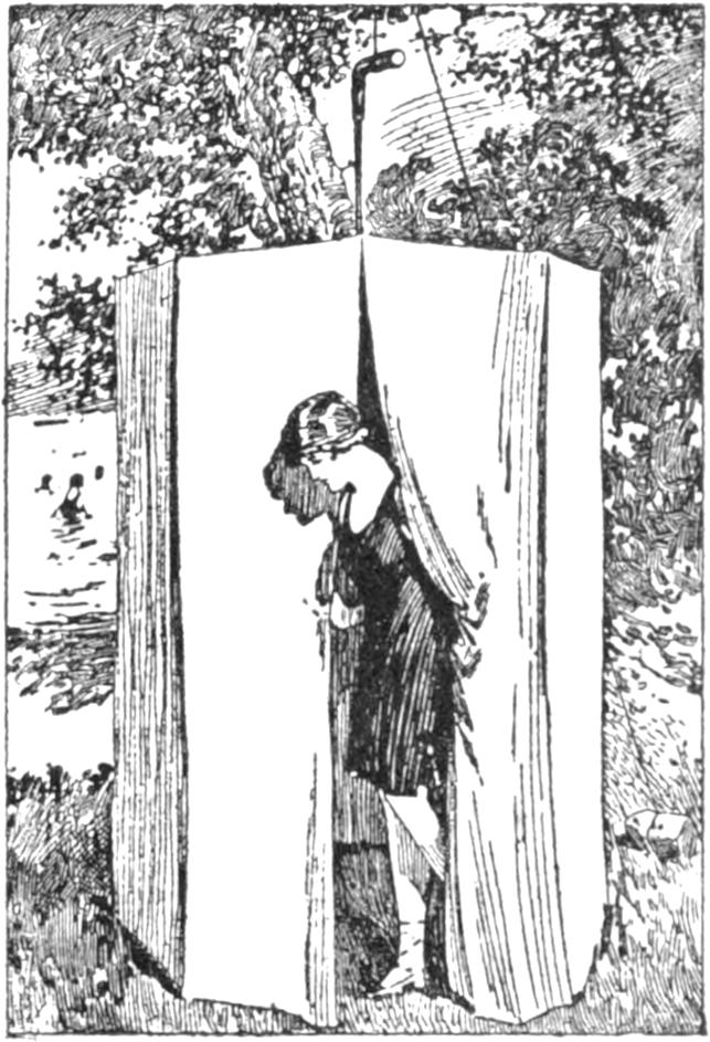
Picnickers desiring to go in bathing are often handicapped by the lack of a convenient place to change clothes. An umbrella and some paper muslin provides a light portable tent that is practical and inexpensive for such uses. Cut the dark paper muslin into as many 9-ft. lengths as there are sections of the umbrella. Sew these strips together. At each seam tie a string about a yard long and a stout cord 15 ft. long to the handle to hold up the tent. For use, open the umbrella, invert it, and to each rib tie one of the strings. Then tie one end of the cord to the handle of the umbrella and suspend it from a tree or other support as shown, weighting or tying down the other end.—Mabel Hubbard Birch, Cincinnati, Ohio.
[365]
Persons who occasionally take an outing or go camping will find a written list of articles needed on the trip a great saving of time and mental energy. This list should be made while making preparations, and again read shortly before the departure. It may be kept from year to year, and items added or withdrawn, as experience teaches. Classification is desirable, under heads such as camping gear, cooking utensils, tableware, foods, supplies, etc. Each member of a party can agree to furnish certain articles, avoiding duplication. Anyone who has gone on outings and left behind some much-needed article, will readily realize the help such a list can be, and by its use the amateur may profit from the experience of others.
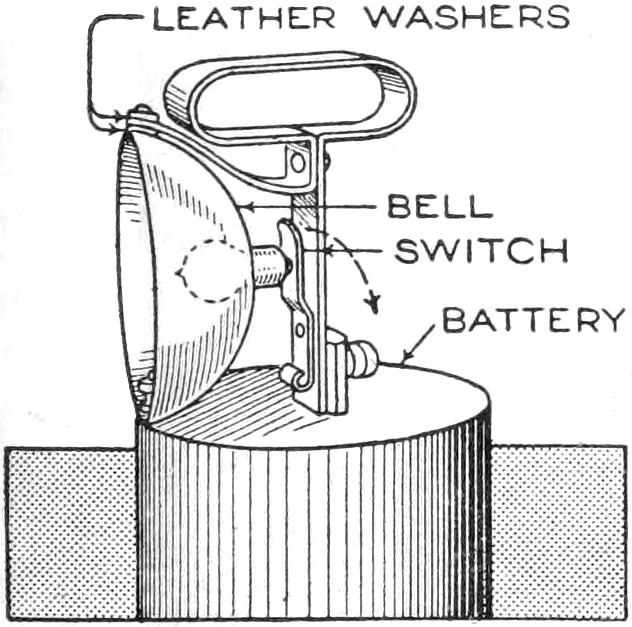
By attaching a handle for carrying, and making suitable connections, a portable trouble light was made of a dry battery. A strip of iron was bent to the shape shown, for the handle, and fixed to the binding post on the carbon. A bell from an alarm clock was drilled and tapped to fit a small light bulb, and fastened at the zinc post. The upper edge of the bell was bolted to the extension of the handle, as shown, leather washers insulating it. A small switch, riveted loosely to the iron strip, controls the light.—Carl A. Haberlein, McPherson, Kan.
¶Books to be stacked or carried should be arranged with the backs on alternate sides.
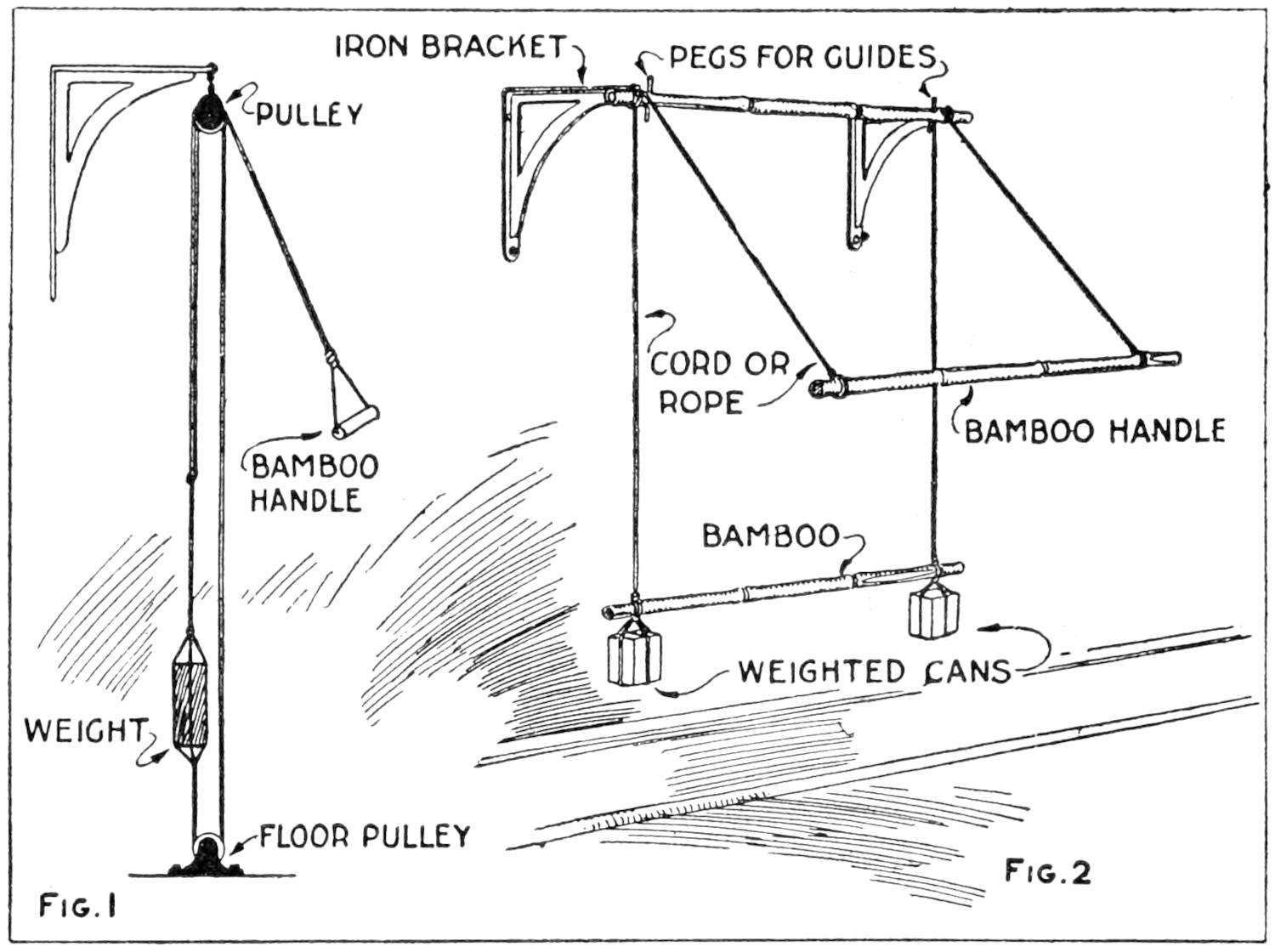
Fig. 1 Fig. 2
When the Necessary Hardware Was Not at Hand, a Satisfactory Rigging was Made for Exercising, by the Use of Novel Substitute Materials
Finding it difficult to obtain materials for the making of a gymnastic exerciser, I made one with makeshift parts, typical of this locality. Later I was able to get the necessary hardware and made an exerciser, as shown in Fig. 1, quite similar to those manufactured commercially. The original arrangement is shown in Fig. 2. I mounted a bamboo rod on two iron brackets fastened to the wall. Small pegs provided guides for the ropes, and the smooth surface of the bamboo caused little wear. Other bamboo rods were used for the handle and to support the weights. These were made by filling cans with sand, and tying them with cords. This arrangement was quite practical, but did not give the desired freedom of movement.—M. A. Laner, Hongkong, China.
By fitting a sheet-metal scoop to a painter’s putty knife or wall scraper, much of the dirt and refuse resulting is caught in the receptacle instead of falling to the floor and being tracked into other rooms. The scoop is a rectangular can, and is fastened into place by small bolts fitted through the scraper.
[366]
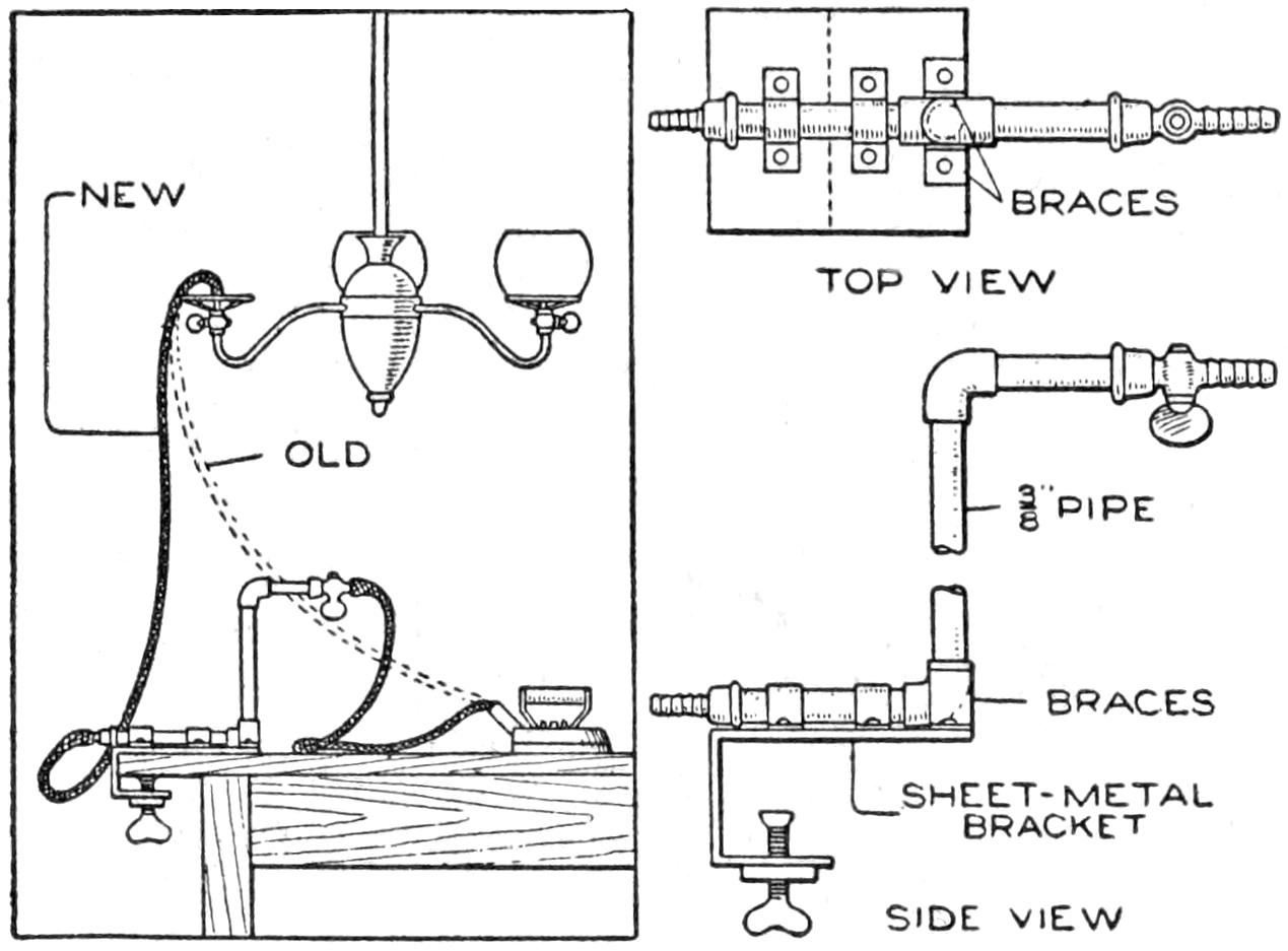
The Bracket Gives Greater Freedom in the Use of the Gas Iron
In a home where it was customary to use an overhead gas fixture for the attachment of the gas iron for ironing clothes, it was found that mantles were frequently broken by the resulting jar. By making a bracket for the gas hose, which is fastened to the end of the ironing board or to the edge of the table, this trouble was remedied. The new arrangement gave much greater freedom in the use of the iron. The bracket can be removed quickly and fitted to a bench for use in the shop.—M. J. F. Schramm, Ridgewood, N. Y.
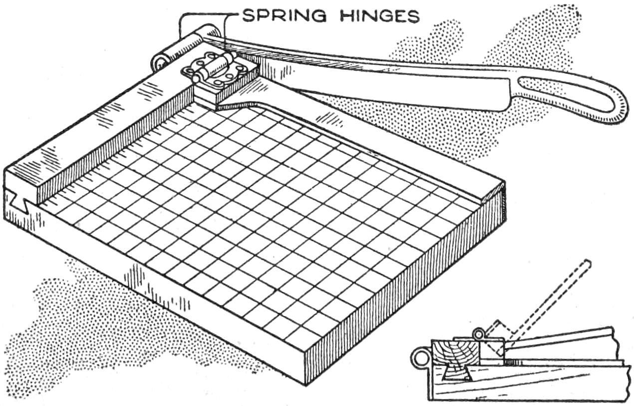
The Spring Hinge Presses the Guide Down on the Print being Cut
Having an old but still serviceable photograph trimmer, with which it was difficult to trim prints uniformly and quickly, I made a guide for this purpose and fitted it to the board, as shown. The guide is a strip of wood, ¹⁄₄ in. thick, and is fastened to the cleat with a spring hinge, mounted on a block. Although it is not transparent, like the best commercial devices of this kind, it gives good service.—R. B. Manck, Nazareth, Pa.
To reunite the particles of mercury or other liquid, which have become separated in a thermometer, raise it to the level of the extended arm, the bulb outward, and jolt the tube with a quick downward stroke. Repeat this, not too vigorously, until the liquid returns to its proper position.
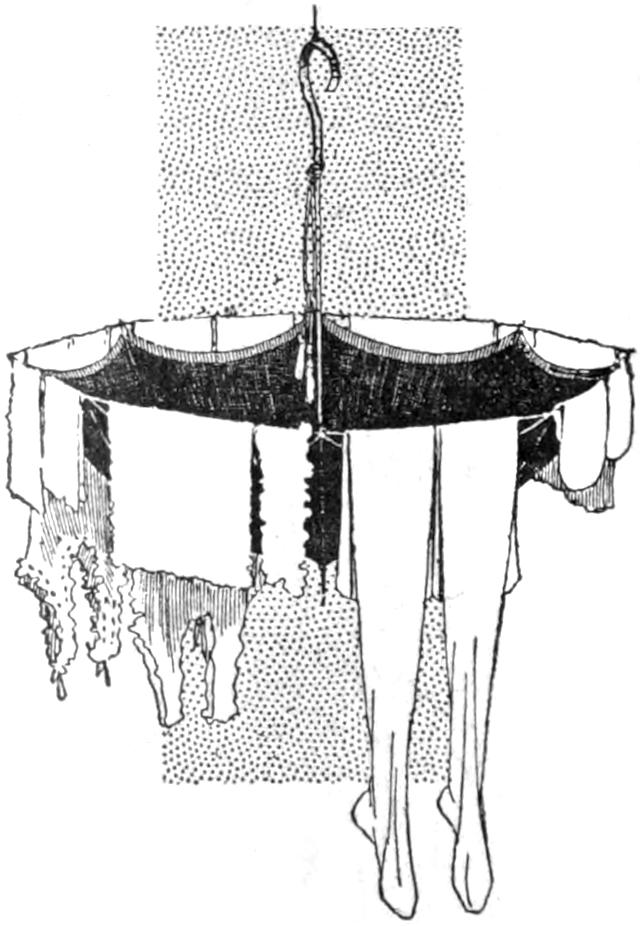
A clothes drier that can be carried in a purse or a vest pocket will appeal to travelers, and persons living in small quarters. An umbrella, four yards of strong wrapping twine, and several small brass rings are required. Knot the rings into the twine at intervals, measuring the distance between the rib points of the umbrella, and hook the twine to the points by the rings, as shown, providing considerable drying space for small articles. Hook the umbrella handle over a suitable support, or tie it carefully to the supporting pipe of a light fixture in the middle of the room, ready for the articles to be dried. The twine may also be wrapped around the points, but it is better to carry a line with rings attached.
¶By reversing the handle on a dust brush which has been worn near the point, additional wear may be obtained.
[367]
In painting, and other work where a brush is used, it is often desirable to stiffen the bristles. This may be done readily by fixing a band of sheet metal over the brush, to slide tightly. By adjusting it, the length and stiffness of the part of the bristles used may be controlled.
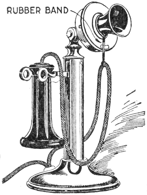
It is exasperating to pick up the telephone receiver to answer a call and find the cord twisted or wound around the telephone standard. A long receiver cord will not tangle if a rubber band is used to support it, as shown in the sketch. The elastics permits considerable play, and if the fullest extension of the cord is desired, it may be supported on several linked rubber bands, on the left of the standard.—K. M. Coggeshall, Webster Groves, Mo.
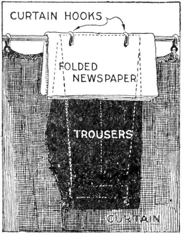
The berth of a sleeping car is usually provided with a coat hanger, but if there is a rod on it for trousers, there is nothing to keep them from slipping off. By removing two of the curtain hooks, hanging the trousers over the curtain pole, and replacing the hooks over the trousers, a satisfactory hanger is obtained, which will not permit them to slip down no matter how rough the road.
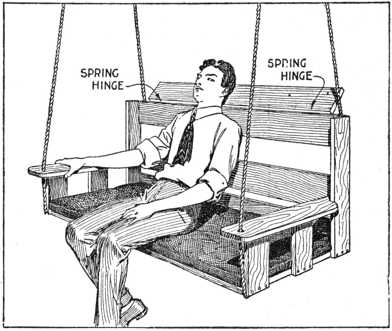
The Hinged Board Provides a Comfortable Headrest, and Is a Safety Feature
Here is a “peach” of a homemade porch swing—a shock-absorbing species. The top board is attached with springy hinges, and affords an ideal headrest. It also tends to prevent children from climbing over the back.—H. W. Hart, St. Paul, Minn.
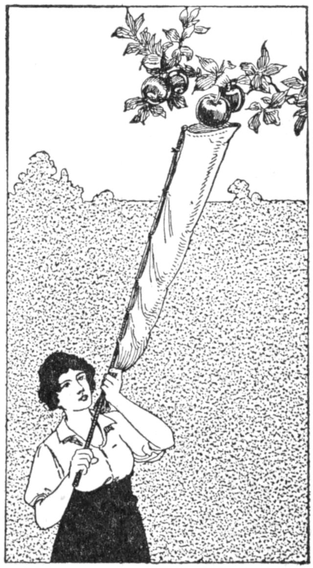
For picking fruit without bruising it, in the home garden, or for exhibition purposes, the fruit-picking pole shown in the sketch is useful. A wire ring is fixed to the top of the pole, and the bag, suspended from it, is fastened to the pole at intervals. The fruit is removed by means of the ring and drops to the bottom of the chute, which is held closed by the hand. For picking large quantities of fruit a receptacle is carried by the picker.—Mrs. Ella L. Lamb. Mason, Michigan.
[368]
A set of electric dinner chimes is a welcome and useful addition to many households, and may be made at a trifling cost by the average person handy with tools. The completed article is shown in Fig. 1, the details in Fig. 2, and the wiring diagram in Fig. 3. The woodwork is of ¹⁄₂-in. stock. The back A, Fig. 2, is 1¹⁄₂ in., by 9³⁄₄ in. long. The ends may be shaped to suit the builder’s fancy. The shelf B is 4 in. square, and is fastened to the back piece 2¹⁄₄ in. from the upper end. It supports the magnets C, which are made on cores, ³⁄₈ in. in diameter and ³⁄₄ in. long, with ends ¹⁄₁₆ in. by 1 in. in diameter. The spools are wound full of No. 28 silk-covered copper magnet wire. These coils mounted on the shelf by means brass straps D. Four magnets are used, the forward one being omitted in Fig. 2.
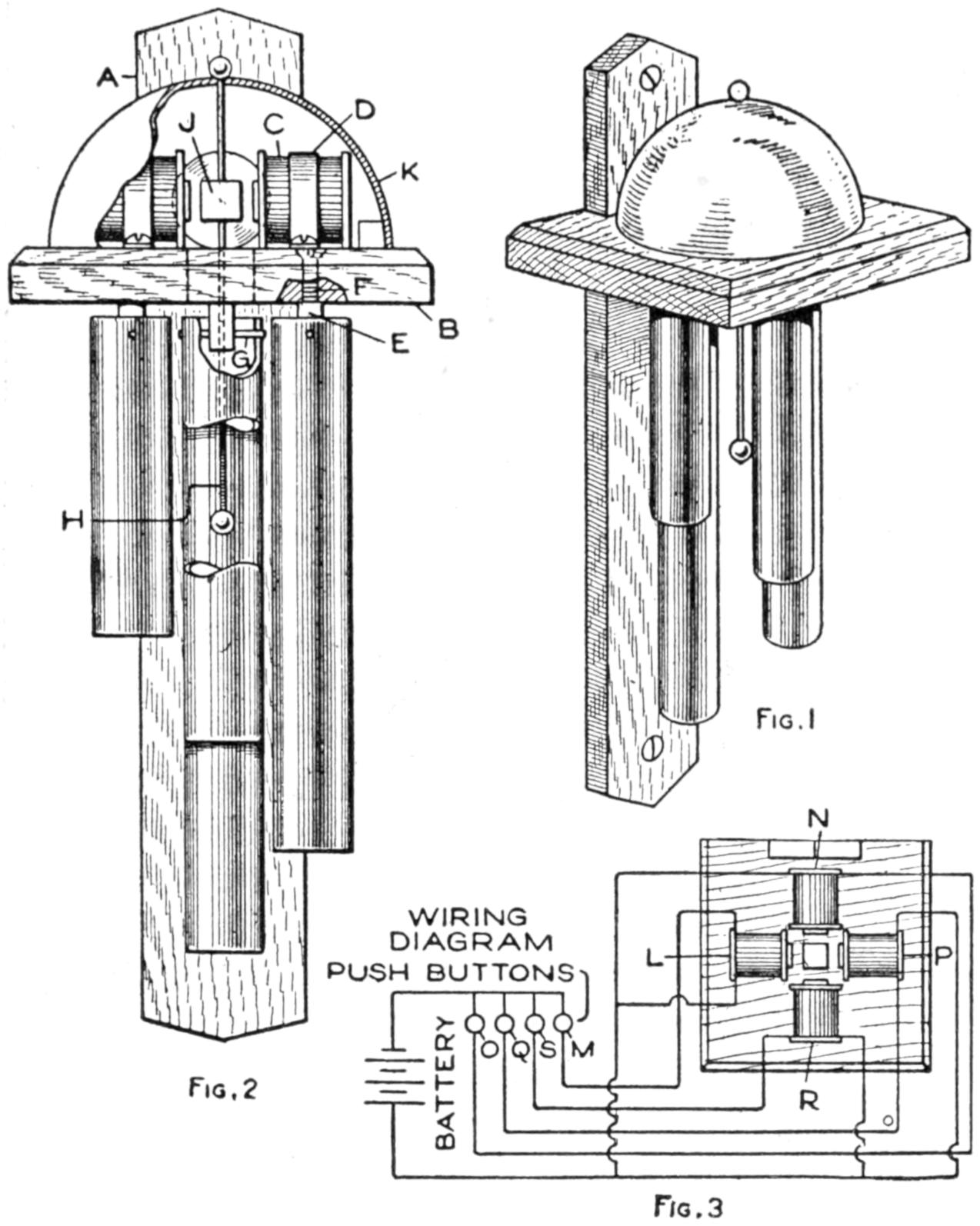
Fig. 1
Fig. 2
Fig. 3
When the Buttons are Pressed, Tones are Given Forth by the Electrically Operated Gongs
The supports E, for the tubes, consist of ¹⁄₂-in. lengths of ¹⁄₄-in. square brass rod. One end of the rod is drilled and tapped for an 8-32 screw which holds the support in place. Drill a small hole, ¹⁄₄ in. from the end, for the pin G, made of steel wire. The tapper H is made from a 4¹⁄₂-in. length of stiff iron wire; 1¹⁄₄ in. from one end a ³⁄₈-in. cube of iron, J, is soldered, the wire passing through it. The ends of the wire are fitted with balls as shown. A nickeled gong, K, covers the four magnets. The end of the tapper is passed through the hole in the gong and the ball riveted into place.
Four ³⁄₄-in. diameter tubes are used, respectively 3, 4, 5, and 6 in. long. When the apparatus is assembled as shown, and one of the magnets is energized, the latter will draw the iron cube J toward it, and the tapper will strike one of the tubes.
To control the current supplying the magnets, four small push buttons mounted on a wooden base are used. They are wired up with the battery and coils, as shown in Fig. 3. A wire from each of the coils runs directly to one terminal of the battery, the other wire from each coil being connected to a separate push button. The other sides of the push buttons are connected to the battery. By this means any of the magnets may be energized at will, the coils and corresponding push buttons being marked L and M, etc., alphabetically.

Musicians sometimes have trouble in turning over sheet music quickly. Here is a simple way to turn the leaves quickly and easily: Paste a tab on the edge of each sheet, as shown. The first sheet is tagged at the top, the second in the middle, and the last sheet at the bottom, like a letter file. Where there are many sheets, it is easy to grasp the upper tab, on each successive sheet.—M. W. Meier, Chicago, Ill.
[369]
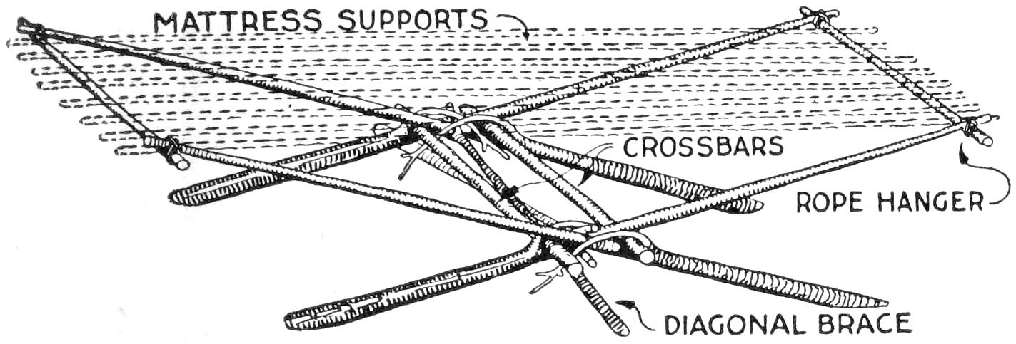
The Camp Bed can be “Knocked Down,” or Transported Considerable Distances as It Stands
In many camping places, balsam branches, or moss, are available for improvising mattresses. Used in connection with a hammock, or a bed made on the spot, such a mattress substitute provides a comfort that adds to the joys of camping. A camp hammock, or bed of this kind, is shown.
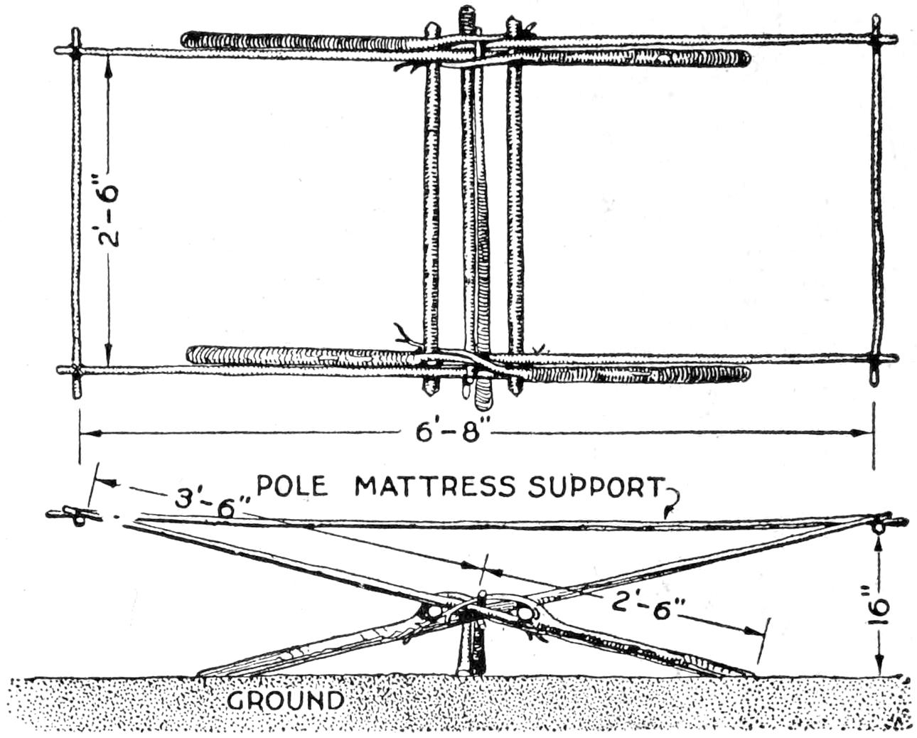
The Poles are Selected Carefully and Set Up with Stout Cross Braces at the Middle, and Lighter Ones for the Mattress Support
To make it, cut four 6-ft. poles, of nearly the same weight and 1 in. in diameter at the small end. These saplings should have a fork about 2¹⁄₂ ft. from the lower ends, as resting places for the crossbars, as shown. Then cut two poles, 2 in. in diameter and 3¹⁄₂ ft. long, and two smaller poles, 3 ft. long. Also cut two forked poles, 4¹⁄₂ ft. long, for the diagonal braces. Place two of the long poles crossing each other, as shown, 1 ft. from the ground. Set up the second pair similarly. Fix the crossbars into place, in the crotches, the ends of the crotch branches being fastened under the opposite crossbar. The end bars are fixed to the crossed poles by means of short rope loops. The mattress is placed on springy poles, 7 ft. long and 2 in. apart, alternating thick and thin ends. The moss is laid over the poles, and the balsam branches spread on thickly. Blankets may be used as a cover.—J. S. Zerbe, Coytesville, N. J.
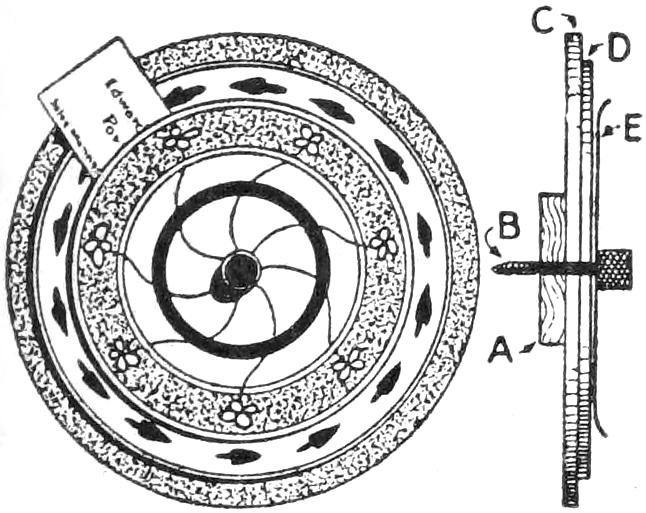
A holder which may be ornamented and trimmed with leather or other materials, was made of several disks of wood, joined at the center by a thumbscrew, and provided a neat place for calling cards, post cards, etc. The block A, which fits against the wall, is ³⁄₈ in. thick and 2 in. in diameter. The disk C is ¹⁄₄ by 7 in., the disk D, 6 in., and the metal disk E, 6 in. in diameter. The edge of the metal disk, which may be of ornamented or etched brass, or copper, is curled forward as shown. The thumbscrew B holds the disks together and fastens them to the wall.—James E. Noble, Portsmouth, Ontario, Can.
Litmus paper laid on glass, and moistened with a weak solution of sodium sulphate can be used to test the polarity of a direct current. If the two conductors are touched on the moistened paper, the latter will turn red at the positive, and blue at the negative conductor.
¶A berry stemmer made of a small pair of tweezers is useful for removing superfluous buds from garden flowering plants.
[370]
The hook A is made of tempered brass or steel wire of a gauge sufficient for the size of the fish to be caught. A wire of No. 18 gauge is about right for ordinary fishing, with a No. 20 or 22 gauge for the trigger. Hooks, C C, can be soldered on the points to angle for larger fish. Barbs are not required for smaller fish.
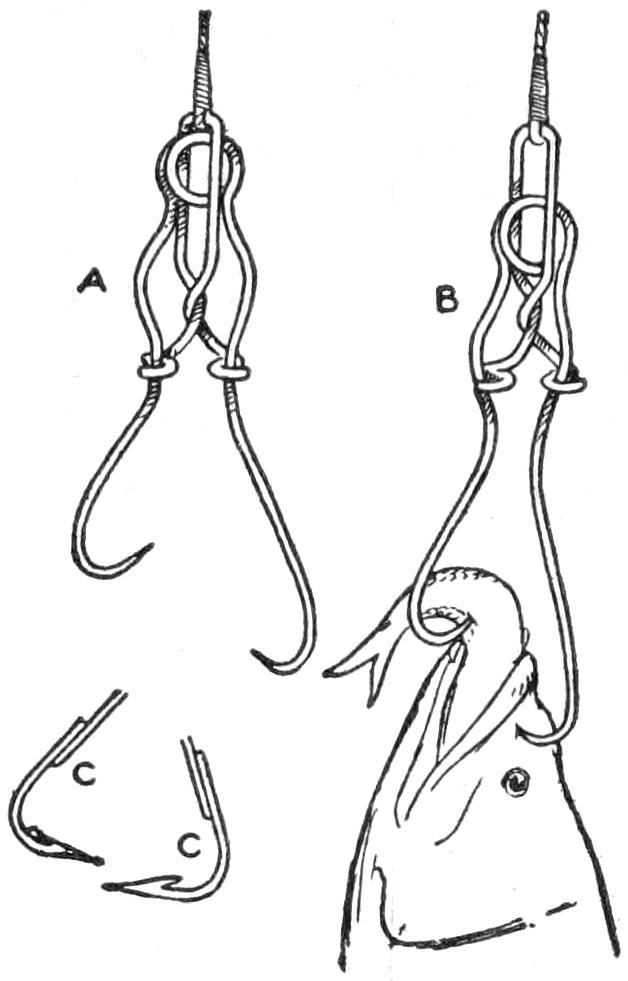
Such a hook will catch the fish, even if they only nibble, and is especially good for fishing through the ice. Use a bob and a pole, and bait the short hook with a minnow or worm. The extreme length of a hook for catching a 1-lb. fish should be 3 in. Fasten the line as shown at B.—Contributed by Robert C. Knox, Waycross, Ga.
The sketch illustrates an inexpensive temporary binder for periodicals, magazines, newspapers, etc. It consists of four parts, namely, two sheets of cardboard, A, the size of the magazine to be bound, and two pieces of linen or tape, B. A slot is cut in each corner of the cardboards about 1 in. from the edge. The tape is run through these slots in the manner shown.
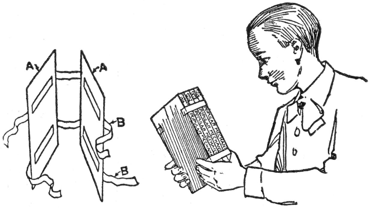
The Binding is Only Temporary to Keep the Magazines in Good Condition for a Complete Volume
The magazine numbers, as they are received, are placed on the back cardboard, building them up consecutively as they come. The ends of the tape are tied to hold them together. The backbone is open and the contents are readily seen.
The sliding of the tape in the slots provides a means of holding from one to as many copies as may be desired, and they are kept in good condition until a complete volume is compiled, when a more permanent binder can be made.
Instead of tape a leather strap can be used with a buckle. The tapes can be fastened to one of the cardboards, allowing one end only to be movable.
A most practical and satisfactory way of using a stool in a small workshop is shown in the illustration. In much of my small work at the bench I find it an advantage to sit, and for that purpose I purchased a small stool. My lathe is operated by a geared foot motor provided with two foot levers which may be operated singly in a standing position or both at a time when sitting. The attachment shown converts the stool, the seat of which is too low except for bench work, into a comfortable and neat seat for working at a lathe. The sketch is self-explanatory.
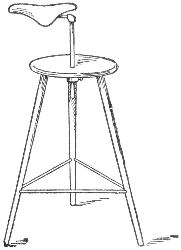
A plate with a setscrew is mounted under the center of the stool seat, through which a hole is bored for the seat post. Two pieces of iron pipe, an elbow and an old bicycle saddle constitute the remaining parts of the device. Provision is made for adjustment as to height, and the position of the saddle may be changed in the ordinary way by using a wrench on the part which grips the horizontal length of pipe, just the same as the seat on a bicycle-seat post is adjusted.
[371]
The rivets in a couch come loose and work out quite often, leaving it loose and wobbly. To make rivets fit properly by hammering them into place is almost impossible and to repair the couch with stove bolts makes an unsightly job. A very good repair and one that will make a couch rigid and strong again is by the use of ordinary brass binding posts from old dry-battery cells instead of rivets. These can be easily placed without tools.—Contributed by G. H. Clemmons, Storm Lake, Iowa.
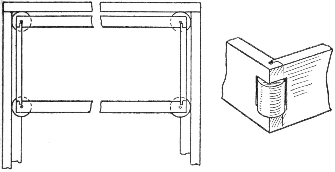
The Spool in Each Corner of the Tray Rolls against the Side of the Tool Chest
The slide trays of a tool chest, especially if they are wider than they are deep, are apt to bind. To remedy this trouble, I procured four ordinary thread spools and inserted them in openings cut for them in the corners of the tray. Holes were bored through the corners for pins to hold the spools in place.—Contributed by J. V. Loeffler, Evansville, Indiana.
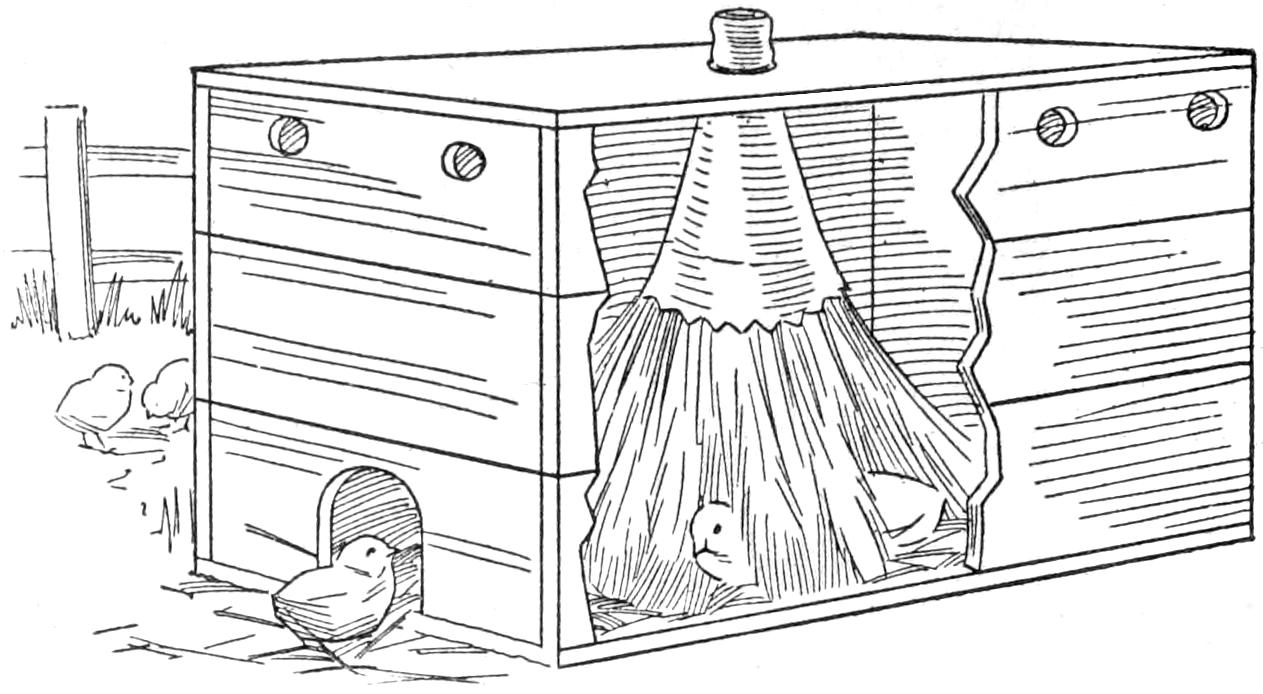
The Feathers of the Duster in the Center of the Box Take the Place of Those of a Hen
A very effective brooder can be made of an old feather duster hung in a box so that the tips of the feathers will come close to the bottom. The brooder consists of a wood box about 1 ft. high. The cover is removed and a hole cut in the center to receive the shank of the duster after cutting its handle off. This makes an excellent substitute for the feathers of the hen. Some finely cut hay, or sand, is placed beneath so as to bring the level up sufficiently for the chicks to run among the feathers. For ventilation, bore some holes in the sides of the box near the top and cut a small opening for an entrance. For convenience in cleaning, the cover should be hinged.—Contributed by Wm. T. Miller, Roslindale, Mass.
Procure a piece of ¹⁄₄-in. round steel, about 5 in. long, and file one end of it square for about one-third of the length, so that the diagonal of the square part is less than the diameter of the rod. Cut about 8 washers each, of brass and iron, from material, ¹⁄₈-in. thick. Make the hole in the washers square to fit the square on the rod. The washers can be cut out roughly on the outside, but they must be larger than the diameter of the rod. Place the brass and iron washers alternately on the rod, beginning with a brass and finishing with an iron washer, which latter is held in place by riveting the end of the rod on it.
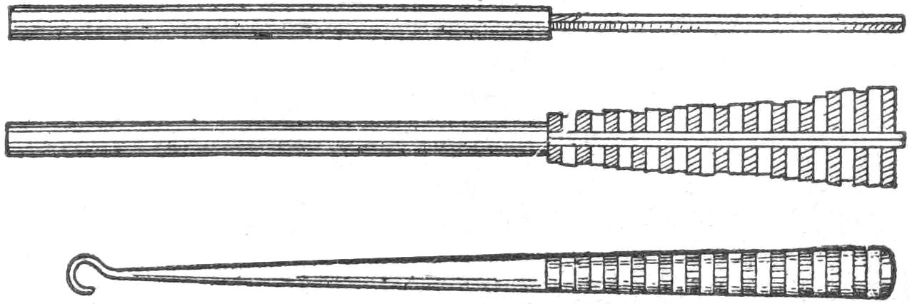
The Different Colors of the Metals When Polished and Buffed Give the Hook a Neat Appearance
The washers are then filed round, and the remaining end of the rod is tapered. The pointed end is bent into a hook. The whole length is then polished and buffed.—Contributed by H. W. Hankin, Trail, Can.
[372]
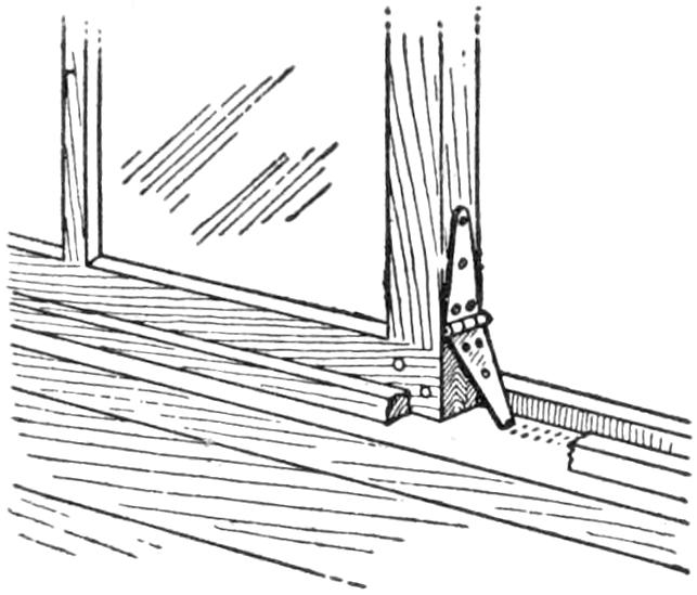
A simple catch for fixing windows of the horizontal sliding type so that it is difficult to pry them open is shown in the sketch. It is made of an old hinge, one end of which is sharpened so as to engage the surface of the frame on which the sash slides. When not in use the hinge is folded up. It can be used to set the window at various points when it is desired to have it partly open.—T. H. Linthicum, Annapolis, Md.
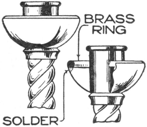
A brass candlestick brought to me for repairs had lost a crownlike bit of ornamentation once fitting on the top of the grease cup. To make a finish at this point I soldered therein a heavy brass nose ring. The soldering being concealed on the under portion, the effect was very good, and strength was added to the thin brass cup, preventing possible denting of the edge.—James M. Kane, Doylestown, Pa.
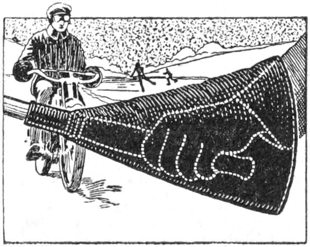
When riding my motorcycle in cool weather, my hands became very cold, and in order to overcome this, I had guards, like that shown in the sketch, made of oilcloth. A piece, tapered from 10 in. at one end to 4¹⁄₂ in. at the other, and 12 in. long, was formed into a cone, the smaller end being fitted, with an elastic band, over the handlebar. The guards keep the hands comfortable without gloves in cool weather, and, with gloves, are of great service in the winter.—George Westaway, Davenport, Ia.
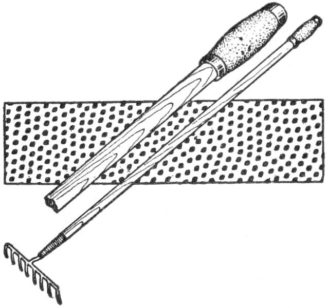
By fitting a bicycle handle to the end of a rake handle a grip is provided that is comfortable in the hand when considerable raking is to be done. The sketch shows the grip attached. Several small brads were nailed through the handle and countersunk so as not to injure the hand. This prevented the grip from becoming loosened easily.
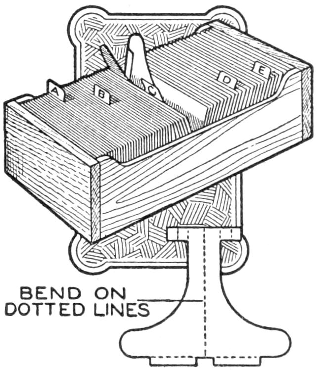
A marker which is adapted for use in files of various sizes is shown in the illustration. It may be made easily of medium-weight cardboard, cut to the shape shown in the diagram below and bent as indicated. The marker is inserted at a point in the index from which a card or other filed material has been removed. It is of such a size that, when in use, the tab projects only enough to be recognized, and the marker may be left in the drawer so as to be convenient for future use. The sketch shows the marker partly withdrawn. The small projections shown in the diagram are important in that they act as springs when the marker is in use.—John B. Wade, Wellington, Kan.
¶Gaskets cut from old inner tubes are satisfactory for water connections.
[373]
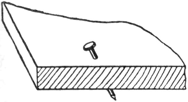
A nail driven so that it crosses the grain, as shown in the sketch, is not likely to split the board through which it passes. The splitting often results when the nail is driven straight. The nail should be started at different angles according to the grain of the wood.—Contributed by Chas. G. England, Washington, Pa.
Having four geese in a yard with chickens, I found that the chickens would not allow the geese to pick up the food. To feed the geese I placed the corn in the bottom of a pan and filled it with water. The geese will easily pick up the corn from under the water, where the chickens would not attempt to touch it.—Contributed by Walter L. Kaufmann, Santa Ana, Cal.
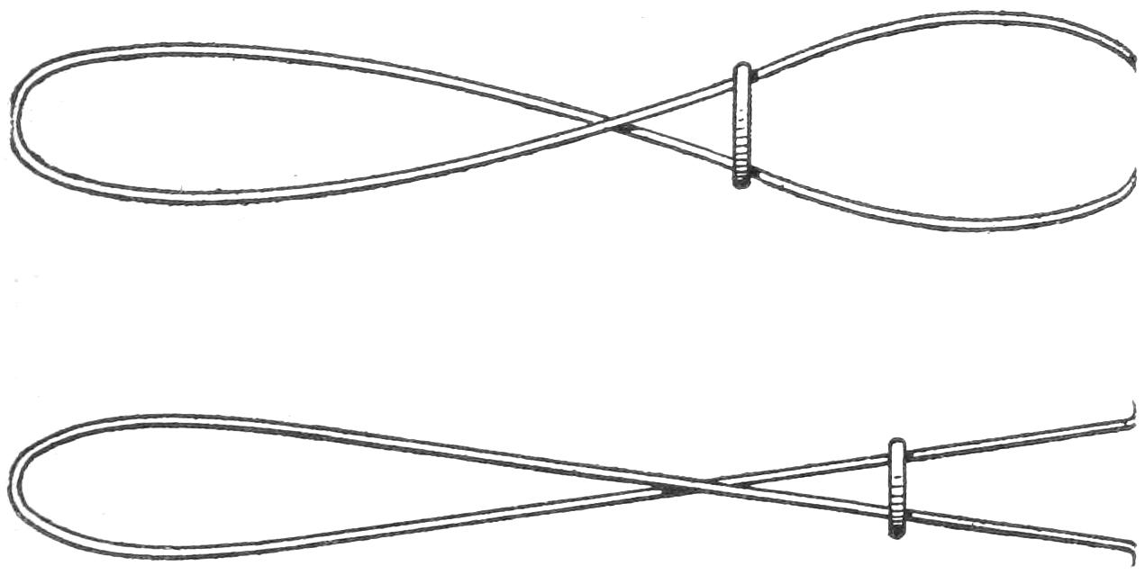
The Spring Wire is Bent So That the Points Turn In or Out as Desired
A good pair of calipers can be easily and quickly made by anyone in the following manner: Procure a piece of spring wire, about 15 in. long, and bend it as shown in the sketch, allowing the ends to point inward or outward as the style demands. A loop of heavy wire is fastened around the center so that it can be slid back and forth along the wire. This serves the purpose of an adjuster.—Contributed by Stanley Radcliffe, Laurel, Md.
In starting small plants to get them hardy and ready to plant in the early spring provide separate receptacles of paper, then the plant can be set out without trouble and it will grow as if it had never been moved. Procure some heavy paper and make the cups as shown in the sketch.
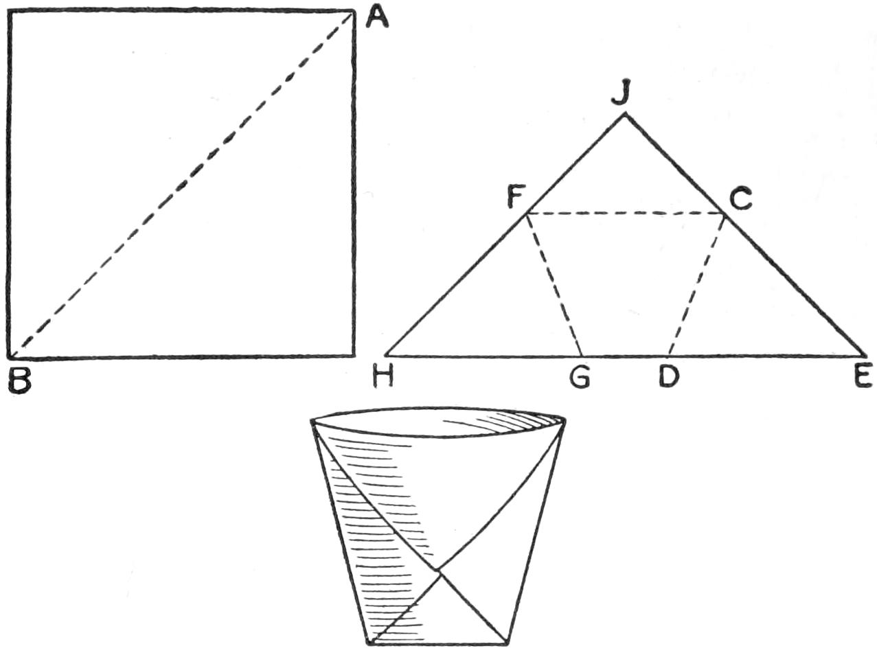
The Paper Cup Starts One Plant and When Reset No Damage Results from the Change
The paper is cut into squares, the size depending on the plant, and each square is folded on the dotted line AB. This forms a triangle of a double thickness. The next fold is made on the line CD, bringing the point E over to F. Then the paper is folded over on the line FG, bringing the point H over to C. This will leave a double-pointed end at J. The parts of this point are separated and folded down on the sides which form the cup as shown.
These cups are filled with earth and set into earth placed in a box. The seeds are planted within the cups. When it comes time for transplanting, the cup with the plant is lifted out and set in the garden without damage to the plant roots. The paper soon rots away and gives no trouble to the growing plant.
The stove is made of one piece of No. 6 gauge brass wire and a 6-in. length of ¹⁄₂-in. gas pipe, A. Drill six ¹⁄₁₆-in. holes in the side of the pipe, spacing them evenly. Turn a cap on one end of the pipe and fit a hose cock[374] on the other. Start with the ends of the wire and make one turn around the pipe, then make loops at both sides, to serve as feet, and shoulders, on which to set the bread in making toast. From this point, where the wires come together, twist them for a length of 6 in. They are then spread and formed into a circle about 4 in. in diameter. The other side, or upright, is made in the same manner as making the first part.
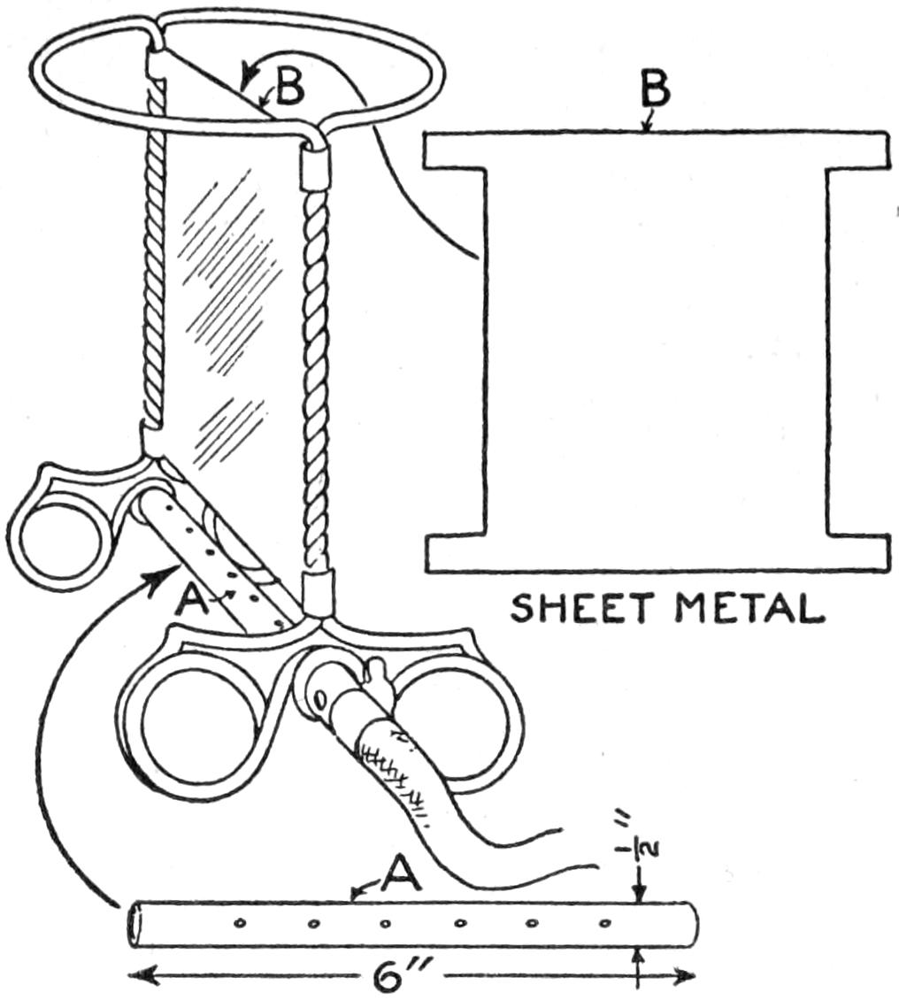
The Stove Takes the Place of an Electric Stove Where There is Only a Gas Supply
A piece of sheet metal, B, is cut to fit the space between the wires, allowing projections at the upper and lower outside edges for bending around the upright twisted wires. The entire stove can be nickelplated if desired. It can be used in the same manner as an electric stove and for the same purposes where a home is supplied only with gas.—Contributed by E. L. Douthett, Kansas City, Mo.
The sketch shows a method of making small castings that I have used for several years and the castings so produced are strong and very durable, almost equal to the ordinary casting. The idea may be of considerable value to inventors and home mechanics.
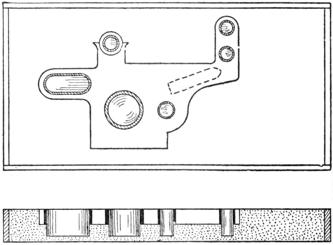
A Mold Made in Plaster without a Special Pattern and Run with a Soft Metal
The mold is of plaster of Paris, held in a wood frame or box, and all that is required in the way of a pattern is a plain block or anything that will produce an impression of the general outline of the casting, as shown in the sketch. After the impression is made the mold should be dusted thoroughly with black lead. The journal bearings are then located, holes drilled in the hardened plaster and wood pins set as shown. These pins must be of hard wood and of a diameter to suit the finished size of the bore. Brass tubing of a suitable size is cut off to the length required and placed on the wood pins. These pieces of tubing will be the brass bushings in the finished castings. Babbitt metal is melted and poured into the mold. Before pouring the metal it is well to be sure that the plaster is thoroughly dry.
The mold is as shown, and the upper side of the metal is at all times exposed to the air. This makes it necessary to have all core prints on the under side, as this side will be the one in view when the casting is finished, and the upper side, as the casting lies in the mold, will be the inside or unexposed side. In case of curved work, reinforcing strips of sheet brass should be placed in the mold and imbedded in the casting, as shown in the sketch by the dotted lines.
A little practice will enable anyone to produce very neat cored castings. and when the brass bushings are fitted to size and faced off, and the casting painted, a piece will be produced that[375] will compare in finish and general usefulness with anything of the nature that could be bought. Do not treat the brass tubes with soldering flux unless necessary, for they should be removable so that they can be replaced when worn.—Contributed by J. B. Murphy, Plainfield, N. J.
Having a rush order for a large quantity of post cards, I was compelled to adopt some way of making the prints quickly. As I was in a place where a printer could not be secured for several weeks, I set about making one, with good results, as shown in the illustrations.
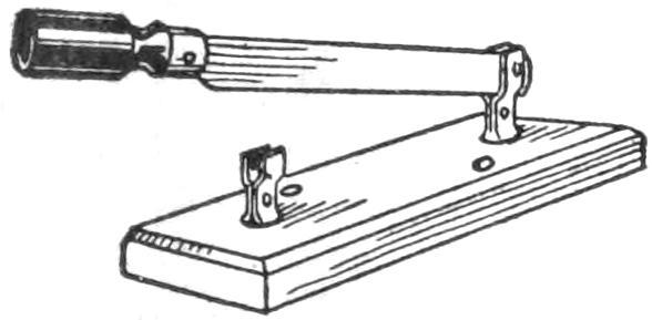
Fig. 1
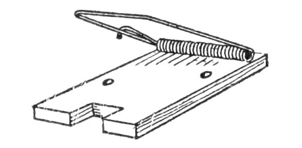
Fig. 2
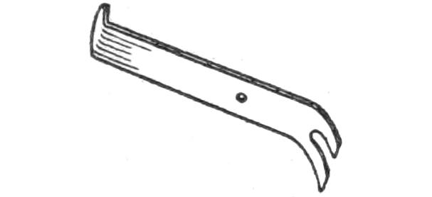
Fig. 3
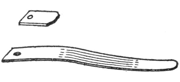
Fig. 4
Parts for Making the Switch So That It will Operate Automatically as the Cover is Moved
I first secured an ordinary soap box and took it apart, being careful to keep the boards whole, then rebuilt it to make a box with ends measuring 12 in. square, and 14 in. in length. In one end I cut a large hole to admit a 60-watt tungsten globe, then, taking another board, I fitted a knob and hinges to it and used it for a door. The other end of the box was centered and a hole bored large enough to admit an ordinary socket. Another hole was bored, 4 in. to the right, for another socket. A much heavier material was used for the lid than for the box, being at least ⁷⁄₈ in. thick. A piece of double-strength, clear glass, 8 by 10 in. in size, was procured and set in a hole cut in the cover so that its upper surface would be flush.
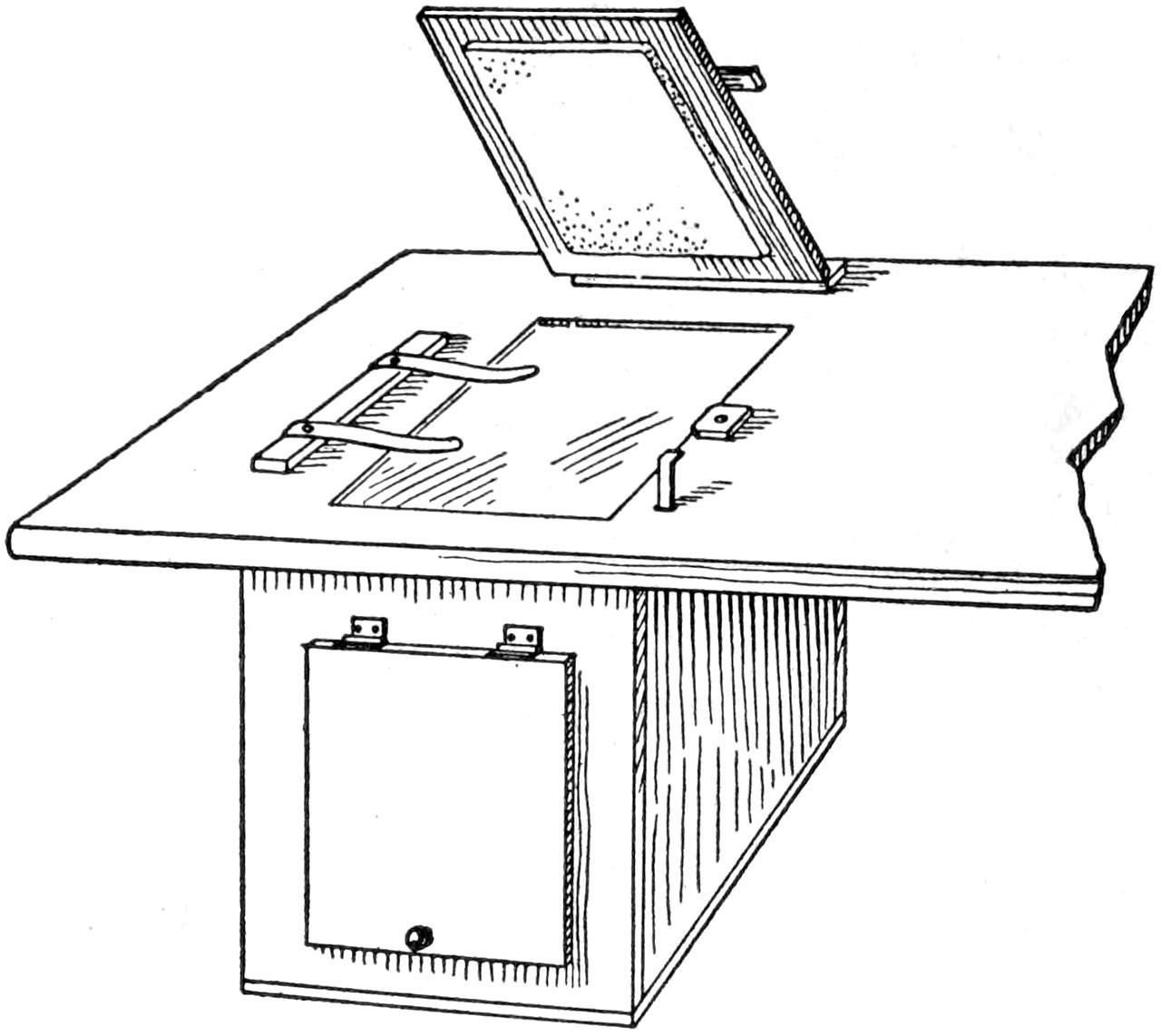
The Printer may be Set in the Table Top or Used Separately, as Desired
An ordinary single-pole switch was secured, as shown in Fig. 1, also a small mousetrap, as shown in Fig. 2. The front part of the trap was sawed off so that only the spring was utilized. The base of the trap was then cut out to fit snugly on the base of the switch, into which two corresponding holes were bored for the screws. The next thing was to secure several clips, which were cut from sheet brass, to operate the switch, and a lever to control the switch, as shown in Fig. 3. The lever is 1 in. wide and 4 in. long, having a slot at the bottom, to slip easily over the lever handle in the switch, and a hole, drilled 1 in. above the slot, to admit a nail to keep the spring from throwing it out of position. The clips for holding the films, or plates, are shown in Fig. 4.
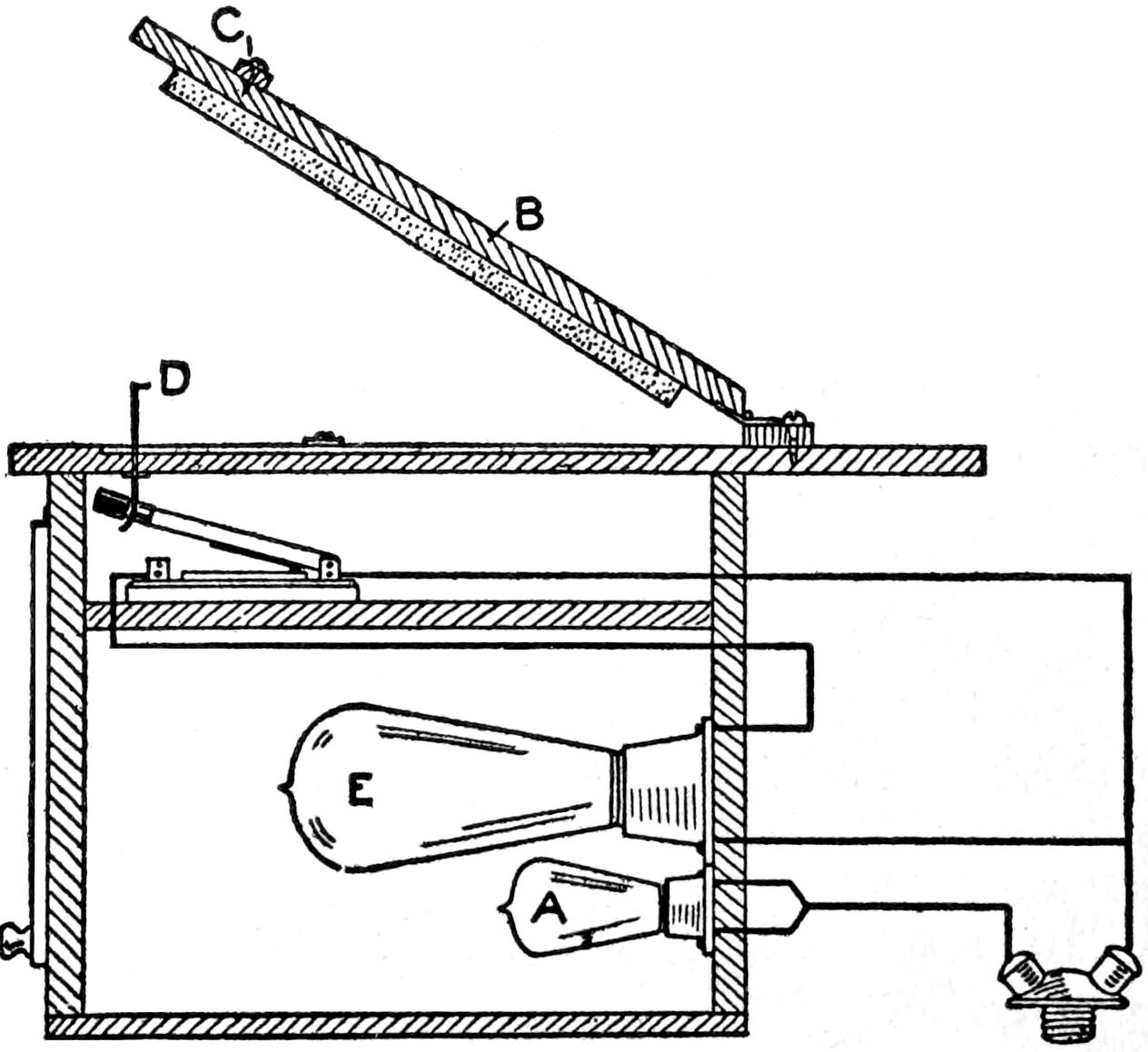
Side View of the Printer, Showing Parts Assembled and the Main Line Connections to the Globes
After securing a double socket, of which there are many types, a few yards of lamp cord, a piece of felt, 6 by 8 in. in size, and two ordinary lamp[376] sockets, I was ready to assemble the printer. The switch was then placed on a board of the same width, the spring of the trap placed on top of it and then fastened with screws. This board was then cut off the length of the inside of the box and fastened in place, with the switch and trap spring on top.
The ruby light A burns all the time, acting as a pilot in placing the negative. When the cover B is lowered, after placing the paper, the felt pad on the under side holding it secure, the projecting arm C comes in contact with the switch lever D and makes the connection to the tungsten light E. After the proper time for the exposure has been given the cover is raised and by this action the tungsten light is automatically shut off, leaving only the red light burning. With a 60-watt lamp I secure a print in about 3 seconds, which is fast enough. Of course, by using a larger lamp, the time could be reduced to a second or more, according to the size. The time given was obtained by experience in using ordinary brands of papers.—Contributed by Harry Marcelle, Honolulu, H. I.
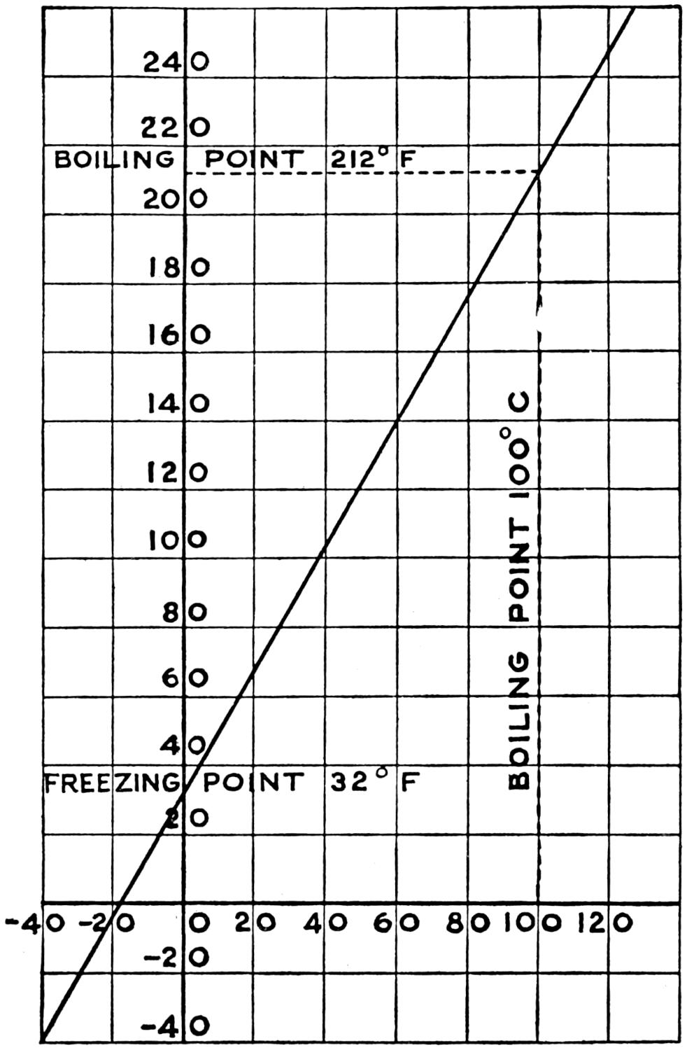
The Readings can be Transposed from Fahrenheit to Centigrade or Vice Versa Instantly by the Use of This Scale
It is often necessary for the amateur scientist to transpose a temperature reading from the Fahrenheit to the centigrade scale, or vice versa. This is easily accomplished by means of the diagram without the use of a formula. The centigrade readings are given on the horizontal axis and the Fahrenheit readings on the vertical axis. The temperature readings are the same at minus 40 deg. and from that point on the Fahrenheit readings equal nine-fifths of the centigrade plus 32. This reading is instantly seen by the scale.—Contributed by James F. Boyd, Ann Arbor, Mich.
The magazines I used in the shop, for making a few things from plans, became so soiled that they were unfit for the library. I now keep them clean by using a covering made of an old picture frame from which the back was removed and a plain glass inserted in its place. This is placed over the magazine or other plans on the bench and keeps them clean, dustless, open and flat.—Contributed by H. J. Blacklidge, San Rafael, Cal.

Many times one has use for an eyebolt when there is none at hand. Eyebolts of almost any size can be quickly made of a spring cotter. Simply thread the end, as shown, and use a nut and washer.—Contributed by Chas. G. England, Washington, Pa.
[377]
Tan-shoe polishes seem to rub the dirt into the leather and to darken it in a short time. Tan shoes can be kept clean and well polished without losing their original bright tan color if treated in the following simple manner. Instead of using tan polish on a new pair of shoes, dampen the end of a soft clean cloth, and rub a small portion of the leather at a time with the moist end and then rub briskly with the dry end. In this way tan shoes can be kept clean and nicely polished like new.—Contributed by John V. Voorhis, Ocean Grove, N. J.
It is easy to fool one’s friends with the little joker made to trap a finger. It consists of a piece of paper, about 6 in. wide and 12 in. or more long. To prepare the paper, cut two slots in one end, as shown, and then roll it up to tube form, beginning at the end with the cuts, then fasten the end with glue. The inside diameter should be about ¹⁄₂ inch.
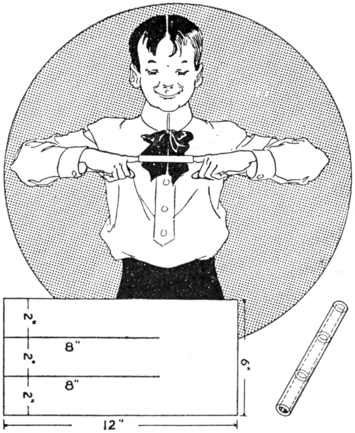
It is Easy to Insert a Finger in the Tube, but to Get It Out is Almost Impossible
When the glue is dry, ask some one to push a finger into either end. This will be easy enough to do, but to remove the finger is a different matter. The end coils tend to pull out and hold the finger. If the tube is made of tough paper, it will stand considerable pull.—Contributed by Abner B. Shaw, N. Dartmouth, Mass.
¶When mercury is spilled it can be picked up with a medicine dropper.
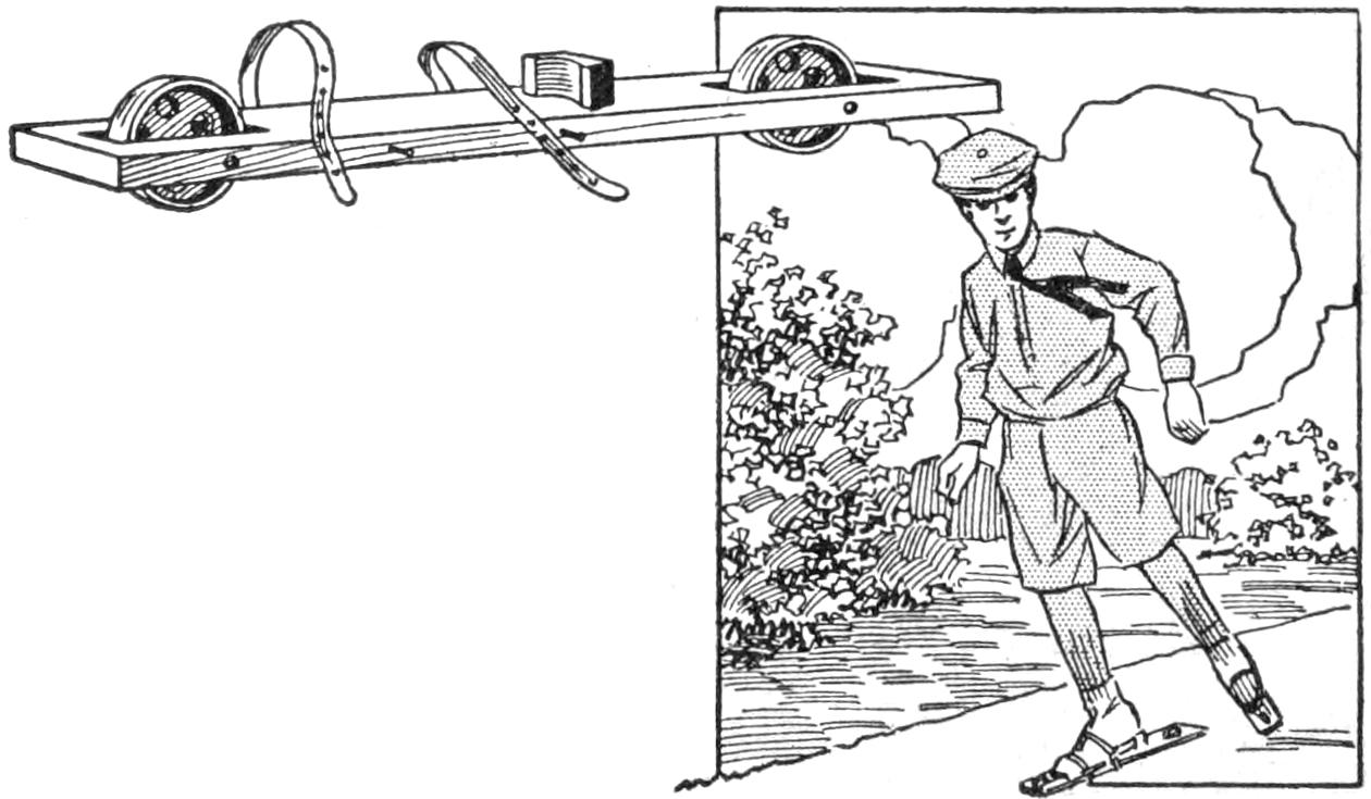
Wheels Fitted into the Ends of a Long Board, to Make a Roller Skate
The long wheel base of the roller skate illustrated makes it quite safe and will prevent falls. The construction of these skates is simple, the frame being made of a board, 2 ft. long, 3 in. wide and 1 in. thick. Holes are mortised through the ends to admit the wheels. A small block, cut out on one side to fit the heel of the shoe, is securely fastened centrally, for width, and just in front of the rear wheel on the board. Two leather straps are fastened to one side of each board, to fasten the skate onto the shoe. The wheels can be turned from hard wood, or small metal wheels may be purchased, as desired. The axle for the wheels consists of a bolt run through a hole bored in the edge of the board centrally with the mortise.—Contributed by Walter Veene, San Diego, Cal.
¶The screw collar of a vise should be oiled at least once a month.
[378]
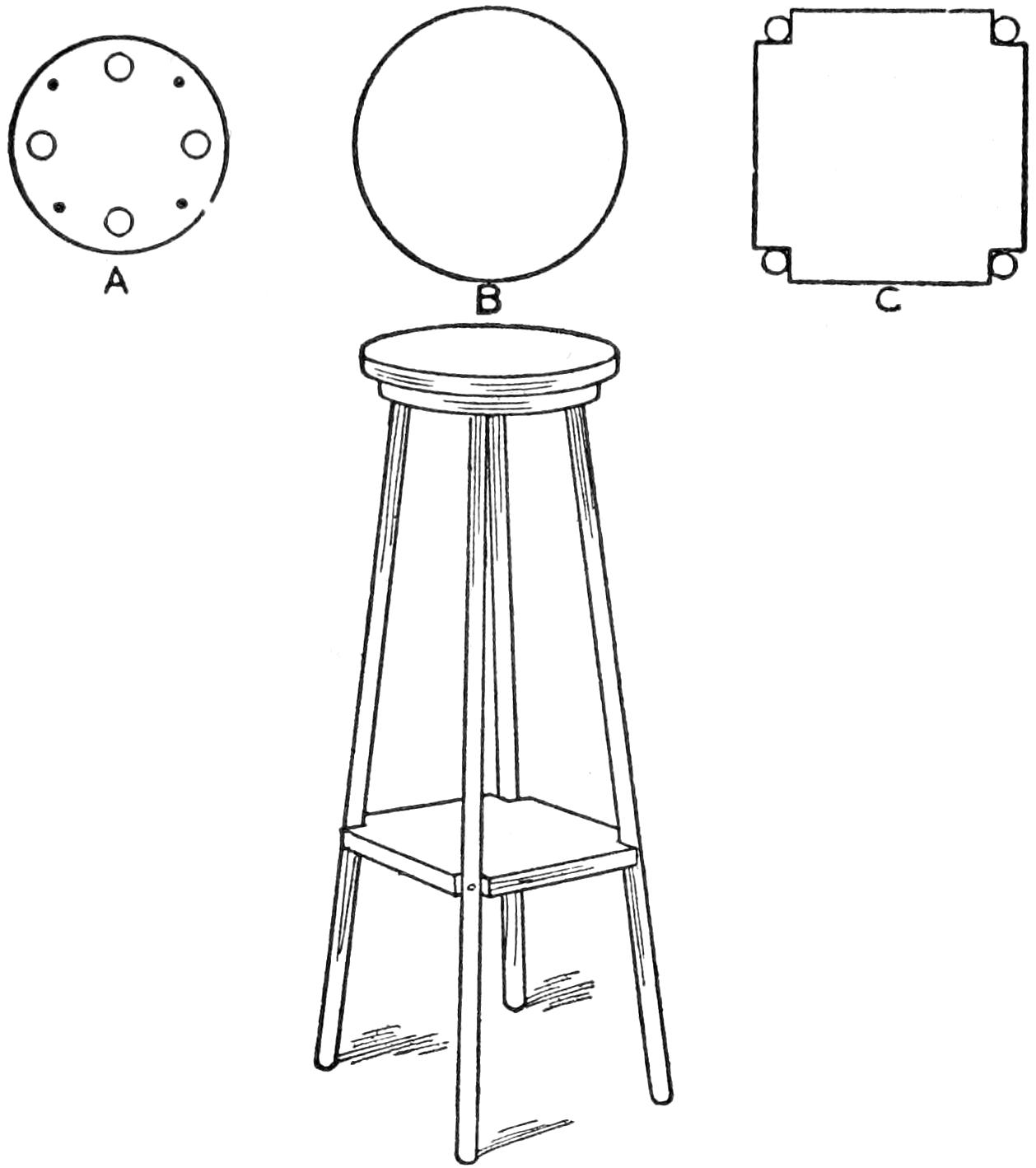
The cast-off handles of four old brooms, three pieces of board, cut as shown, and a few screws will make a substantial high stool. The legs should be placed in the holes, as shown at A, and secured with screws turned through the edge of the board into the legs in the holes. The seat B should be fastened over this and the legs braced by the square piece C. Screws are turned through the legs and into the square piece to keep it in position.
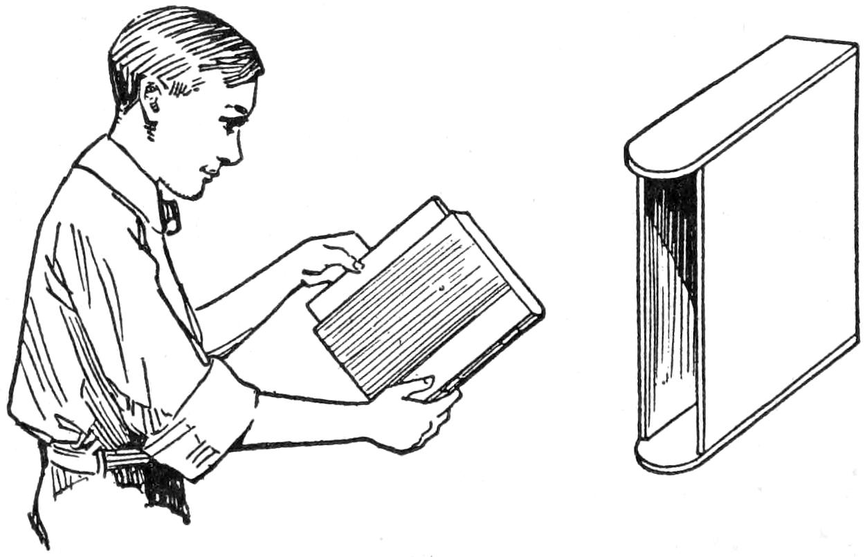
Several Boxes will Appear the Same as a Set of Books and will Preserve the Magazines
Desiring to preserve magazine copies without binding them, I made up a series of boxes that gave the appearance of books, and placed the numbers in order in them as they were received. The sides of the boxes consist of two thin boards, a little larger than the size of the magazine to be placed in them. The ends are made of the same material, wide enough to equal the thickness of the copies to be placed in each box, four or six numbers, or a volume. One end of these pieces is made slightly rounding, and the pieces are then put together as shown.
The rounded ends of the end pieces and the opening between the sides are covered with a piece of cardboard or bristol board, to shape the back of the box like a book. The finished box is entirely covered, like a book, with cloth or imitation leather. The backs can be lettered and decorated to appear like a book.—Contributed by R. M. Guarino, New York City.

The Wire on the Creaser Presses the Paper into the Space between the Two Wood Pieces
A simple apparatus for creasing thin cardboard or heavy paper in a perfectly straight line without broken edges is described in the French magazine La Nature as follows: On a base of convenient dimensions are fastened two pieces of wood, well smoothed and of equal thickness, so that there remains a slot, about ¹⁄₈ in. wide, between them. At one end a hole is bored through these pieces for a shaft on which the creaser will turn. The creaser is made of a piece of wood somewhat longer than the baseboard so that a handle can be formed at one end. At the other end it is slotted for a piece of metal, perforated for the shaft and fastened with two pins or rivets, as shown. On the under side of the creaser a stiff steel wire is fastened so that it coincides with the slot. The wire is fastened by heating the ends red hot, bending them at right angles to the main part and driving them into the creaser.
¶A razorlike edge can be put on a knife blade by carefully stropping it without lubricant on a piece of smooth aluminum after first whetting on an oilstone.
[379]

ery few persons realize that the smoke issuing from chimneys is mainly coal gas carrying minute particles of unconsumed carbon that gives it a dark-gray color, containing, besides, some sulphur and sulphuric gases, carbonic-acid gas, and other impurities. It is only necessary to collect the impurities to get a gas that will burn with a bright flame.
The products obtained from a gas plant are gas, ammoniacal liquor, coal tar, and coke. Of 1 ton of coal, 1,500 lb. remains in the retort, or furnace, as coke; 20 gal. of ammoniacal liquor and 140 lb. of coal tar are taken from the cylinders and washers. When distilled, the ammoniacal liquor will yield close to 18 gal. of ammonia, which is used in the manufacture of artificial ice and cold storage. The coal tar will yield approximately 19 lb. of benzol, which is the base of all true aniline dyes; 6 lb. of naphthalene, commonly known as camphor flakes or moth balls, which also yields some dyes; 4 lb. of toluene, which is valuable as a solvent and is the base of saccharine, and about 2 lb. each of phenol (carbolic acid), pyrene, anthracene, xylenol, cresol, chrysene, and alizarin. The residuum is coal-tar pitch, used extensively as a binder for briquetting coal dust for household consumption, and also for roofing and street paving. From these various coal-tar products, dyes of every tint, shade and color are obtained, as well as other industrial chemicals, from flavoring extracts to perfumes, from volatile oils to high explosives, and from the sweetest of all sweets to the bitterest of bitter.
A model gas plant—one that will be instructive and in no way dangerous if proper precautions are taken—can be[380] built from a few fire brick, some pieces of pipe, and a few tin cans. Enough fire brick must be secured to build a furnace 14 in. square by 20 in. high, inside measurements. Build up the four walls on a level surface of the ground, laying the bricks with a cement mortar to seal them perfectly, as coal gas will find any small crevice and escape. For this reason it is best to build a second wall outside of the first and plaster the joint between them as it is built. When the four walls are finished, make a grate of fire brick in the bottom by setting the brick on edge and spacing them about ¹⁄₄ in. After the walls are dry, make ready the material for the fire. Place sufficient kindling on the grate to start a quick fire, then cover it with coal. When this is done, cover the furnace with a heavy piece of asbestos board large enough to reach the outside edge of the furnace walls. The board must be cemented to the top surface of the brick walls. Place the cement mixture on the wall top, then press the board on it, and place a weight on top until the cement becomes dry. The cement mixture should consist of one part cement to two parts of fine sand.
Procure a large can, such as used in canning tomatoes, having a diameter of more than 4 in. and with top and bottom whole; also two other cans, each having a capacity of 2 gal. with closed heads. Connect the first can to the furnace with a piece of 2-in. pipe, as shown in the illustration. The pipe can be bent for convenience, but in case such a piece is not at hand, regular pipe connections can be made with threaded ends, ells, waste nuts, etc. In either case, be sure to make the joints gas-tight. If a bent pipe is used, the ends can be cemented in the asbestos furnace top and the can top. Cut a hole centrally in the asbestos top and at one side in the can top. Fit one end of the pipe in the hole made in the asbestos and seal the connection with asbestos cement, then do likewise with the end that enters the can top.
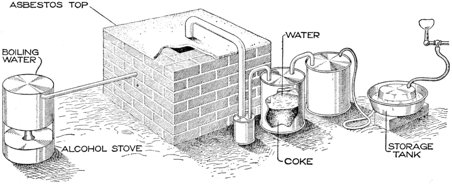
The Furnace Made of Fire Brick is Connected to the Condenser and Washers with Ordinary Iron Pipe through Which the Gases Pass After being Purified Before They Enter the Storage Tank
In connecting the first and second cans, use a piece of 1-in. pipe. This may be bent or connected with ells to form a U-shaped piece. In either case, one end should be longer than the other so that one will just pass into the first can, where it is sealed with asbestos cement, while the other end passes through the second-can top, where it is sealed, and extends to the bottom of the can. For the connection to the third can, make a hole in the top of the second can, but do not seal it up to the connection until the can is first filled with water to within 2 or 3 in. of the top. Also put powdered coke into the water, about halfway of the can’s height.
The connection from the second and third cans should be made of glass so that the gas can be observed passing through it between the cans. This is not absolutely necessary, however, and a piece of ¹⁄₂-in. iron pipe can be used instead. This pipe is connected in the same manner as that between the first and second, extending to the bottom of the third can and being sealed where it passes through the tops. The third can is filled with water to within 2 or 3 in. of the top.
The gas coming from the third can or washer, is ready for use, but as the pressure would not be uniform, a storage tank must be provided. To make a storage tank suitable for the needs of this small plant, procure two pans from 10 to 12 in. in diameter and from 3 to 4 in. deep. One pan should be a trifle smaller, so that it may be inverted in the larger pan, as shown. Make a connection from the third can with a rubber hose to the bottom of the larger pan, near the center, and use this pan as the bottom part of the storage tank. Pour into this pan enough water to make it 2 in. deep, invert the other pan and set it into the water. Attach a gas hose to the bottom of the inverted pan and fasten a gas jet into the rubber-hose end. This will make the gas plant complete and ready to operate.
To start the furnace, bore a hole in one side of the brick walls, about the size of an ordinary lead pencil, and insert a lighted taper to set fire to the kindling. There may be some difficulty[381] in getting the fire to burn at first, and it may be necessary to force considerable air in; however, when the fire is fairly started, it will burn freely and the gases will soon find their way through the first pipe to the condenser, which is the first can. There they will mingle and deposit some tar and ammonia, then flow out through the second pipe, up through the coke and water in the second can and through the glass tube, where they may be observed passing into the can of water, where some more tar and ammonia will be deposited. After leaving this can the gas will find its way through the rubber tube into the storage tank. It passes from this tank to the burner, where it can be lighted and will burn with a bright flame.
If it is possible to force steam into the furnace when the fire is at its height, a much better quality and a larger volume of gas will be made. This is accomplished by placing a closed can of water over a fire near the furnace and connecting it to the latter with a piece of 1-in. gas pipe. The water in this can must be boiling hot at the time the fire in the furnace is lighted. The steam entering the furnace is decomposed, the hydrogen being released as a gas. The pipe connecting the boiler with the furnace should be fitted in the furnace wall so that the steam will pass in at the top of the fire; about halfway up the side of the furnace being about right. The steam will start the gases more rapidly and force them through the pipes.
Make sure that all connections are carefully sealed to prevent the escape of gases, as they will always follow the lines of least resistance and pass out through a very small crevice. The only danger with a plant of this size is from fire, wherefore it should be built away from inflammable materials. It will not make sufficient gas to be of injury to any living being.
In order to make the feet more effective in swimming, webfoot devices are frequently used. A simple arrangement for this purpose is shown in the illustration. It consists of three thin sections of metal, or wood, fastened together on the back side with spring hinges, which tend to remain open, thereby keeping all the sections spread out in one straight surface. The center section should be cut to conform closely to the shape of the foot, or it will produce considerable resistance during the onward stroke of the foot, and tend to stop the forward movement of the swimmer. Straps should be provided for attaching the device to the foot; one to fit across the toes, and the other adjusted around the ankle by a buckle.
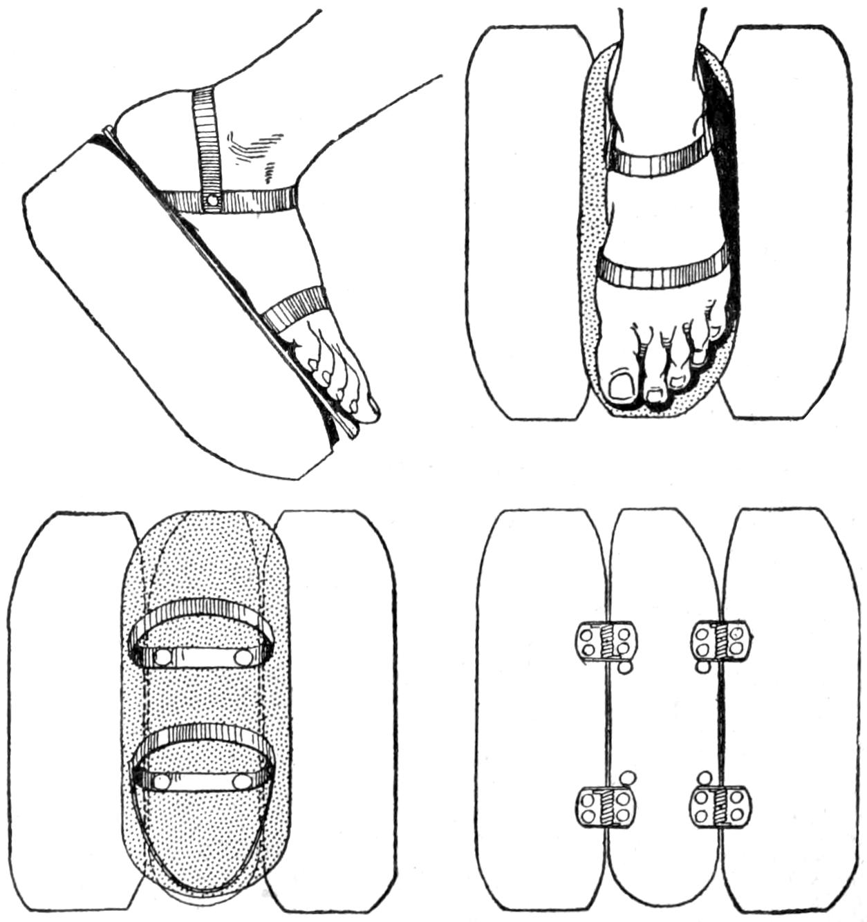
Device for Attaching to the Feet to Work Like Webfeet
When using the device, the upward or forward stroke of the legs will cause the wings to brush against the water, creating sufficient resistance to overcome the slight force of the springs, thereby pushing the wings parallel with the direction of the stroke. During the opposite, or pushing, stroke, the resistance of the water combined with the opening tendency of the hinges will quickly spread the wings out flat, greatly increasing the effectiveness of the feet.—Contributed by J. B. Laplace, New York City.
[382]
In repairing hollow, spun-brass candlesticks I find that frequently the metal rod holding the sections together becomes loosened from the pitch composition designed to hold it in the base. By tinning the outer edges of the sections that fit into the other portions, which are also tinned on the inner surfaces, and then using an iron, or an alcohol torch, to run the solder together at these points, I secure a very firm job. Paper can be placed at points necessary to keep the solder from running out of bounds. When the rod is firm and the nut only gives trouble, solder can be used to fasten the nut permanently to the grease cup at the top.—Contributed by James M. Kane, Doylestown, Pa.
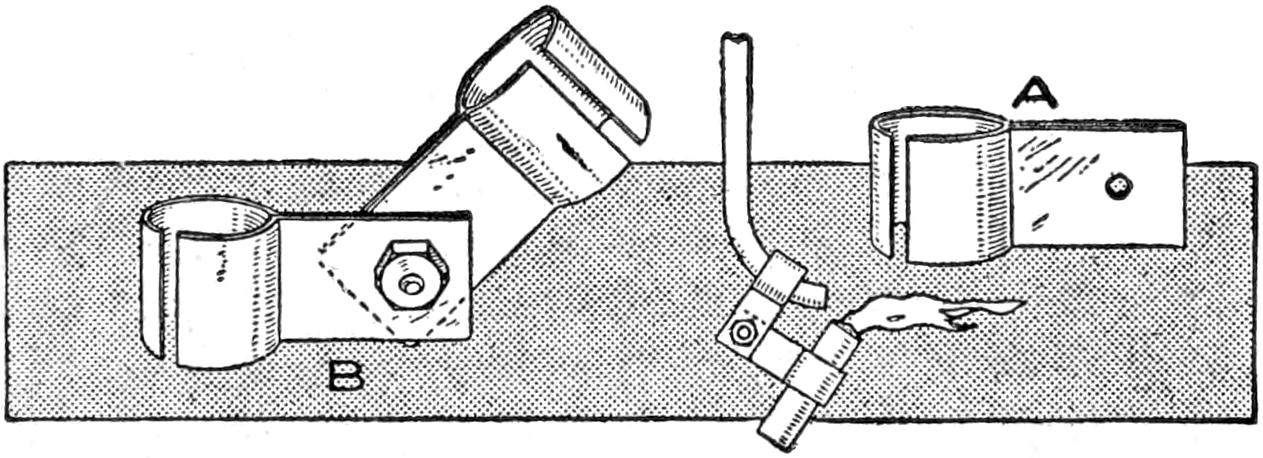
Clamps for Holding the Alcohol Receptacle on the End of the Blowpipe
To solder in close places, I have found the device illustrated quite convenient, as it leaves both hands free to handle the object being soldered. Two pieces of spring brass, about 3 in. long and ¹⁄₄ in. wide, are bent to the shape shown at A and clamped together with a screw taken from a dry cell, as shown at B. This device clamped to the blowpipe end and fitted with a tube, such as used for holding pencil leads, filled with a wick saturated in alcohol, completes the blowtorch. It makes an excellent tool for small work, as the hands are free to hold the parts to be soldered in place.—Contributed by J. A. Tandy, Ghent, Ky.
¶Electric wires should never be run crooked.
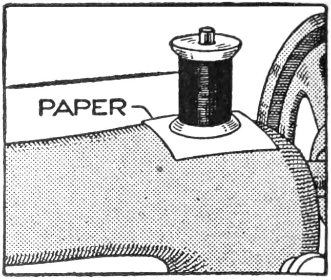
The highly enameled surface of a sewing-machine arm offers so little resistance to the bottom of the spool that the thread will unwind faster than it is used, thereby causing a tangle. A piece of paper slipped over the spool post will cause enough friction to prevent the spool from revolving beyond the proper speed.
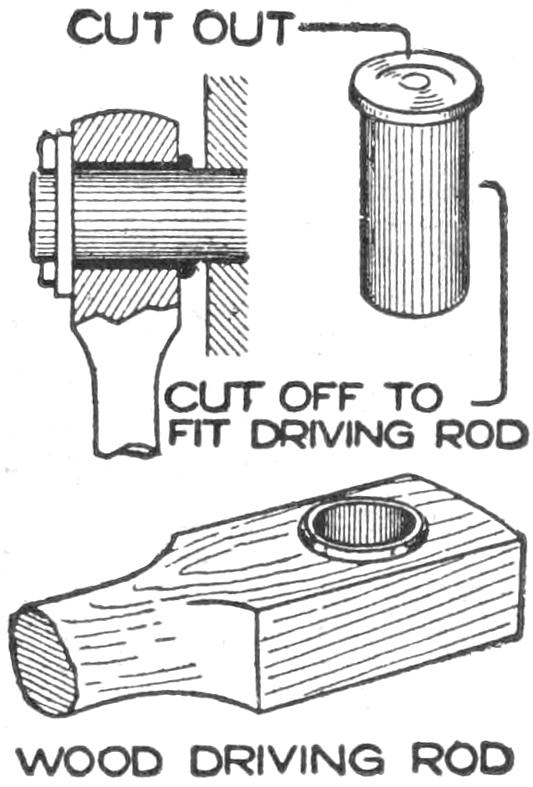
A brass cartridge makes a good bearing to fit in a wood driving rod used to run a small piece of foot-power machinery. It prevents wear on the wood and admits more lubrication than the bare wood. Cut the cartridge to the proper length, and ream out the cap hole even with the diameter of the bore of the shell.
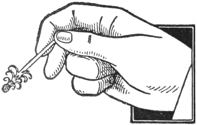
To light a match in a stiff wind is very easy if the wood part back of the prepared end is cut and turned up about it before striking the match. The curled-up shavings about the striker will catch fire easily and hold a flame, where in the ordinary way it is easily blown out when the composition of the striker has burned up.—Contributed by E. K. Marshall, Oak Park, Ill.
[383]

For many years geologists searched for a substance which could be molded into any size and form, and would have the hardness of rock. As a matter of fact it was found that limestone was composed of carbonic-acid gas, clay, and lime, and that when great heat was applied the sealing bond was disrupted and the rock was reduced to a powder. When this powder was placed in water the gas was set free so fast that it made the water boil. The powder, or calcined rock, is now known as lime. This action demonstrated that nature used heat and moisture in forming these materials into rock. Knowing that clay contained silica, and that silica furnished the sealing quality of rocks, experiments were made to reverse the order of this rock formation, and a cement was produced. Equal portions of lime and clay were mixed together and stirred until all parts were thoroughly mingled, and then the mixture was subjected to a very high heat, after which the resulting mass was ground to a powder. When this powder was mixed with water, instead of the gases passing off as they did in the case of the lime, they penetrated the clay and the mixture became hard. This was first called Portland cement, as it was made from Portland limestone.
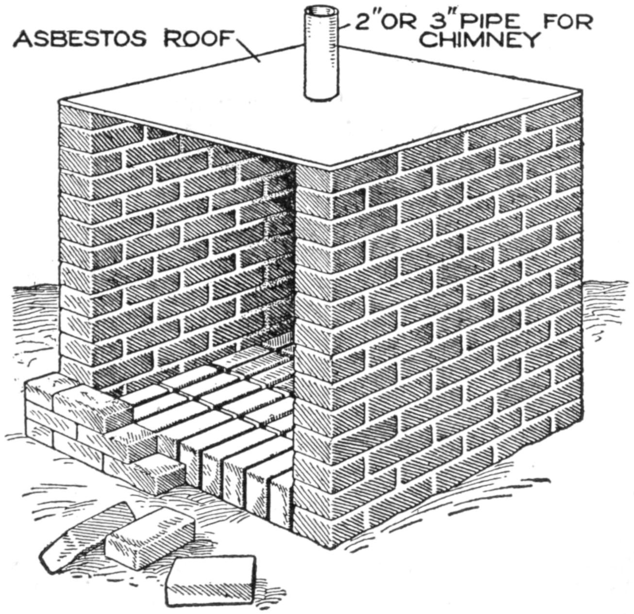
The Furnace is Built Up of Ordinary Brick and Used for Calcining the Lime
This discovery partly solved the problem of artificial-rock making, but not wholly, for the best makes will break, peel, and crack without the slightest cause and when least expected, and besides its dark-gray color and rough appearance is unattractive. Much progress has been made with cement for interior decorations and many of the finest marbles are closely imitated. This grade of cement will not weather and its use is confined wholly to interior work. A white cement is much desired and many of the large manufacturers maintain laboratories where experiments are carried on constantly in the endeavor to produce it.
To build a miniature cement plant, first secure sufficient common brick to make a furnace with an inside cavity, 20 in. square and 24 in. high. Two sides and one back wall are built up, sealing the brick with mortar, clay, or cement. The bottom is covered with bricks standing on edge, and so placed that they will be about ¹⁄₄ in. apart, to serve as a grate. The top is then covered with a piece of tin, or asbestos, and a hole is cut in its center to receive a[384] pipe, about 3 in. in diameter, for a chimney. This chimney should be about 15 in. high. Build the front wall halfway up by laying the brick loosely together so that the fire will get the air through the crevices, then cover the grate with kindling, place coal on top of it, and start the fire. When it is well under way, place a few fair-sized lumps of limestone on top of the fire and complete the wall to the top by laying the brick as closely as possible. Use sufficient coal to burn at least two hours.
When the fire has burned itself out and the furnace has cooled, remove the front wall and take out the burned limestone. Some parts of the limestone will be mixed with the coal, but most of it will remain in the lump, which is known as “black lime,” and when it is placed in water it will give off gas very fast. Obtain some fire clay and thoroughly mix equal portions of lime and clay, then place the mixture in a one-piece pan, made of pressed tin or sheet iron, as a soldered-bottom pan will come apart with the heat. Build up the front of the furnace as before, build a fire and place the pan on the fire and let it burn itself out. When the furnace has cooled, remove the front, take out the pan, and pulverize the mass in the pan. When this powder is placed in water it will become hard. If some sand or gravel is mixed with it, and the mortar thus formed is spread out over a flat surface, a miniature cement sidewalk will be the result.
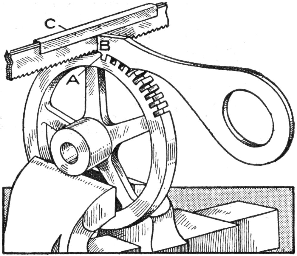
The Gauge Steps Off Each Tooth Accurately for the Saw to Cut the Next Slot
The illustration shows a simple device for making small gear wheels by hand. It is made of a piece of brass, ¹⁄₈ in. thick and about 5 in. long, shaped as shown, forming a tooth, A, according to the size of the teeth required in the gear wheel, with the end B on a radial line from the center of the wheel. Use one or more hacksaws, according to the size of the slots or teeth to be cut. If one blade is not large enough and two are too large, grind off the teeth on the inner side of the saws, or if two are not large enough, place a thin piece of paper or metal between them to make the thickness required. Make a clamp, C, for holding the blades together, by using a piece of sheet brass, 6 in. long and ¹⁄₂ in. wide. This clamp also acts as a depth gauge for the slots.
Place the wheel in a vise and proceed by cutting the first slot very carefully. Place the tooth A of the gauge in this first slot and cut the next by holding the side of the saw close up against the end of the gauge, at B. This keeps all the teeth radiating from the center of the wheel. Cut each slot in the same manner until all of them are formed.—Contributed by George Jupp, New York City.

A Bottle Filled with Water and Tied to a Straight Piece of Wood for a Level
Having need of a level, and there being no place to obtain one within several miles, I constructed one as follows: A long medicine bottle was filled with water and tied to a straight piece of wood, 2 ft. long. After setting it properly by turning the piece end for end several times, I found that it could be used with accuracy.—Contributed by Fred L. King, Islip, L. I.
[385]
The tuberculosis society of a certain locality needed a demonstration cottage for their crusade against the white plague, and they placed their need before the boys of the public-school shops. One class of eighth-grade boys volunteered, and two days after the job was started the complete cottage was delivered to the society. The material required for its construction was as follows:
| 220 | linear feet of ship-lap, 1 in. thick and 6 in. wide. |
| 80 | ft. of 1-in. flooring. |
| 6 | studs, 14 ft. long. |
| 7 | pieces for plates and rafters, 2 by 4 in., 10 ft. long. |
| 3 | pieces for sills, 2 by 4 in., 16 ft. long. |
| 100 | ft. of sheathing boards. |
| 100 | ft. of tar roofing paper. |
The cottage is constructed in sections and can be assembled or dismantled in 30 minutes. The sections are not so heavy but that they can be handled with ease by two men. There are seven sections, namely, the floor, two sides, two ends, and two roof sections. If the cottage is to be moved only a short distance, it can be loaded into an ordinary dray assembled.
Since the building is made in sections, it is well to construct the floor first, which is a simple matter. Cut two sills of the 2 by 4-in. stock, 10 ft. long. Cap these onto the ends of the five joists, which are cut from 2 by 4-in. stock, to a length that will total 8 ft. when the thickness of the two sills are added. Lay the flooring the long way of the section, bringing it flush with all outside edges. This completes the floor section.
The two side sections are made in a similar manner. Cut the studs—12 of them—6 ft. 4 in. long, and four plates, 10 ft. long. Cap the ends of the studs with the floor and rafter plates, according to the measurement on the floor plan. Nail five pieces of ship-lap, cut 10 ft. 1¹⁄₂ in. long, on the bottom of the section, and one similar board to the top edge. Bore four holes, ³⁄₈ in. in diameter, 1 in. from the outside edge in the floor plate. These are for ¹⁄₂-in. lag screws, to hold the parts together when the sections are assembled.
The front-end section is arranged for a 30-in. door. The top, or rafter, plate is cut 7 ft. 4¹⁄₂ in. long. This makes the allowance for the width of the side studs and plates when they are to be assembled, a very important matter to remember. The floor plate is cut 4 ft. 5 in. long. Provide a dummy, made from a waste piece, to be fastened at the bottom of the door studs until the sections are assembled, when it is removed. Use screws to fasten this piece in place. Nail five pieces of ship-lap, 5 ft. long, at the bottom of the section, and an 8-ft. piece at the top. Be careful to set the end studs in from the end of the board the exact thickness of the corresponding studs on the side section.
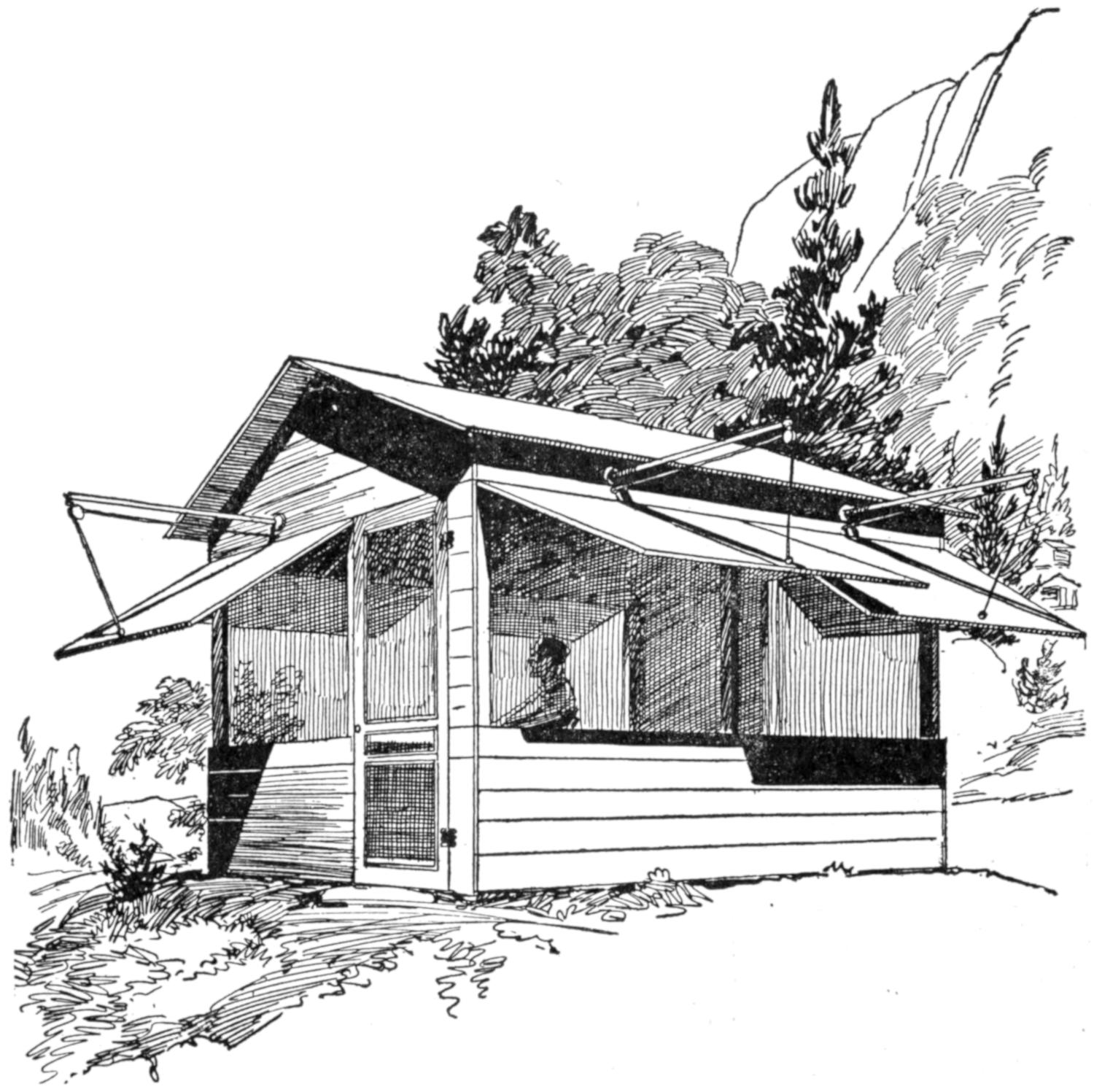
Cottage Built by Boys to Fill the Requirements of a Tuberculosis Society for a Demonstration in Their Crusade against the White Plague
The back-end section is much more easily made. The top plate, as well as the floor plate, is cut the same[386] as on the other section. Place the intermediate stud on the center and nail on ship-lap, as in the other construction.
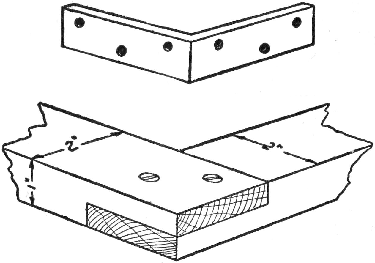
Lap-Joint Corner Construction with Angle-Plate Reinforcement for the Screens or Storm Screens
In making the roof sections, cut four rafters for an 18-in. pitch, or any other pitch desired. These are to be placed at the ends. Note the notch on the lower end of the rafter marked A in the illustration. Make allowance for the thickness of the rider marked C. This piece can be made of 2 by 4-in. stock or any convenient material 1 in. thick. The rider must be nailed to the comb end of the rafters of one section, while a dummy, fastened to the under side of the rafters of the other section, will serve the purpose of holding them true until the roof is placed. Nail the sheathing on, closing the cracks between the boards as well as possible. Start at the comb end and bevel the first board for the comb joint. Make allowance for an 8-in. board at the lower end, so that a 4-in. overhang may be had. Cover these sections with the desired roofing. Place two screw holes at the lower end of each rafter to be used in holding the roof in place. Always use screws instead of nails, if the house is to be dismantled. Provide three rafter locks, marked B, and then the roof is ready for assembling.
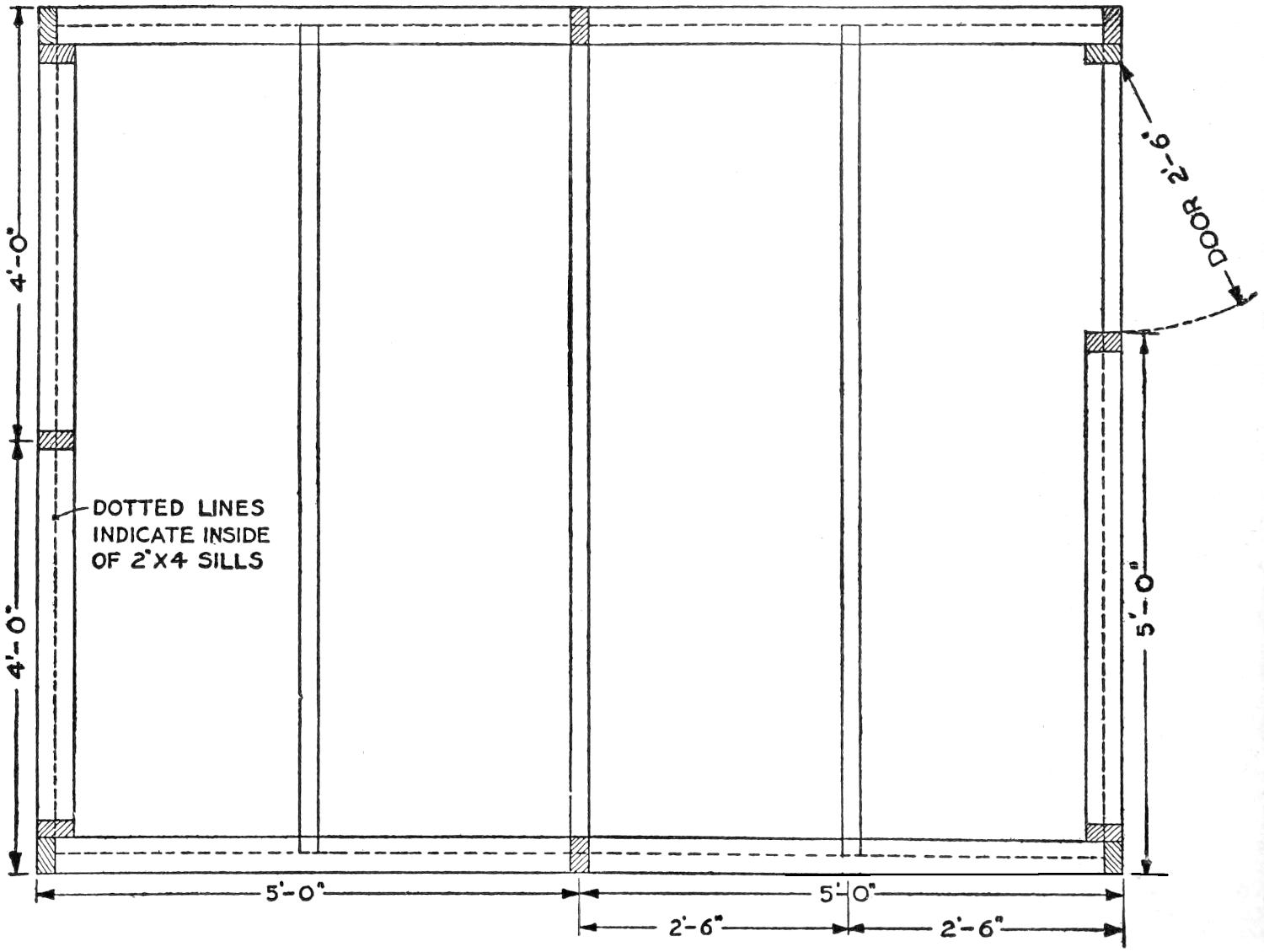
The Floor Section Consists of Simple Frame Construction of Ordinary Material and Flooring Boards Fastened on the Frame to Make the Edges Flush with the Sides and Ends
The three gable boards, cut from ship-lap, can be more easily made after the cottage is assembled. After they are fitted, each board must be fastened[387] with screws which will find a hold in the rafters. These boards are marked D. Be sure that all lag-screw holes for the corner and floor moorings are bored before starting to assemble the parts.
The screens are made with the half-lap construction at the corners reinforced with angle plates. This construction is shown in the detail sketch. The screens, or storm wings, should be covered with a good grade of oilcloth or canvas. They are hung with an ordinary 3-in. wing hinge.
The adjusting device for these storm wings consists of a piece of 1-in. gas pipe, 4 ft. long, threaded on one end to receive a collar. Two flanges are used, one on each side of the board, above the wings and located centrally. A wood plug is driven into the outer end of the pipe, and a small pulley, suitable for a ³⁄₈-in. rope, hung on it. Place a screw eye centrally into the lower edge of the wing and tie the end of a ³⁄₈-in. rope to it. Run the other end of the rope through the pulley and a hole in the wall. Place screw eyes, to which the rope may be tied, at proper places on the inside of the wall boards. An ordinary screen door is hung in the door opening.
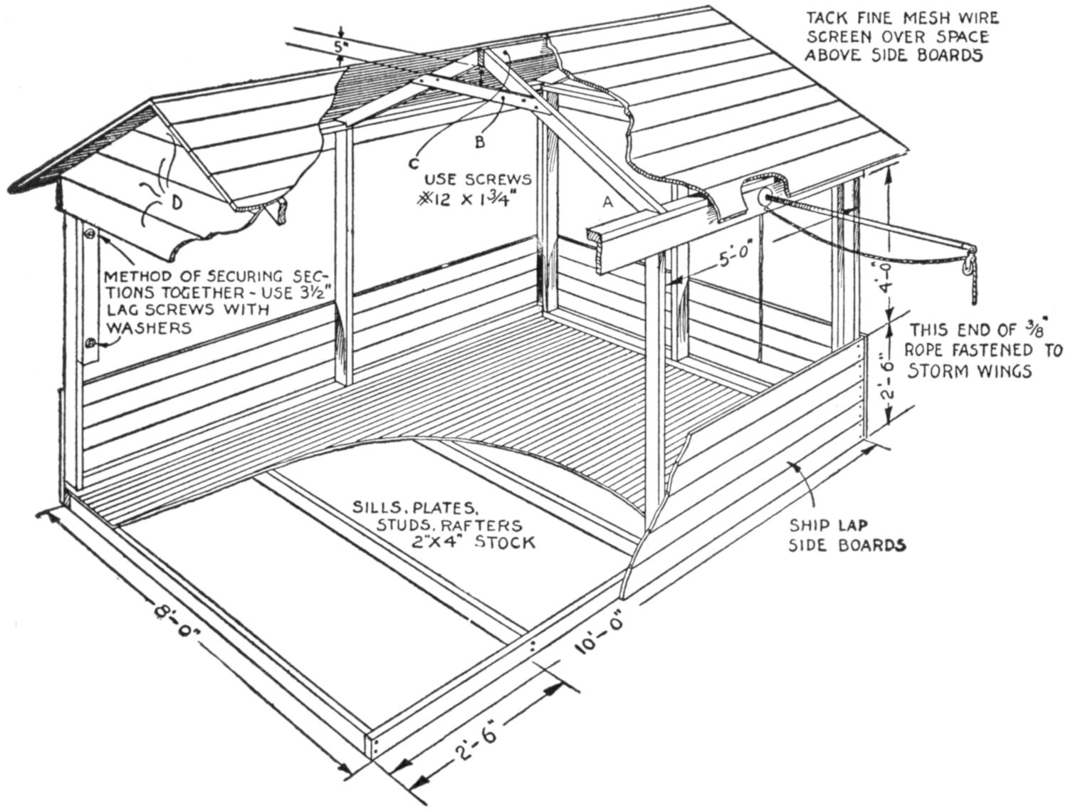
Each Section is So Constructed That It can be Easily Handled and Set Up with the Others to Form a Cottage, Only Screws being Used to Fasten the Joints for Quick Assembling
A house built in this manner was placed in the courthouse lawn as a permanent fixture. Among other things brought out in the construction was the fact that a cottage may be built by a boy at a cost less than $50. Thus a stricken parent, brother, or sister may be provided, by the hands of a young mechanic, with the first means that may bring him or her back to health.
Putty purchased from a dealer is usually in a soft and oily state, and the amateur glazier soon finds his hands, as well as the tools, plentifully smeared after the job is finished. Removing this from the hands with the putty knife or a stick is very tedious, but if a bunch of fine excelsior is used, the putty will be removed quickly and thoroughly.
[388]
It is often very difficult when focusing an enlarging camera to determine just when the perfect focus is reached, especially when the negative is dim and without contrasting lights and shades. This difficulty may be overcome and a perfect focus quickly determined by the use of a focusing screen prepared as follows: Take a clear film or plate, one that has been fixed without being exposed, and when dry, rule lines on it with India ink to form small squares. To make the ink adhere to the film, dust the latter with talcum powder.
To use the screen, slide the film to be enlarged in place and set it for the size of enlargement, focusing roughly. Remove the film or plate and put the screen in its place. The camera may now be brought to a perfect focus with ease, as the black lines show up sharp and clear on the screen. When the focus has been determined the screen is removed and the film replaced.
The squares may be drawn from ¹⁄₄-in. size down to the smallest it is possible to make. For large views it is easier to focus with the smaller squares. If the squares are made to a certain size they can be measured when thrown on the screen and the degree of enlargement determined.—Contributed by R. H. Galbreath, Denver, Colorado.
¶The longitudinal carriage handle should never be held in the hand when cutting threads.
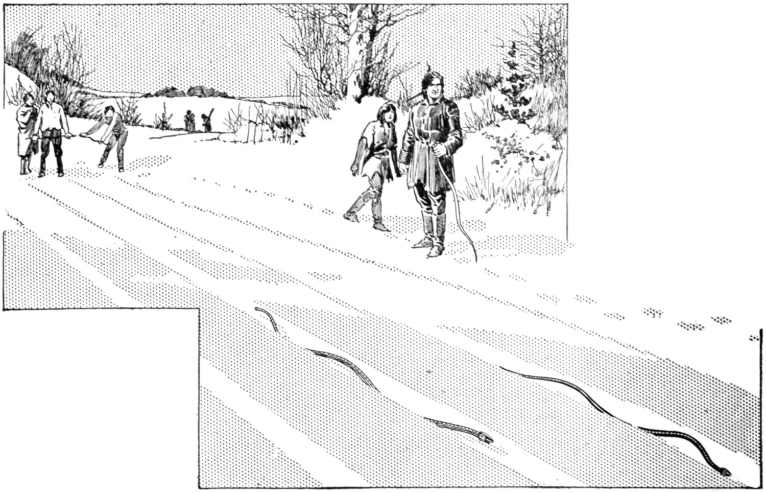
Throwing the Snow Snake in Tracks Made through the Snow with a Log: Each Player Tries to Get His Snake First Out at the End of the Track More Times Than His Opponents
Ask any Canadian Indian what a snow snake is, and he will tell you that it is a piece of twisted wood, such as a wild grape vine, about 5 or 6 ft. long, and 1 in. or over in thickness, stripped of its bark and polished. It is grasped with one hand in the center and given a strong forward throw at the tail end by the other hand, while at the same time the hold in the center is loosened. With a hard bottom and about 1 in., or more, of light snow on top—ideal conditions for playing the game—the Indian snake will travel for a long distance when thrown by an expert, and to a novice seeing the snake traveling along at a rapid speed, raising and lowering[389] its head as the wood vibrates from side to side, its resemblance to the real reptile is perfect.
When the Indians have tests of skill with the snake they make tracks through the snow by drawing a log in it, and sometimes as many as a dozen tracks are made side by side, and a dozen snakes are sent along at once. The one who makes his snake emerge from the end of the track first the most times out of a certain number of throws, takes the prize. The trick of throwing the snake is not at all hard to acquire, and it makes an exciting game.—J. E. Noble, Toronto, Can.
When working with wood to be made into furniture, or other constructions of a high grade of workmanship, the ends of the finished pieces should be shellacked in order to prevent moisture from entering the ends. The ends are more susceptible to moisture, as the pores of the wood are exposed. The application of this remedy will often prevent warping or winding of boards, which is particularly distressing after a piece has been shaped to its final size.
The pieces should be stored in a warm, dry room, and in any event care should be taken that they are exposed evenly. If a board is placed on the top of a pile of similar pieces, it will be noted that, if left overnight and the weather becomes rainy, the upper piece will be warped. This is caused by the absorption of moisture on the upper side, the resulting expansion forcing the piece to warp or curve.
Long pieces of wood under process should be set on end while being stored temporarily. The permanent storage should be in racks having supports about 2 ft. apart. If the supports are too far apart, the boards may warp or wind at intervening points. Boards in piles should be separated by strips about 1 in. thick, set about 3 ft. apart, in order that the lumber may be open to the air. This will keep the stock more uniformly dry.
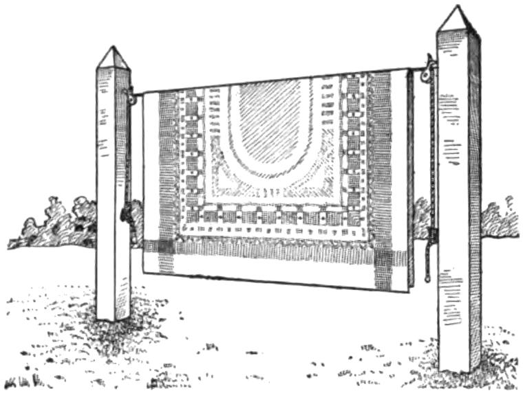
When the Rug is Placed on the Line It is Easily Raised by Pulling the Rope Ends
An easy way to put a heavy carpet, or rug, over a clothesline is to fasten two pulleys, one to the house and the other to a post or tree, or on two posts, and hang the line between them; then pull the rug over the line and draw up the ends of the line. A very heavy rug can be easily hung in this manner. The line should be long enough to reach over the pulleys and to the ground and have end enough at both supports for fastening.
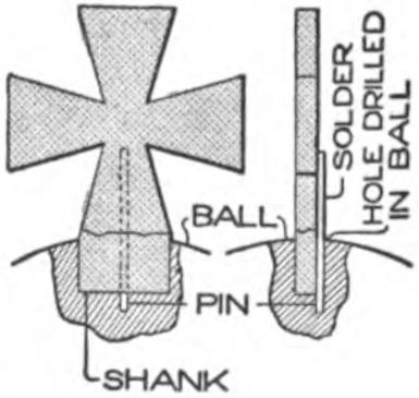
A metal cross, the shank of which was imbedded in a plaster ball, broke off level with the top. Not wishing to remove some of the plaster to take out the shank, I soldered a stout brass pin on the back of the cross, allowing the pin to project far enough to fit solidly into a small hole back of the shank. This allowed the cracked edges to fit closely together so that the crack could be entirely concealed with a touch of bronze paint.—Contributed by James M. Kane, Doylestown, Pa.
[390]
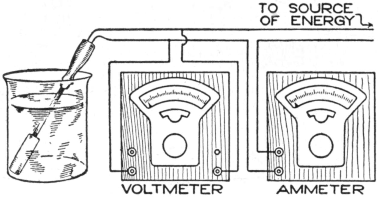
Connections to the Voltmeter and Ammeter for Measuring the Input to an Electric Heater
The efficiency of any machine is defined as being the ratio of the output to the input expressed as a percentage, and both quantities must be measured in the same units. For example, the output of a motor is 10 hp. when the power taken by the motor from the electric circuit to which it is connected is 9,325 watts. What is the efficiency? Since the output must be expressed in the same units it is necessary to change the 10 horsepower to watts or the 9,325 watts to horsepower. There are 746 watts in each horsepower. The 9,325 watts are equivalent to 9,325 ÷ 746 or 12.5 hp. The efficiency is then equal to 10 ÷ 12.5 or .8; that is, the output is .8 of the input or, when multiplied by 100 to change it to percentage, 80 percent.
By way of an example, consider the efficiency of an electric heater, like the one shown in the illustration, which is immersed in water placed in a suitable vessel. The energy input to this heater in a given time may be easily determined by measuring the current passing through the heater circuit and the difference in pressure between the terminals of the heater. These measurements may be made, in case the heater is operated on a direct circuit, by means of any ammeter and voltmeter of suitable capacity, connected as shown. If the heater is operated on an alternating-current circuit, only alternating-current instruments can be used, as certain types of instruments will not operate when connected to such a circuit. In either case, the product of the ammeter reading in amperes and the voltmeter reading in volts will give the power taken by the heater in watts, assuming the heater winding to be noninductive. If the heater winding is not noninductive, then the current and the electrical pressure will no longer be in phase when the device is operating on an alternating-current circuit, and a wattmeter must be used. Practically all heating elements are wound noninductively so that the power may be measured by means of an ammeter and voltmeter.
The energy taken by a heater in a given time will be equal to the product of the average power and the time. For example, if the heater takes 300 watts for 30 minutes—¹⁄₂ hour—then the energy consumed is equal to 300 times ¹⁄₂ or 150 watt-hours, which is equal to .15 kilowatt-hour.
To determine the output of the heater is a little more difficult, but it may be approximated as follows: Since the object of the device is to convert electrical energy into heat energy the output must be measured in heat units. The unit of heat most commonly employed is the calorie, which is the heat required to raise the temperature of one gram of water one degree centigrade. Hence, if a certain weight of water has its temperature increased a definite number of degrees centigrade by the electric heater, then the total heat imparted to the water in calories will equal the weight of the water in grams multiplied by the change in temperature in degrees centigrade. Of course, the heat generated by the heater exceeds that obtained by the above calculation, due to the fact that some heat is imparted to the vessel containing the water and to the supports for the vessel, but it is only the heat imparted to the water that must be considered, as the other heat is not useful.
When the temperature of the water is raised to the boiling point and a part of the water is evaporated, the foregoing method of calculating the heat imparted to the water no longer holds good, and the following method must be used. Weigh the water before and[391] immediately after the test to determine the amount of evaporation. For each gram of water evaporated there will be required approximately 536 calories, and the heat in calories imparted to the water to raise its temperature to the boiling point will be equal to the difference between 100 and the initial temperature of the water multiplied by the weight of the water at the start. To determine the efficiency, the input to the heating element in electrical units must be changed to heat units which may be done by multiplying the power in watts by the time in seconds and this product in turn by .24, giving the result in calories. The following example may serve as a help in performing such an experiment or test.
| Weight of water at the start | 500 | .0 | grams. |
| Weight of water at the end of test | 474 | .5 | grams. |
| Temperature of water at the start | 25 | deg. C. | |
| Average current taken by the heater | 6 | .5 | amperes. |
| Average pressure at the heater terminals | 110 | volts. | |
| Time heater is connected | 5 | ¹⁄₂ | minutes. |
| Change in temperature of the water | 75 | deg. C. | |
| Heat developed in heater: 6.5 × 110 × 5¹⁄₂ × 60 × .24 = | 56,628 | calories. | |
| Heat absorbed by water in coming to boiling point: 500 × 75 = | 37,500 | calories. | |
| Heat used in evaporating 25.5 grams of water: 536 × 25.5 = | 13,668 | calories. | |
| Total heat absorbed by water | 51,168 | calories. | |
| Efficiency of heater: 51,16856,628 × 100 = | 90 | .4 | per cent. |
This value of efficiency may be increased by insulating the vessel with a nonconductor of heat and providing a covering for it, thus decreasing the losses to the air and surrounding objects.
The efficiency of an electric stove or electric iron, or, in fact, any electrically heated device, may be determined in a manner similar to the water heater. In the case of a stove, place a vessel filled with water on it and measure the heat imparted to the water in a given time, also the input to the heating element in the same time, from which data the efficiency may be calculated. In the case of an electric iron, dampened cloths may be ironed and the actual water evaporated by the iron, determined by weighing the cloths before and after the ironing, together with the increase in weight of the cloth on the ironing board, the time the iron is in use and the temperature of the cloths. The actual water evaporated is the difference in the weight of the cloths before and after ironing, minus the increase in weight of the cloth on the ironing board, which takes up some of the moisture from the cloths being ironed.
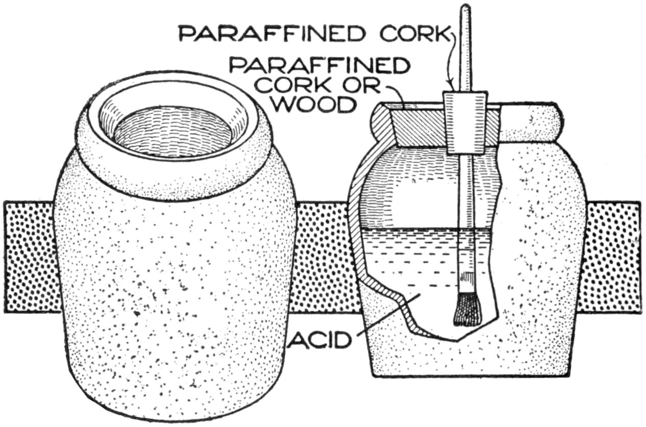
A Bottle Made from an Earthen Mustard Pot to Contain Acid
A small earthen mustard pot of the type shown makes an ideal acid pot for the bench, as it is not only acid-proof but will not upset so easily as the ordinary acid bottle. The large cork, or stopper of soft wood, thoroughly boiled in hot paraffin, is bored for the insertion of another paraffined cork holding the acid-brush handle. If a coat of paraffin is given the handle, it will easily resist the action of the acid and last much longer.
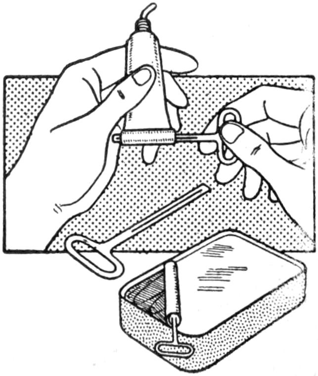
Tubes of paste, glue, etc., may be more easily handled by applying an ordinary key, such as found on most cans containing fish put up in oil. The end of the tube is inserted in the slot of the key and then turned.—Contributed by J. H. Priestly, Lawrence, Mass.
[392]
It will almost appear impossible to those unfamiliar with laboratory methods that one may watch the vibrations—3,600 per minute—of an alternating current in a little pocket mirror without the use of any apparatus other than a telephone receiver. The experiment is very interesting and instructive, one that may be performed at practically no expense.
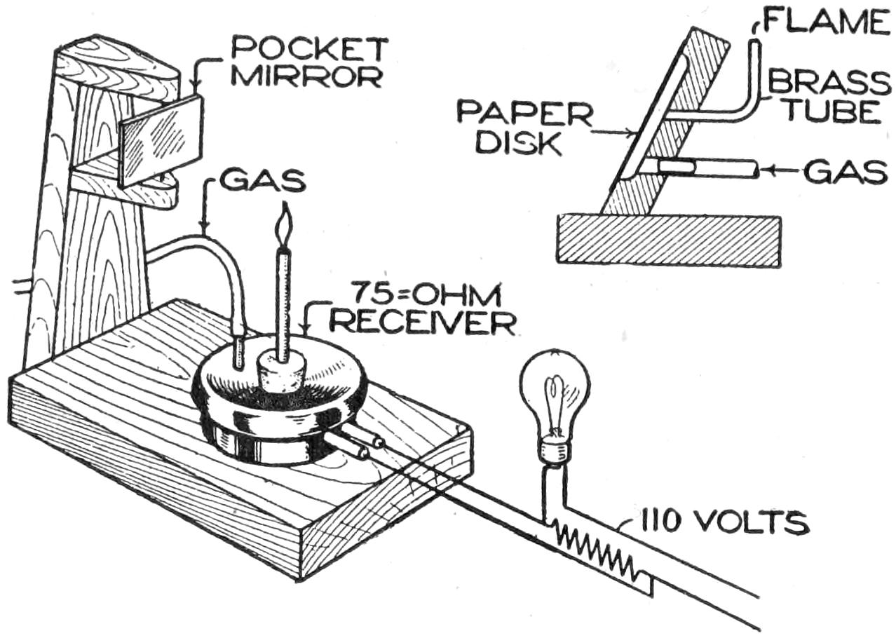
The Alternations of the Current may be Seen by Looking in the Mirror
Take an ordinary inexpensive watchcase receiver, drill a hole in the cover for a short piece of brass tubing, to make a gas connection, and then plug up the center opening with a cork, into which is tightly fitted a piece of ¹⁄₈-in. tubing. The upper end of this should be closed with a plug having a central opening about the size of a pin. Procure a small rectangular pocket mirror and remove the celluloid covering, and then, across the back, solder a piece of straight wire to form a vertical spindle, about which the mirror may be rotated. Connect any resistance, such as a magnet coil of 10 or 20 ohms, in series with an incandescent lamp, and then connect the receiver terminals to the ends of this resistance. In this manner an ideal alternating-current supply of a few volts to operate the receiver safely is secured. Turn on the gas only sufficient to produce a narrow pencil of flame, not over 1 in. long. Mount the mirror as shown, or hold the spindle between the thumb and forefinger of the left hand while rocking it back and forth with the right. Ordinarily only a streak of light will appear, but immediately upon turning on the current this streak will be broken up into a series of regular waves, flatter or sharper according to the speed with which the mirror is rocked. After carefully noting the wave form, connect the receiver with the primary of an ordinary medical coil, across the make-and-break, and note the marked difference in the waves.
By replacing the receiver with a block of wood having a circular depression, about 2 in. in diameter and ¹⁄₈ in deep, over which is pasted a disk of smooth paper, the waves set up by the human voice may be observed if the talking is done loudly and close to the disk. The gas connection in this case is made from the back of the block, as shown. As the several vowels are sounded, the characteristic wave from each will be seen in the mirror. It is also interesting to increase the pitch of the voice and note how much finer the waves become.
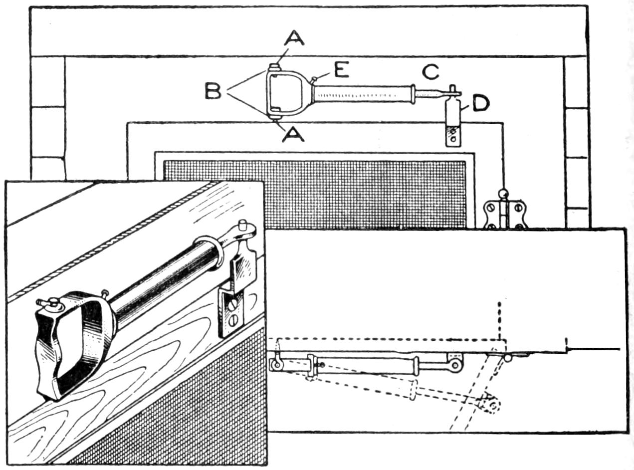
Air-Cushion Check Made of a Bicycle Foot Pump for a Screen Door
An outside screen door causes considerable annoyance by slamming when exposed to the wind, even if it is equipped with a bumper. Nothing short of a door check will prevent this slamming, so I made a very simple[393] pneumatic check for our door, which works entirely satisfactorily.
A discarded bicycle foot pump was procured and hinged to the casing over the door, as shown in the illustration. The hinge was made as follows: Two holes, A, were drilled through the stirrup, as near the foot plate as possible; two ordinary screw eyes were turned into the door casing at B, and two pins were passed through the holes in the screw eyes and the holes in the stirrup. This allows the pump to swing when the door is opened. The end of the plunger rod C is flattened and a hole drilled through it to receive the pin at the top of the bracket D, which is screwed firmly to the door.
The action of the pump when the door is opened can be readily understood. The check is adjusted very easily by the machine screw E, which controls the exhaust of the air when the door closes. The screw is turned into the hole in the base of the pump where the pipe was originally connected. One side of the end of the screw is slightly flattened to allow a better adjustment. The pump can be quickly removed by pulling out the upper pin in the hinge part.—Contributed by M. C. Woodward, San Diego, California.
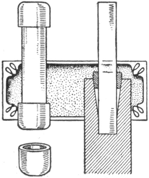
In order to fasten a short piece of tubing in a socket which had become worn to a funnel shape, without having to tap the socket and put in a threaded bushing, it was fixed as follows: One of the brass tips on a spent cartridge fuse was cut off and one of its ends filed tapering. After trimming the fiber lining so that it would fit snugly over the tube, it was driven home. The combination of brass and fiber adjusted itself nicely to the shape of the worn socket and made a tight fit.
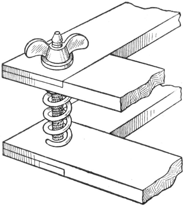
When putting a tennis racket in a press, it is difficult to keep the press open to let the racket slip in. This can be easily remedied by simply putting a small coil spring around each of the four bolts, as shown. This will always open the press when the bolts are loosened.—Contributed by W. X. Brodnax, Jr., Bethlehem, Pa.
At outdoor carnivals and fairs there is usually a fortune teller who uses a glass wand to cause one’s fortune to appear on a pad of paper. Anyone may perform this trick by observing the following directions.
Instead of a glass wand use a long, narrow bottle of glass. Dip a new pen into copper sulphate, diluted with six parts of water, and write out the “fortune” on a piece of paper. The writing, when dry, will not be visible. Next procure two corks to fit the bottle. An unprepared cork is placed in the bottle and the other is pocketed, after hollowing it out and inserting a small sponge soaked in pure ammonia.
The bottle with the cork is passed out for examination. The cork is casually placed into the pocket after it is returned by a bystander. A pad of paper is then proffered and an initial is placed on the pad of paper by the person whose “fortune” is to be told. The paper is rolled up, with the prepared side on the inside, and inserted into the glass bottle. The fumes of ammonia will develop the mysterious message. The trick can be repeated if several prepared sheets of paper are on hand, and always proves of interest in a party of young persons.
[394]
Models made as a pastime or for exhibition purposes should represent correctly the full-sized machine, not only as regards general design but also in the proportioning of parts, the finish, and the choice of materials. The satisfaction derived from the possession of a model is greater when it is truly representative. Study and careful measurement of the original are necessary to attain this result, and provide valuable experience in the application of correct mechanical principles.
The most conspicuous, though perhaps not the most frequent, errors made by amateurs are in the proportioning of the various parts. This usually arises from insufficient study of the original machine, and is often sufficiently glaring to attract the attention even of a casual observer. The foundation or base of a model stationary engine, for example, is often painted to resemble brickwork. This is correct, provided the spaces are proportioned so as to represent bricks and not three-ton slabs of granite.
Mistakes are made in the selection of pulley wheels, both as regards the character and the size of the pulley that would be suitable for the particular purpose.
The “cheese-head” or flat-head machine screw appears to have a peculiar fascination for the model maker, judging from the frequency with which it is misplaced. It is only necessary to consider what would happen in a full-sized machine if such screws were used for making joints in valve rods, cylinder covers, slide bars, for fixing bearing caps, and the like, to realize how completely such a defect mars the appearance of a model to a discriminating eye. Bolts, or, in some cases, studs and nuts, should be used to give an appearance of correct workmanship.
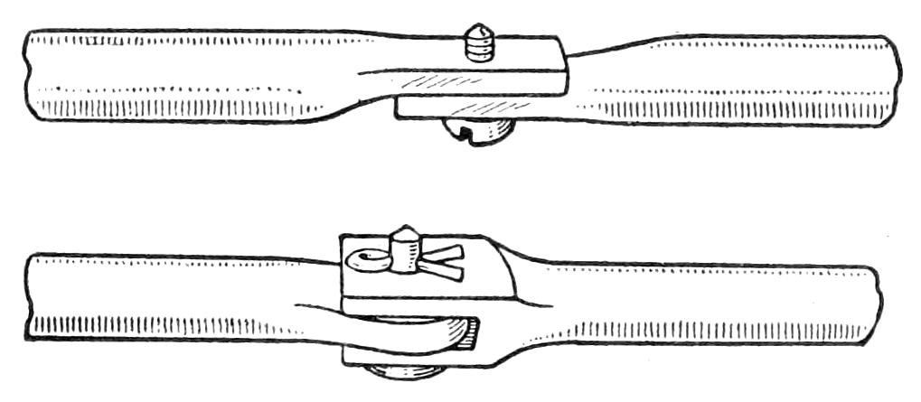
Fig. 1

Fig. 3
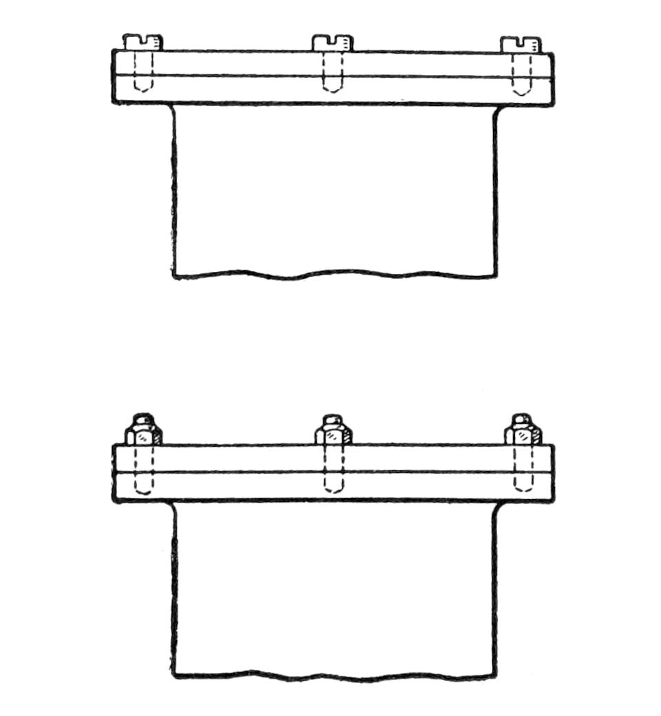
Fig. 2
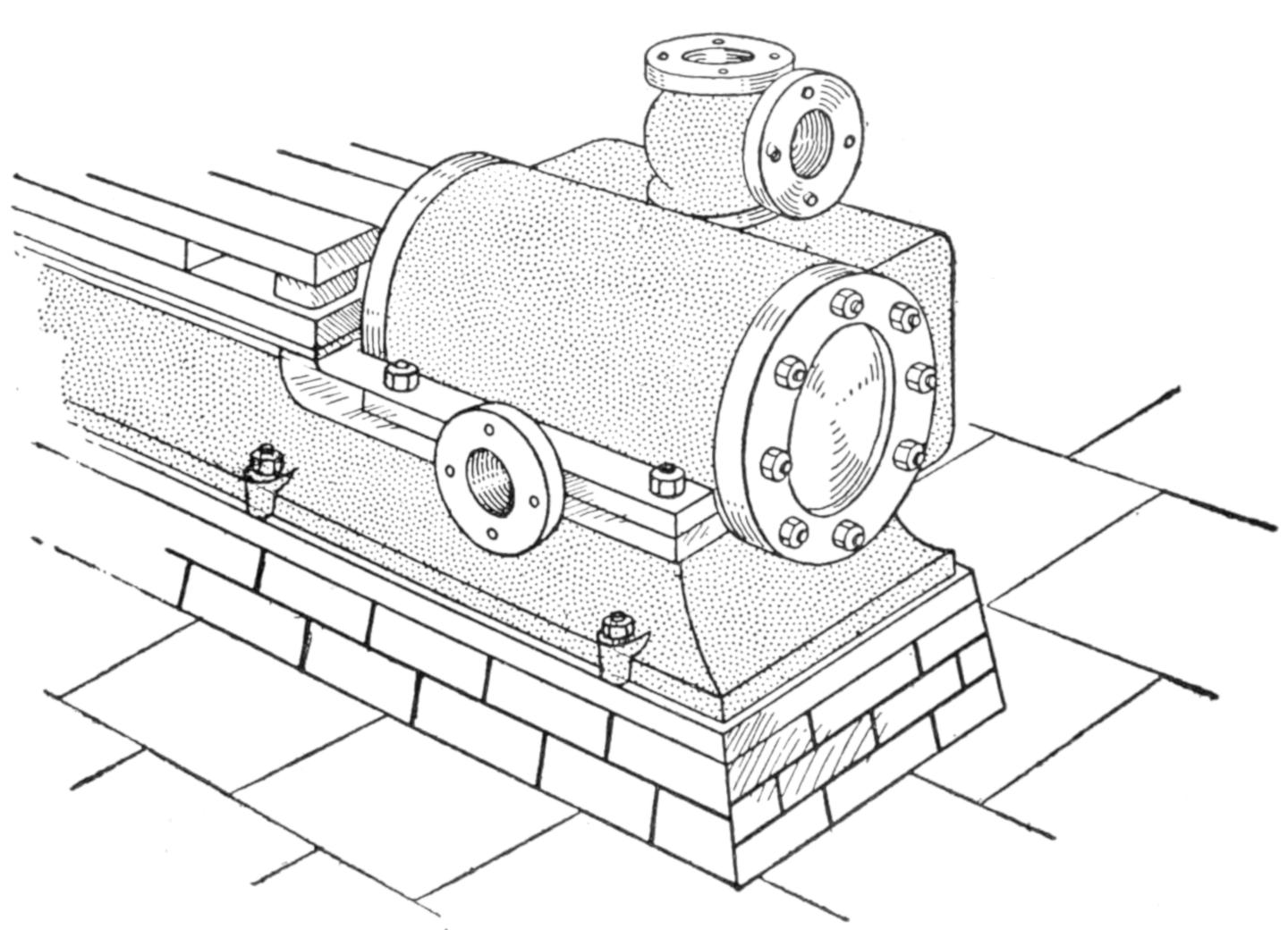
Fig. 4
Details of Correct and Incorrect Practice in Model Making: Fig. 1, Valve Rod Joined by “Cheese-Head” Screws, Wrong, and Joined by Joint and Pin; Fig. 2, Bearing Cap Fixed with Flat-Head Machine Screws, Wrong, and with Studs and Nuts; Fig. 3, Cylinder Cover Fixed with Flat-Head Machine Screws, Wrong, and with Studs and Nuts; Fig. 4, Representation of a Brick Foundation, Incorrectly on Side, and Correctly on End
Many novices make a serious mistake in the character of the finish given to the various parts. This usually results through devoting insufficient attention to the method of manufacture adopted in engineering practice. Under the impression that a mottled appearance gives an ornamental effect, they will make a shaft end with a[395] scraped finish. To the casual observer there would be nothing amiss, but a mistake of this kind would offend the trained eye of an engineer, because it is entirely unrepresentative. The object of scraping sliding surfaces is to obtain a greater degree of flatness by removing small inequalities. As the subsequent use of a file would only undo the work of a scraper, the surface is permitted to remain mottled, as left by the scraping tool. But the end of an engine shaft is not a sliding surface, and in engineering practice would be finished in a lathe.
Nickelplating is often resorted to in order to produce a brilliant and supposedly pleasing finish to the model of a casting. This is obviously wrong, for the actual casting—which might weigh tons—would be painted, and not electroplated.
Locomotive wheels or stacks of polished brass add to the appearance of a model only in the eyes of the uninitiated. Few persons would care to risk a railroad journey if the engine had brass wheels. Iron or steel is the correct material to use. Brass is also often used instead of iron for cylinders, connecting rods, and starting levers on models, or for steam pipes, which should be made of steel or copper.
In certain cases there may be unusual difficulties in using the correct material for a machine part made to a small scale. It is then permissible to use other material, provided some attempt is made to disguise the fact by means of an appropriate finish. Copperplating, for example, may be used to disguise some other material, if the parts should properly be made of copper. It is often convenient to make a model boiler of brass. It should not be polished but bronzed, to represent the iron or steel plates of a full-size boiler.
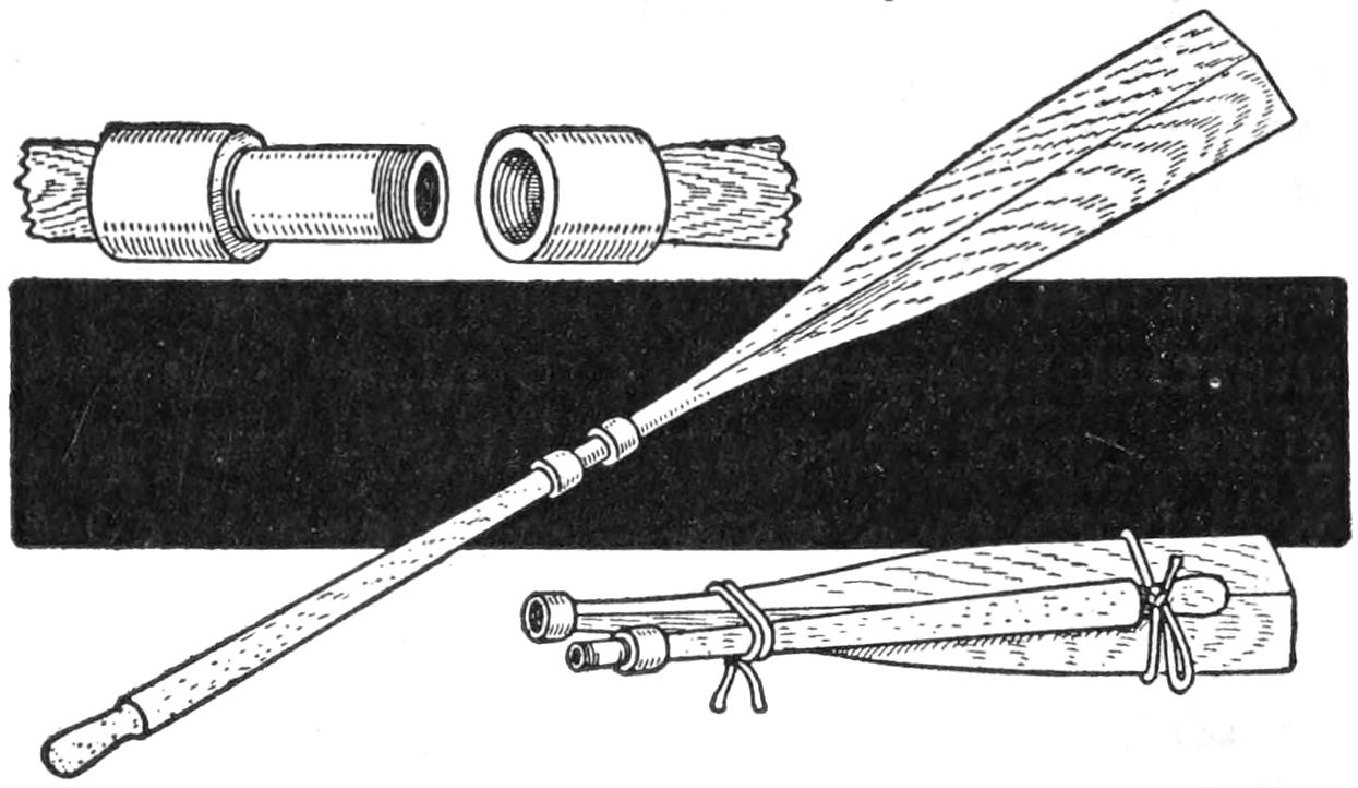
When Knocked down the Oars Occupy Small Space in a Boat
Owners of sail or power boats will find the take-down oars shown in the sketch easily made and of value in an emergency far out of proportion to the space occupied in a boat. A pair of ordinary oars was cut as shown, and pipe fittings were attached to the ends to form a detachable joint. When knocked down the oars may be stored in a seat cupboard, or other convenient place.—Contributed by H. E. Ward, Kent, Wash.
Requiring a number of propeller blades for use in making models of windmills, and other constructions, I found that I could save much time and obtain a satisfactory set of propeller blades by using ordinary shoehorns of the same size. The small ends of the horns were flattened out so that they could be fastened to pieces of wood for bearings, and then hammered to the proper shape for cutting the air, or receiving the force of the wind.
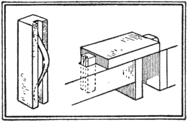
Serviceable bench stops may be made by grooving pieces of maple, or other close-grained, hard wood and fitting strips of clock spring into them, as shown in the sketch. The pieces must fit the holes in the bench top snugly, and the spring will then prevent them from slipping out. The end of the spring fastened to the stop should be annealed so that a hole for the screw may be drilled into it readily.—Contributed by Stanley Mythaler, Spring Valley, Minn.
[396]
To make a good putty the following formula should be used: Mix equal parts of firmly ground whiting and white lead with enough linseed oil to make a thick liquid; add enough commercial putty to this to make the consistency of regular putty. This putty will not crack or crumble, and it costs very little to make. If desired, the commercial putty may be left out and enough whiting added to take up the liquid. The life of this putty is four times greater than a commercial putty.—Contributed by L. E. Fetter, Portsmouth, N. H.
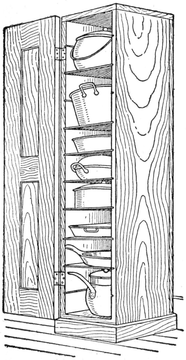
The illustration shows a style of a cupboard in which kitchen utensils can be kept in an orderly manner without taking up a great deal of space. The cupboard is tall and narrow, and the interior face of each side is scored at even intervals with saw cuts, ¹⁄₄ in. deep. In the grooves are placed shelves, which are merely squares of galvanized iron. By placing the shelf in the proper grooves the space is adapted to the size of the utensil. The small floor space occupied allows the cupboard to be placed in the part of the kitchen that is most convenient.
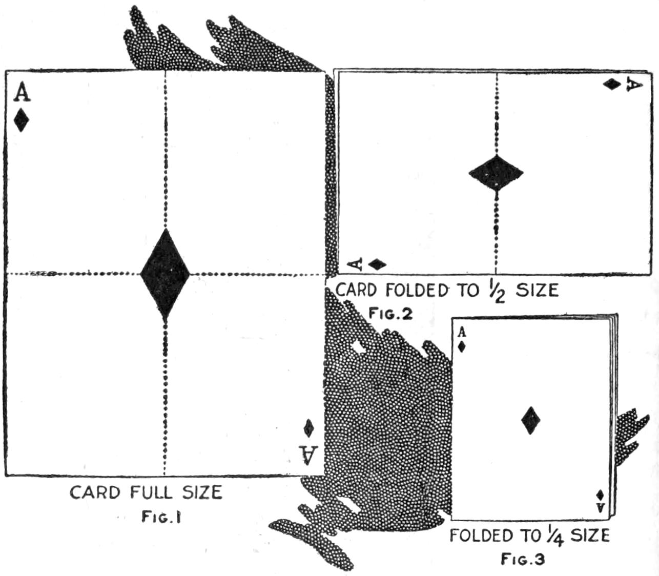
Fig. 2
Fig. 1
Fig. 3
Reducing the Size of a Playing Card While Holding It in One Hand
A clever diminishing card trick may be played with a piece of paper made up as shown in the illustration. Show the audience the whole card, Fig. 1, then fold it halfway and show again, Fig. 2, then again, Fig. 3. If this is done quickly it will not be noticed. A piece of paper is used the size of a regular playing card, and an ace is made on one side. When it is folded over one side of the reduced size is made to show the same ace, then another fold is made and the smaller ace is made.—Contributed by Louis Waherer, Tiffin, Ohio.
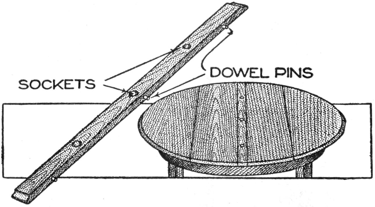
The Extra and Narrow Table Leaf Carries the Electric Sockets for the Cooking Apparatus
The usual method of running a wire from a chandelier or wall bracket to a heating device on the dining-room table is inconvenient as well as unsightly. This I overcome by making a special narrow leaf to put in the extension top into which sockets are set flush for extension wires. These are connected to a floor socket, or a line can be run under the carpet or rug.—Contributed by Maurice Baudier, New Orleans, La.
[397]
A quick-drying dressing for fishlines may be prepared as follows: Mix equal parts of boiled linseed oil and gold sizing; apply this to the line in a moderately thick coat. Dressing which will not dry as rapidly but which will resist the water as well is made by melting together 4 parts of paraffin and 1 part of resin. Melt the paraffin in a deep metal vessel over a small fire, and add the resin after the paraffin has dissolved. Care must be taken not to permit the fire to come into contact with the mixture. Allow it to cool slightly and then coil the line in the vessel. Draw it through a piece of wet sponge held between the fingers. This will cool the mixture rapidly and the line may then be stretched and polished with a wet rag.—Contributed by A. E. Tetu, Ottawa, Canada.
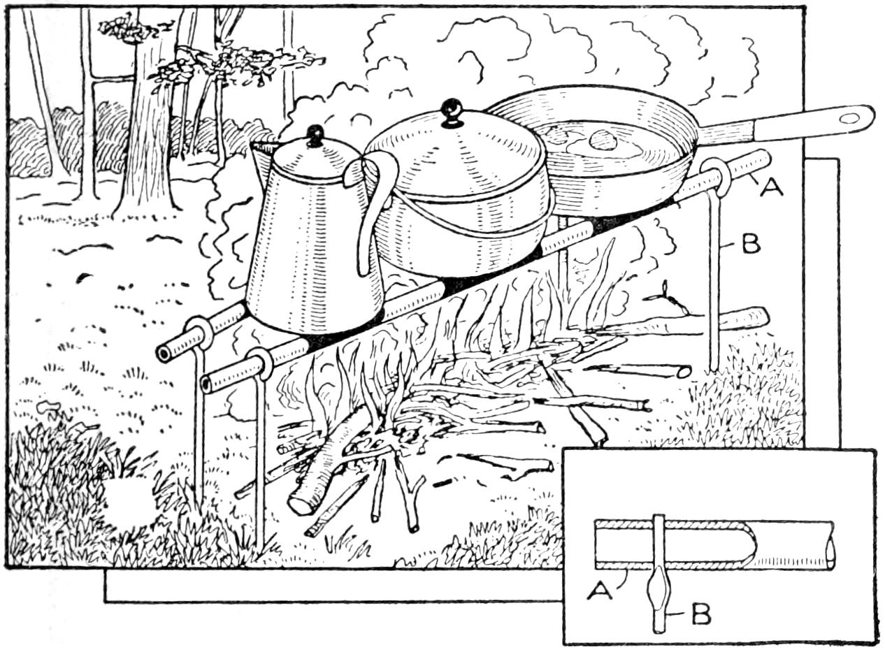
Iron Pipes Held by Pointed Steel Rods Provide a Simple and Satisfactory Support for Cooking Utensils in the Camp
A compact, simple device for holding cooking utensils over a camp fire is shown in the sketch. It may be collapsed into a small bundle and is of light weight, factors which are important in camping equipment. The device consists of two sections of pipe, A, supported on rods, B, having eyes bent at their upper ends. The lower end of the supports is pointed and may be driven into the ground so as to spread the pipes more at one end than at the other, thus providing for large as well as small utensils.
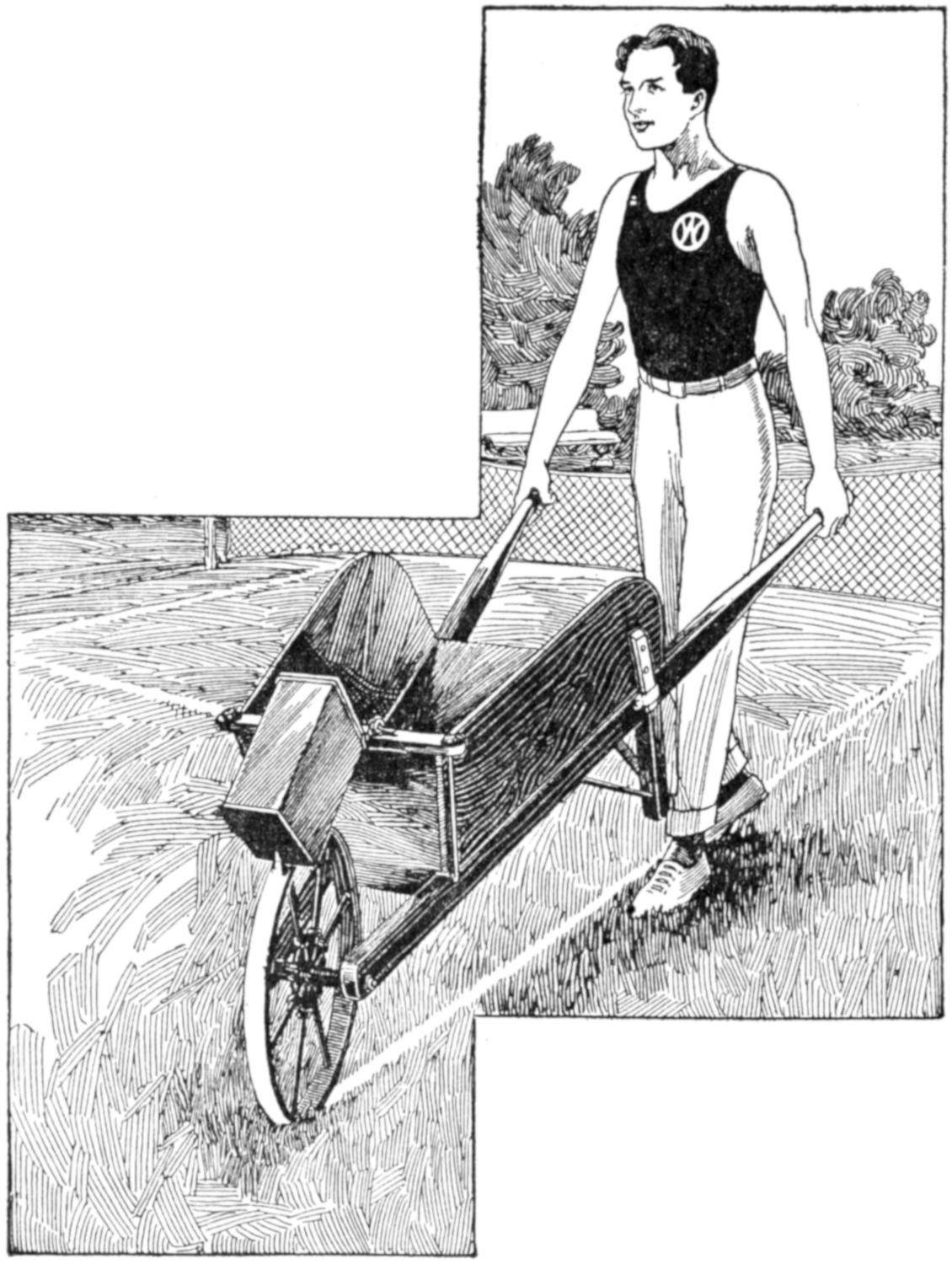
Tennis Courts may be Laid Out Quickly by the Use of a Wheelbarrow to Which a Can Containing a Thin Lime Mixture has been Fixed, as Shown
Many home tennis courts are not provided with a marker, and the use of a wheelbarrow for this purpose has been found convenient. A can provided with hooks at its upper edge was attached to the front of the wheelbarrow, as shown in the sketch, and the lime mixture, very thin, poured into it. Holes were made at the lower edge of the can so that the liquid ran onto the wheel and was transferred to the court. The holes must be made large enough so that they will not clog quickly, and the mixture must be very thin. It is easy to cover the outline several times if necessary. Hence, to use a thin mixture will be found economical, rather than to waste time removing sediment from the spout.
Portraits taken out of doors sometimes show unusually heavy shadows under the eyebrows and chin. The printing of these through the negatives may be altered by applying a little red or blue color on the glass side of the negative. Stippling the surface by contact with the texture of the skin also aids in removing the heaviness of such shadows.
[398]
Mat varnish, containing a small amount of iodine dissolved in it, and applied to the glass side of a negative, will cause much lighter prints than if the negative is permitted to remain with heavy shadows. The varnish will dry quickly, and it may then be scraped off carefully or removed with benzole from the parts of the negative which are not to be lightened. Care must be taken in scraping away the varnish in order to prevent scratches.
The whirling fan illustrated is more convenient than a fan of the ordinary type, and may be made by a boy of only moderate mechanical skill. The materials necessary for its construction are easily available in the home. The sketch at the center shows the completed fan, and the smaller sketch at the right illustrates the method of operation. The details of construction are shown in the working drawings.
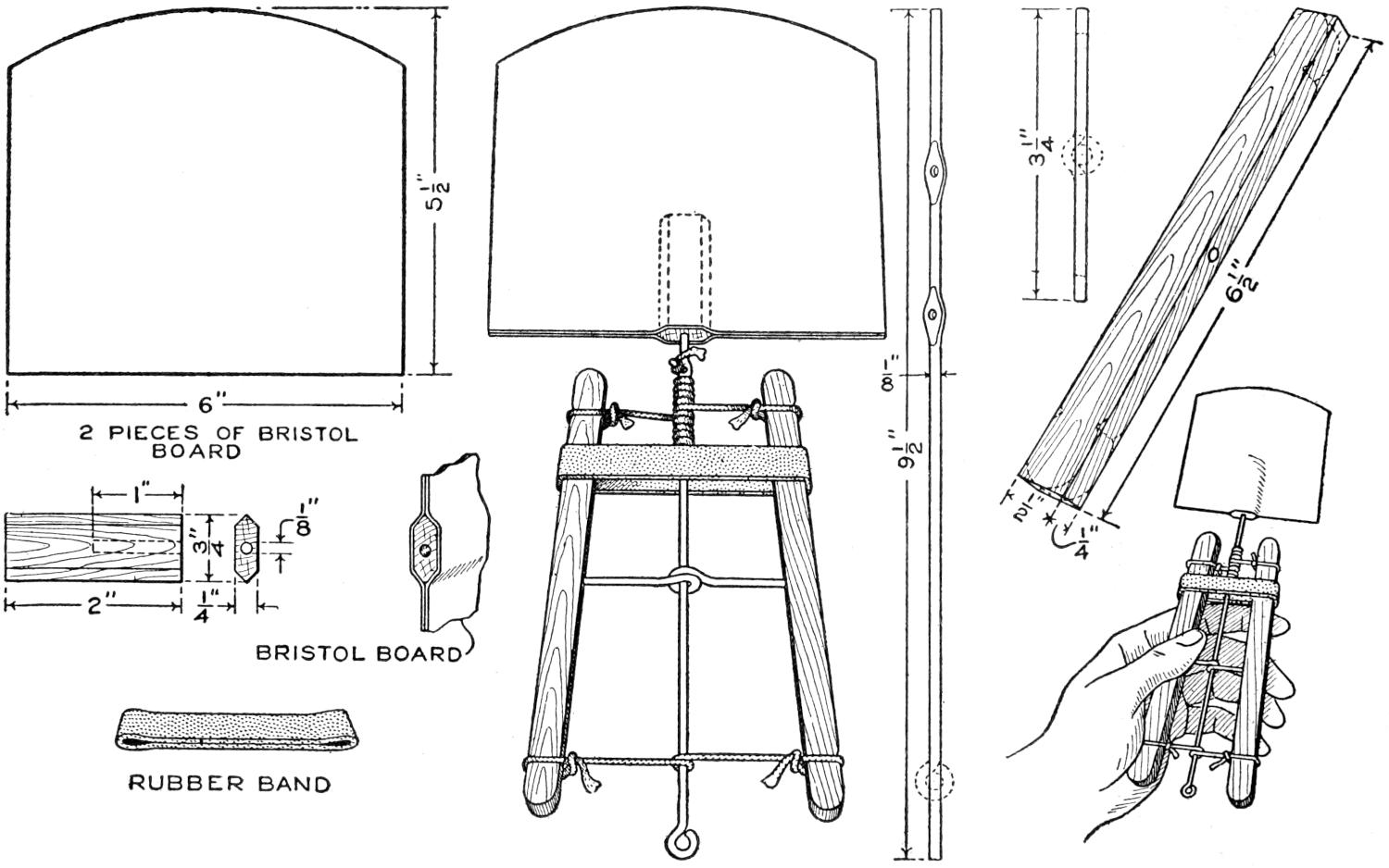
The Whirling Fan Is Superior to One of the Ordinary Variety and may be Made at Home of Materials Readily Available. The Small Sketch at the Right Shows the Method of Operation, and the Details of Construction are Shown in the Larger Sketch and in the Working Drawings
The wing of the fan is cut from a sheet of Bristol board, and is 6 in. long and 5¹⁄₂ in. wide. It is formed by gluing two pieces together, the upper end of the driving shaft being glued into place at the same time. The small sketch at the left shows the size and shape of the piece of wood into which the driving shaft is fastened at its upper end.
The driving rod, shown at the right of the larger sketch, is ¹⁄₈ in. in diameter and 9¹⁄₂ in. long. The flattened portions near the upper end are drilled to receive the ends of the cords which wind and unwind on the shaft at the top of the handles. A brace of similar wire is fixed near the middle of the handles so that they pivot on its ends when the lower ends of the handles are pressed together, as shown in the sketch at the right. The handles are of wood, ¹⁄₄ in. thick, ¹⁄₂ in. wide, an 6¹⁄₂ in. long. Their ends are rounded and slight notches are cut into the corners near the ends, to provide for the tying of the cords.
A wide rubber band, slipped over the handles near their upper ends, causes them to close at the top, and when the fan is in use this will reverse the rotation of the fan. It is necessary only to squeeze the handles inward, and the reverse action is repeated.
[399]
Electric sparks may be photographed with simple equipment, and the process offers a diversion from the common subjects for photography. The materials necessary are a spark coil and current source, a photographic plate, facilities for developing it, and a sheet of tin foil. The illustration shows a typical photograph of an electric spark, and the variety possible is unlimited.
The process, which must be performed in a dark room with a ruby light, is as follows: Over the mouth of a small glass bottle, partly filled with talcum powder, tie a piece of cheesecloth, to act as a sieve. Arrange the material on a table, the sheet of tin foil lying flat, and a photographic plate on top of it, coated side upward.
Spread a thin layer of the powder on the plate, through the sieve. Attach a needle to an electric wire and fix the other end of the wire to one of the secondary posts of the spark coil. Attach a second wire to the other post of the spark coil and to the sheet of tin foil. Care must be taken in handling the needle that only the insulated portion, where it is joined to the wire, comes in contact with the fingers, or a shock may result. Place the point of the needle near the middle of the plate and turn on the current, permitting it to produce a spark of not more than one second’s duration. If the exposure is longer than that the result will not be satisfactory. Wipe off the powder and develop the plate. If care has been taken in the process, a photograph similar to the one shown in the illustration will result.
¶Shoulder hooks fixed about a shop, so that handsaws may be placed on them by the handle, will save damage to saws.
Being called to dinner by the stirring peal of a bell made of a cannon shell is a novelty in use in Toronto. The bell shown in the sketch was made of a 3-in. brass shell, and when struck with a gavel gives out tones that penetrate throughout a large house.
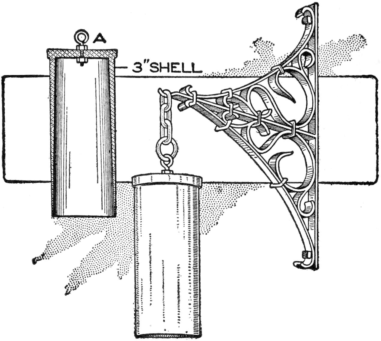
Its Tones Penetrate a Large House
The cap piece was removed at A, and an eyebolt fastened in place with a nut on each side. The gong was suspended from a wall bracket made of a band of brass fastened to the wall.—Contributed by James B. Noble, Toronto, Canada.
Magazines are often thrown away because of the rapidity with which they accumulate. Since most readers care to save only certain articles, a good plan is to tear the magazines apart, removing the desired articles and binding them in a separate volume. If this is carefully and systematically done, and an index prepared, the volume will be of value and interest.
Housewives, and others who appreciate the need for a smooth surface on a flatiron, will find the polisher shown in the sketch a convenient aid in keeping their irons in proper shape.
A wooden block, about 4 in. wide and 6 in. long, was fitted with five thin[400] patches of beeswax as shown in the upper sketch. The holes bored into the wood were made large enough to fit the wax, which may be purchased in large thimble-shaped pieces. A double layer of linen, or other strong cloth, was fitted over the side having the wax imbedded in it, and a piece of fine emery cloth was folded over the other side of the block. A band of sheet iron riveted together so as to fit snugly over the edges holds the cloth and emery cloth in place.
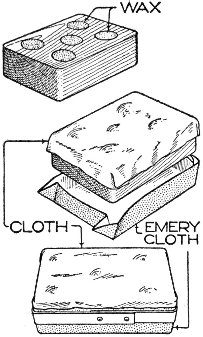
The flatiron may be polished by rubbing it on the emery-cloth side of the block and waxed slightly by rubbing it over the cloth side.
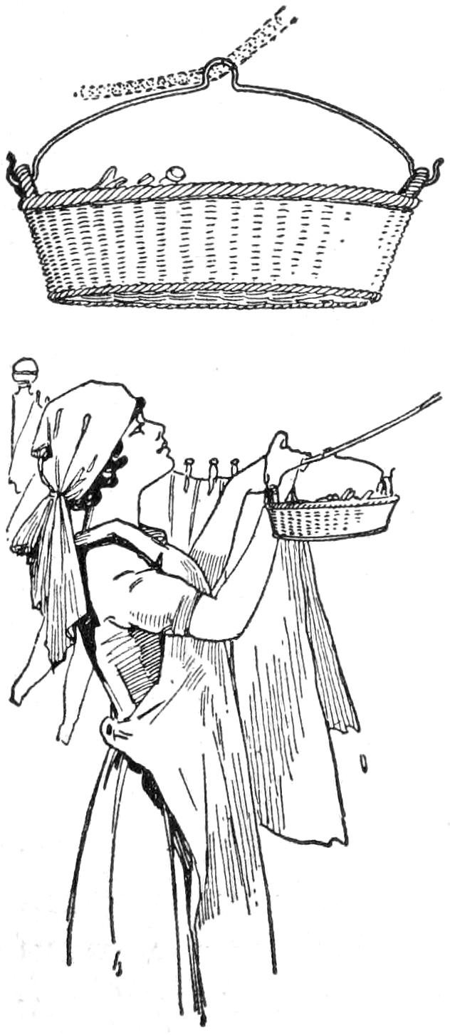
To conveniently support a clothespin basket along the line on which the clothes are being hung, a wire support can be provided, bent to form a hook at both ends and the center shaped into a V-bend. With the basket supported by the two ends, the wire can be slid along the clothesline as required.—Contributed by N. R. Moore, Cherokee, Iowa.
¶Varnishing should as a rule be done in a room having a temperature of 80° F., and in some instances 15° higher is desirable.
A leather patch fixed over a tire puncture with shellac will be found to give satisfaction and may be attached easily. Cut the patch somewhat larger than the puncture and thin out its edges with a knife. Melt flakes of shellac in a flame, fusing them, and rub the hot mixture on the patch and tire, smoothing it down quickly. Such a patch may be placed over a plug and will aid in holding it in place.—Contributed by Robert C. Knox, Petersburg, Fla.
Camphor is the motive power which drives the device shown in the illustration, and it will cause the whirligig to revolve for several days, or until the camphor is consumed.
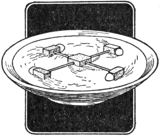
The whirligig is made of a piece of cork, ¹⁄₂ in. square, with a needle stuck into each of its four sides. Smaller pieces of cork, to which pieces of camphor have been fixed by means of sealing wax, are attached to the ends of the needles. Care should be taken to keep the needles and cork free from oil or grease, as this will retard their movement. As soon as the device is placed in a dish of water it will start whirling and continue to do so as long as motive power is supplied. A small flag or other ornament may be attached to the center cork.
To test a file hold it so that the light will be reflected sharply from the teeth and observe whether their edges are flattened and appear as white lines. If so, the file is dull and should be recut if of considerable size and value.
Files should not be thrown into drawers and mixed with other tools, but should be carefully set in racks or[401] drawers for the purpose. A mechanic would not throw a straightedge into a drawer containing other tools, and a file should be given similar consideration, as every nick in the teeth impairs the efficiency of the file.
Files may be sharpened by dipping them into sulphuric acid, but care must be taken not to permit the acid to come into contact with one’s clothes or person. Water is used to wash off the acid.
Files should be provided with individual handles. This prevents injury to the hand of the worker and aids in the proper use of the file. Handles should be carefully fitted and be made of a size proportionate to the file. In removing a handle from a file, strike the handle at the end nearest the file, by sliding a piece of hard wood along the surface of the file, as the blow is struck with it. Do not use another file or metal object in thus removing a handle, as it will injure the latter.
Teaspoons may be made into alluring trolling spoon hooks, of a size suitable for catching large fish, by the addition of hooks, as shown in the sketch.
Drill ¹⁄₈-in. holes near the end of the spoon handle, the tip of the bowl, and near the handle of the latter.
Procure three sets of triple hooks, a line swivel, and a strip of lead, about 1 in. long. Rivet one end of the swivel and the loop of one of the triple hooks into the hole of the handle. Wire the lower end of this triple hook to the handle and with the same piece of copper wire secure a second triple hook at the thin part of the handle. Drill a hole through the lead strip and rivet it, together with a third triple hook, into the upper hole of the bowl. Fix the lower end of this hook by binding it with copper wire, through the hole near the tip of the bowl.
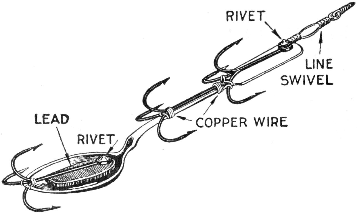
Once a Fish has Struck This Bait, It Is Seldom Able to Escape
This hook has been tested in the waters of Puget Sound and is a deadly lure for rock cod, and other fish weighing up to 12 lb. The famous barracuda and rock bass of the Catalina Islands have also been caught with it. By permitting the lure to sink to the bottom and bringing it up a yard or two with a quick jerk, it acts as a “jig” bait. It may also be used in trolling. Once a fish has struck, it is seldom able to escape.—Contributed by O. P. Avery, Los Angeles, Cal.
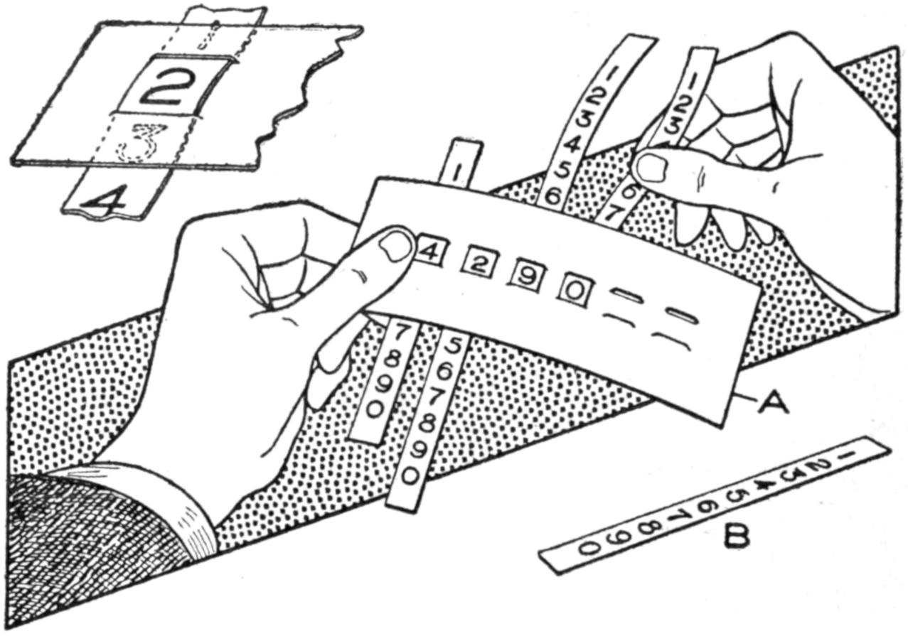
An Accurate Account can be Kept of Parts or Score for Any Game by Pulling the Strips
From unruled paper cut a piece, as shown at A in the sketch, and make slits parallel and evenly spaced with a sharp knife. Also cut six strips, similar to the one shown at B, to fit the slits cut in A. The strips are numbered as shown and inserted on the under side of A, and by pulling the strips as shown, one can count up the number of parts or keep tally on any game. By making more slits and using more strips very large numbers can be recorded.
¶Be sure to keep the screw and nut in the jaws of a drill chuck clean and well oiled, to prevent broken screws.
[402]
A convenient method of uncorking a bottle, from which liquid is to be poured frequently, is to thread a strong string or cord through the cork, tying it in a loop, which remains at the opening of the bottle. The cork may be removed easily by drawing on the string. This is more satisfactory than the use of a corkscrew, as the latter frequently tears the cork.—Lee A. Collins, Louisville, Ky.
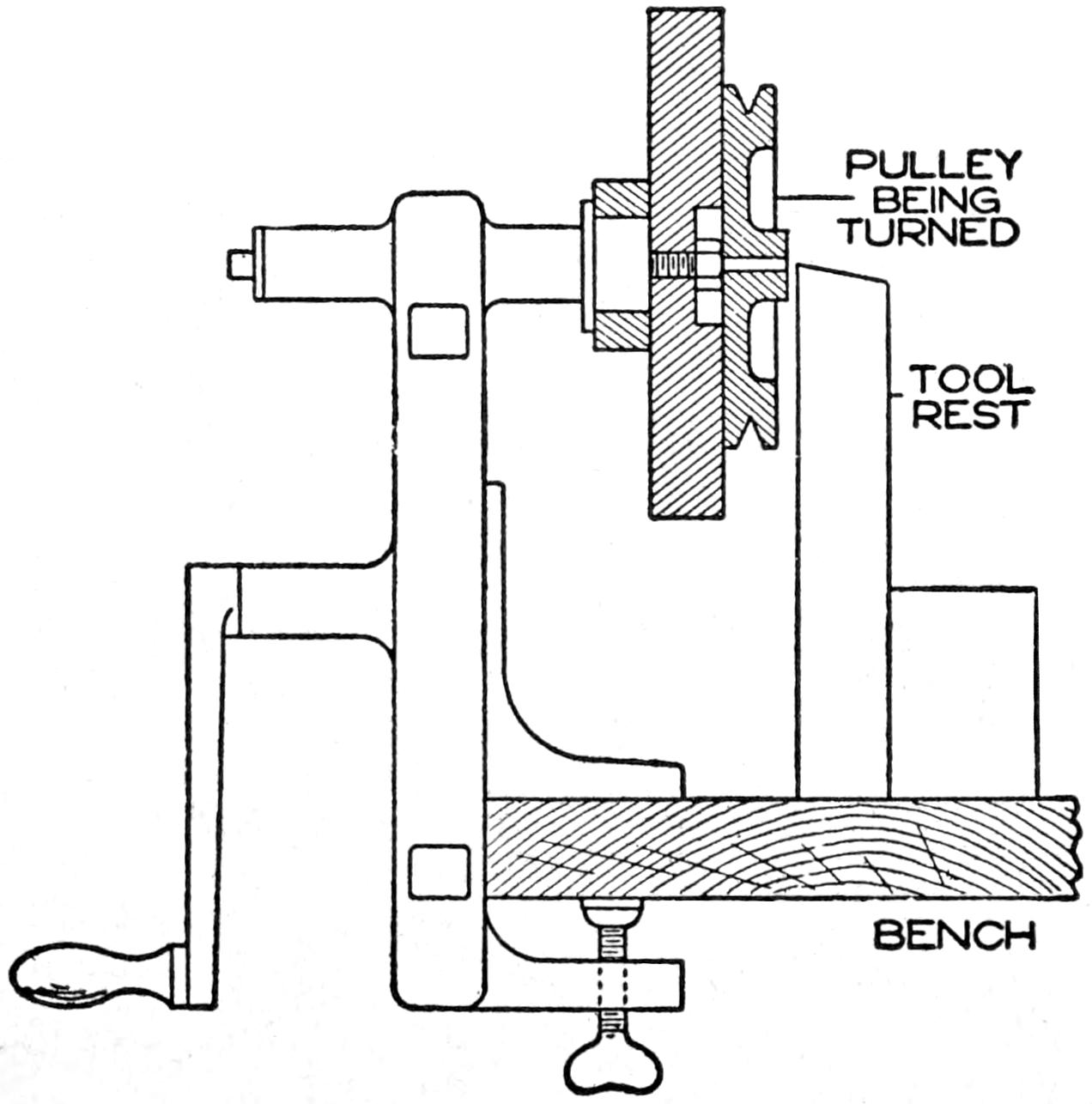
The Hand Emery Grinder of the Home Workshop Used as a Substitute for a Lathe
The experimenter often requires small turned-wood pulleys, circular bases for switches, etc. To produce these it is not necessary to have recourse to a wood lathe, if a good emery grinder is at hand. Simply clamp the grinder firmly to the workbench, remove the grinding wheel, and fasten on a block to serve as a faceplate. This may be held in place by the nut that holds the wheel and should be trued up with a small chisel when in place. A tool rest may be improvised by temporarily nailing one or more blocks of wood to the bench. The article desired should be first roughed out with a saw and then fastened to the faceplate with screws or brads, after which the actual wood turning will require very little time.
The devices for the bathroom illustrated may be made easily and contribute to the comfort, convenience, and, in the case of the fixed window pole, to the safety of the room. A wall curtain, A, placed on the towel rod, or hung on the wall beside the washbasin, is especially convenient in keeping the walls unsoiled by children who make use of the room and are likely to splash suds while washing. Double roller shades on the window, as at B and C, give light and privacy as well.
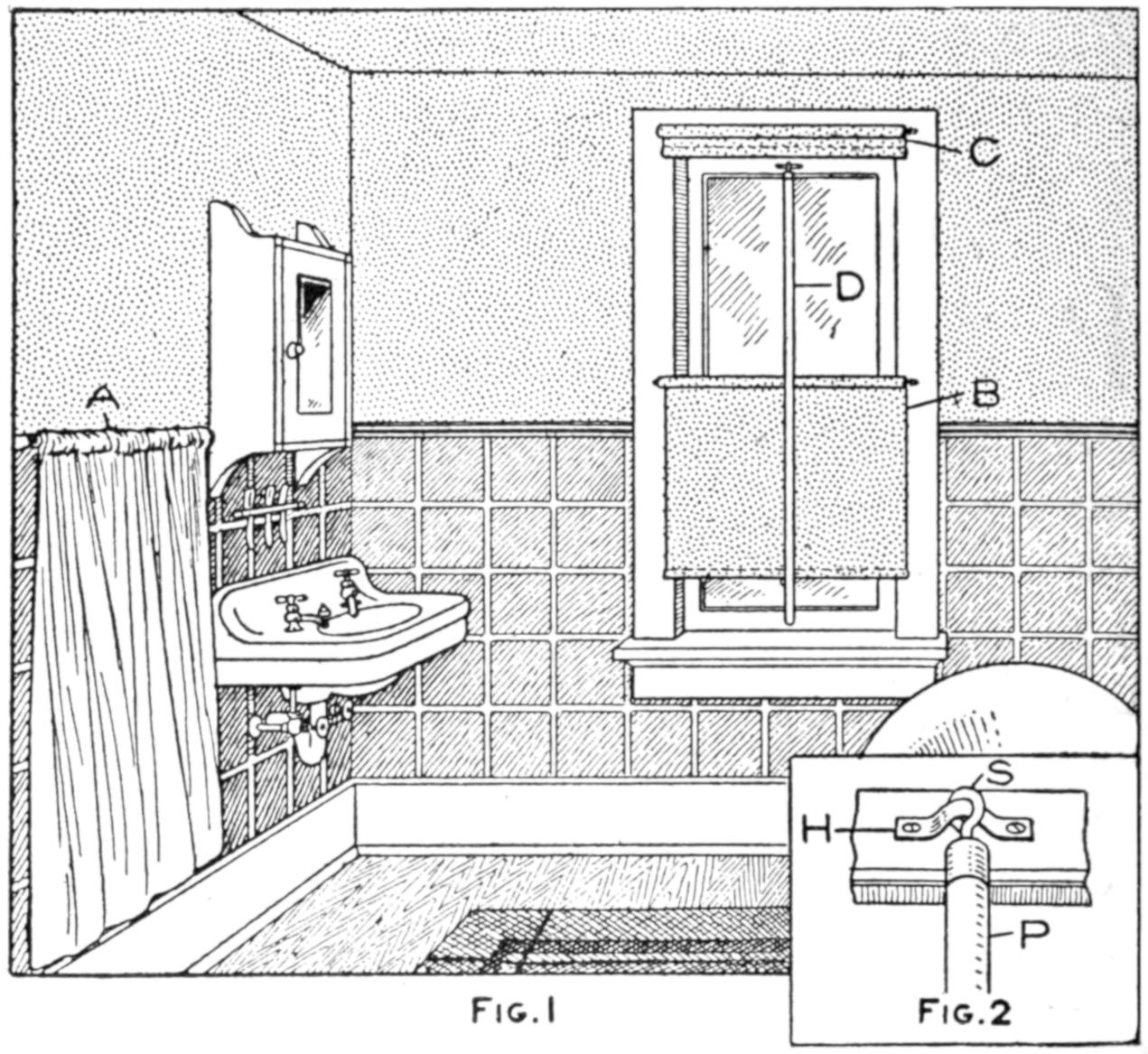
The Fixed Window Pole Is an Inducement to Ventilation; the Curtain Protects the Wall, and the Lower Shade Gives Light with Privacy
Poor ventilation in bathrooms occasionally causes asphyxiation and is often a menace. The permanent fixing of the window pole D makes it convenient to open the window, which operation is often neglected through fear of drafts from the lower sash and the lack of a pole. Fig. 2 shows the top of the pole P, provided with a screw eye, S, which is fastened to a metal strip, H.—D. L. Hough, Toledo, Ohio.
To prevent a sewing machine that has been oiled from soiling the material, the following is a good method: Tie a small piece of ribbon or cotton string around the needle bar near the point at which it grips the needle.
[403]
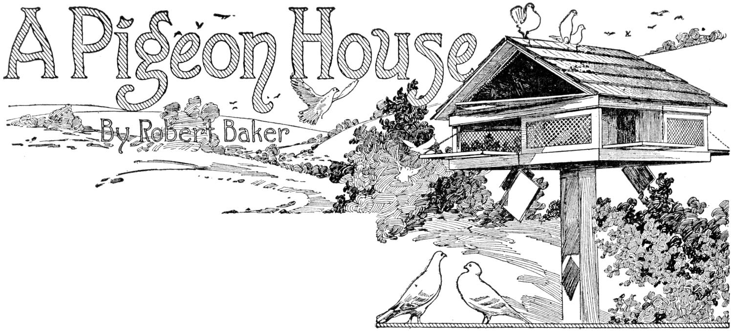
A Pigeon House
By Robert Baker
Pigeon houses need not be eyesores, as is often the case, but may be made to harmonize with the surroundings, adding beauty to a dull spot, and even making the grounds of a home more attractive. The house described will accommodate 20 pigeons, and additional stories of the same type may be added to provide for more. Nearly all of the wood necessary may be obtained from boxes, and the other materials are also readily available at small cost. The construction is such that a boy handy with ordinary carpentry tools may undertake it successfully.
The house is constructed in general on principles used in buildings, having a framed gable roof, rough-boarded and shingled. The interior arrangement is original, being based on the Indian swastika or good-luck sign. While the construction is simple, it must be carried out systematically. The process outlined also follows in general the typical methods in building construction.
The foundation need not be considered, since the house rests upon a post, and the construction thus begins with the lower story. The floor and the ceiling are similar in construction, as shown in Fig. 1. In framing them into the lower story, as may be observed in Fig. 8, the cleats are placed below on the floor and above in the ceiling. The construction is identical, however. The cleats are fastened to the boards with screws, although nails, clinched carefully, may be used. The 4-in. hole at the center should be made accurately, so as to fit the shoulder portion at the top of the post, shown in Fig. 2. The latter may be cut of a length to suit; about 9 ft. will be found convenient. The notches in the top of the post are to fit the ridge pole and center rafters of the roof frame, as shown in Fig. 10. They should not be made until the house is ready for the roof boards.
The pieces for the compartments, as arranged on the floor in Fig. 3, are made next. Figs. 4 and 5 show the detailed sizes of these pieces, of which four each must be made. The sizes shown must be followed exactly, as they are designed to give the proper space for entrances and to fit around the 4-in. square hole, through which the post is to fit. The pieces marked A, B, and C, in Figs. 4 and 5, correspond to those similarly marked in Fig. 3.
The pieces are nailed together to form the swastika in the following manner:
Mark the pieces A, B, and C, as shown. Measure 4 in. from one end of each piece marked A, and square a pencil line across, 4 in. from the end. Arrange the pieces in pairs. Place one end of one piece against the side of the other piece in the pair, so that the pencil line is even with the end, permitting the 4-in. portion to project. Nail both pairs in this position. Then fit the two parts together to form a 4-in. square in the center, as shown in Fig. 3.
Fit the pieces C to the pieces B at an angle, as shown in Fig. 3, trimming off the projecting corners where the pieces are joined. Nail them together, and they are ready to be fixed to the[404] end of the pieces A, already nailed. By nailing the joined pieces B and C to the end of the pieces A, as shown in Fig. 3, the swastika is completed. Fix it into place, with the center hole exactly over the square hole in the floor, by means of nails or screws driven through the floor.
Two small strips must now be nailed to the floor at each side of the swastika. They should be exactly 4¹⁄₂ in. long, and are to hold the slides, Fig. 9, which shut off the various compartments. The slides are shown hanging by chains in the headpiece of this article, and are shown in place in Fig. 8.
Fix the ceiling into place in the same manner, being careful that the square holes fit together, and that the cleats are on the upper side. Turn the construction over and fix into place the small strips for the slides, as was done on the floor.
The fixed screens, Fig. 6, and the doors, Fig. 7, are constructed similarly. They are built up of ¹⁄₂-in. wood, and vary in size to fit their respective places in the framework. Observe that the fixed screens are ¹⁄₄ in. higher than the doors, and that they are fastened between the ceiling and floor, bracing them. The wire grating is ¹⁄₂-in. square mesh, and is fixed between the pieces of the doors and the screens when they are built up.
The doors are shown secured by combination strap hinges, bent over the baseboard. Plain butts may be used and the lower portion of the hinge covered by the baseboard, a recess being cut to receive the part covered. In the latter instance the doors should be fixed into place immediately after the screens are set. Catches and chains may then be placed on the doors. Next nail the baseboards into place. They are 2¹⁄₂ in. wide and may be mitered at the corners, or fitted together in a square, or butt, joint. The latter joint may be nailed more readily.
The slides, shown in Fig. 9, may now be made and fitted into their grooves. The handles are made of strips of band iron, drilled for screws and bent into the proper shape. It is important that the slides be constructed of three pieces, as shown, so that they will not warp or curve from exposure. The main piece is cut 7³⁄₄ in. long, and the strips, ¹⁄₂ in. square, are nailed on the ends.
The construction of the framing for the roof should next be taken up. This probably requires more careful work than any other part of the pigeon house, yet it is simple, as shown in Fig. 10. Note that the rafters are set upon a frame, or plate as it is called, built up of pieces 3 in. wide. It should be made ¹⁄₄ in. wider and longer on the inside than the ceiling board, so as to fit snugly over it. The joints at the corners are “halved” and nailed both ways. This gives a stronger structure than butting them squarely and nailing them. The end rafters should be fitted in before fixing the others. It is best to make a diagram of the end of the roof framing on a sheet of paper, or a board, and to fit the rafter joints in this way before cutting them. The rafters are then nailed into place.
The “rough boards” to cover the rafters may now be nailed down. They are spaced ¹⁄₂ in. apart so as to permit thorough drying, as is done in larger buildings. They project 2 in. beyond the ends of the plate frame, supporting the rafters. A ¹⁄₂-in. strip is nailed over the ends to give a neat finish. The roof may be shingled, or covered with tar paper, or any roofing material.
Nail a 1-in. strip under each end of the roof and nail the gable ends into place. One gable end is provided with a door, as shown, and the other has an opening fitted with a wire screen of the same size as the door.
The gable story rests on the lower story, and the notches in the top of the post should fit snugly to the ridge and center rafters, as shown in Fig. 10. This will aid in supporting the house firmly. If additional stories are added it would be well to place a post at each corner of the house. The upper story may be removed for cleaning, or for transporting the house.
[405]
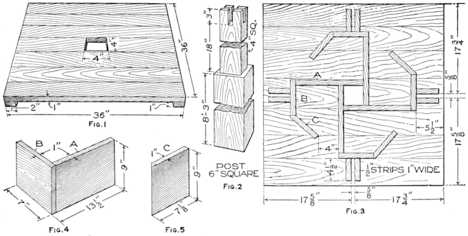
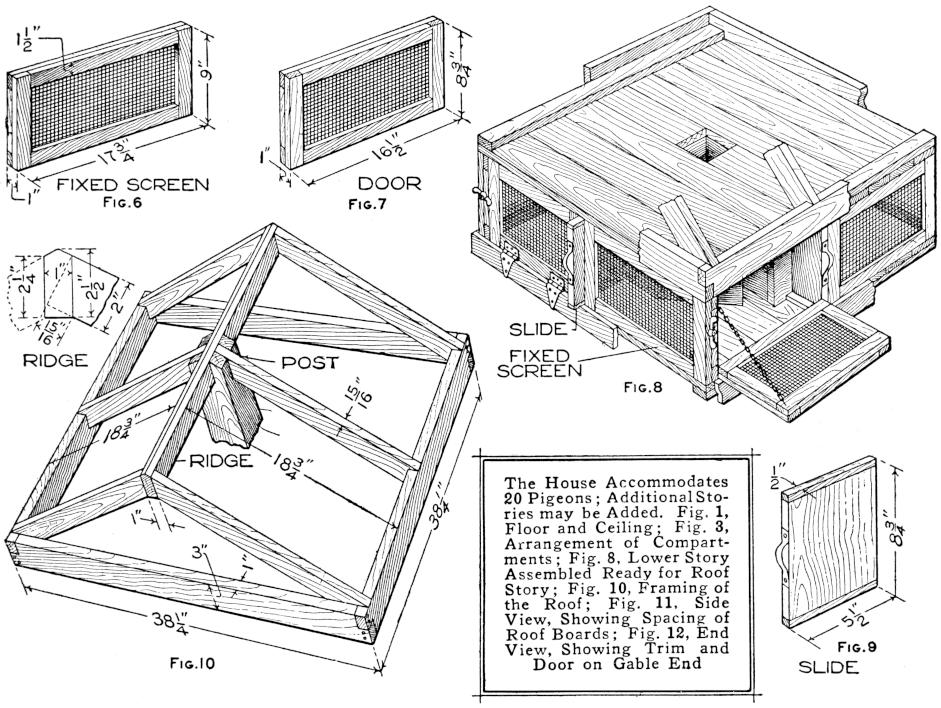
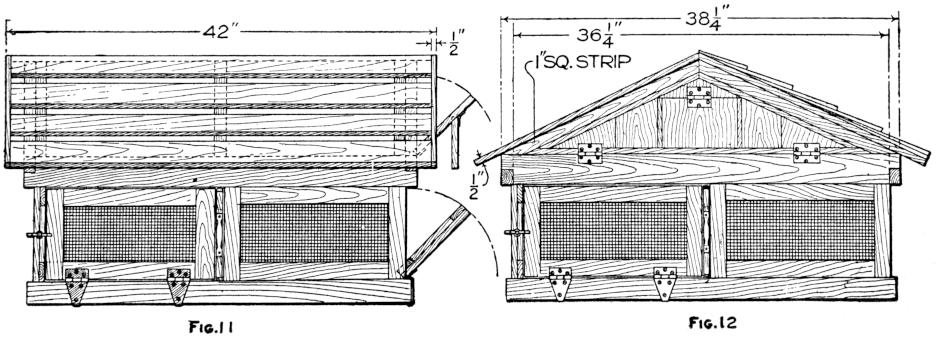
| Fig. 1 | Fig. 2 | Fig. 3 | |||
| Fig. 4 | Fig. 5 | ||||
| Fig. 6 | Fig. 7 | Fig. 8 | |||
| Fig. 10 | |||||
| The House Accommodates 20 Pigeons; Additional Stories may be Added. Fig. 1, Floor and Ceiling; Fig. 3, Arrangement of Compartments; Fig. 8, Lower Story Assembled Ready for Roof Story; Fig. 10, Framing of the Roof; Fig. 11, Side View, Showing Spacing of Roof Boards; Fig. 12, End View, Showing Trim and Door on Gable End | Fig. 9 | ||||
| Fig. 11 | Fig. 12 | ||||
[406]
The post should be sunk into the ground about 2¹⁄₂ ft. and set into a concrete foundation, if convenient. This will insure a more nearly permanent as well as a more rigid support. Care should be taken that the post is set plumb and this can be accomplished if a plumb bob is used. The post should be braced to keep it vertical, particularly if a concrete foundation is poured and tamped around it.
The construction should be painted two coats, inside and out, of a color to harmonize with buildings or other surroundings.
The cost of building the house shown in the illustration was $3.50 and by using tar paper for the roof and discarded wire mesh, hinges, and other fittings, this may be reduced considerably.
¶In matching molding into corners it is often difficult to make miter joints. The molding may then be “coped” together by matching the end of the piece to be joined to it with the curves or surface of the molding. A coping saw is used in sawing the irregular end.
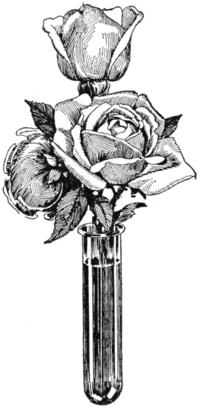
Roses may be colored without any detrimental effect by placing their stems in a solution of 100 cubic centimeters of water, 2 grams of saltpeter, and 2 grams of an aniline dye. A centerpiece of roses colored to represent the national colors was made in this way and proved very effective as a table decoration. A convenient way to color the flowers is to place their stems in a test tube containing the mixture.—Contributed by Chester Keene, Hoboken, N. J.
Serviceable trays for use in developing and printing photographs may be made quickly of cardboard boxes of suitable sizes. Where one is unable to transport readily a full photographic equipment these trays will prove convenient as well as inexpensive. They are made as follows:
Procure boxes of proper sizes and see that they have no holes or openings at the corners. Melt paraffin and pour it into the box, permitting it to cover both outside and inside surfaces. If the paraffin hardens too rapidly the box may be heated and the work completed.—Contributed by Paul A. Baumeister, Flushing, N. Y.
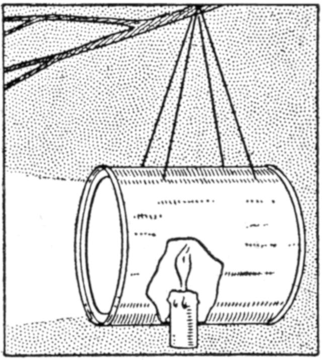
Campers, and others who have need of an emergency lantern, may be interested in the contrivance shown in the sketch, which was used in preference to other lanterns and made quickly when no light was at hand. It consists of an ordinary tin can, in the side of which a candle has been fixed. A ring of holes was punched through the metal around the candle and wires were placed at the opposite side for a support. The glistening interior of the can reflects the light admirably.—Contributed by F. H. Sweet, Waynesboro, Va.
¶Interior woodwork may be made proof against ordinary flame by coating it with silicate of soda, known as water glass.
[407]
Quick delivery of small packages within a two-mile radius can be accomplished with a bicycle by a sturdy boy. An ordinary bicycle is used, preferably one with coaster brake and mudguards. Iron braces, ¹⁄₄ by 1¹⁄₄ in., are shaped to make the framework, and the ends are looped to fasten around the frame of the bicycle and the supporting fork of the third wheel. This wheel is a bicycle front wheel with a fork. A mudguard on the third wheel is desirable. Make the iron parts as detailed, and fasten them into place. The body is made of ⁷⁄₈-in. wood, preferably oak. The upper portion of the body is cut to receive the top brace, which is not in the way in loading or unloading the packages. Fasten the box with ¹⁄₄-in. carriage bolts, using a spring washer under the nut wherever a joint is made between wood and iron. A canvas cover can be cut to fit the top and secured at one end only, with three catch knobs on the sides and corresponding eyelets in the canvas, keeping the dust and rain from the interior of the body.
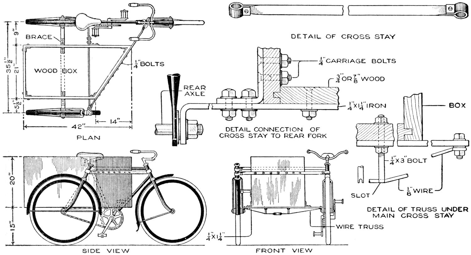
An Ordinary Strong Bicycle can be Made into a Substantial Delivery Car by the Addition of a Body and a Third Wheel
It is a good plan to stiffen the body with corner braces, using ¹⁄₈ by ³⁄₄-in. band iron. The floor of the body should be strongly fastened, tongue-and-groove boards being used, and the side corners should be fitted with iron braces at the bottom. The body may be extended farther over the rear, if more loading space is required.
One coat of priming and one of paint finishes the box, and with the name of the merchant on the front and rear, the whole makes a neat advertising feature. Regarding the selection of a bicycle, since great speed is not essential, the lower the gearing is, the easier it will be to propel the load, and for ordinary work, where only small grades are covered, a gear of about 65 will be found efficient.
Adhesive tape is useful in the shop and for the home mechanic, for many purposes: to mend broken handles temporarily; to bind up a cut finger; to prevent a hammer or ax handle from slipping in the hands, by applying tape around the handle; for making a ferrule for an awl, chisel, etc.; around the nail set it will keep that tool from jarring the hand; around a lead pencil in the vest pocket as a guard.
[408]
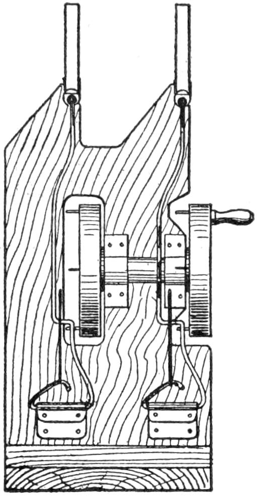
For use in the mimic battles which most boys like to stage in this war time, an interesting mechanical toy that a boy can easily make of materials picked up in the workshop, is a machine gun having a magazine for wooden bullets, and which can be made as a single or a double-barrel gun. The construction of the single-barrel arrangement is detailed in the sketch and the modification for a double-barrel gun is shown in the smaller diagram. It is a duplicate of the first type, suitably mounted as shown. The gun is fired by turning the crank on the wheel and the bullets can be quickly replaced in the magazine at the top.
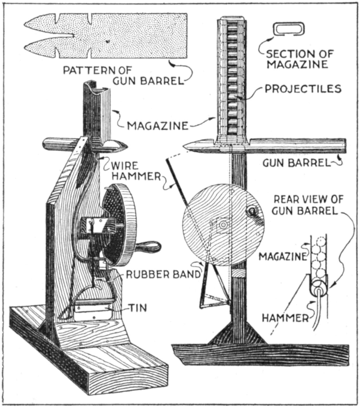
The Machine Gun is Fired by Turning the Crank at the Wheel, the Pins on the Latter Drawing Back the Hammer, Which is Hooked Up with a Rubber Band
The support for the gun is made of wood and braced strongly at the base. The gun proper is set into the top of the vertical piece, as shown, and the magazine, which is bent from a piece of tin to the shape detailed in the sectional view, fits on top of the breach of the gun. The hammer, which drives the bullets, is made of a piece of stiff wire bent to the shape shown. The lower curved end is connected to a small nail set on a block at the shaft of the wheel. To fire the gun, the hammer is drawn back by contact with the small nails set into the side of the wheel. As the wheel is turned, the nails grip the hammer and then suddenly release it, driving out the lowest bullet each time. The bullets are piled in the magazine, as shown in the detailed view at the right, where the rear view of the gun barrel is indicated.—Edward R. Smith, Walla Walla, Washington.
A cumbersome part of a commercial photographer’s equipment when “on the road” is his set of printing frames. Amateur photographers who have cameras using plates of more than one size find these frames an expensive part of their outfits. A method that is practical and inexpensive for these requirements in many cases, is as follows: Place the sensitized paper in the plate holder with the emulsion side up. Then put the plate in the holder in the same way as if about to expose it in a camera, but with the emulsion side down, so that the sensitized side of the paper and the emulsion side of the plate are in contact. The paper and plate are thus held in close contact without the use of springs, as in the regular printing frames. The plate and paper can be removed by pressing the spring catch at the bottom of the holder, and the plate is not easily moved while in place.—Francis W. Clinton, Brooklyn, New York.
¶Leaks in garden hose may be repaired by wrapping several layers of adhesive tape over the break, lapping the edges carefully.
[409]
Three wire paper clips linked together make a good weight for typewriter sheets that keep rolling or blowing back over the carriage, into the operator’s way, in a breezy office or where a fan is not properly stationed. They may be quickly applied to the end of the sheet, or batch of paper and carbon sheets, and removed as easily, saving time and annoyance.—H. P. Roy, Kansas City, Mo.
A length of chain, sewed into a hem at the lower edge of a flag makes an inconspicuous and effective weight to prevent whipping of a flag suspended from a horizontal staff. A piece of cord can be threaded through the links of a chain to prevent it from rattling, if necessary.
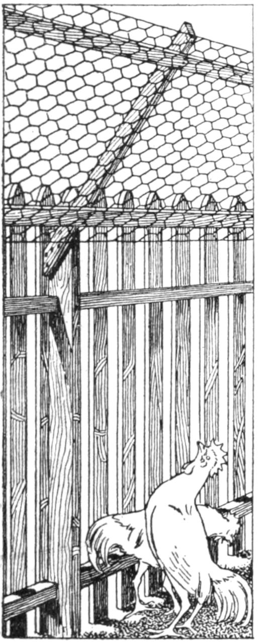
Not wanting to put a high poultry netting on my fence to keep my poultry at home, I devised the method shown, and was thus enabled to use 24-in. wire instead of 48-in., thereby effecting a saving, as well as not marring the appearance of the fence. Chickens will not attempt to fly over this wire but once or twice, as they endeavor to alight on the pickets of the fence instead of the wire, and consequently are thrown back by striking the wire. The wire should be supported at each post, as shown in the sketch.—Roy H. Poston, Flat River, Mo.
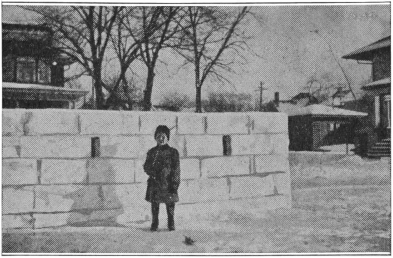
The Making of the Snow-Block Fort Is Nearly as Much Fun as Daring the Enemy to Come and Capture It or Capturing the Enemy’s Barricade
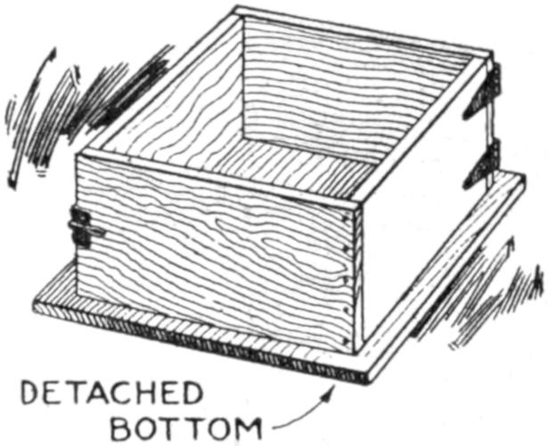
What boy does not enjoy a regular snowball fight—a battle, in fact—especially when he has a fort of his own building to defend, and his friends have one which he wants to capture? A way to build a snow fort that will not crumble easily when the enemy charges it is to pack the snow into a box form and build the structure of the snow blocks, as shown in the photograph. Portholes can be provided and when the snow melts slightly, and freezes again, a very solid wall results. The form for the block, as detailed in the sketch, is made of a box, arranged so that it is hinged at one corner and has a catch at the corner diagonally opposite. The form is set on a wooden board and when the snow is packed in solidly, the catch is opened and the form lifted away from the block. It is then carried into position and another block made on the same board. Several boards are handy in making the block quickly.—H. S., Chicago, Ill.
¶In applying varnish over an old wood surface, or on new wood that has become soiled, care should be taken to remove all traces of oil or grease with benzine.
[410]
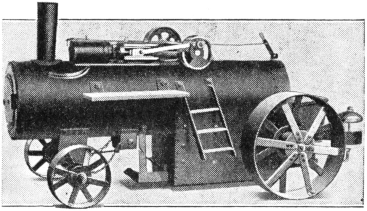
This Model Steam Tractor Is 28 Inches Long and Drives Itself, Wood and Coal being Used as Fuel
Boys, and others who like to make models, may be interested in a small steam tractor I designed and built of scrap materials around the farm shop. I used only the ordinary tools on hand in such a place. The steam engine and tractor run smoothly, and the engine propels the tractor just like a large machine of this kind. The tractor is 28 in. long and 14 in. high, and the boiler holds 1¹⁄₄ gal. The bore of the cylinder is ⁷⁄₈ in. and its stroke 1³⁄₄ in. It was made from an old iron window weight. I use wood and coal to fire the boiler, and steam can be got up in a few minutes.—Albert H. Bennington, Park River, N. D.
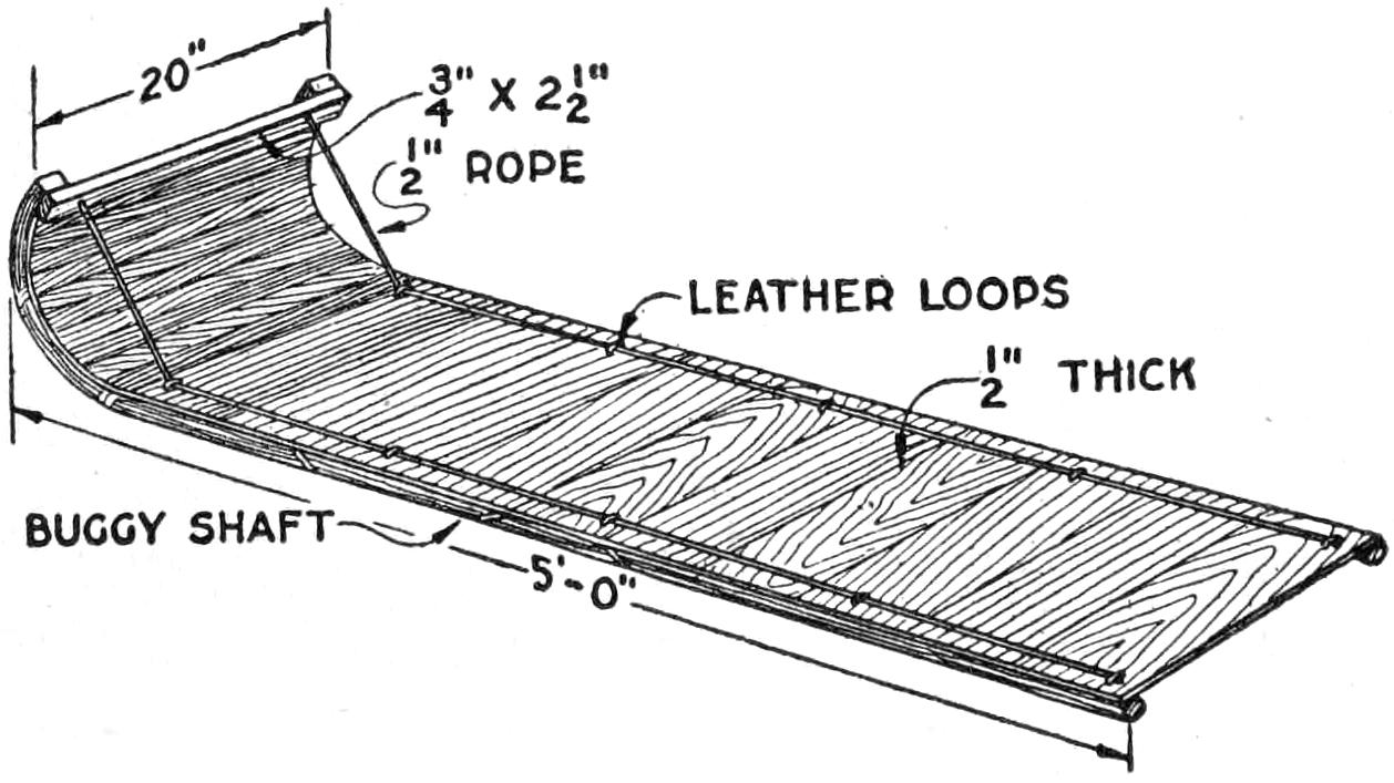
This Toboggan with Stout Runners Made from Buggy Shafts can be Used like One of the Ordinary Type, but Works Best on Frozen Snow
A method of making a strong toboggan sled by nailing a suitable bottom over sections cut from old buggy shafts, as shown in the sketch, can be adapted easily for use with poles of about the same size. They can be steamed and bent at the ends and the construction otherwise made as shown. The shafts were cut to the length indicated, the curved front end being sawed off. The bottom was carried up around the curved rear end, and a strong bracing strip was bolted across them. One-half-inch rope with leather loops provided handholds, and was also used as a brace at each side of the front of the sled. Twisted wire may also be used for this purpose. Cushions of the usual type can easily be made for the toboggan.
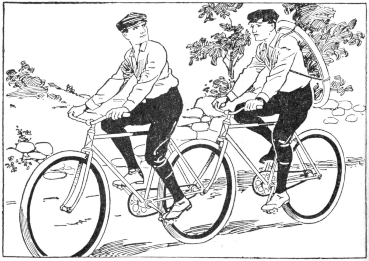
When the Front Wheel of One of the Bicycles Broke Down, They were Rigged into a Tandem, and a Distance of Five Miles to Town was Covered
On a bicycle trip, when about five miles from town, the front axle of my partner’s bicycle broke, and as neither of us wanted to walk, we had to find some way of getting us both home. We removed the front wheel from one of the bicycles, and set the front fork on the rear axle of the undamaged machine, as shown in the sketch. The axle was just long enough so that the sides of the fork could be bolted securely. By careful riding we made the distance to town with only the slight inconvenience of my partner having to carry the extra wheel on his back—J. F. G., Mountain Grove, Mo.
¶Do not touch the inner surface of a tent or shelter in the rain, as the water will drip from the spot touched.
[411]
To avoid expensive waste of paper in making large bromide enlargements the following device is useful: Cut an oblong sheet of stiff cardboard, 5¹⁄₄ by 4 in., with a central opening, measuring 3³⁄₄ by 1¹⁄₂ in. Along the lower edge of the central opening mark off five spaces of ³⁄₄ in. each, and number them from 1 to 5. Glue a strip of cardboard, 1 in. wide, at the top and the bottom of the oblong, on the back. Now glue a second strip of cardboard over each of those just attached, making the second strips slightly wider to form grooves similar to those in a sliding-top box.
Cut a piece of cardboard, wide enough to slide easily in these grooves, and about 7 in. long. In the center of it, cut an opening, 1¹⁄₂ in. long and ³⁄₄ in. wide, with the longer dimension extending across the strip. By inserting this slide into the grooves, the opening in it may be shifted to correspond to any of the five ³⁄₄-in. indications at the lower edge of the opening in the oblong frame.
Focus the enlargement on the easel and put the cap on the lens. Then pin a 1¹⁄₂-in. strip of bromide paper where a good range of detail will fall upon it. Pin the oblong card over the bromide strip and make five successive exposures, of increasing duration, by sliding the strip so that its opening is opposite the number indications on the oblong. Note the particulars of exposure at the time and later develop the strip of bromide paper. Suppose the exposures were of 8, 16, 24, 32, and 40 seconds’ duration, and upon development it was found that the first and second exposures were much underexposed and that the fifth was overexposed; the third and fourth being only slightly under and overexposed, respectively. Then the mean of these two, that is 24 plus 32 divided by 2, or 28 seconds, will be approximately the correct exposure. The use of this device will effect a considerable saving.—H. J. Gray, Lewes, Sussex, England.
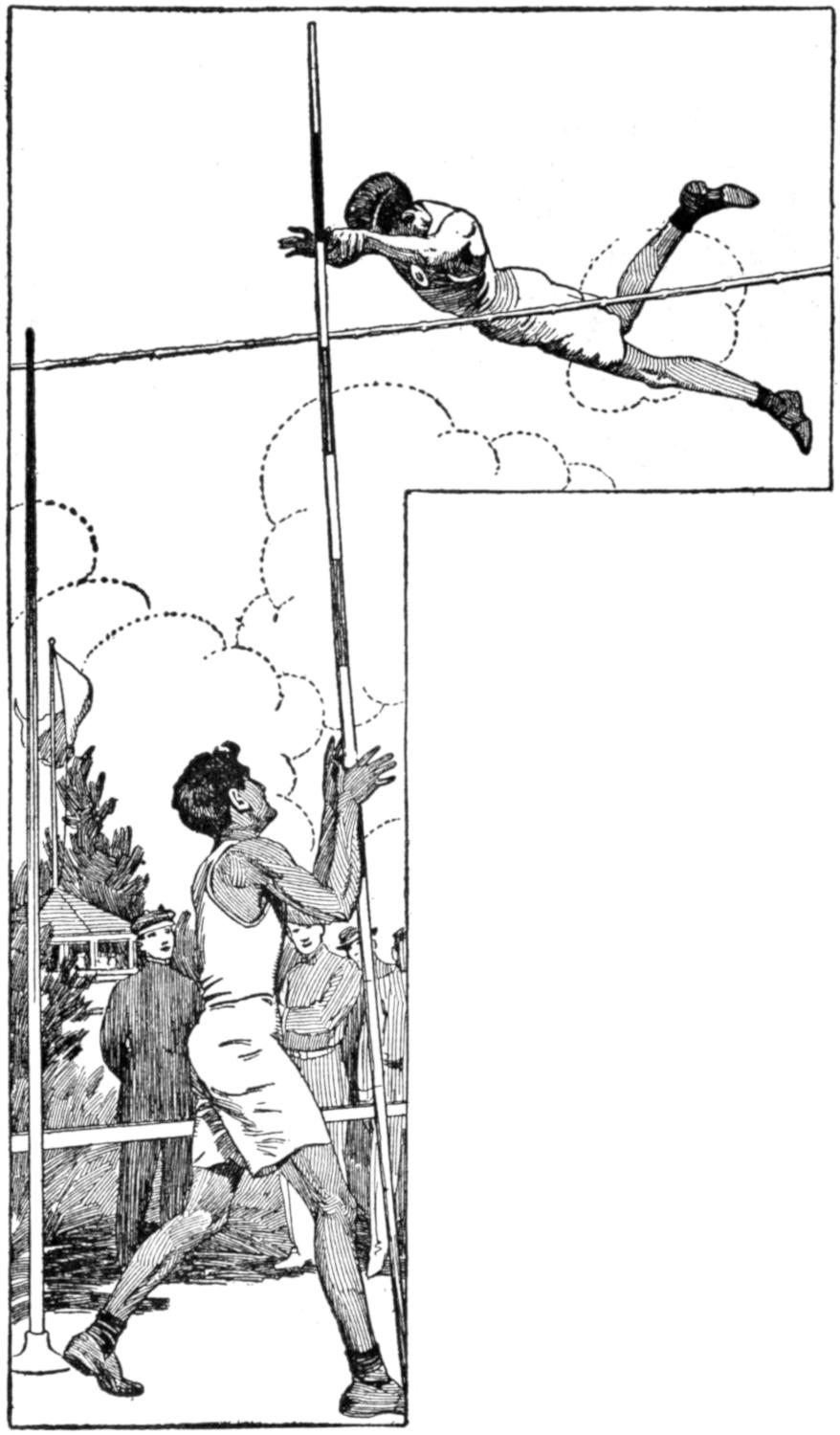
Indications on the Vaulting Pole Aid the Athlete in Finding the Proper Grip
Unnecessary delay in running off the pole-vaulting events at athletic meets is caused by the repeated testing of vaulters for the proper height at which to grip the vaulting pole. This was readily overcome by marking intervals of 1 ft. on the upper end of the vaulting poles. Vaulters judge the proper height once and thereafter may easily take the same grip with the aid of the indications on the pole.—A. B. Wegener, Madison, N. J.
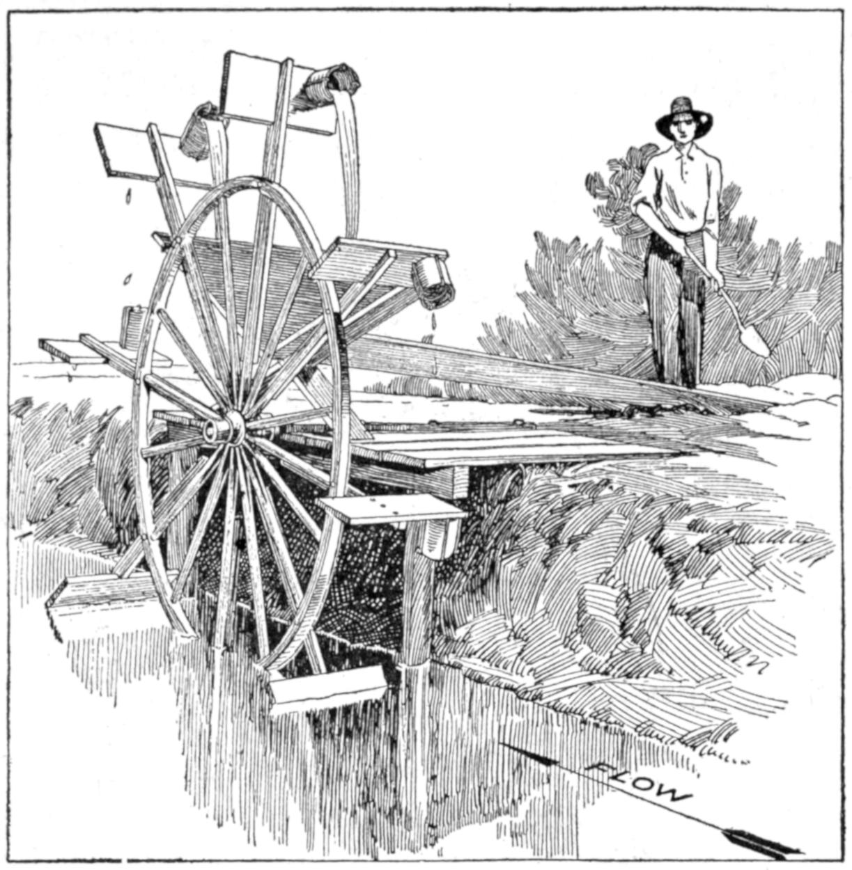
The Current of the Canal Causes the Wheel to Revolve, Carrying the Water to the Trough
The current of a canal was utilized to raise water for irrigation purposes, and other uses, by means of the homemade device shown in the illustration. A large-size buggy wheel was set on an old axle, and extensions were fixed to eight of the spokes. Paddles, 9 by 18 in. in size, were secured to the extensions, and uniform-size tin cans were fixed to the paddles, as shown. The current revolved the wheel, carrying[412] the loaded buckets upward, and the water was thus poured from them into a wide trough braced on the platform. A flume led the water to the irrigation ditches, and pipes were used to conduct some of it to the ranch house for general purposes. When the water is not desired for useful purposes the trough is withdrawn and the water drops into the canal.—Joseph Gray, Heber, Calif.
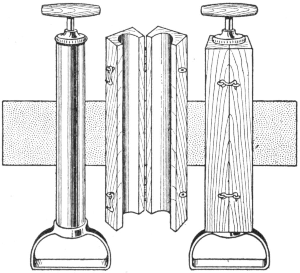
Denting of Tire Pumps is Prevented by the Use of a Case Like That Shown
The brass cylinders of many tire pumps are made of thin metal, and a slight blow may dent them. Such injuries interfere with the action of the plunger, making the pump almost useless. A case which will afford protection to the pump is shown in the sketch. It was made of two strips of wood cored out on the inner sides to fit the pump and provided with small hinges and hooks, to lock it into place.
The outline of the bones in the hand may be seen by holding it before a strong light and looking through a lens made of a piece cut from the tip of a feather. The sketch shows such a lens, which is mounted in a small piece of cardboard that may be carried in the pocket, and which affords diversion wherever exhibited.
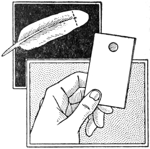
The device is made as follows: Procure a soft white feather from a fowl, and cut off the tip as indicated in the upper sketch. Cut a piece of cardboard, about 2 in. wide and 6 in. long. Fold it to form a folder, 3 in. long, and cut a hole, ¹⁄₄ in. in diameter, through both parts of it. Glue the tip of the feather between the folder at the hole, taking care that the fibers lie flat and that no rib is exposed. Glue the edges of the folder, and the device is ready for use. Hold the hand, or other object, to be examined about 15 in. from the lens, and place the latter close to the eye. Looking through the hole toward an electric, or other strong, light, it will be observed that the bones of the hand, for example, may be seen clearly. They will be outlined with a band of varicolored light. A frosted globe is better than one which exposes a filament.—Leander L. Droesch, Chickasaw, Ohio.
¶A safety-razor blade, fitted into a wooden handle, provides a convenient tool for ripping seams and cutting cardboard.
[413]
Bookkeepers and others who work close to a desk nearly all day find that unusual wear results on the front of the vest, forcing them to discard their suits sooner than would otherwise be necessary. By providing a strip of cloth of a color to match the goods of which the suit is made and buttoning it across the front of the vest from the lower to the upper button this wear is prevented.—J. A. McGrath, Hancock, Michigan.
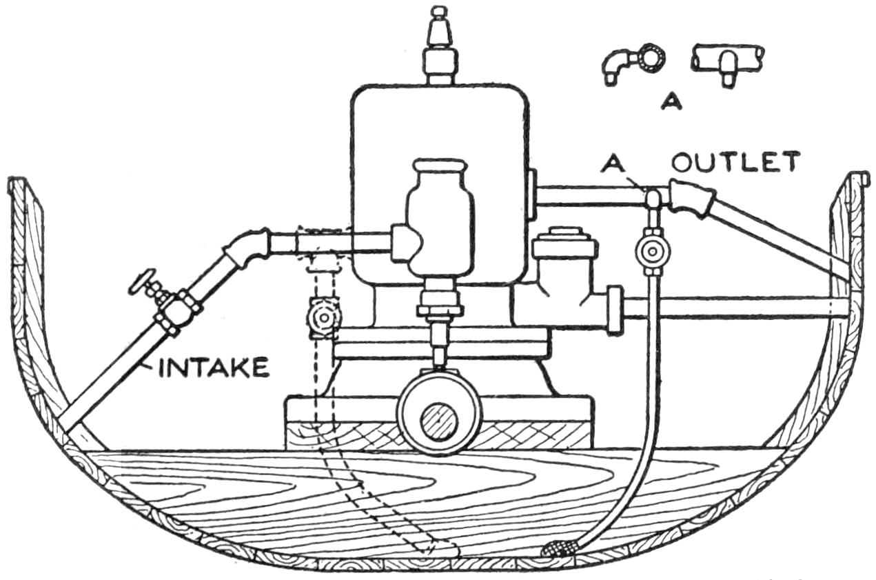
The Small Pipe Fixed to the Water-Jacket Outlet Siphons the Bilge Water from the Bottom of the Motorboat
The sketch shows a simple method of removing the bilge water from a motorboat automatically while the engine is in operation. A small pipe is fitted into the outlet from the water jacket, as shown at A, and extended to the bottom of the boat where the bilge water accumulates. A sack is fixed over the end of the pipe to prevent particles of dirt from entering the pipe. The water passing out of the water-jacket outlet causes a siphoning action in the small pipe, and the bilge water is drawn up and passes out of the larger outlet. At the left, in dotted outline, is shown a method of removing the bilge water by permitting it to be drawn up into the pump which supplies the water to the water-jacket. This method is sometimes used, but is satisfactory only when the bilge water can be kept clean, which is difficult.—Francis B. Dashiell, Baltimore, Md.
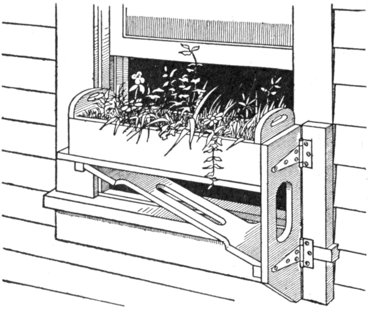
The Flower Box is Arranged to Swing Away from the Window so That It will Not Be in the Way
A window box arranged to rest in a hinged bracket on the outside of a window, as shown in the sketch, has advantages over the usual method of fixing the box permanently. The box is separate from the supporting frame and may be removed from it. The frame is attached to the window casing by means of T-hinges and is strongly supported by a bracket. When it is desired to clean the window, the device may be swung around and out of the way. This feature is also desirable when it is raining, for the flowers in the box may be watered conveniently in this way.—L. J. Hough, Toledo, Ohio.
Considerable smoke and dirt is caused by the burning of gasoline used to generate gas in starting a gasoline stove. This may be eliminated by keeping an oilcan filled with denatured alcohol convenient to the stove, and filling the starting pan with alcohol instead of gasoline. The spout of the oilcan is also convenient in pouring only a small quantity into the pan.—Spencer A. Pease, Chicago, Ill.
¶A strip of adhesive tape, fixed to the lower side of a straightedge used for cutting glass, will prevent it slipping.
[414]
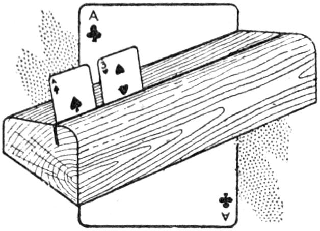
While disabled with a broken arm and being anxious to play cards for diversion, I was at a loss to hold my “hand.” I soon devised the card holder shown in the sketch, and found no difficulty keeping in the game. It is made of a strip of wood provided with a groove near the front edge, into which the cards are inserted.—W. E. Thomae, Milwaukee, Wisconsin.
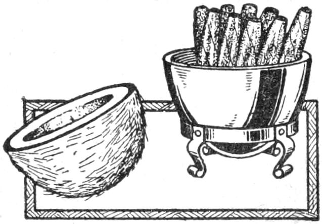
Trays for holding matches, or other articles, may be made of cocoanut shells by cutting them to appropriate sizes and smoothing the surface to a polish. The tray shown in the sketch was made in this manner, as were a number of match trays which were fitted with small sheet-metal dishes. The outside of the shell is first scraped as smooth as possible, sandpapered, and then oil-polished, producing a beautiful finish.—John F. Long, Springfield, Mo.
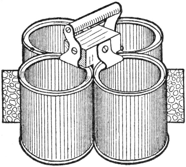
Four ordinary tin cans, fastened to a wooden block as shown in the illustration, make a serviceable and practical carrier for nails, staples, or similar materials, used in making repairs on the farm or in the shop. The tops of the cans are cut out carefully and the edges smoothed off so as not to injure the hand in removing nails from them. The tops are cut to the shape shown, as attached to the block and provided with a handle, making it convenient to carry the contrivance. If cans are used having covers which may be pried off, the central block should be extended and the handle nailed directly to it.—Dale R. Van Horn, North Loup, Neb.
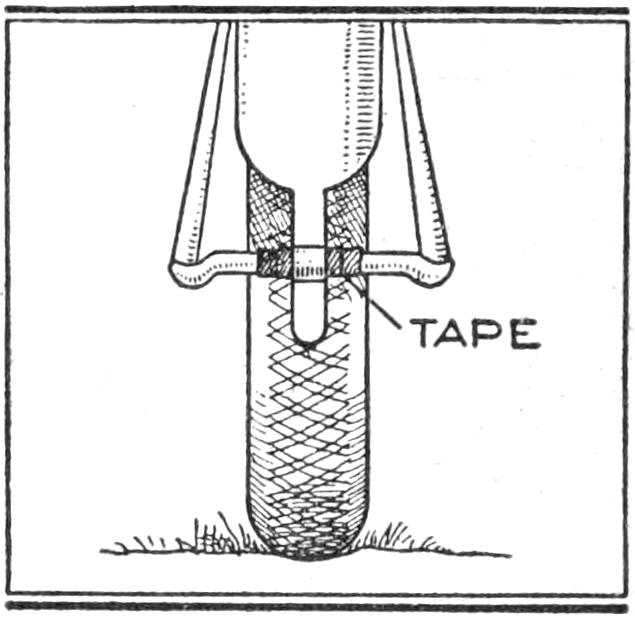
Annoyance while traveling over rough roads by the rattling of the rear stand on a motorcycle may be overcome by taping the part of the brace which hooks into a catch at the end of the rear mud guard. The sketch shows a view of the lower portion of the rear wheel with the stand raised and in place in the catch.
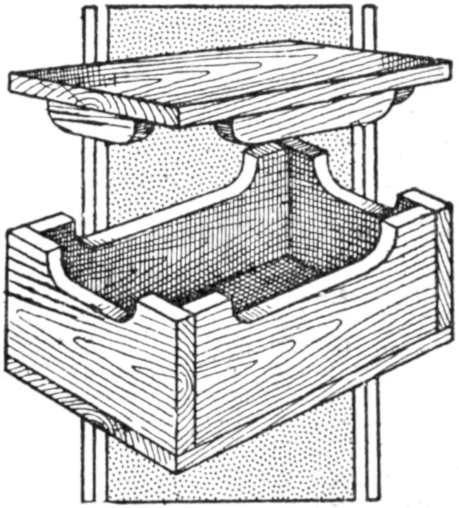
The box shown in the sketch is novel in that it provides a nonsliding cover with a minimum of wood for the construction and the use of no extra space for the lid. Where index, or other boxes must be provided in considerable numbers, or stored in a limited space, the saving will be worth while. Index cards, or other material, may fill the box to its upper level without hindering the availability of the cover. The small portions attached to the cover are cut from the side and end pieces.—DeWitt C. Ramsay, Bridgeport, Conn.
¶Small parts may be soldered conveniently by holding them with a clip made of a piece of clock spring.
[415]
A barometer that will indicate weather changes with reasonable accuracy may be made of two bottles. A milk bottle nearly filled with water is used as the container and a smaller bottle fitting snugly into the top is inverted in the mouth of the milk bottle. The mouth of the inverted bottle should extend about an inch below the surface of the water. Weather changes will cause the water to rise and fall in the neck of the inverted bottle.
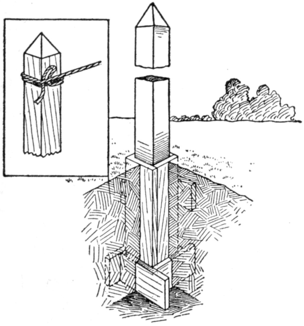
The Post may be Removed for Mowing the Court or When Not in Use
It is sometimes desirable to have tennis-court posts arranged to be easily removed from the lawn or the court when the grass is being mowed, or during the winter. The method of fixing the posts in the ground, as shown in the sketch, makes it convenient to remove the posts and still gives the necessary stability. A square wooden box, tarred to resist the moisture, is placed in the ground, and the post is fitted into it. The upper end of the box is level with the surface, and when the post is removed a wooden block is fitted into the opening. Removal of the posts permits the mowing of the grass close to them and leaves the place free from obstructions when the court is not in use.—Edward R. Smith, Walla Walla, Wash.
Amateur wireless operators often cannot afford to buy a lightning switch such as is required to ground the aerial when not in use. The sketch shows such a device, which was made of a marble slab fitted with copper strips cut from discarded half-tone plates. The base was smoothed and polished to the size indicated, 4 in. wide and 9 in. long. The upper edges were beveled off, and holes were drilled near the ends through which bolts were passed to fasten the small brackets supporting the crossbar.
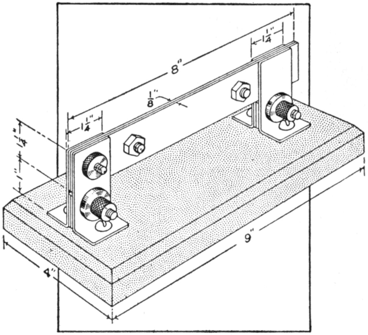
Discarded Copper Half-Tone Plates and a Piece of Marble were Used in Making This Lightning Switch for the Wireless Aerials
The copper pieces were made as follows: The plates of ¹⁄₁₆-in. copper were cut into strips, 1¹⁄₄ in. wide. Two were made 8 in. long; four, 3 in. long, and four, ⁷⁄₈ in. long. The 8-in. strips were fastened together with small bolts and a hole was drilled through one end of the joined pieces to fit the bolt which forms the pivot for the switch. The 3-in. strips were bent to form a ³⁄₄-in. angle, through which holes were bored for fastening to the base. The ⁷⁄₈-in. strips were clamped between the brackets at their lower ends to provide a slot for the crossbar. The bolts, by which the brackets were clamped together, were provided with binding nuts to which the wires were connected. A handle might be fixed to the crossbar, but this is not essential.
[416]
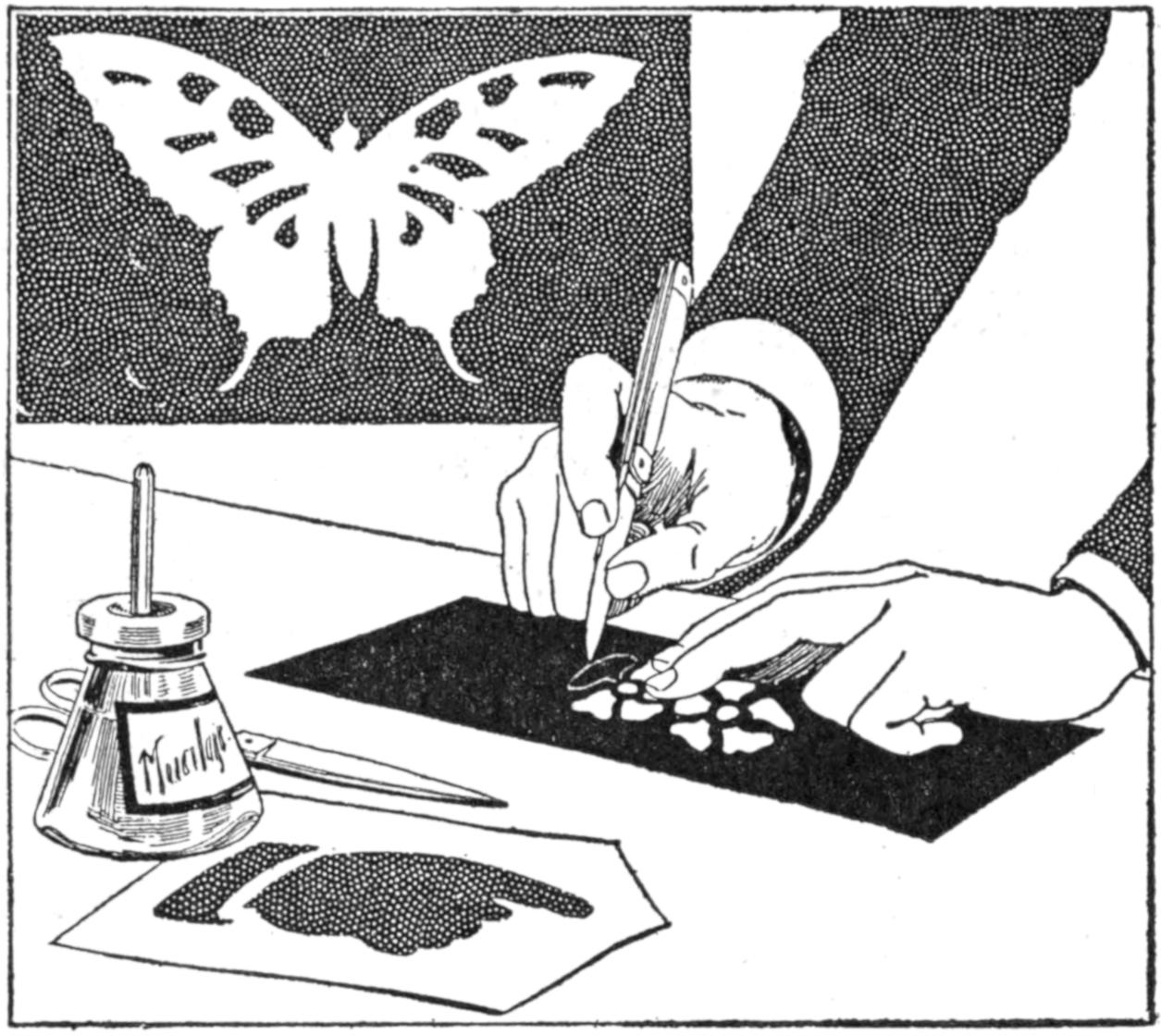
Serviceable Stencils may be Cut from Photographic Films, and Afford a Practical Means of Making Signs and Other Forms
Photographic films make excellent material from which to cut stencils for use in marking show cards, placards, etc., as well as for other uses to which stencils are put. Pictures, or other designs to be stenciled, may be pasted to the film and the outline cut, care being taken that the design is adapted for stenciling. This is important, since frequently binding strips must be left in the design in order to make it possible to cut a satisfactory stencil from it. The films are used with the rough side down, to prevent them from slipping. A variety of subjects for stencil design may be adapted from pictures clipped from publications or other sources.—Robert Smith, New Westminster, B. C., Canada.
For lighting the gas stove, matches are not only untidy but inconvenient. In lieu thereof I use a simple affair consisting of a wood handle with a large nail set in the end, with which it is only necessary to touch the burner in order to start a flame. There is nothing to wear out and no parts to renew. Furthermore this gas lighter uses only one wire—a fact that is apt to strike a person as being rather unusual on first thought. However, if the reader will connect one terminal of a 60-watt lamp with the gas main or to the gas stove and then touch the other terminal successively with each of the two ends of the live wires it will be found that the lamp will light up with one terminal but not with the other, for the reason that one side of the circuit is usually grounded at most electric-light plants as a precaution against lightning.
All that is necessary to get a spark is to provide a suitable resistance coil with an iron core, so that the fuse will not be blown and to secure sufficient inductance to get a hot spark. The writer uses an ordinary 50-ohm telephone induction coil, in which the primary and secondary are placed in series by the diagonal connection indicated in the sketch. Almost any coil or electromagnet of 25-ohm resistance, or more, connected in a circuit will prove safe and give a hot spark. Place the coil in some out-of-the-way corner, and run one strand of the usual flexible cord to the handle, which should be hung at some convenient point at the right-hand side of the stove. Let the handle itself be long enough so that there will be no tendency to catch hold of the metal point. Run the flexible cord through the center and out at the lower end, into which a wire nail with the head removed is driven. Solder the wire to the nail, and the lighter is ready.
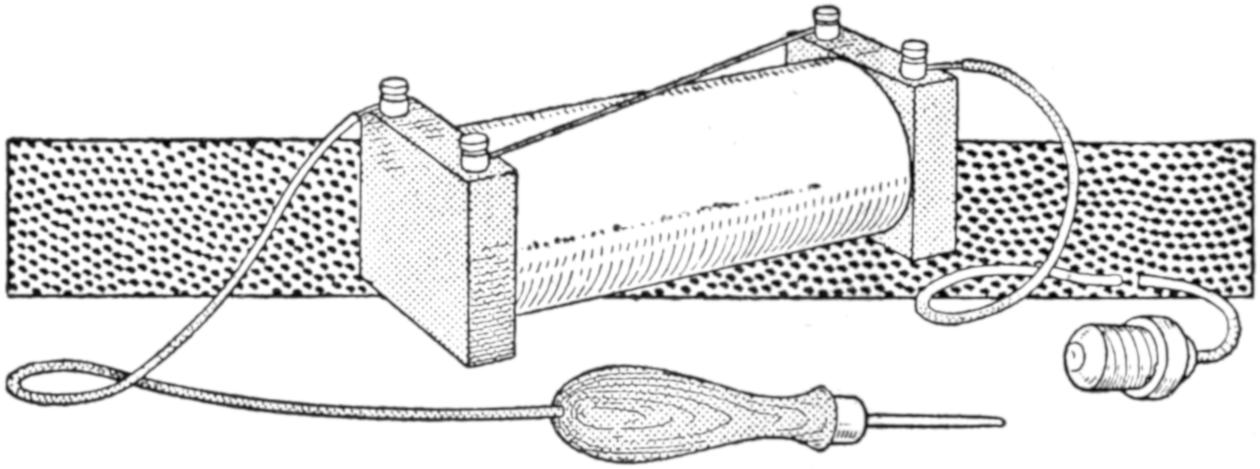
Single Contact Point for Making a Spark to Light a Gas-Stove Burner or Tip
For lighting Bunsen burners, and other fixtures using rubber tubing, a small wire may be run down the center of the tubing so as to ground the burner, or else a small surface on the workbench may be covered with tin and this grounded, so that it is only necessary to set the burner thereon to get a light.—John D. Adams, Phoenix, Arizona.
[417]
Annoyance from the rattling of windows may be overcome by attaching a small block to the side of the window casing so that it will engage the sash and hold it firmly. The block should be of ¹⁄₂-in. wood, about 3 in. long, 1 in. wide, and have one end rounded off. A screw is fixed through the block near the rounded end and driven into the window casing at such a point that when the block is turned upward on its pivot the rounded end will act like a cam and force the sash firmly against its grooves.
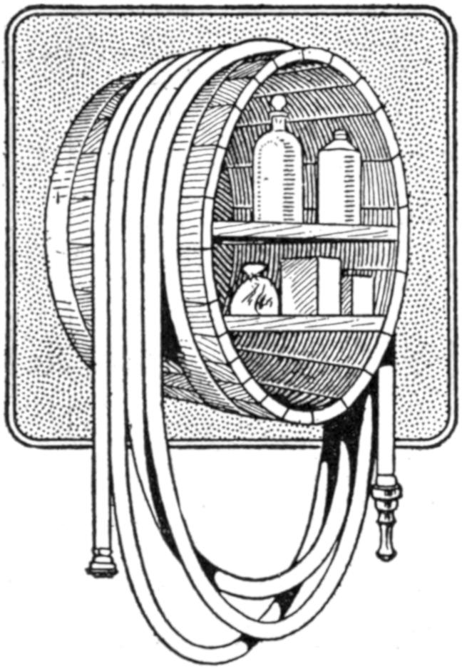
Care in the storage of a garden hose will pay the owner in the longer life of it, and the homemade bracket shown in the sketch suggests a convenient method of caring for the hose. A portion of a barrel was sawed off at one of the hoops, and after reinforcing it by nailing the hoops and inserting shelves, it was nailed to the wall. The hose may be coiled over it in shape to be easily carried to the lawn or garden, for use. The shelves provide space for an oilcan for the lawn mower, and other accessories.
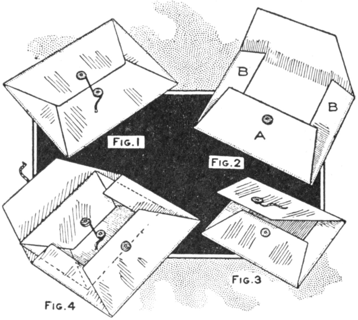
Fig. 1 Fig. 2
Fig. 4 Fig. 3
Folders Like That in Figure 1 may be Glued to Form Envelopes, Figure 2, or Cut Down to the Size Shown in Figure 3, for Use in Combination, Figure 4
Folders in which large cards, calendars, posters, etc., are commonly mailed may be utilized to make convenient filing cases. Envelopes of the type shown in the sketch, with leatherboard and cord fasteners for holding the flaps together, may be cut to a uniform size or used in any smaller size desired, and, by gluing the flaps A and B, will provide serviceable containers. Small tools or other objects likely to injure a single-thickness folder, or drop out of it, may be stored in double envelopes made in this way.
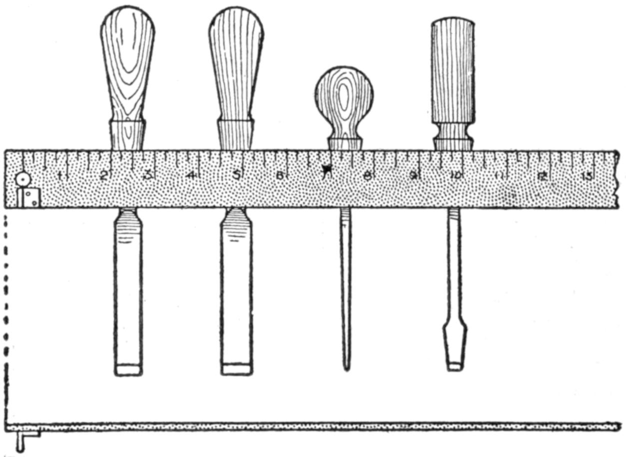
The Brass Plug and Angle Are Convenient Additions to the Yardstick, Which Forms the Front of the Tool Rack
I have derived considerable satisfaction from the use of a yardstick fitted above my workbench. A plug of brass, having a center-punch mark, was inserted at the zero point on the yardstick. This is convenient in setting dividers and other instruments. Below the plug was fixed a small brass angle, set so that its inner face was at the zero point. This is useful in measuring pieces from a finished end. If the end of the yardstick is at the zero point it is necessary to attach a small extension to take the brass plug.—V. A. Rettich, Hollis, N. Y.
[418]
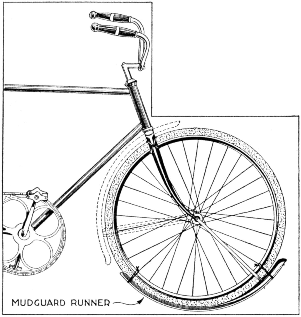
The Mudguard is Fastened to the Rim of the Wheel and Acts as a Runner over Ice and Snow
A bicycle may be used with satisfactory results in winter by arranging a runner under the front wheel, which is lashed to the fork as indicated in the sketch. The mudguard is used as a runner by releasing it and dropping it to the position shown. It is then tied securely to the rim of the wheel and the wheel is tied at the top to the fork. This idea may be adapted by providing a special runner of sheet metal, making it unnecessary to wear the mudguard.—C. H. McCaslin, Portland, Ore.
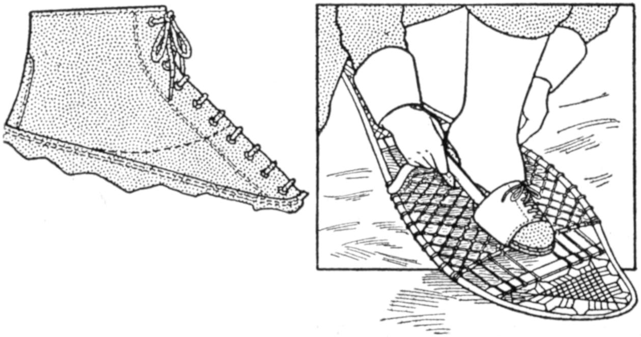
The Uppers of an Old Pair of Shoes were Used to Make a Set of Toe Clips for Snowshoes
The uppers from a pair of worn-out shoes may be made into a serviceable set of toe clips for snowshoes by cutting them off, as shown in the sketch, and fitting them to the lacing of the snowshoes. The clip is fastened in place by passing the tying strap through slots in the former, under the lacing of the snowshoe, and then around the ankle in the usual manner of fastening.—Richard F. Lufkin, Dorchester, Mass.
Tracings mounted on muslin will give long wear and are more satisfactory in handling than the unmounted drawings. The method of mounting them is as follows: Stretch a piece of starched muslin, slightly larger than the drawing, on a flat, smooth board, fastening it with tacks. Coat the back of the tracing with a good varnish, and place it, face down, on a flat surface so that it may partly dry and become tacky, which usually takes two hours. Place the tracing upon the stretched muslin, varnished side down, and place a smooth sheet of wrapping paper over it. Using a moderately warm flatiron, and beginning at the center of the tracing, iron toward the edges, applying moderate pressure. To remove the tracing from the cloth, it is necessary to warm the cloth with the iron and strip the tracing and cloth apart gradually.—John W. Grantland, Cincinnati, Ohio.
The woodwork of small electrical or experimental machines and devices often detracts from the workmanship because proper care is not taken in finishing the edges. To smooth off the ends of a small baseboard squarely, proceed as follows: Square up a piece of 2 by 4-in. stock, 1 ft. long; place a flat sheet of sandpaper on the bench and set the 1-ft. block on top of it, holding it in place with the left hand. Hold the piece to be squared up firmly against the block and rub it on the sandpaper. A square edge of smooth finish will result. The edges should, of course, be planed as smoothly as possible before sanding in this way.—John D. Adams, Phoenix, Ariz.
[419]
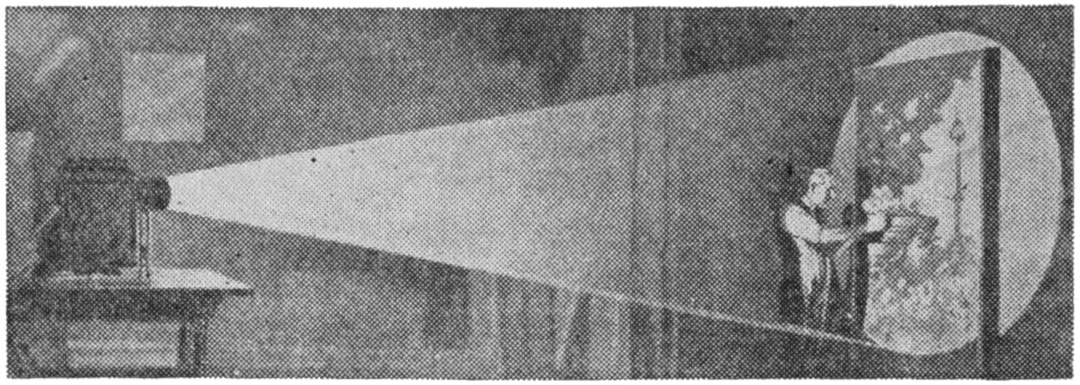
Scenery for an Amateur Theatrical Performance was Made by Painting Outlines Projected from a Lantern
Scenery for a home-talent theatrical performance was required, and since the services of an expert in that line were not available, an interesting method of obtaining satisfactory sketches for the figures and other objects in the background was devised. Colored lantern slides of scenes suitable for the purpose were selected and projected upon the canvas to be painted, as shown in the illustration. The outlines were drawn around the projected figures, making them as accurate as the original, and far better than would have been possible otherwise by an amateur painter. The colors were applied following the original model, with satisfactory results. By the use of various portions of slides, it was possible to place figures and outdoor effects on the background which was obtained from the first slide used. A factor which must be considered in using this method is that the picture on the canvas will be reversed as to right and left positions compared with the original, if a direct-reflection projector of the type used with post cards is employed.—Thomas R. Milligan, Fort Worth, Texas.
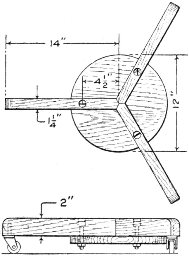
A convenient truck for handling heavy objects, especially in the home where commercial devices for this purpose are not available, is shown in the illustration. It consists of a frame built up of three 1¹⁄₄ by 2 by 14-in. strips, fixed to a disk, ⁷⁄₈ by 12 in. in size. Revolving casters are mounted under the ends of the arms, giving great freedom of movement in transporting loads. The three-caster arrangement is better than the use of four casters, because it accommodates itself to irregularities in the floor.—Armydas E. Sturdivant, Muncie, Ind.
¶The burner of an acetylene bicycle lamp, fitted to an ordinary gas jet, will produce a very hot flame.
It is frequently necessary that typewritten insertions or corrections be made in papers which have been typed and bound, usually by rivets along the top edge. It is difficult to remove the rivets and replace them satisfactorily. To make such insertions, feed a blank sheet of paper into the typewriter until its feeding edge is even with the upper edge of the guide fingers. Then insert the bottom edge of the sheet on which the correction is to be made, underneath the sheet already in the machine; reverse-feed the sheet to be corrected into the typewriter. Corrections may then be made in the usual manner.—A. J. Cook, Pittsburgh, Pa.
A tire pump actuated by the explosions in the cylinder of an automobile engine, and made of materials easily obtainable, is shown in detail in the illustration. A section of iron pipe of a diameter to fit one of the ports, and about 4 in. long, as shown in Fig. 2,[420] is provided with a reducer, a tee, and two caps. The inside of the pipe is turned up true in a lathe and fitted with a piston, the head for which is shown in Fig. 1. The head is built up of a wooden drum, washers, and leather packing disks. The washers should be slightly smaller in diameter than the chamber, and the leather disks make it air-tight.
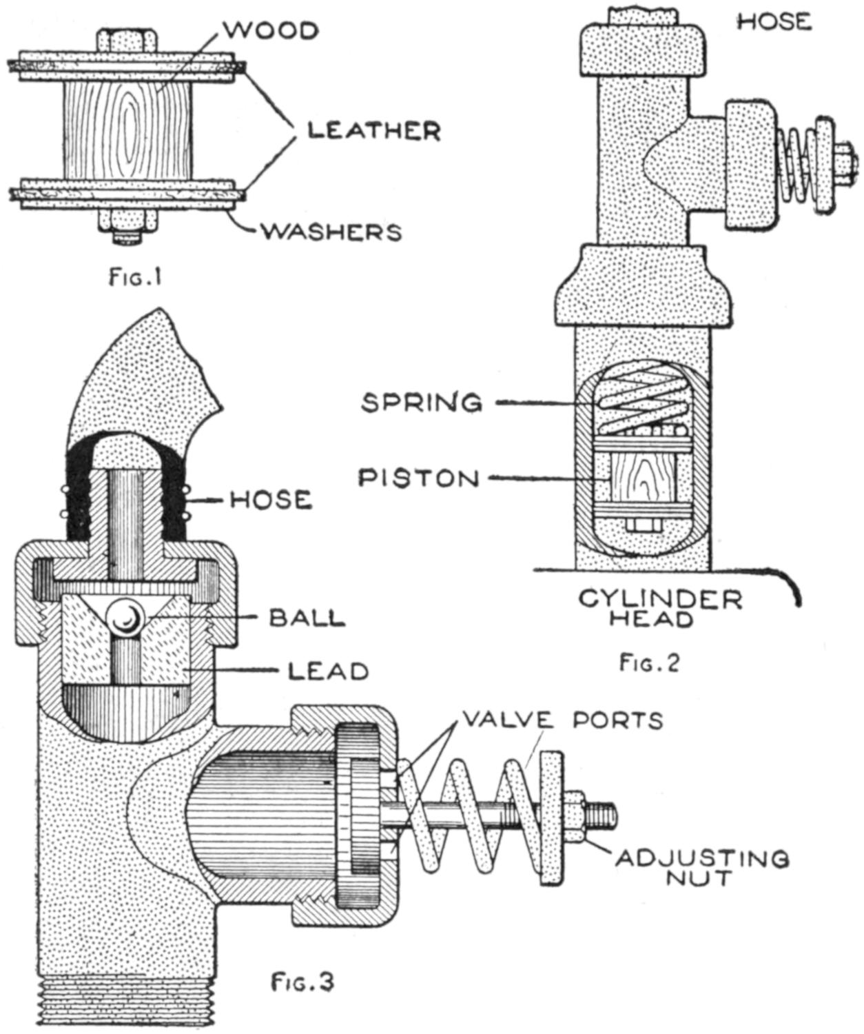
Fig. 1
Fig. 2
Fig. 3
Automobile Tires may be Inflated Quickly by the Use of This Homemade Pump
The tee is provided with two valves, as shown in the detail sectional view, Fig. 3, the upper ball valve retaining the pressure in the pipe line, and the other valve admitting air above the piston. The ball valve has a seat of lead, and a ribbed fitting is fixed to the pipe cap above it, to provide a fastening for the hose. The cap of the other valve is fitted with a spring, adjustable on a threaded pin.
A light spring fixed to the upper side of the piston, as shown in Fig. 2, forces the piston back to its lower position after the force of the explosion in the cylinder has acted upon it. The cylinder of the pump should be oiled, and a reinforced rubber hose should be used to conduct the air under pressure to the tire.
The operation is simple: The initial stroke of the engine cylinder draws the piston down, bringing in a charge of air from the valve ports at the side of the tee; the following compression and explosion strokes drive it back, forcing the air out of the ball valve, as the other valve closes on the upstroke of the piston. A large tire may be pumped up with this device in from five to ten minutes.
When a number of cards or sheets are to be ruled with either horizontal or vertical divisions, the following method will be found a timesaver: Rule one of the cards as a sample. Place it on the drawing board with its lower edge set against two thumb tacks driven part way in. Rule extensions of the lines on the card to a sheet of paper fastened to the board under the card. Set a third thumb tack at the right edge of the card as a guide. By placing the cards to be ruled against the three thumb tacks in the position of the original card, the rulings may be made quickly with the marks on the paper backing as guides.—W. P. Shaw, Stratford, Can.

The Strip is Cut into Squares Which are Folded and Driven into the Support, Binding the Wire
Inexpensive and practical staples for binding wires used in bell circuits, or for similar purposes, may be made from a strip of tinned sheet metal, about ¹⁄₂ in. wide. The strip is cut on the sides, as indicated in the sketch, and the squares are broken off as needed. They may be bent quickly to the shape shown, and are used by placing them over the wire and driving the points into the wall or other support. If properly made, they will not injure the covering of the wire and are more satisfactory than wire staples.
[421]
Ordinarily heavy pieces of sheet asbestos are used for the mats placed under hot dishes on the dining table. These are easily broken if bent, and a simple method of overcoming this breakage is to make mats as follows: Cut two pieces of sheet asbestos, each about one-half the thickness of that usually used, one having about ³⁄₄ in. around the edge which may be used as a binder in pasting the sheets together. Cut notches into this edge, at intervals of about 2 in., and insert a disk of wire window screening between the pieces of asbestos. Turn the edges of the larger piece over and paste in place.
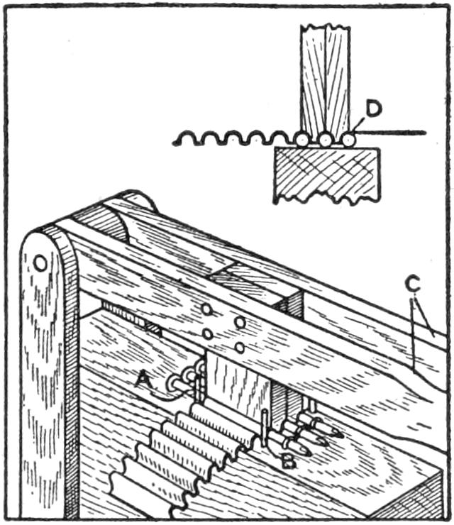
Having a sheet-metal cog rail to make for the adjusting mechanism of an enlarging screen, I built a cog-forming device as shown in the sketch. A block of wood served as the case and two levers with hinges were fixed to one end of it. Two pieces of hardwood were grooved at their ends as shown in the smaller sketch, to fit over three tenpenny nails, A, held in place on the block by staples. Four small nails, B, were set into the block, as shown, to act as guides for the strip of metal, which was fed between the forming blocks and the nails on the case. By pressing down on the hinge levers, the strip was formed into corrugations or teeth. In order to make the teeth uniform it was necessary to guide the forming pieces by having one of the cogs fit over the first nail. The strip thus formed was fixed to a wooden piece and served as a cog rail.—R. E. Henderson, Walla Walla, Washington.
An excellent pair of leggings for use in brush and forest land can be made in a few minutes from birch bark cut in the woods. Select a suitable tree, about 6 or 8 in. in diameter, and cut into the heavy bark to obtain two rolls around the circumference of the tree, taking care not to cut deep enough to injure it. Fit these sections around the legs leaving 6-in. portions overlapping. Trim the bark to the proper shape and soak it in water to soften the grain. Place the bark close to the fire until it curls. The leggings are then ready for use.
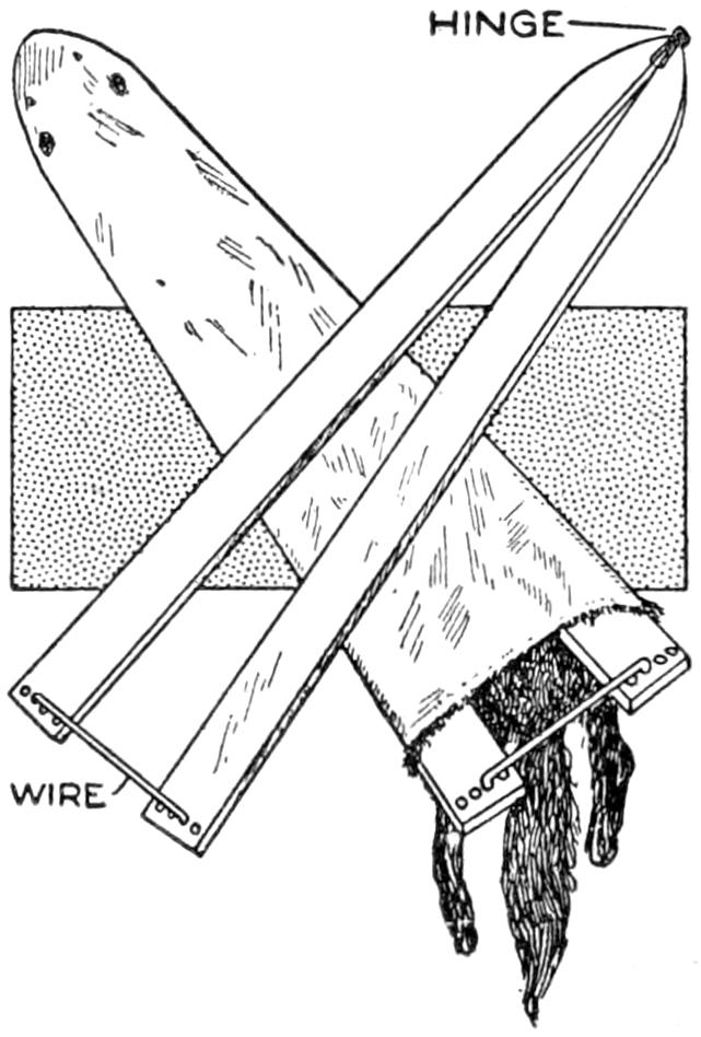
Small hides should be dried over a stretcher to give the best results, and the device shown in the sketch will be found useful for this purpose. It is made of two strips of ¹⁄₂-in. wood, hinged at the pointed end. Small holes are drilled into the upper surface at the other ends and adjustment is made by means of a wire bent at the ends and inserted in the holes.—Elmer Tetzlaff, East DePere, Wis.
¶Wire mesh is useful for drawer bottoms in tool cases where dirt is likely to accumulate.
[422]
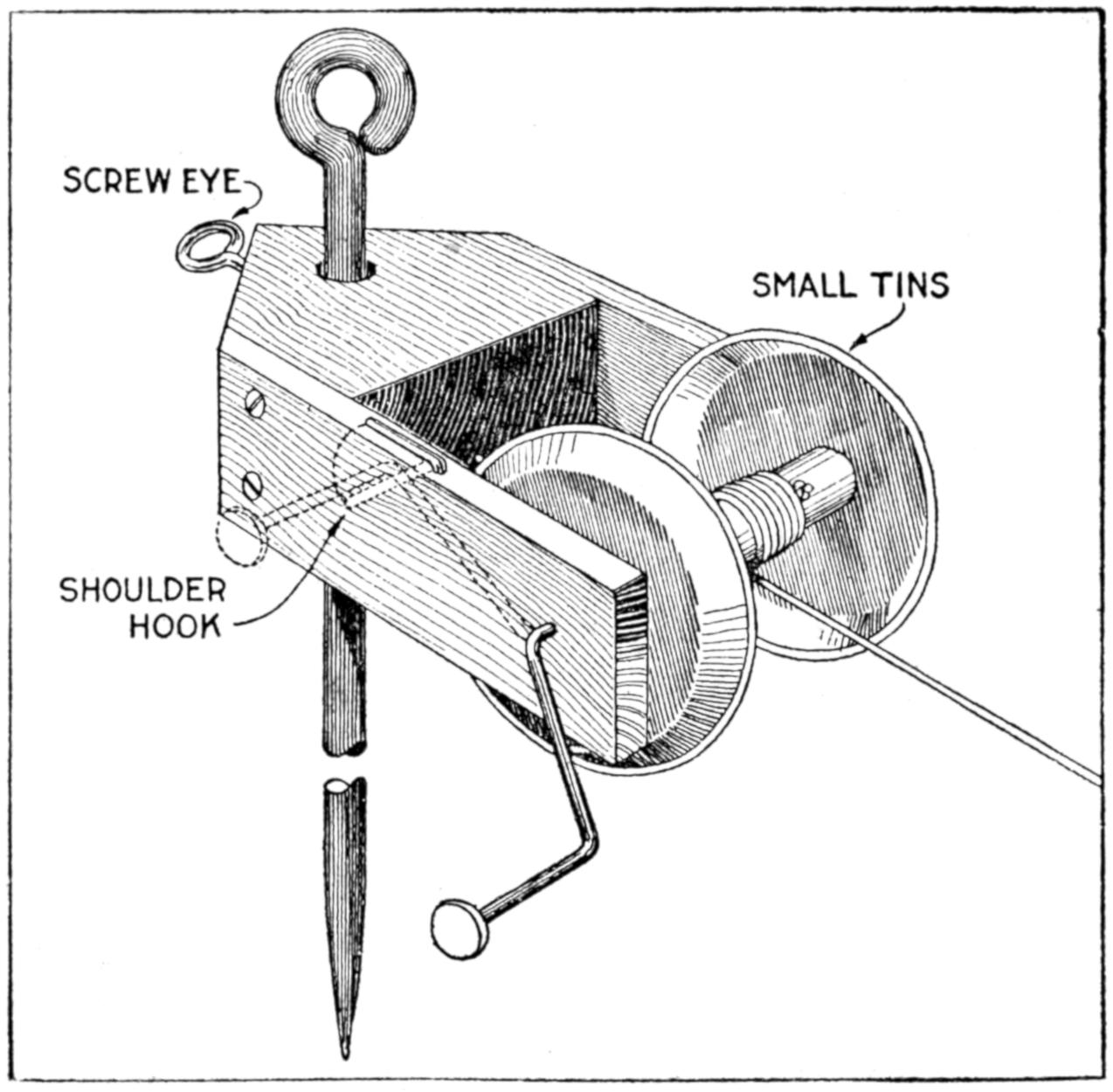
This Reel Aids in Setting Out Plants in Rows
Many gardeners derive as much pleasure from the orderly arrangement of the plants in their “farms” as from any other feature of this home diversion, and I am one of them. In order to facilitate the planting I made a reel like that shown in the sketch. The frame is of wood, and the reel is made of a piece of broomstick to which two small tins, or box covers, are nailed. A wire handle made of a long nail is fitted to one end, and a shoulder hook is used as a stop for the handle when it is desired to check the line. A screw eye driven into the back of the frame holds it at various heights on the stake. This device is far superior to the common use of two stakes for the planting cord.—James M. Kane, Doylestown, Pennsylvania.
Deriving long use from an umbrella depends in part on proper selection, care of the cloth and frame, and precautions against loss or theft. A silk cover is desirable to shed rain, and a cotton one for a sunshade. The hot sun dries out the silk and heats the metal ribs under it, quickly destroying it. If silk is used for sun protection, wet the cover occasionally. Always set an umbrella to dry, handle down if there is not space to dry it open.
A broad ribbon loop on the handle of a woman’s umbrella permits carrying it on the wrist and prevents forgetting it. An umbrella with a removable handle can be folded into a suitcase, and putting the handle in the pocket when leaving the umbrella in any public place makes it less liable to theft. An umbrella should bear the name and address of the owner.
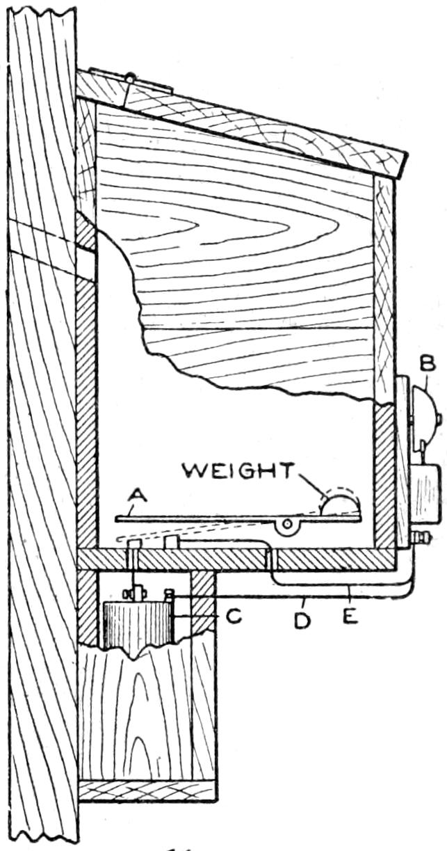
The annoyance of watching for the arrival of the mailman was overcome by the fitting of an electrical alarm to the mail box, as shown in the sketch. A strip of metal, A, was pivoted in the box and weighted on one end. A bell, B, was wired to dry cells in the box below the container for the mail. When the mail is dropped in the box the end A is forced down, forming an electrical contact and completing the circuit from the cells C through the wire D and back through the wire E. When the mail is removed the weight raises the metal strip.—James E. Noble, Portsmouth, Canada.
An ordinary compass, fitted flush in a wooden frame as shown in the sketch forms the basis for the polarity indicator described. The N, or north, and S, or south, points of the compass should run lengthwise with the frame with the former on the end farthest from the binding posts, C and D. Five turns of No. 18 gauge, or any similar wire are wound lengthwise around the frame and over the compass. The ends of the wires terminate at the two binding[423] posts. Begin at C and wind toward the compass, binding the wire at D.
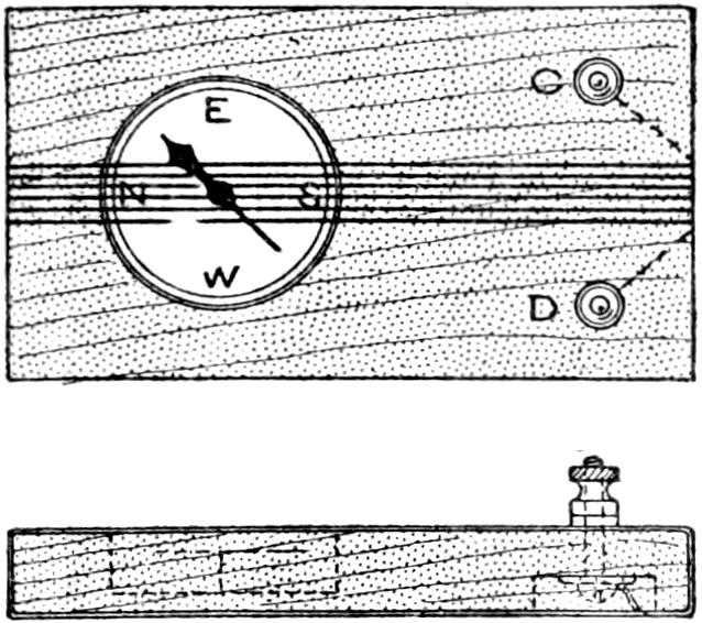
If the two ends of a wire are free, and it is desired to know whether there is any current present, and if so, its polarity, fasten one wire to the post C and the other to D. Before connecting the wires, hold the compass and frame in such a way that the needle is over the N point on the compass dial. If, after the wires are connected, the needle moves, there is a current flowing. If the needle is deflected toward the east, the negative wire is on C; if it is deflected toward the west, the positive wire is on C.
When it is desired to ascertain the polarity of a wire, which is covered by a floor, ceiling, or molding, hold the compass as explained, and either directly above or below the wire. Then turn on the current. If the instrument is above the wire, the wire extending parallel with it north and south, and the needle is deflected toward the west, the current is flowing from the north to the south end of the wire. If the wire runs east and west and the needle is deflected to the west, the current is running from west to east.
If the wire runs on a diagonal between the directions mentioned, and the needle is deflected toward the west, he current is flowing from the quadrant between N and W on the compass dial toward the quadrant between S and E. If the instrument is held over the wire and the needle is deflected toward E, the polarity is the opposite to that last indicated. Should the instrument be held below the wire, if the needle goes toward W, it is equivalent to going toward E when above the wire.—H. Sterling Parker, Brooklyn, New York.
¶If the white of an egg is used to seal an envelope which has no mucilage on the flap, it cannot be opened by steaming it.
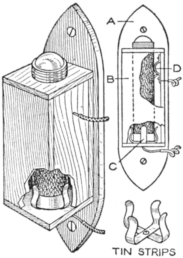
To save groping about in the dark for my flash light when suddenly awakened in the night, I devised the arrangement shown in the sketch and by which a “flash” is used as a wall night light, without lessening its common uses. The holder B and the board A are of wood, and into the box is fitted a metal clip, C, to hold the light. A round hole of proper size is cut through the top of the box and the light set through it so that the bottom end rests in the clip, the tin ferrule pressing against it firmly. A light spring, D, makes contact with the upper terminal of the push switch without closing it. The apparatus is fastened to the wall, and insulated wires, soldered, one to the clip C, and the other to the spring D, are connected to a switch placed in a convenient position. This switch replaces that on the light. The ceiling serves to reflect and distribute the light rays.—B. L. Dobbins, Harwich, Mass.
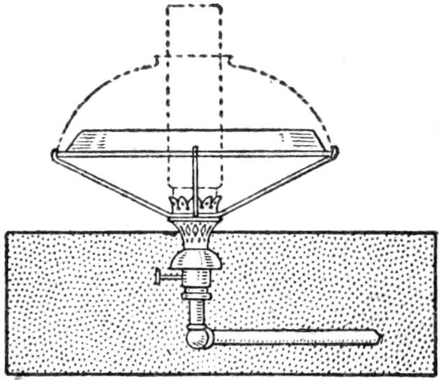
A satisfactory gas heater to take the chill out of the air in a small room by fitting a pie plate over a gas burner was made by me, as shown in the sketch. The wires which formerly held the glass shade were fitted into holes punched in the rim of the plate. It could thus be removed quickly when not needed and the glass shade put back in place.—Morris Tinsky, Chicago, Illinois.
[424]
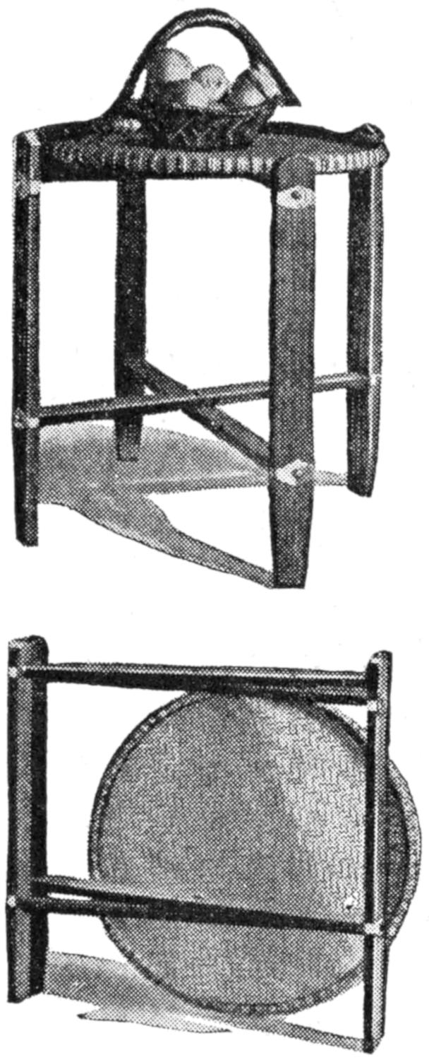
A folding table frame, designed as a support for a circular split-bamboo tray, is shown in the photographs reproduced and detailed in the working drawing. It is a serviceable and inexpensive piece of furniture, and can be constructed readily by the home mechanic. As the trays vary in size, the frame must be made to correspond, those from 24 to 28 in. in diameter being satisfactory. The tray may be made by the ambitious craftsman or purchased at stores dealing in Oriental goods. A wooden top may, of course, be substituted. The frame is made preferably of soft wood. The following finished pieces are required for a 24-in. tray: 4 legs, ⁷⁄₈ by 3 by 30 in.; 4 crosspieces, 1 by 2 by 25 in. Mortise the legs to the ends of the crosspieces, one set of mortises being ⁷⁄₈ in. below the other. Assemble the parts and fasten the joints with glue and 2-in. flat-head screws, countersunk.
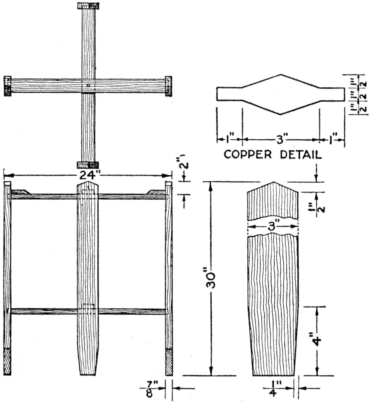
This Tray Table Is Readily Portable, and Useful in the House and on the Porch or Lawn
Adjust the crosspieces of each set so that their centers match, and fasten them in this position with screws, from the under side. The two parts of the frame revolve on them when the table is “knocked down.” On the ends of the lower crosspieces of each set, fasten blocks to level the support for the tray. Finish the frame to harmonize with the furniture of the room. Conceal the screw heads under bands of hammered or oxidized copper, fastened with copper or brass pins. A second tray may be placed on the lower crosspieces.—F. E. Tuck, Nevada City, Calif.
Those who wish a small desk light that may be pushed back out of the way in the daytime, will find the accompanying sketch of interest. When in use on a roll-top desk, the lamp is placed on top near the edge, so that the bulb overhangs. A 25-watt lamp will light the bed of the desk, and the small metal shade is so placed that no part of the bulb is visible to the eye of the worker. By providing a suitable base, the lamp may be adapted to other uses. A stock paper weight, about 2 in. in diameter and covered with green felt, was used as a base. An ordinary drop-cord socket is provided, and to one side of the top cap a strip of brass, ¹⁄₁₆ by ¹⁄₂ in., is soldered. A hole is drilled near the end of this strip so that the screw which holds the knob will also hold the socket. Connect the flexible cord in the usual manner.
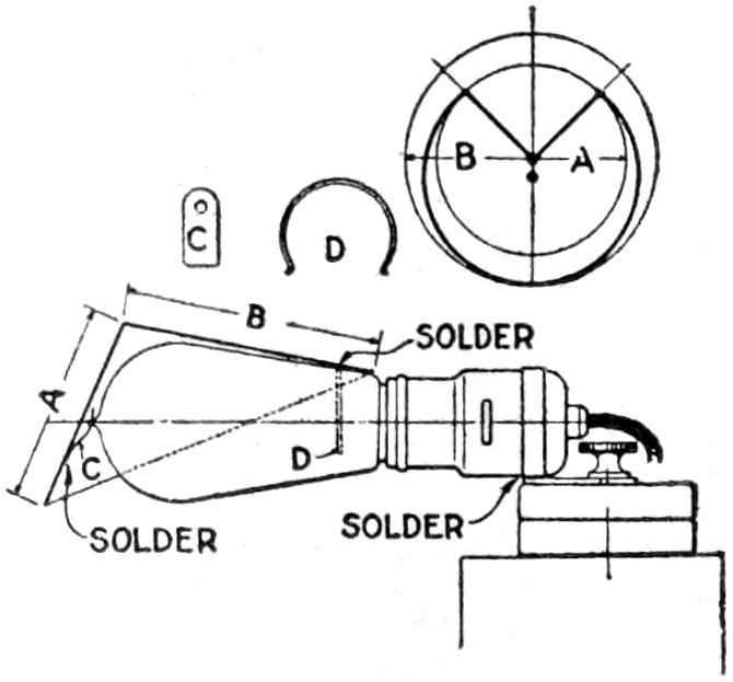
The shade is made of sheet metal,[425] bent in the form of a cone, having the front shorter than the opposite edge. Make a sketch of the bulb, and determine the lengths of the two sides A and B, and then draw two concentric circles of corresponding radii on paper, as indicated in the small diagram. The proper curve for the shade will then lie between these two circles. Cut a paper pattern, and form it into a cone. After the proper shape is determined, mark it on the metal, cut it to shape, and solder it. A small spring clip, C, engages the tip of the bulb; the back of the shade is held by a piece of spring wire, D. It is easy to spring the shade off in replacing the bulb. The outside of the shade should be enameled an olive-green.—John D. Adams, Phoenix, Arizona.
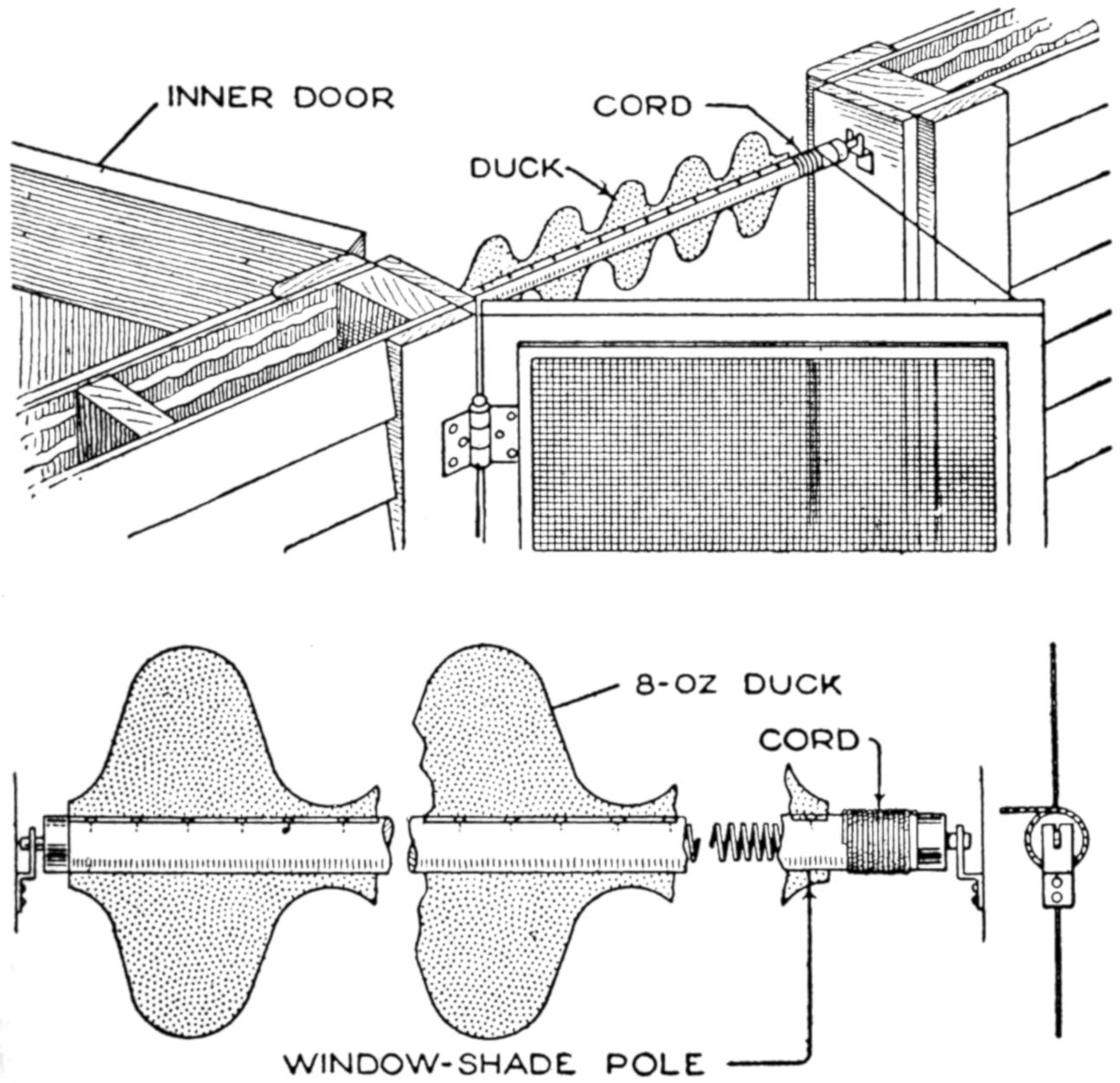
The Scalloped Roller is Revolved Rapidly When the Door is Opened, Frightening Flies
An effective means of frightening flies away from a screen door may be made from a spring curtain rod and cotton duck. Scallops of 8-oz. duck, 6 in. long, are fastened to the pole, on opposite sides, as shown. The ratchet on the end of the pole is arranged so as not to catch. A small cord is wound around the pole and fastened to the screen door. The rod supports are fixed near the top of the door frame.—Josef H. Noyes, Paris, Tex.
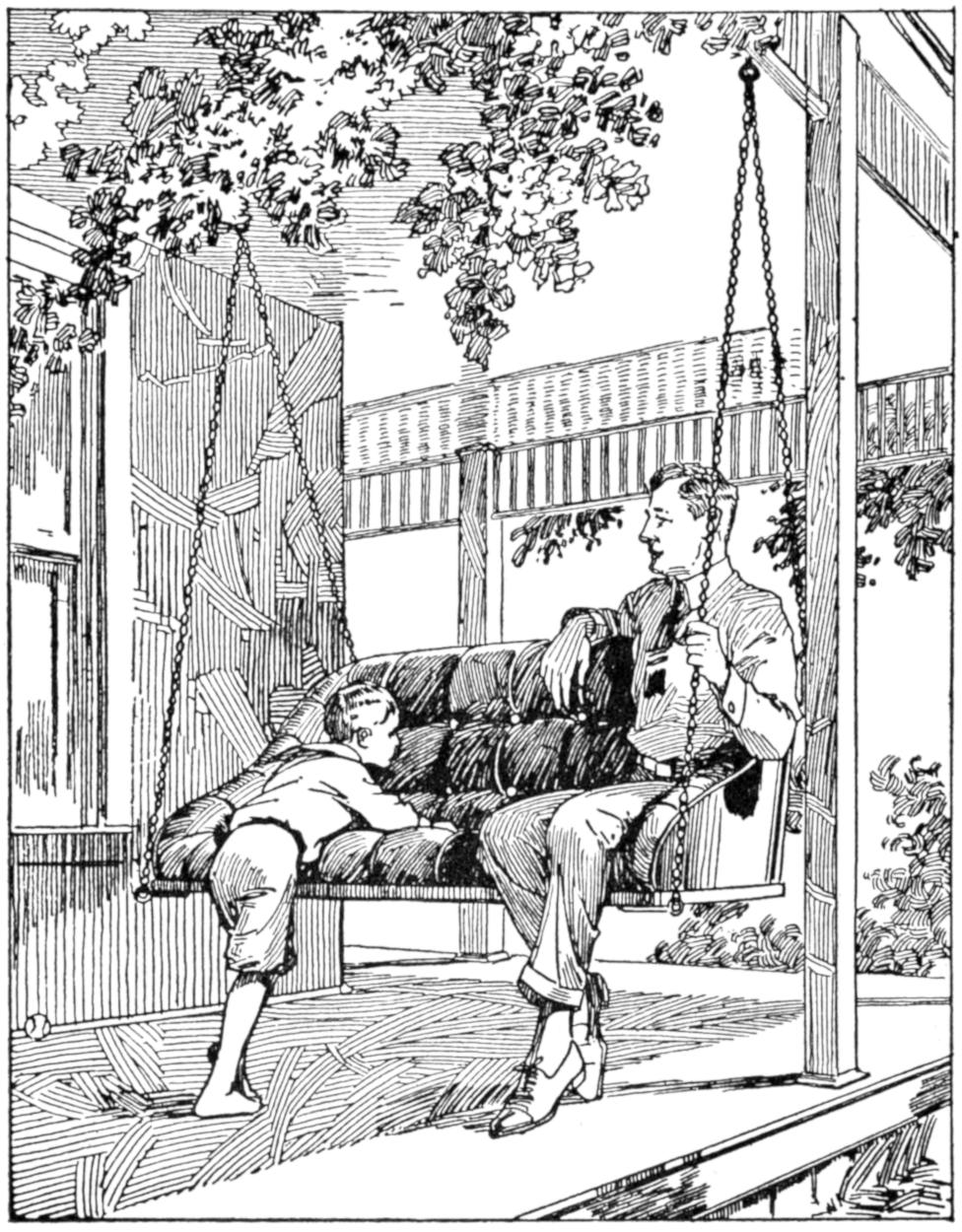
The Seat Discarded from a Rebuilt Car was Put to Good Use
When an obsolete type of automobile was converted into a truck for marketing purposes, a leather-upholstered seat, discarded, was utilized as an attractive and comfortable porch swing. Hooks were secured to the front corners of the seat and to the upper edge of the back, for the chains attached to suitable supports.—George L. Ayers, Washington, D. C.
A strong packing box was converted into a useful and not unsightly chest by covering it with panels of linoleum left over from a job of covering a floor. Strips, ¹⁄₂ by 2 in. wide, were nailed around the corners of the box to form a panel on the top, sides, and ends. The wood and the linoleum were shellacked, and made a good appearance.
¶The lower corner of an envelope may be used as a small funnel.
[426]
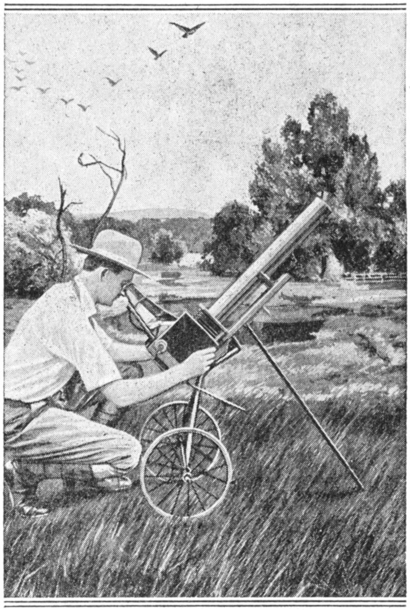
Bird Images Large Enough to Show Identification Markings are Obtained with This Camera
A reasonably large image must be obtained in photographing bird life, or the details of plumage and identification are lost, reducing the value of the pictures. The “gun camera” shown in the photograph was devised for this purpose, and with it exposures may be made more quickly than with the telephoto type of camera, a feature of great value in this class of photography. The device consists of an ordinary reflecting-type camera, mounted on a carriage for ready portability and quick adjustment. The bellows is supplemented with a tube, permitting the use of lenses of upward of 30-in. extreme focus. This gives a larger image without loss in speed. A ¹⁄₄-in. image of a bird was obtained with a 7¹⁄₂-in. extreme-focus lens, as against a 2-in. image with one of 30-in. focus, from the same position. The lens is set near the rear end of the tube, giving a deep hood for shading the sunlight. Lenses of an old type, known as “Long Toms,” were used. They are inexpensive compared with newer types with iris diaphragms, and give good results even at ¹⁄₁,₀₀₀ exposures.—Arthur Farland, New Orleans, La.
The electric fan is useful not only for cooling the air in summer, but also for distributing the warm air to advantage in the winter. An efficient way of warming a room fairly uniformly is to place an electric fan near a radiator, so that its breeze passes through the heating coils, or near another source of heat. The heat is circulated around the room, instead of being kept in a limited area.—Peter J. M. Clute, Schenectady, N. Y.
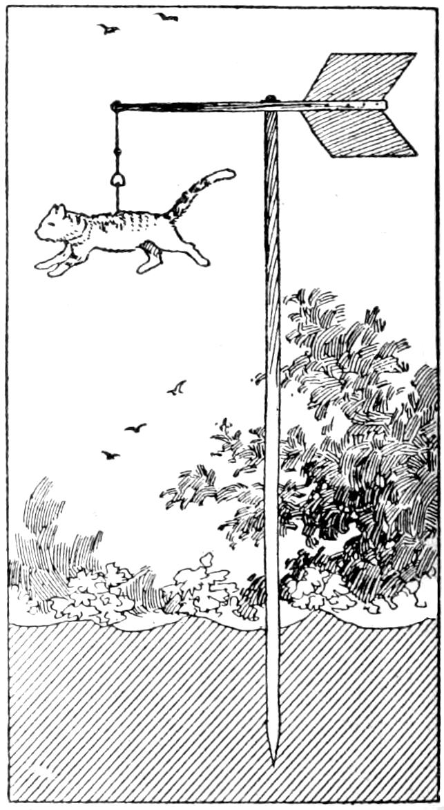
A scarecrow resembling a living animal is often more effective than other devices, and the cat-and-bells arrangement shown in the sketch was found especially so. The hide of a cat was stretched over a hollow frame and suspended by a cord from a large weather vane. Several bells were attached to the cord, and when the vane shifts in the wind, the movement of the hide and the rattling of the bells combine to frighten the birds.—F. H. Sweet, Waynesboro, Va.
¶A coating of five parts of coal tar, one part gasoline, and one part japan drier will make canvas nearly water-tight.
[427]
Considerable power and speed can be developed under ordinary water-supply pressure by the turbine, or water motor, shown in the sketch and detailed in the working drawings. The parts are of simple construction, and the machine may be assembled or taken down easily. It is useful for either belt or direct connection to electrical generators, small machines, etc., the direct connection being preferable for a generator. The wheel is built up of sheet metal and provided with curved buckets set in the saw-tooth edge. The water is admitted through an opening in the lower part of the housing and passes out at the opposite end into a suitable drain pipe. The housing is made of two sections, the main casting and a cover plate. Bearings for the shaft are cast into the housing, which is reinforced on the back by ribs radiating from the center.
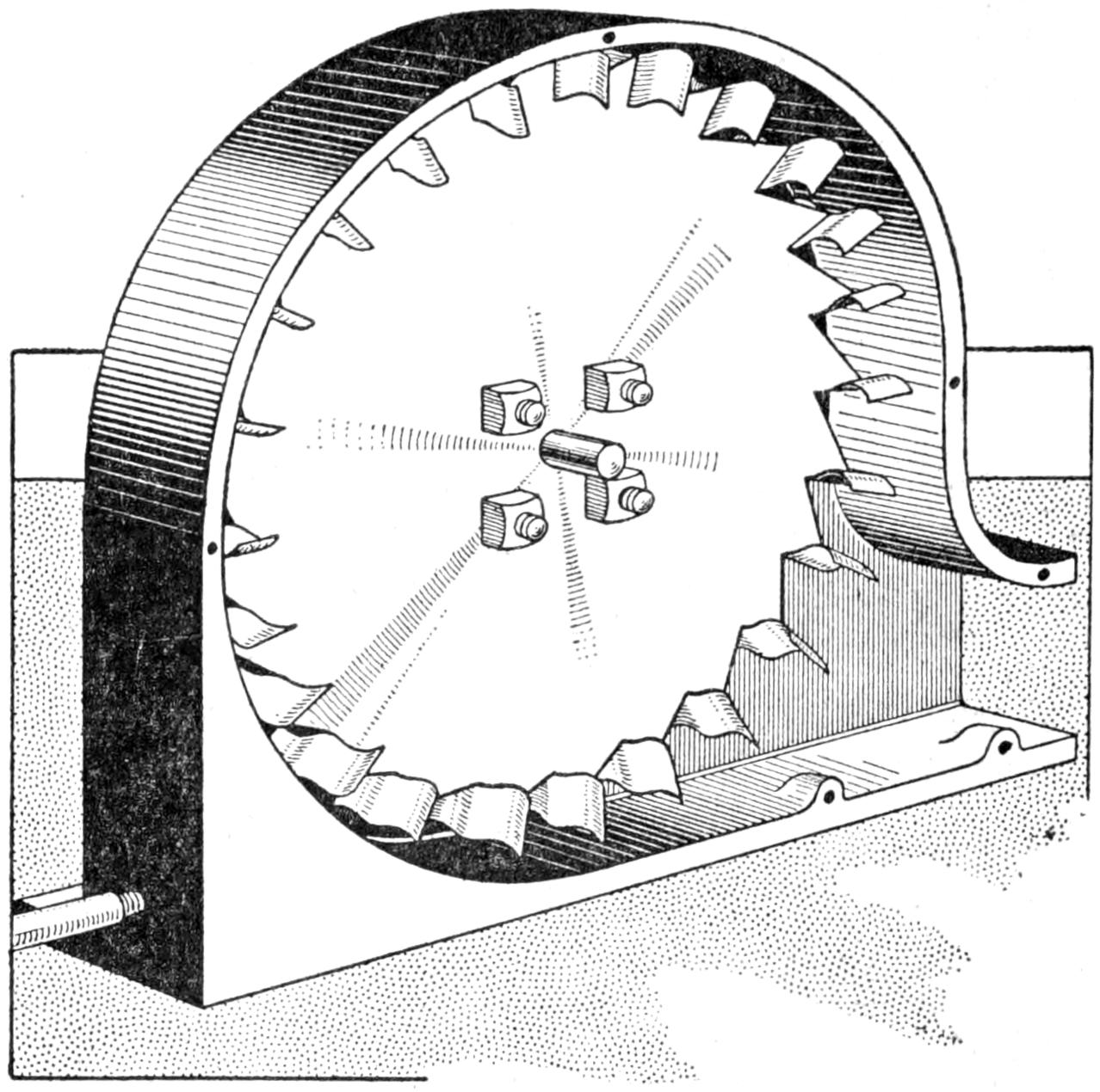
View of the Water Turbine with the Cover Plate Removed, Showing Inlet and Drain
Wooden patterns are made for the housing, the main casting and the cover plate being cast separately. The pattern for the cover plate should provide for the bearing lug, as shown in the sectional detail, and for the angle forming a support at the bottom. Special attention should be given to allowance for proper draft in making the pattern for the main casting; that is, the edges of the reinforcing ribs, and the sides of the shell should be tapered slightly to make removal from the sand convenient. The advice of a patternmaker will be helpful to one inexperienced in this work, although many machine metalworkers are familiar with the process.
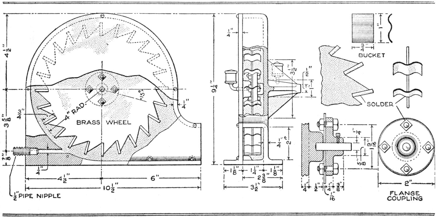
Details of a Water Turbine That will Give Considerable Power and Speed for Driving a Generator or Small Machine
The finishing and machining of the parts and their assembling should be undertaken as follows: Clean the castings and file off rough parts. Smooth the cover plate and the shell to a close[428] fit, and drill and tap the fastening holes for 8-32 machine screws. Drill ¹⁄₄-in. holes for the bearings, through the bearing arm and ¹⁄₄ in. into the lug on the cover plate. Drill and tap the two grease-cup holes for ¹⁄₈-in. pipe thread, Drill the nozzle hole ¹⁄₄ in., and drill and tap it for a ¹⁄₂-in. pipe nipple.
Lay out the wheel of ¹⁄₁₆-in. brass, making 24 notches in its edge. Fasten the wheel to the ¹⁄₄-in. shaft with a flanged coupling, fixing it with a setscrew. Bolt the flange to the wheel with 8-32 steel bolts. Make the buckets of ¹⁄₃₂-in. sheet brass, curved as detailed, and round off the edges. Solder them into place, using plenty of solder and making certain that the curve is set properly. Place drops of solder on the flange nuts to secure them. Place the ends of the shaft on two knife-edges, and balance the wheel by adding drops of solder to the lighter side. This is very important, as undue vibration from lack of balance will wear the bearings quickly.
Assemble the machine, using shellac between the cover plate and shell. Make connection to the water supply with a ¹⁄₂-in. pipe. Bolt the machine down, and do not let it run at full speed without load.
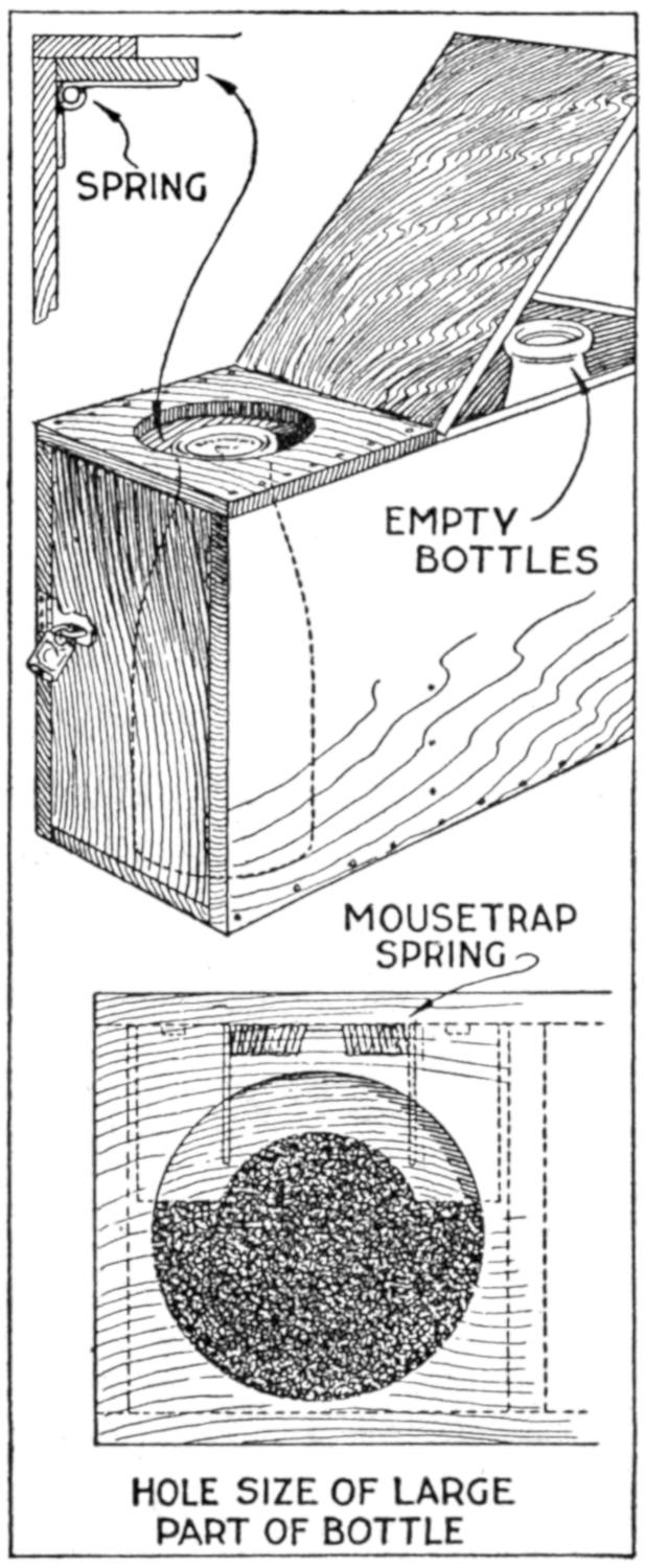
A mousetrap spring, provided with a suitable catch, was fitted into a box for milk bottles, and served to protect the milk bottle against theft by prowlers. The box was made large enough to hold several bottles, the empty ones in one portion and the filled bottles in another. The bottle is dropped through an opening in the locked end of the box and the spring forces up the catch. While this device may be tampered with, it guards effectively against the theft of bottles of milk, since most of those stolen are taken because they are easily accessible.—L. F. Head, Seattle, Wash.
¶The oxyacetylene flame may be used in cutting or welding steel cables, but such welds will not sustain the original safe load of the cable.
A discarded toothbrush, properly cleaned so as not to be insanitary, may be used in one or possibly more of the following ways: to raise the nap of white buckskin shoes, after polishing them; in reaching corners with shoe polish, or in cleaning out eyelets and corners; cleaning typewriter keys with benzine; polishing small parts of metalwork.—Joseph A. Cunningham, Philadelphia, Pa.

Having made a hunting knife and desiring a suitable sheath for it, I devised that shown in the sketch, which has the special feature that the guard on the knife handle locks in slots cut through the sheath. Two pieces of leather were used, one for the back section and the other for the shorter front piece. The sewing at the edges of the two sections extends from the level of the slots around the lower end of the sheath. Two slots were cut vertically through the upper portion of the sheath, which is fastened to the belt of the wearer, as indicated.—George H. Flint, Harrison, Me.
[429]
Old leaf springs obtained from a buggy were used to give the necessary spring to a diving board. One of the springs was set at each side of the board about 2¹⁄₂ ft. from the fixed end, and they were joined by a cross support of 2 by 4-in. wood, on which the spring board rested. Straps to check the strain on the springs from the rebound were provided.
When a camp fire is placed near a stream, water power may be utilized to turn the spit in roasting meat over the fire. The rod, on which the roast is suspended, should be extended, and supported at one end, over the water. A small paddle wheel may then be rigged up easily on the rod.
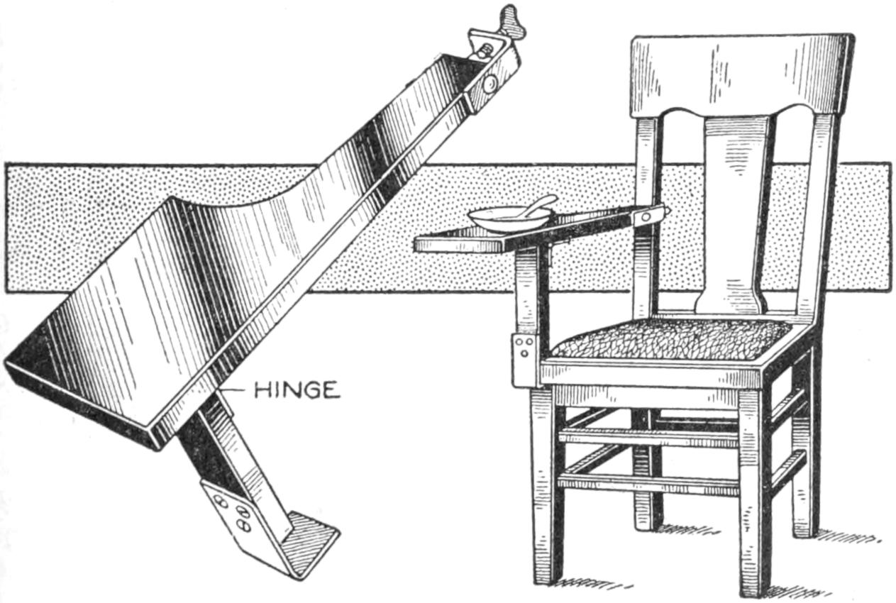
This Folding and Detachable Chair Arm Is Useful in the Home
The children in the home as well as others can make good use of a chair arm which may be attached quickly to an ordinary chair. The wide arm is clamped to the back of the chair by means of a strip of metal fitted with a thumbscrew, and the upright is fixed to the arm by a hinge, making it convenient to store the device. The lower end of the upright is fitted with a metal angle which fits on the corner of the chair.—J. F. Long, Springfield, Mo.
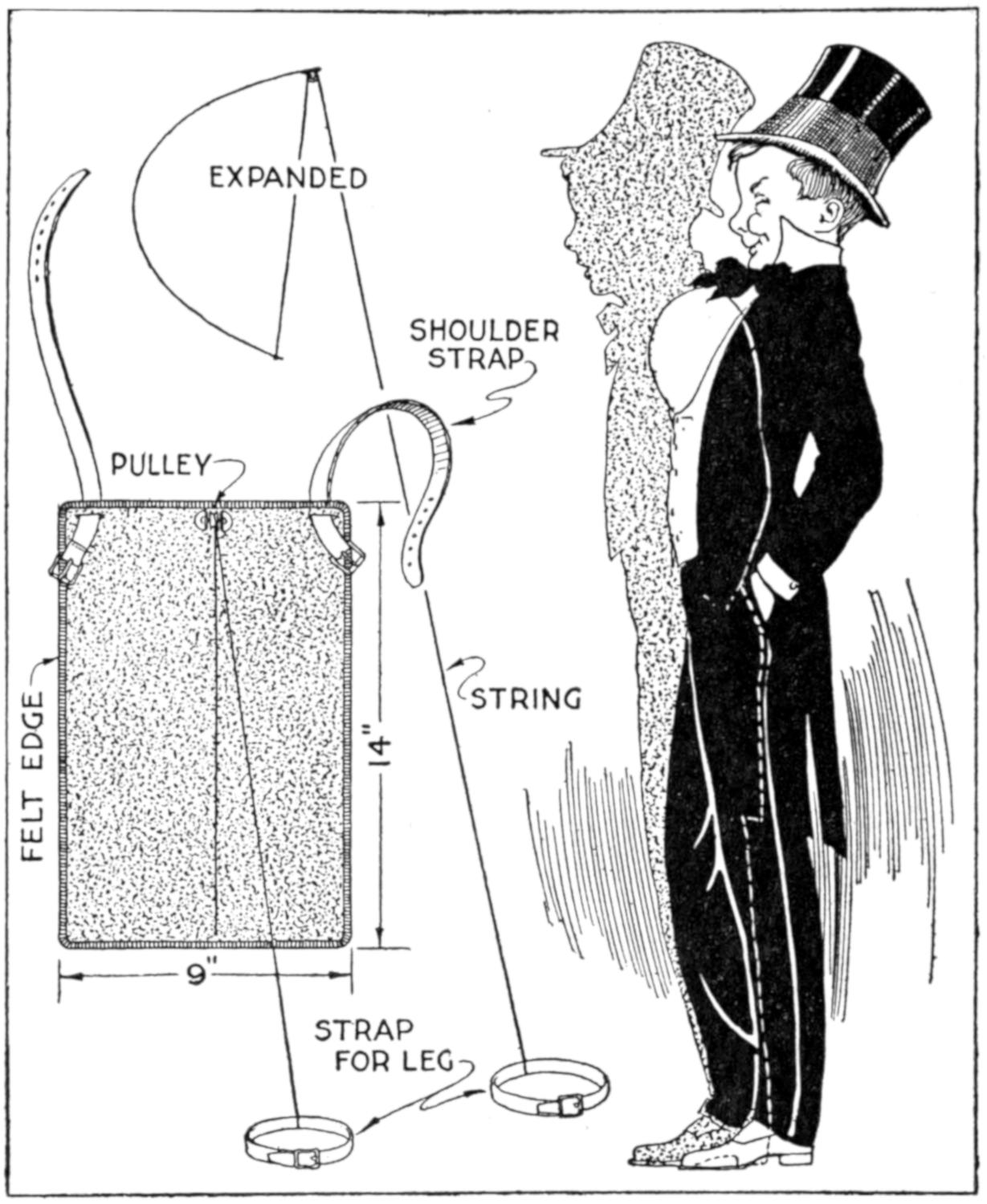
The Performer’s Chest “Swells with Pride” When He Draws on the String by Shifting His Position
A device used in an amateur vaudeville sketch with good effect, and which is interesting for play purposes, was made of a ¹⁄₃₂ by 9 by 14-in. piece of sheet spring brass, rigged as shown. In the center, near the upper edge, a small pulley was soldered, and at the center of the bottom edge a small hole was drilled. In it was fastened one end of a 4-ft. string which ran up through the pulley. The other end was fastened to a strap to fit around the leg just above the knee. At the two upper corners of the brass sheet two slots were cut to accommodate similar straps, as fastenings. When the wearer stands in a normal position the chest is as usual, but by straightening the body and slightly moving the strapped leg back, the brass sheet is bowed outward, giving the appearance indicated.—Arthur L. Kaser, South Bend, Ind.
¶Square cardboard disks fastened to the ends of a spool with thumb tacks will prevent it from rolling.
[430]
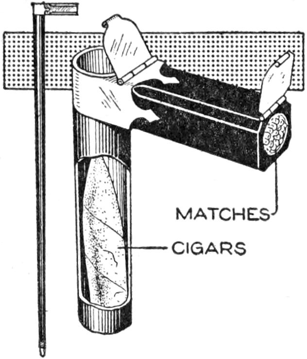
As a novelty in canes, a steel tube was provided with a suitable handle and used as a container for cigars and matches. The tube was fitted with a metal cap at its junction with the handle and the cigars are inserted or removed at this point. The end of the handle was bored out and also provided with a cover, as a match safe. The tube was enameled and varnished to resemble wood.—James E. Noble, Toronto, Canada.
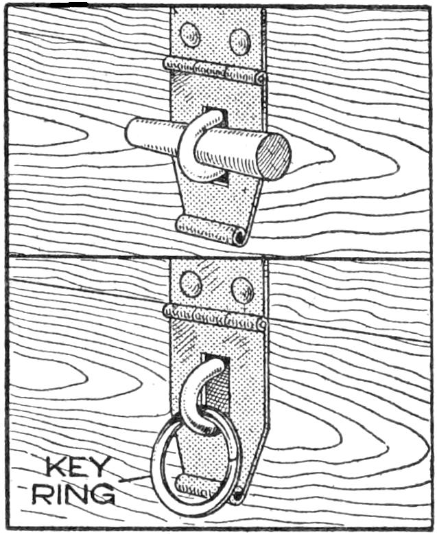
The usual box-cover fastener in the form of a staple and hasp can be fastened quite securely, and much better than with the use of a wood pin, by applying a key ring to the staple. This is to take the place temporarily in case the lock is lost or discarded.—James M. Kane, Doylestown, Pa.
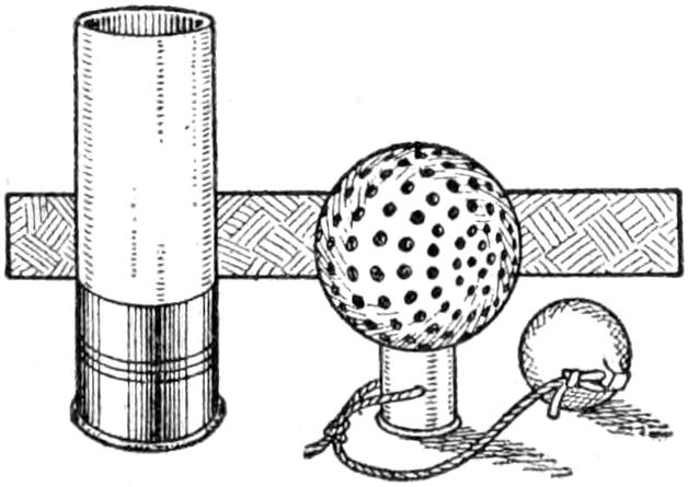
Instead of making golf tees in the usual manner I used the brass end of a shotgun shell, weighted with a small iron ball attached to a string. The device was made as an experiment and proved so useful and convenient to carry that I continued to use it.—Edward Beasley, Texarkana, Ark.
A patch of silk, properly applied makes a good repair for a hole worn through the canvas bottom of a canoe. Loosen the canvas for about 2 in. around the hole and apply thick shellac. Insert a piece of silk in the hole to lap under the edges of the canvas. Permit the shellac to dry slightly and smooth down the patch. Protect the joint further with white lead, smoothing over the patch and painting it when dry.
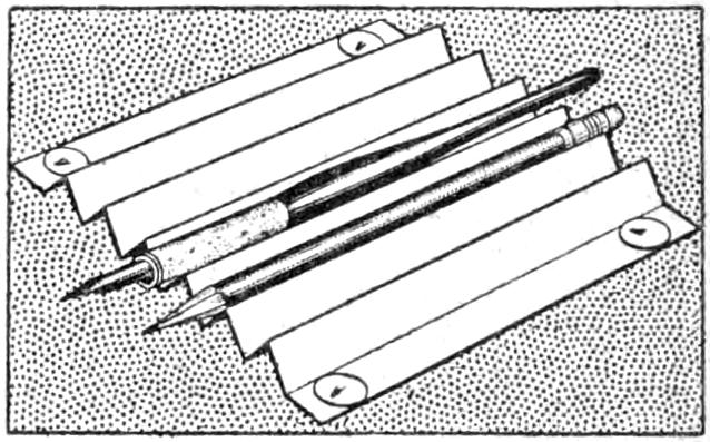
A piece of light cardboard, or sheet metal, may be folded into a neat and useful holder for pens, pencils, etc., on the desk or drafting table. In the latter case a piece of stiff drawing paper folded into V-grooves and tacked to the board, is convenient. For use on a finished surface the folded piece should be pasted on cardboard or otherwise fastened down.—William Robert, Springfield, Mass.
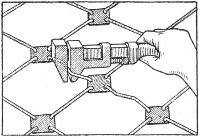
A couch spring of the type shown in the sketch sagged considerably, making it ineffective. The sag was taken up by bending the sections of wire with a monkey wrench, so that the entire spring was stiffened almost as satisfactorily as when new. Care must be taken that the wires are bent uniformly so that the strain is evenly distributed.
¶An eggshell may be balanced on the edge of a knife if the egg is “blown,” and then partly filled with sand.
[431]
The combination lock described has been used for years on lockers and letter boxes in a large public building. The details of a lock with three disks are given, and in Fig. 4 the use of two disks is suggested. The lock is made as follows: From a piece of ³⁄₁₆ or ¹⁄₄-in. hard wood, saw out three disks, A, Fig. 1, from 1 to 4 in. in diameter, according to the size of lock desired. For one with 2-in. disks, as shown, cut slots, B, ¹⁄₂ in. wide and deep, in the edge of the disks. For axles use ³⁄₈ by 2-in. hardwood dowels, C, with a six-penny headless wire nail in one end, leaving about ¹⁄₄ in. of it exposed.
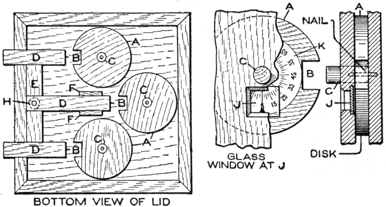
Fig. 1
Fig. 2
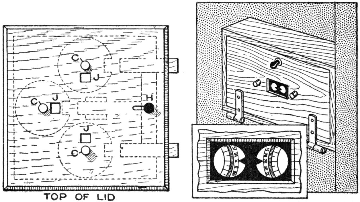
Fig. 3
Fig. 4
This Wooden Combination Lock Gives Good Service and is Easily Made
The case of the lock is shown in Fig. 1. It is made large enough to mount the disks, as shown. Around the edges of the inside surface of the lid fasten strips a trifle thicker than the disks. Place the disks in the positions shown, drilling small holes in the baseboard for the nail axles. The bolts, D, and the piece, E, are made of hard wood, fastened with a lap joint. On each side of the bar, D, fasten cleats, F, to hold it in position. The handle, H, moves in a slot in the lid, and is fixed to the bar, E.
The door, or lid, on which the lock is to be used, is provided with openings, J, as shown in Fig. 3. The axles C, project through openings, as bearings. When the windows J, through which the combinations are read, are made, place the ends of the bolts in the slots of the disks and screw the lock in position. Mark on each disk the point exactly in the center of the window, enabling one to work the combination temporarily. To lock the device, push the handle to the left and turn the axles. To unlock it, turn the axles until the pencil marks appear in the middle of the windows, and throw the bolts.
Next make paper dials, K, of a diameter as shown in Fig. 2. Divide the circumference into from 50 to 100 equal parts, according to the size of the dial, and draw radii, as shown. Number at least every fifth point. To the face of each disk, A, with small thumb tacks, fasten one of the dials, placing the combination numbers selected exactly over the pencil marks made in setting the temporary combination. Verify the combination before locking it. Unless the slots in the disks are a little wider than the ends of the bolts, the combination must be very closely adjusted. An aid in setting the combination is a line on the glass or a point of black paper, as shown in Fig. 2. The combination may be changed by setting the dials in new positions. The large number of combinations possible makes it very difficult to obtain the combination. For most purposes, two disks are sufficient in a lock of this kind.
¶A convenient method of supporting a garden-hose nozzle is to tie a loose knot in the end of the hose, arranging the nozzle to spray as desired.
[432]
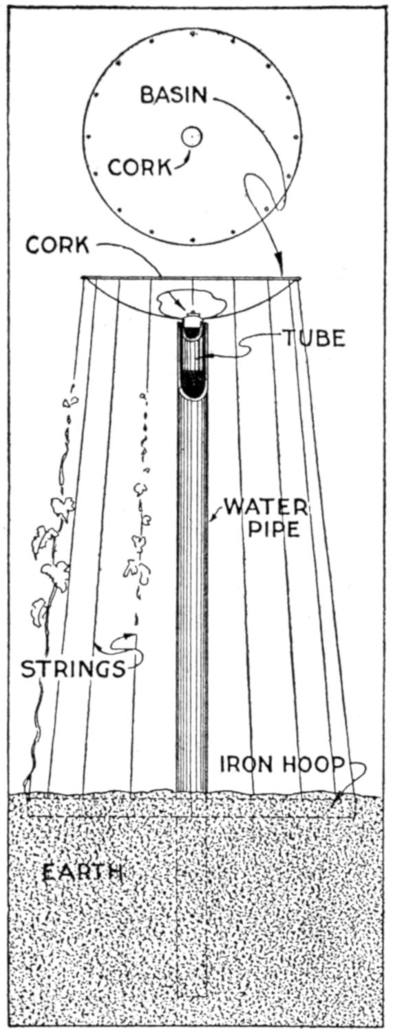
A bird basin can be made an attractive feature of a home garden, and that shown in the illustration was made easily of a metal basin and a section of iron pipe. The pipe was sunk in the ground to a depth of 30 in. and loose rock placed around the end of it. A shallow pan, hammered out of a flat piece of sheet metal and provided with a cork stopper, was fixed to the upper end of the pipe. Holes were made in the edge of the pan and strings to support morning-glories were attached from them to a hoop, set in the ground around the pipe. When it is desired to change the water in the pan it is drained off by releasing the cork.—Mrs. F. D. Reynolds, Stevens Point, Wis.
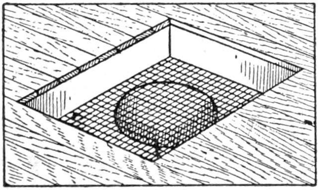
In order to recover small articles dropped through the floor-register grating of a hot-air heating system without the necessity of removing a section of the pipe, mesh gratings like that shown were fitted into place. Number six gauge wire mesh was used in pieces just large enough to fit into the metal box below the register. Access to the screen may be had by removing the grating—F. M. Ball, St. Louis. Mo.
Leather and metal-button clasps from suspenders are useful in repairing heavy gloves, large leather cases, and other articles on which the clasps have been lost or worn out. They may be sewed or riveted into place. Attached to straps, they are useful means of making a fastening, and may be applied to leggings, and other parts of outing clothes.
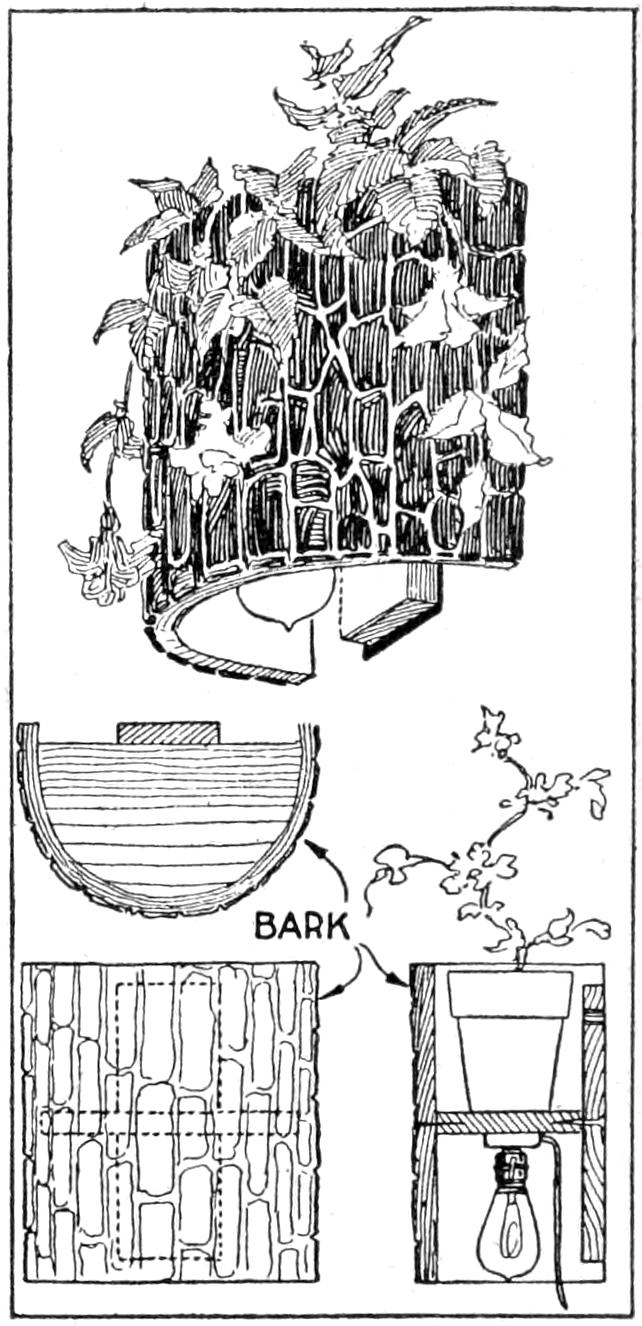
A combination flowerpot holder and reading lamp was made from two pieces of wood, bark, and a lamp socket, and proved to be a good shaded reading light. With a plant in the flowerpot, the fixture was made quite attractive by day. Maple bark, well dried out, was used. A piece of board, ³⁄₄ in. thick, was cut to fit the curve of the bark, and fastened to it. The former was then nailed to another board, ¹⁄₂ by 5 by 14 in., which formed the support for the fixture. A lamp socket was attached and a suitable current source provided.
A convenient attachment for the back of a chair is an extension padded to form a comfortable headrest. This may be made by fixing a padded piece of wood, 6 in. wide and 20 in. long, to the chair back by means of suitable wooden braces, notched to fit the top of the chair.
[433]
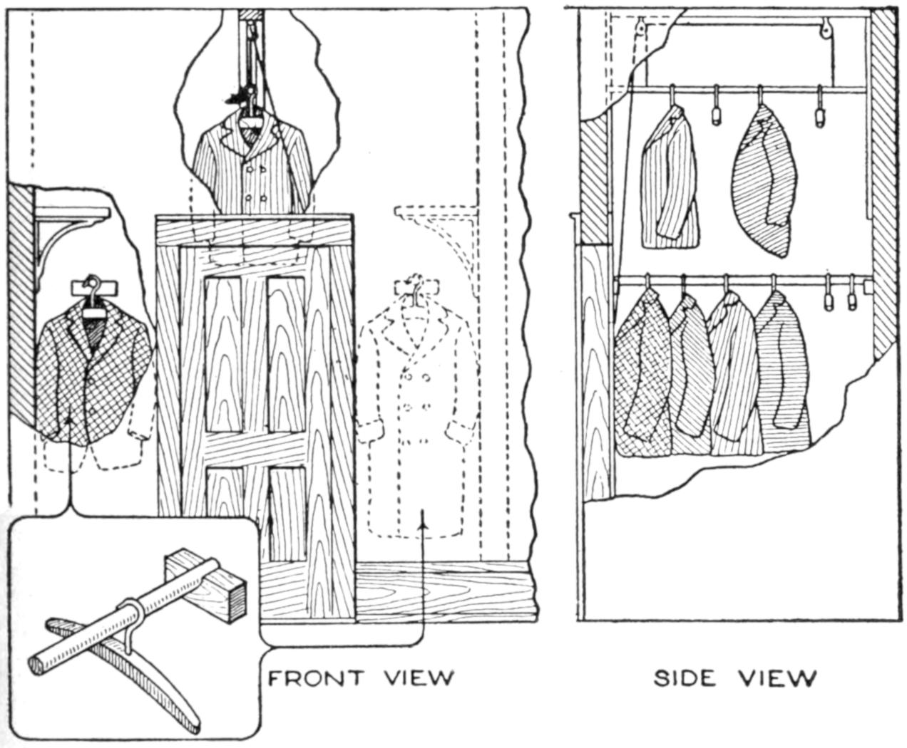
This Simple Rigging Gave Accommodation for a Large Quantity of Clothing in a Small Closet
It was necessary to store a considerable quantity of clothing in a small clothes closet, and the rigging detailed in the illustration was devised, and provided unusual accommodations. Wooden rods, 1¹⁄₂ in. in diameter, were set across the closet at each side of the door and supported on notched blocks, as shown in the detail at the left. The clothes used frequently were supported on these rods by means of hangers. For clothes out of season, or used only occasionally. a special rigging was arranged in the space above the door. A 1¹⁄₂-in. rod was fitted between the walls to slide in a groove at its ends. Strips nailed to the wall formed the groove. Cords, attached to the rod, as shown, and carried to the ceiling, where pulleys were fixed, made it convenient to raise or lower the rod. A sheet was spread over the clothes to protect them.—A. K. Hay, Ottawa, Canada.
A scoop that is serviceable for handling various kinds of lighter bulk material may be made by cutting the end from a cardboard box of suitable size and trimming it into shape. A handle may be provided by making a loop of cloth, or flexible cardboard, and fastening it with a paper fastener.
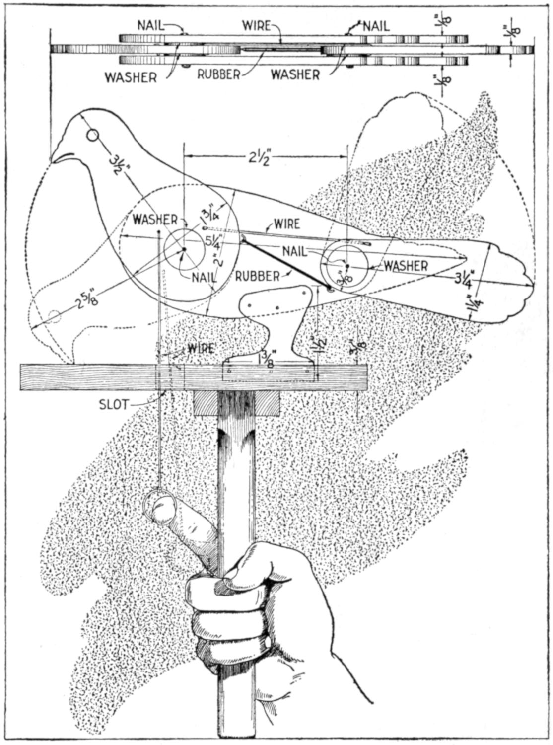
Draw on the Wire and the Head and Tail Bob Up and Down
When the head of the mechanical pigeon is lowered the tail rises, and the reverse. It is constructed as follows: Make paper patterns for the parts, which consist of two body pieces, a head, a tail, and the foot piece. The shape of the parts is shown in the sketch, the front body piece being removed to show the connections of the rubber and wire controlling the movements. The view above shows the fastening of the parts with nails. The main sizes of the parts, which are made of ¹⁄₈ to ¹⁄₄-in. soft wood, are: head, 1³⁄₄ by 3¹⁄₂ in.; body, 2 by 5¹⁄₄ in.; tail, 1¹⁄₄ by 3¹⁄₄ in.; foot piece, 1³⁄₈ by 1¹⁄₂ in. Mark the shapes on the wood, cut them out, and mount them, with a rubber band connecting the head and tail, as shown. Nail the foot piece between the body pieces, and pivot the head and tail on nails. Connect the head with a wire, having a loop on one end. Make the holder, and cut a slot into it for the draw wire, operated with the finger.—C. C. Wagner, Los Angeles, Calif.
[434]

The books, magazines, guns, fishing tackle, camera, etc., of the out-of-door man are often kept or laid aside in various places. To provide a good place for such equipment, I made the case shown. What apparently is a neat bookcase when closed, the top shelf used as a magazine rack, accommodates numerous other articles. After the “bookcase” has been examined superficially I open the door, swing the shelves out, and display back of them my guns, hunting togs and outfit. Two small drawers, covered by the upper rail of the door when closed, hold various small articles; and a blind drawer under the door holds shoes and the larger articles. I constructed this combination cabinet as follows: The lumber used was ⁷⁄₈-in. chestnut. The dimensions of the cabinet are 60 by 30 by 14 in. For the back of the bookshelf and cabinet I used matched ceiling. The door casings are 4 in. wide; the sidepieces of the door are 3 in. wide, the top, 4 in., and bottom piece, 6 in. wide. This cabinet cost me less than $3 and does the service of a gun cabinet valued at $30.—F. E. Brimmer, Dalton, N. Y.
In order to preserve photographic negatives and to make them easily available, the following homemade system was devised: The negatives are kept in envelopes having a print from the negative therein mounted on the face. A trial, or an inferior, print is used, and shows what negative it contains. Extra prints and enlargements are kept in the same envelope for each negative. On the face, or back, of the envelope is written data, such as name or title of subject, place and date taken, stop and shutter speed used, most suitable printing paper, developer, etc. This data may be kept in the negative envelope on a sheet of paper. This leaves the photograph album free from data that is of no interest to persons viewing the pictures. The envelopes are kept in their original boxes, classified as “Animals,” “Birds,” “Live Stock,” “Landscapes,” “My 1914 Vacation Trip,” and so forth.
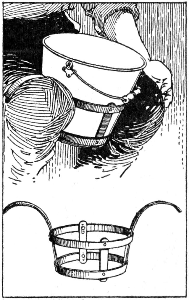
Becoming tired of holding the milk pail between my knees while milking, I made a contrivance of strap iron to overcome this. It is arranged so that the milk pail will just fit inside, the curved straps supporting the weight of the pail on the knees. The holder may be made of wood, with the possible exception of the curved arms, which should be made of pieces of iron, ¹⁄₈ in. thick and about 2 wide. The circular frame can be made adjustable to various pails by bolts set in holes in the bands.—J. C. Whitescarver, Miami, Okla.
[435]
Drawing tools, pencils, etc., were kept out of the way on a drawing board by inserting them in pockets drilled in the upper edge of the drawing board. A small brass plate, pivoted on the center, was used to cover each set of two pockets, and the latter were numbered on the upper surface of the board.—Elmer O. Tetzlaff, De Pere, Wis.
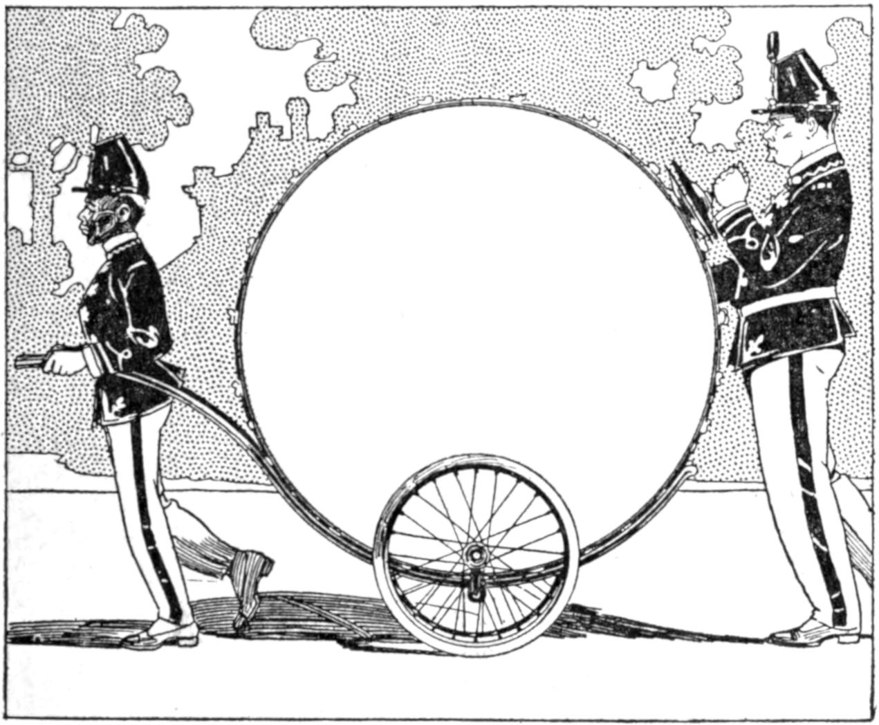
This Rubber-Tired Cart was Built Specially for a Large Drum Used in Parades
The inalienable right of the small boy to carry the drum in a parade was disregarded when the cart shown in the sketch was made for a large drum. Two rubber-tired wheels were mounted on an axle bent to fit the drum, and curved handles, forming a supporting frame, were fixed to it. The frame was made of hickory, steamed and bent into shape, and the drum was arranged to be quickly dismounted.—W. C. K., Mason City, Iowa.
An attractive and serviceable inverted-light fixture for a den and study was made at an outlay of about 30 cents, the details of construction being shown in the illustration. The light is distributed thoroughly, and with a 40-watt lamp is ideal for work at a desk. The lower portion A is a tin washbasin, costing 10 cents, and the part C is a cup-cake pan, costing 5 cents. The rim B is made of ⁵⁄₈-in. wood, 13 in. in diameter, and the disk E, 10 in. wide, is the round block cut from the center of the rim B. The uprights D are made of ³⁄₈-in. dowel rods and of a length suitable to the height of the room. They are glued and toenailed to the rim and disk. F is a cup-cake pan, and G is a drawer knob, fastened to the pan F. These parts can be omitted if desired. They are fastened to the top with wood screws.
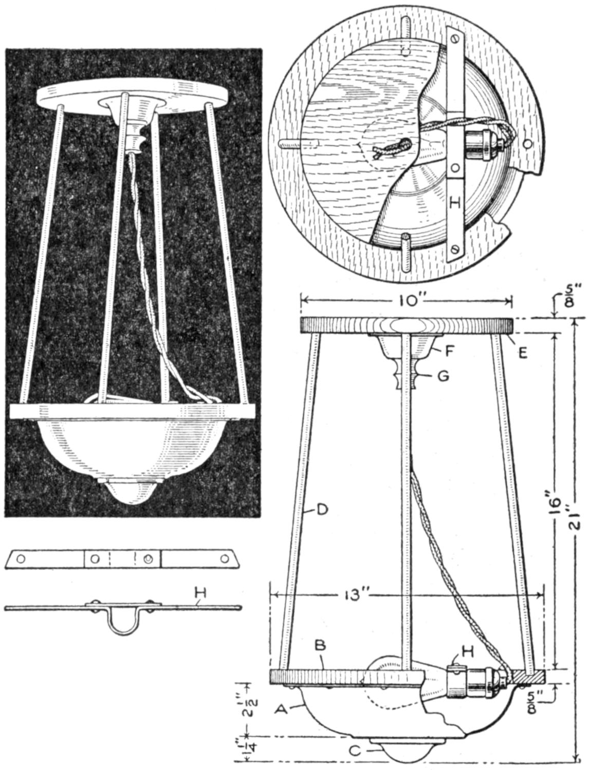
A Ten-Cent Washbasin was Used as a Reflector for This Light Fixture
The light socket is supported in a metal strap, H, having a rounded offset to match a bolted clamping strip. The inside of the basin, being tinned, acts as an excellent reflector. All parts except the inside of the pan are enameled white. The fixture is fastened to the ceiling with screws through the disk.—A. F. Krueger, Champaign, Ill.
¶The gummed portions of unsealed envelopes are often useful when a gummed strip is desired.
[436]
To make a sundial accurately it is necessary to lay out the lines for the particular locality where it is to be used, as a dial will vary slightly according to the latitude. The parts may be made of wood, metal, or stone. A good method is to have a bronze casting made from a wooden pattern. The lines may be cut with a lathe and planer in a machine shop, or engraved by hand.
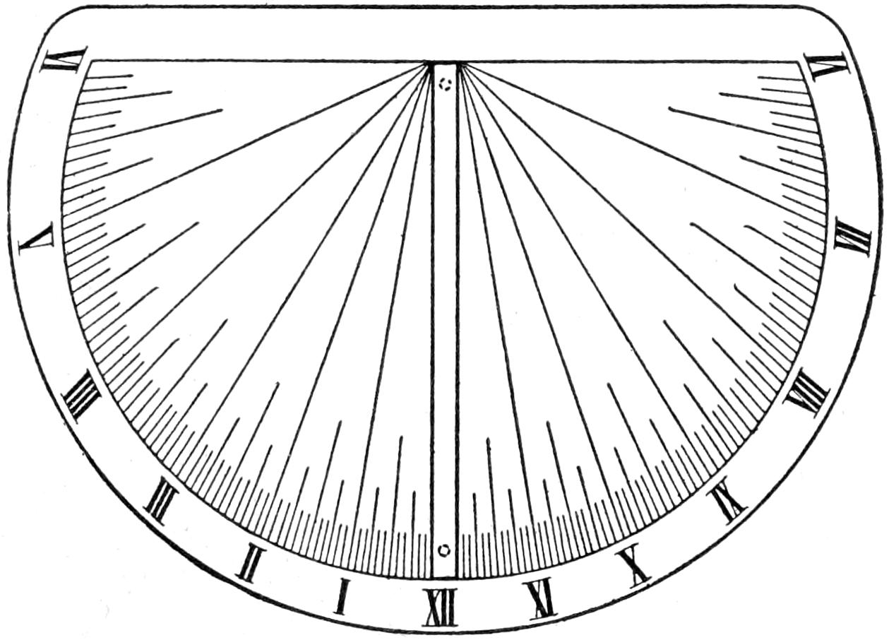
Fig. 1
Lay Out the Dial Plate Symmetrically, Allowing
Space for the Style
The illustrations show how the dial is made. The lines, as indicated in Fig. 1, should be laid out very carefully, first on a pattern. Draw a horizontal line near the top which represents the six-o’clock line, A-VI, in Fig. 2. Then lay out another line AH, at right angles to A-VI. Take a point C at any convenient place and construct the right-angled triangle ABD. The angle CAB should be equal to the degree of latitude of the place. The angle CBD equals CAB. Take a compass and set it to a radius equal to the side BD, and draw the quadrant DF from E. From D draw the line DG out for same distance and parallel with A-VI. Now divide the quadrant DF into six equal parts. Draw the lines E1, E2, E3, etc., and where they intersect the line DG, draw the lines from A, as A-I, A-II, A-III, etc. These are the hour lines. Divide each of the six divisions of the quadrant into four parts, and draw the lines, as shown between the 3 and 4 divisions. These are the 15-minute parts. Each of these parts may be divided in turn, and this is best done by eye, unless the dial is quite large.
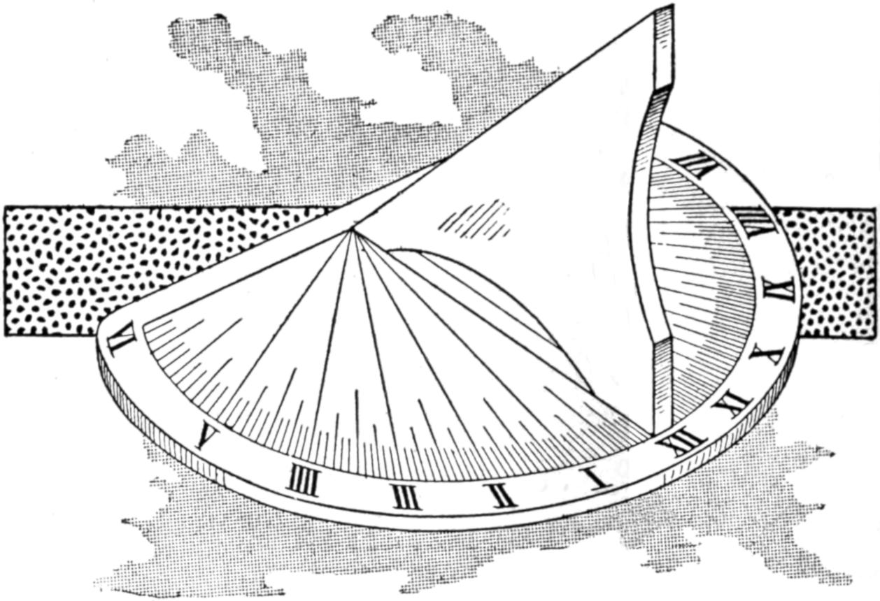
The Dial is Mounted Horizontally with the High End of the Style toward the North
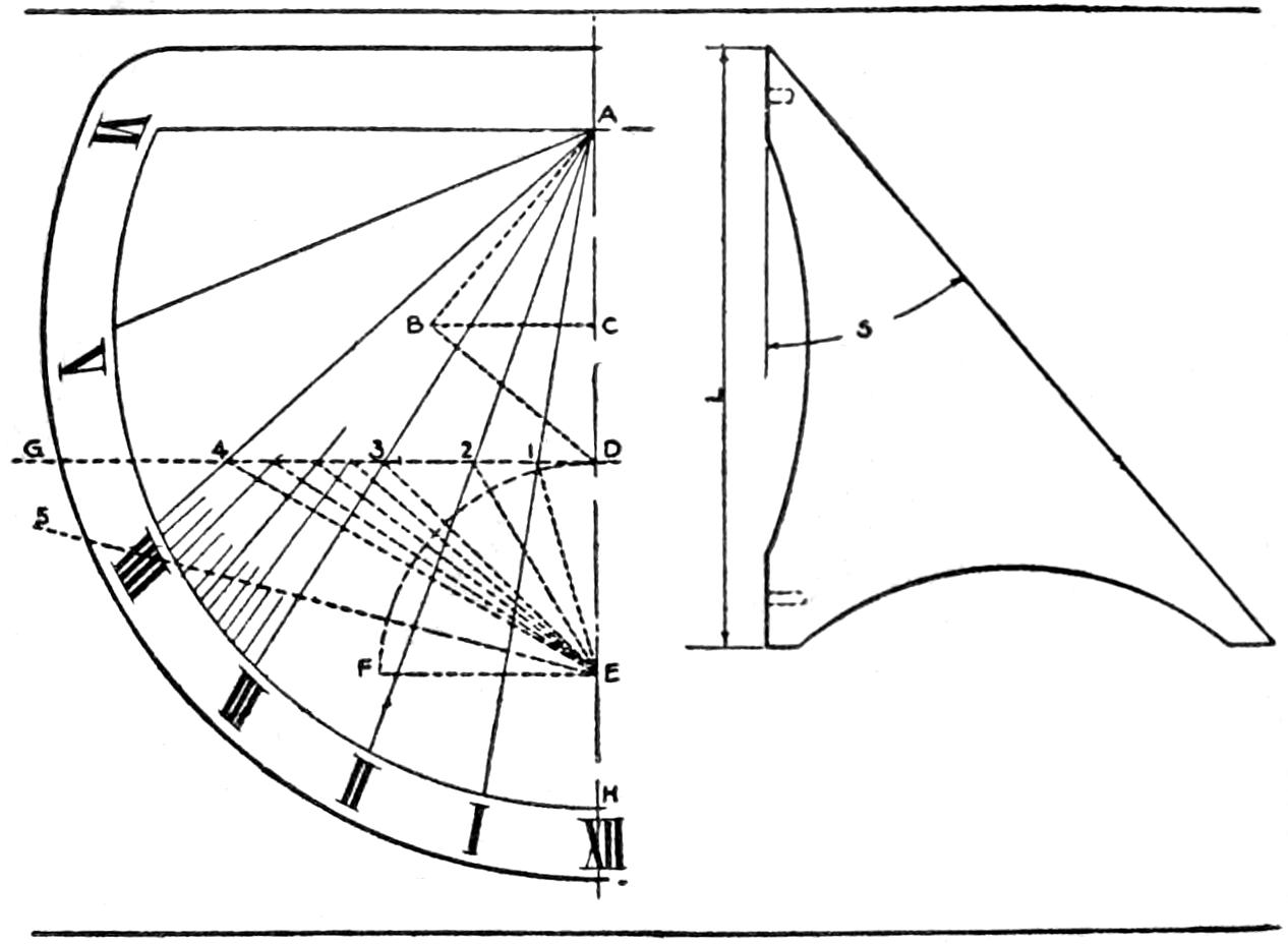
Fig. 2
Fig. 3
Diagram for Marking the Dial and Making the Style
This will complete one-half of the dial. The other half is done in the same manner, leaving a space between the line AH and its corresponding line for the other side of the dial. This space should be equal to the thickness of the upright shadow-casting piece, or style. The style has its base equal in length to the line AH, and its angle, S, equal to the latitude, or the angle CAB. It is mounted in the space with the high end at 12 o’clock. It may be fastened to the dial with screws passing through the base. Mount the dial horizontally on a suitable pedestal. The style should be exactly north and south, with 12 o’clock toward the north. The dial will be fast or slow over clock time. This is corrected by consulting an almanac and setting the clock accordingly from the dial. A correction plate may thus be made and mounted on the pedestal.—F. B. Walters, Baltimore, Md.
[437]
By mounting a 5-hp. motorcycle engine on a frame built of 2 by 4-in. stuff, and rigging the outfit on running gear made of gas-pipe axles, old buggy springs, and motorcycle wheels, I made the light roadster shown in the photograph, at small cost. It develops 30 miles an hour easily, carrying only the driver, and has carried five persons. The frame is suspended from the springs, with an underslung effect, on the front axle. The power is transmitted by a friction drive, consisting of a fiber contact pulley, obtained from an old commercial car, and a disk used as a cutter on a plow.
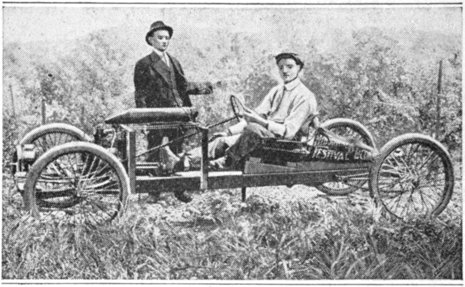
This Friction-Drive Cyclecar was Built in Spare Time by a Mechanic, Using Largely Makeshift Material
The front axle is of 1-in. gas pipe fitted with suitable-size solid nipples, and washers, at the bearings. The steering knuckle was made of steel shafting turned down to fit a pipe tee, set in the axle. The drive shaft is ⁷⁄₈ in. in diameter, and has a ball thrust bearing on the end. Sprocket gearing gives a ratio of 6 to 1, on high speed.—E. L. Munsen, La Conner, Wash.
Holes in aluminum ware may be mended by plugging them with rivets as follows: Make a rivet of lead or solder, and enlarge the hole to fit the rivet tightly. Insert the rivet from the inside and back it with a piece of hard wood, or metal. Rivet the other end to fill the hole and lap over it slightly. Suitable rivets may be made by cutting a lead wire, about ³⁄₄ in. long, and of the desired diameter, on which a head is formed by riveting down the end. The wire is set in a hole in a block during this operation.—L. C. Burke, Madison, Wis.
Trouble is sometimes experienced in feeding cards into a typewriter, and this may be overcome by providing a paper sheet as a leader. Run the sheet of paper into the machine and feed the card in after it, lapping their adjoining edges. This prevents the edge of the card from catching on the rolls.
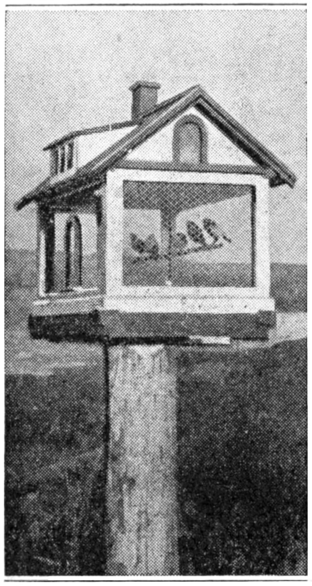
An outdoor birdhouse, which has proved popular in various sizes, especially for canaries, is that with a bungalow roof, and sides of wire netting, as shown in the photograph reproduced. While a number of these houses were made in a workshop to order, the construction is so simple that boys will find considerable fun in making them, especially in framing the roof. The house shown is 18 by 28 in., and 14¹⁄₂ in. high to the eaves strip. The body of the house is made in two side and two end frames, fastened at the corners with screws. The wire is put on the frames before[438] assembling them. A small, sliding door, of wood and wire, is provided, or one end may be made in two frames, one of which is hinged for a door. The eaves should extend at least 2¹⁄₂ inches.—H. L. Coolidge, Pasadena, Cal.
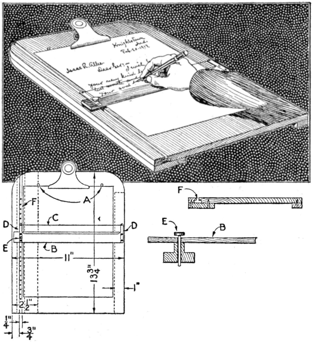
The Height of the Letters is Gauged by a Guide Wire
To assist my father in writing, notwithstanding his blindness, I made the machine shown in the illustration. It has been in use two years, and proved thoroughly practical. It consists of a board, ¹⁄₂ by 11 by 13³⁄₄ in., on which the paper is held by a clip. Two stops, A, insure a good alinement of the sheet. A T-square, B, slides in a groove at the left side; the upper edge is beveled. At a distance of ³⁄₄ in. from this edge is stretched a brass guide wire, C, by means of which the height of the script is gauged. The wire is supported on brass strips, D. When the line is written, a pin, E, set in one of a row of holes in the groove F, is raised, the T-square moved, and the pin inserted in the next hole below, giving the correct spacing. As the wire does not touch the paper, either ink or pencil can be used. The board consists of four pieces, glued, and fastened with screws, as detailed.—Arthur E. Tremaine, Brookline, Mass.
It is often difficult to obtain cardboard tubes as foundations for coils of special sizes, and the following is a practical method for making them as desired: Cut a strip of cardboard somewhat wider than the length of the tube desired and about 2 ft. long. Soak the cardboard in water until it is quite pliable. Wrap it tightly around a wooden rod of suitable size, gluing or shellacking each successive layer. When the desired thickness has been obtained, bind the tube with string, and place the whole in a moderately warm oven to dry. The tube may then be cut to length.—Alexander V. Bollerer, New Britain, Conn.
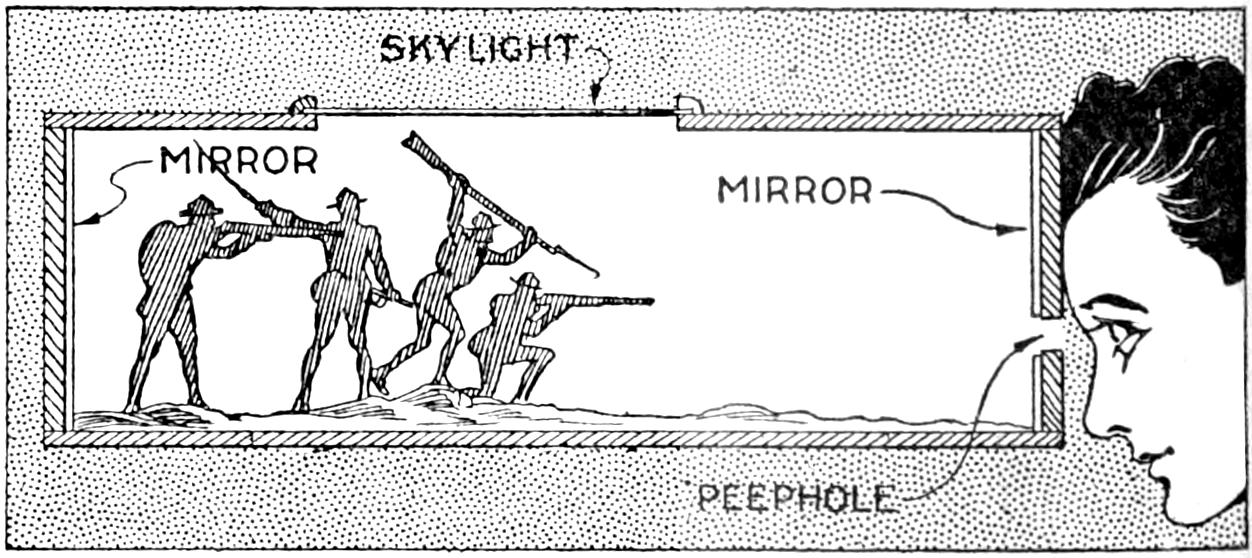
By Reason of the Mirrors, a Few Soldiers Appear as an Army
A play device that will afford much amusement and which is interesting for boys to make is that shown in the sketch. To make the peephole cabinet, obtain a box of suitable size; fasten a piece of looking-glass inside, at each end. Make a peephole at one end of the box, and rub the silvering from the back of the looking-glass at the hole. Place a few metal soldiers, horses, etc., along the sides of the box 1 or 2 in. apart, one being set to hide the reflection of the hole. By looking through the hole an endless army may be seen. Light is provided through the skylight at the top, which is fitted with ground glass or tissue paper. This device perplexes most persons who are not familiar with its construction.—James E. Noble, Portsmouth, Canada.
[439]
In photographic work, and in the shop or laboratory, chemicals carried in shallow trays are easily spilled. In photographic work, especially, this endangers materials used, as the spilled liquid dries and dust affected by it may spoil chemicals with which it comes into contact. The tray should be carried in a larger pan or basin partly filled with water, thus keeping the tray level.
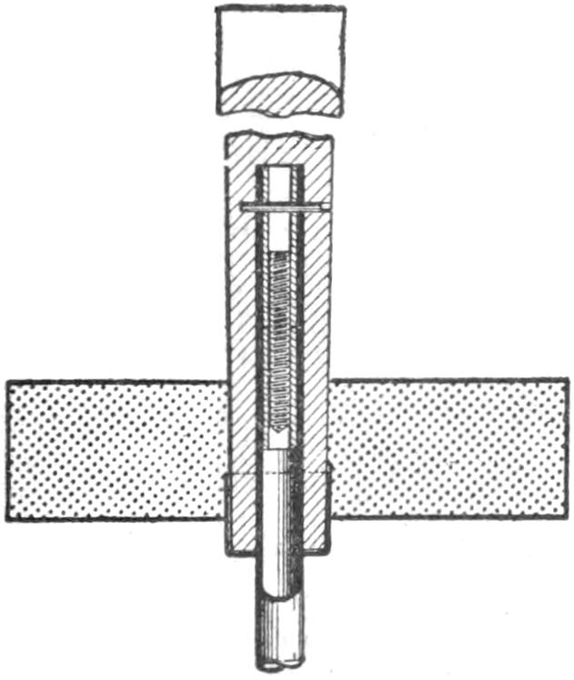
A parasol or umbrella with a detachable handle is a great convenience in packing when traveling, and a handle may be made detachable as follows: Remove the handle by using a block of wood and a hammer. Clean out the hole, and polish the steel stem with emery, as far as it goes into the handle. Cut off 1 in. from the end, and then solder a section of brass tubing into this piece, and another section into the end of the stem. The abutting ends are then tapped to fit an 8-32 screw, which is then soldered into the shorter piece, as shown. The latter is pushed into the handle, and a hole, ¹⁄₁₆ in. in diameter, is drilled almost through the handle. A piece of wire nail is driven into this hole. By making the screw fast in the handle rather than in the stem, the threads are protected, and the length when taken apart is correspondingly reduced.—John D. Adams, Phoenix, Ariz.
¶To renew a typewriter ribbon, roll it on a spool and apply a very small drop of glycerin at intervals of several inches, with a fountain-pen filler, and permit the glycerin to soak in thoroughly.
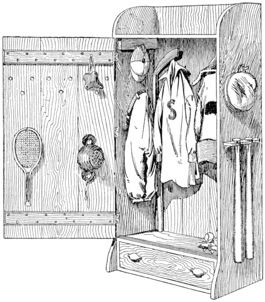
The Boy Who Takes Pride in His Athletic Equipment will Find Much Pleasure in Making This Cupboard for It
The boy should have a place in the home for his sports togs and equipment, and a cupboard like that shown can be made easily for the purpose. Its size will depend on the quantity of articles to be stored. A good size is 12 by 30 in., by 5 ft. high. Plain boards are used, and for the door they are fastened together with cleats and screws. The drawer is convenient but not essential.—J. D. Hough, Toledo, Ohio.
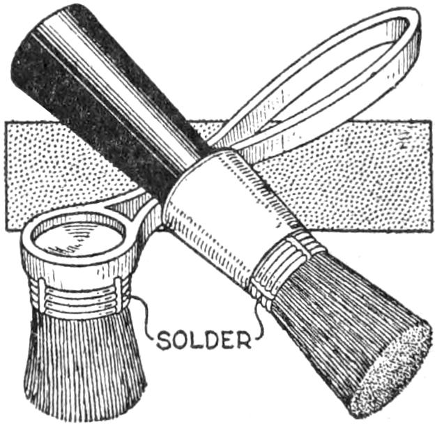
The bristles of brushes used for applying shoe polish and for painting through stencils often curl so much that the brush becomes almost useless. In order to overcome this I bound the bristles with several turns of wire and soldered them into place as shown. When desirable, part of the wire may be removed by cutting it at the solder.—Hugo Kretschmar, West Nyack, N. Y.
[440]
Good use was made of an old table, one leg of which was broken, by removing two of the legs at one side and fitting the table against a wall. A wide board was set on the back edge of the table, against the wall, and provided a rack for tools. A drawer was fitted into the front of the table, and a small iron vise was clamped at one end. The arrangement provided a convenient bench for home shop work.
Instead of scratching titles on photographic negatives, which often produces a poor result, a good method is to write the title on the sensitive paper with black ink before printing. Care must be taken not to scratch the paper. The toning and fixing baths wash away the ink, leaving the script or lettering white. The negative is thus unmarred.
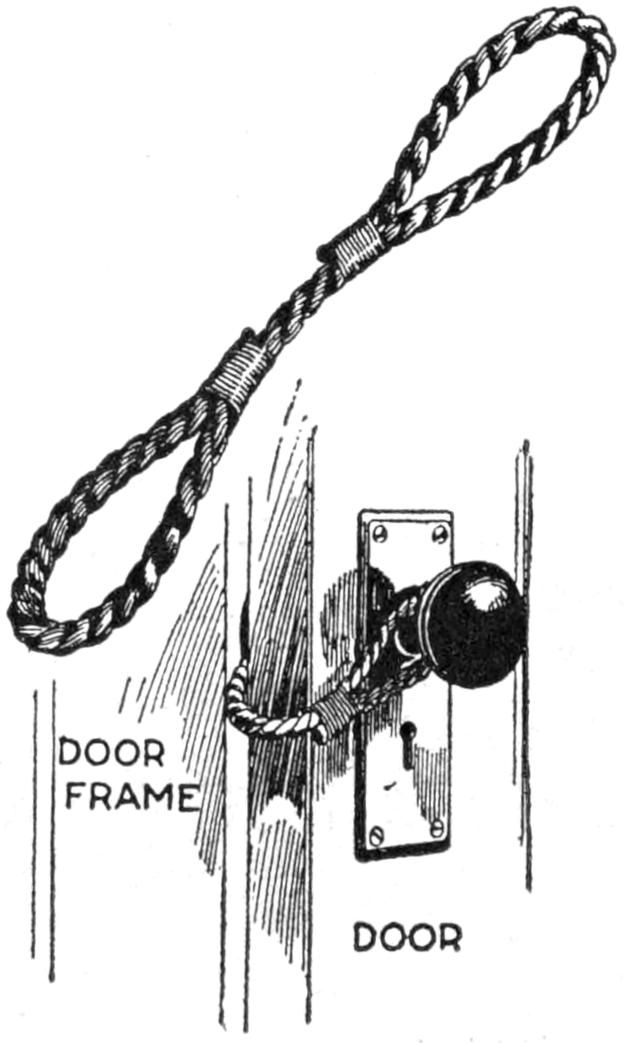
An antislam pad, made of a piece of rope and fixed to the knobs of doors, is in general use in a large hospital. The device is made by forming loops on the end of a short section of rope, as shown, and fitting them over the door knob. This also prevents the closing of the door so that a patient may be heard in calling an attendant.—C. M. Hall, St. Louis, Missouri.
¶Curtain rollers should be arranged so that the direction of pull on the tacked edge of the curtain is away from the end.
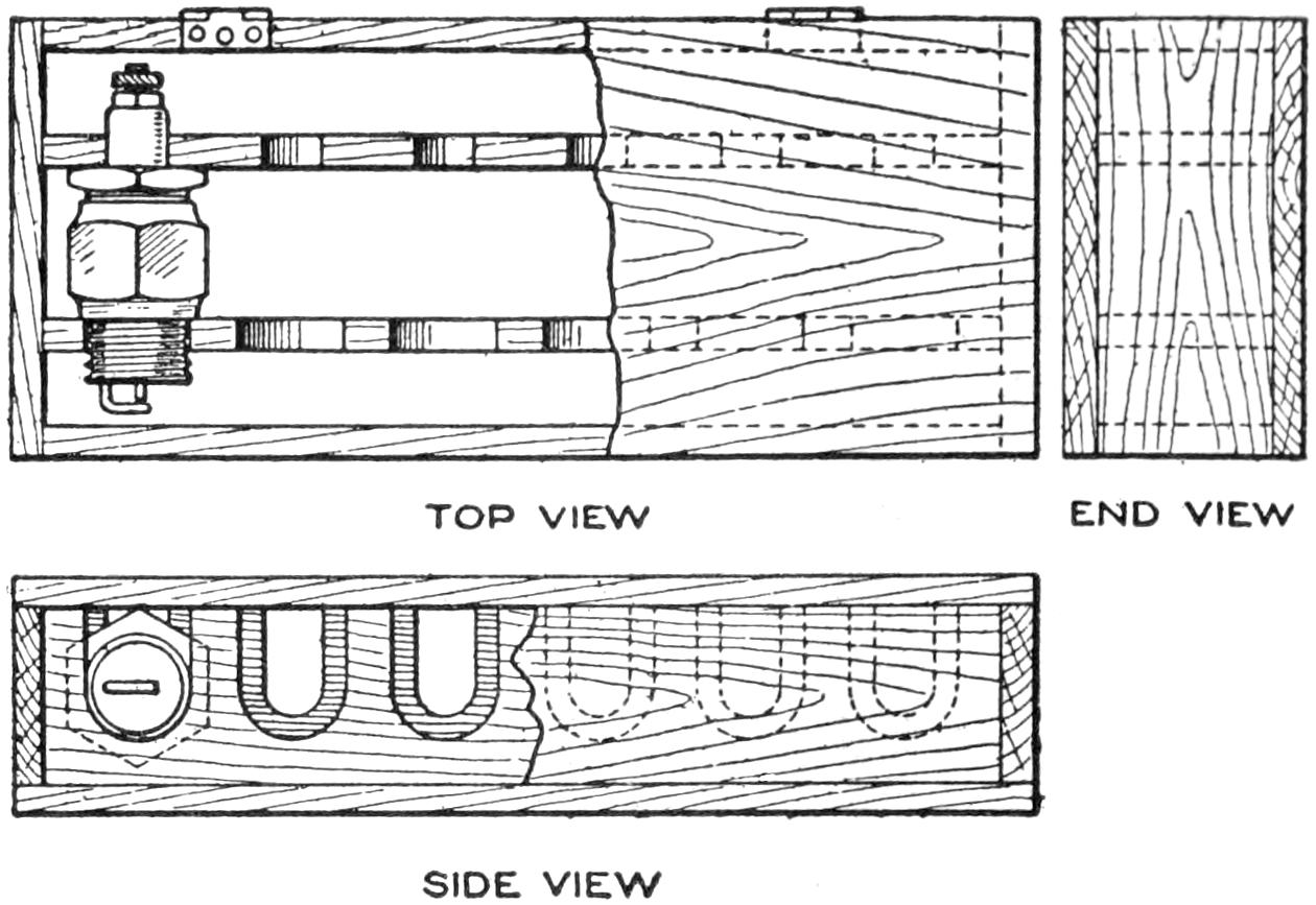
The Spark Plugs are Fitted Compactly in the Case and are Protected from Damage
Damage often results to spark plugs which are thrown in the tool box of an automobile, and the use of a small case for the extra spark plugs is desirable. Partitions may be fitted into an old box of suitable size, or a case may be specially made. That shown was designed to provide for six spark plugs in a minimum of space. It was made of ¹⁄₄-in. wood, and of a length so that the spark plugs could be slipped in the recesses only by turning the faces of adjoining plugs together. A hinged cover keeps them firmly in place.—E. R. Mason, Danville, Ill.
Two ⁷⁄₈-in. boards, 12 in. wide, between which two 12-in. pieces of 2 by 4-in. wood are bolted, provide a strong spring seat for a wagon. The boards are cut to a suitable length, and the 2 by 4-in. pieces are set near the middle, and about 8 in. apart. This gives a spring seat at each end of the device.
A strong barrel may be made into a comfortable chair by cutting it halfway through at the middle and shaping the remaining upper portion into an arm and back rest. Holes are bored at the seat level and at the back, and wires woven through them to form a backing for excelsior-stuffed cushions.
[441]
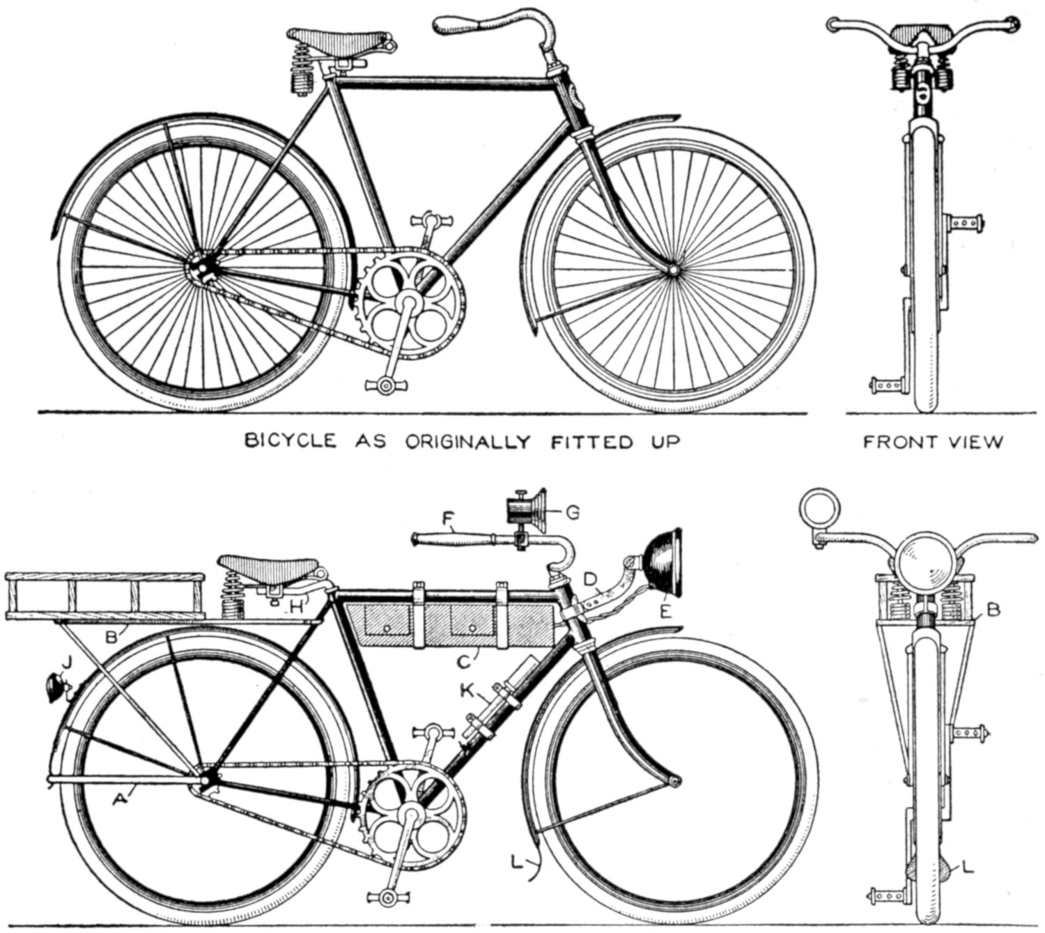
Comparison of the “Before and After” Illustrations Shows Strikingly the Resemblance to a Motorcycle
The boy who cannot own a motorcycle but who has a bicycle, may remodel it to resemble a power-driven machine by fitting it up with equipment, much of which can be made in the home workshop. The illustration shows how an ordinary bicycle was improved by several practical fittings. The lower end of the mudguard of the rear wheel was extended to form a clip, for the homemade stand A. Brackets were made of strap iron to support the bundle carrier B, the basket of which was made of wood. The tank C, 3 by 3 by 21 in., with two compartments and doors, contains batteries and tools. It is fastened to the frame by means of two bolted straps. The bracket D was made of strap iron, to support the electric headlight E. The handlebars were extended, as shown at F, and the horn G was provided. The seat post was lengthened by welding a piece to it, and reversed, as at H. A tail light, J, and a pump, K, held by straps, were provided, and the front mudguard was fitted with a leather piece, L, shaped as shown in the front view.—P. P. Avery, Garfield, N. J.
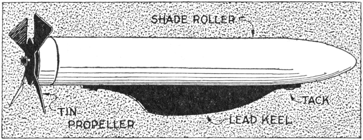
This Submarine’s “Engine” is Wound by Means of the Propeller
The submarine shown really goes, and was made of a bit of tin, some lead, a few brads, and an old window-shade roller, with a good spring. The spring is the submarine engine. Saw off the roller 3 in. beyond the inner end of the spring, and shape it like the bow of a submarine. Flatten a piece of lead, and fasten it to the bottom of the boat for a keel. Experiment until the keel is of the right weight, and in the proper place, permitting the boat to move evenly, just below the surface of the water. For the propeller, cut a 2-in. tin disk as shown, and bend the blades into shape. In the center make a hole to admit the end of the spring, to which it is then soldered. Wind up the “engine” by turning the propeller. The shade-roller spring can also be used for other toy craft.—E. P. Sullivan, Arlington, Massachusetts.
¶Rub powdered graphite on rubber and asbestos gaskets so that they may be removed easily when desired.
[442]
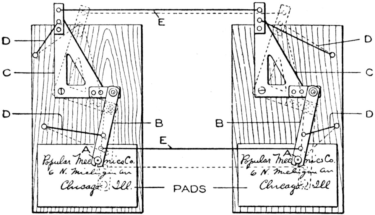
A Message Written on the Pad with a Pencil is Transmitted to the Other Pad at a Considerable Distance Away
An interesting and novel construction for amateur or boy mechanics is a telautograph or writing telegraph machine. The instruments, as shown, are duplicates with the exception of the placing of the rubber bands. They can be made in different sizes, and satisfactory results were obtained by making the base 7 by 12 in., the arm B 5 in. long and ³⁄₄ in. wide, and the triangle C 6 in. by 3¹⁄₂ in. A hole is bored in the arm B, slightly smaller than the pencil to be used and a slot sawed from the edge to hole, so that when the pencil is forced into the hole it will be tightly gripped, as at A. The arm B is fastened to triangle C, to move freely. The triangle is fastened to the base, and can also move freely. The rubber bands D are stretched tightly to hold the moving parts in position. The strings E should be strong, and stretched taut.
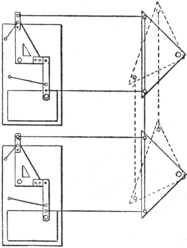
The larger diagram shows the instruments placed in parallel position. The smaller diagram shows how they can be placed one above the other. An unruled pad is fastened to the base of each instrument with thumb tacks. The operation may be traced by noting the successive action of the parts when the pencil on the pad at the left is moved in writing a message. The pivoted triangle communicates the action to the string E, which actuates the other triangle and its lever system. The rubber bands serve to steady the action. The instruments may be arranged a short distance apart for play or experimental purposes or set in rooms on different floors, by making suitable pulley connections for the cords E.—William Freebury, Buffalo, N. Y.
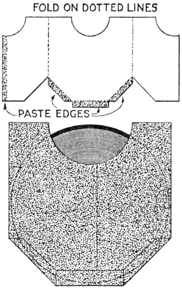
Having been bothered with the edges of square paper covers of disk records curling, making it unhandy to place them in a file, I remodeled them as shown in the sketch. The covers without the lower corners were so convenient that I made others by folding and pasting paper of the shape shown in the pattern. It was found desirable to use a good quality of paper for the new envelopes as this gave added protection.—J. H. Moore, Hamilton, Ontario, Can.
A deep funnel, or cone, made of sheet metal and attached to an ordinary platform weighing scale or a draw scale, is useful especially in weighing live poultry. The fowl is placed in the funnel head first and remains quiet while being weighed, which is not the case in most common methods of weighing. The funnel is mounted on three legs, for use on a platform scale, and suspended from a ring by chains, from the hook of a drawspring scale.—C. W. Reemtsen, Des Moines, Ia.
[443]
The surface of glass on which pictures are to be transferred must be thoroughly clean. A coat of nearly colorless varnish is applied, and permitted to dry overnight in a room free from dust. Wet the picture, soaking it in clear water for about 10 minutes. Place it on blotting paper with the front side down, leaving the back wet. Varnish the glass again, and place the picture face down on the varnished surface, pressing out the bubbles, working from the center out. Rub on the back of the transfer paper until the picture is transferred to the varnished surface, and remove the paper carefully. Permit the picture on the glass to dry, and then varnish it.
A milk driver who had many extra orders of milk and cream to deliver had considerable difficulty in keeping track of the orders. He overcame this difficulty by the use of a clip attached to the steering wheel of his truck. He got a spring clothespin, wired one side of it to one of the spokes of the steering wheel, and now places his extra orders in a ring attached to the clip, as they come on his route. When he makes a delivery, he moves the memo on the ring, bringing the next order before him. This method can be used in many other businesses, where articles such as newspapers are delivered on routes.—Francis W. Nunenmacher, Berkeley, California.
¶To counteract mildew on canvas, coat the parts with soap and rub well with powdered chalk or whiting.
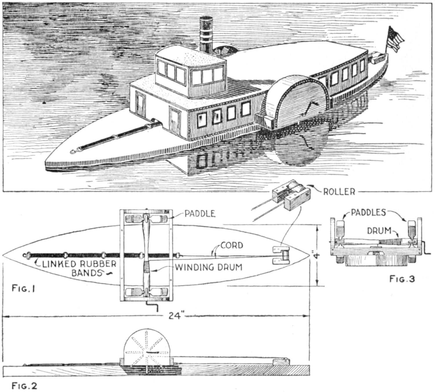
Fig. 1 Fig. 3
Fig. 2
The Rubber-Band Motor is Wound Up at the Crank, and Propels the Boat About 20 Feet
Only a few boys have ponds of their own, in a pasture, perhaps. But there are miniature lakes in our city parks, pools at our summer camps, and old water holes in the woods; if all of these fail, a boy can still sail his ships on the bathtub sea. A simple side-wheeler, built of wood, is shown in the sketch. It winds up with a crank and runs 15 to 20 ft. A float is made by pointing the ends of a thick board, the dimensions of which are given in Fig. 1. On this the paddle-wheel frame is nailed, as shown in the top view, Fig. 1, the side view, Fig. 2, and the end view, Fig. 3. It is made of thin wood. A broom-handle section, just long enough[444] to slip into this frame, is whittled to form a winding drum, and fitted with paddles, wire axles, and a crank. A second shorter section of the broom-handle, set between blocks nailed to the stern, serves as a roller for the rubber bands. These, linked together and tied to a length of heavy cord, as shown in Fig. 1, are fixed to the bow and run over the roller to the drum. The addition of a top, or lid, of cardboard, wood, or tin, and painted to resemble cabins and pilot house, and fitted with masts and a smokestack, completes the model. Fig. 5 shows a similarly built stern-wheeler with the stern-wheel shaft set on brackets.—E. R. Smith, Walla Walla, Wash.
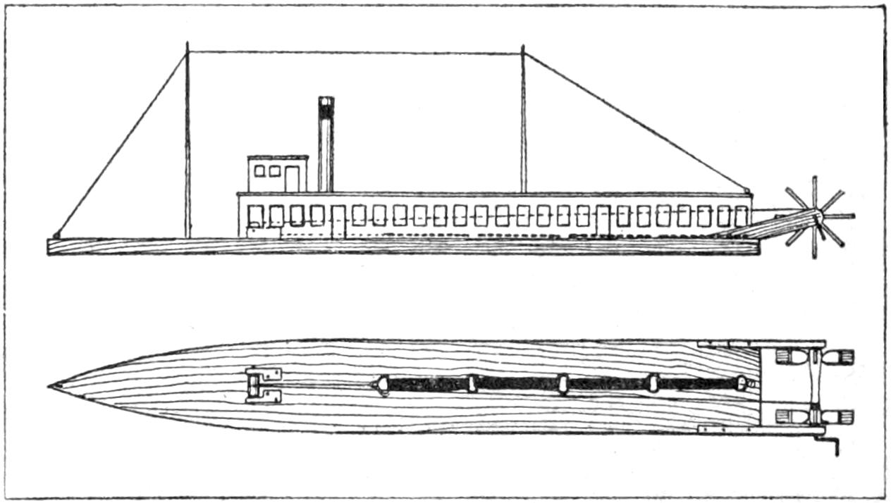
Fig. 5
The Stern-Wheeler Is Similar in Construction to the
Side-Wheeler as to Driving Mechanism
Buckwheat, oats, wheat, morning-glory seeds, and other grains and seeds, were successfully cleaned with a model thresher of simple design which I made from materials picked up in and around the farm workshop. It is 24 in. high, 14 in. wide, and 3¹⁄₂ ft. long. For a cylinder, I used a roller, 3 in. in diameter and 1 ft. long. The teeth are nails driven spirally about the cylinder in rows that alternate with similar teeth in the concave, the nails being driven ¹⁄₂ in. apart. The fan consists of a small roller upon which four pieces of tin are nailed. The beaters are larger rollers, into which wooden teeth are set. To hold the cylinder, fan, and beaters in place, four posts and two crosspieces were used, as shown.
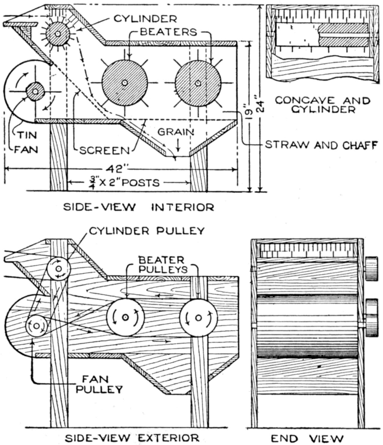
Made as a Model, This Small Thresher Proved Useful for Various Grains and Seeds
The power used is an 8-ft. windmill that I constructed, using a buggy wheel as the frame. The cylinder must be run at a fairly high speed, the fan nearly as fast, and the beaters may be run much slower; this is taken care of by the relative size of the pulleys. The screen between the fan and beaters must be of small mesh so that grain will not fall through into the fan chamber. The sieve through which the grain drops must be the proper size for grain, and can be varied for the different kinds of grain or seed threshed. It is better to put only the heads of grain into the thresher, as long straws twist about the rollers. The material to be threshed is fed into the cylinder in the usual manner, and takes its course as indicated by the arrows, the grain falling to the spout at the bottom, and the straw and chaff being blown out at the exhaust for it. Soft wood was used in the construction, ⁷⁄₈-in. stock for the heavier pieces, and ³⁄₈ or ¹⁄₄-in. stock for the other parts. The curved housing for the fan was made of tin. Leather or rope belts, fitted tightly, may be used. The power is applied on the cylinder pulley, hand or other power being suitable.—F. E. Brimmer, Dalton, N. Y.
A druggist recently puzzled thousands with a novel window display. A small white ball in a 1-in. glass tube, about 10 in. long, displayed in a show window, would sink to the bottom, then[445] slowly ascend, only to sink as before. A sign reading “What Makes It Move?” kept the crowd guessing. The tube was apparently filled with water. The construction is simple. The tube is about three-quarters full of carbonated soda water. The white ball is an ordinary moth ball. The ball sinks, and when it becomes soaked gradually as it lowers, bubbles of gas cling to it, carrying it to the top of the solution. There the gas escapes, destroying the ball’s buoyancy, and causing it to sink again, This process is repeated over and over.—David J. Lonergan, Minneapolis, Minnesota.
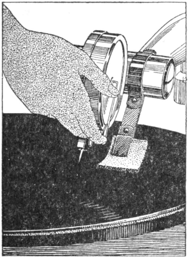
By providing a practical method of keeping talking-machine records free from dust automatically, as they are played, the life of the record is prolonged and the reproductions are more clear, and free from scratching sounds. A felt pad supported on a fixture made of a strip of brass does the work nicely. The pad is clamped in a clip at the end of the brass strip, and the entire device is held in place by the spring action of the upper clip, which fits over the end of the reproducing arm. The pad or the whole device can be slipped out of place quickly.
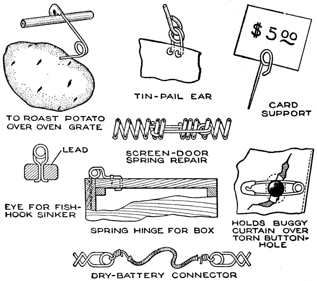
| TO ROAST POTATO OVER OVEN GRATE |
TIN-PAIL EAR | CARD SUPPORT |
| SCREEN-DOOR SPRING REPAIR |
||
| EYE FOR FISH- HOOK SINKER |
HOLDS BUGGY CURTAIN OVER TORN BUTTON- HOLE |
|
| SPRING HINGE FOR BOX | ||
| DRY-BATTERY CONNECTOR | ||
These Eight Examples of How an Ordinary Safety Pin can be Used for Practical Purposes Are Suggestive of Many Others
It is surprising to note how many uses can be made of an ordinary safety pin, both as an emergency-repair device, and for other purposes. I found 40 simple uses for safety pins, a few of which are shown in the illustration. Some of the many other uses are as a chain, a candle holder, a spring, a cover holder for a kettle, and as a pencil clip. Most of these can be made by twisting the safety pin with a small plier. By using a cutting plier, many more useful kinks can be devised.—George G. McVicker, North Bend, Neb.
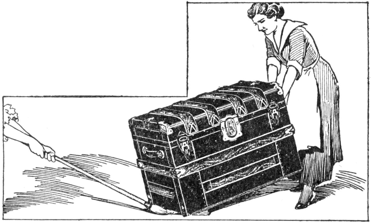
The Broom Is Slippery and Rides over the Floor or Even Carpets without Trouble
After trying to move a heavy trunk alone, the attempt is usually given up until some friend can be called in to lend a hand, because a truck or other means of handling such heavy objects is not at hand. An ordinary sweeping broom will serve as a sled to move a stove or similar object in the home without heavy lifting. The straw in the broom is slippery and can be drawn over carpets without injuring them. In handling a stove, the legs must of course be removed, one person drawing the load and the other steadying it.—Samuel H. Avery, Chicago, Ill.
[446]
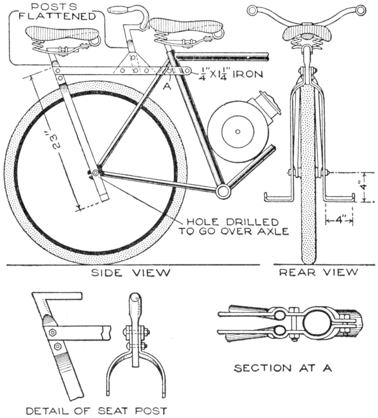
This Light-Weight Homemade Rear-Seat Fixture Is a Convenience for a Strong Bicycle or Motorcycle
A rear seat mounted on a light support that can be quickly attached to a strong bicycle or a motorcycle is handy, and one like that shown in the sketch can be made in the home workshop. The supporting frame, consisting of two main sections forming a fork over the rear axle, and a brace extending to the bicycle frame, are made of ¹⁄₄ by 1¹⁄₄-in. strap iron. The seat and the handlebars are supported on posts of the usual type, flattened at their lower ends, and riveted to the fixture. The lower ends of the fork are bent to form foot rests. The detailed construction of the seat post and the method of clamping the brace at A are shown in the smaller sketches. The fastenings on the seat and handlebar posts are made with rivets or bolts.—P. P. Avery, Garfield, N. J.
The front and rear wheels of a baby cab are usually of the same size and the tires on the rear wheels are worn much more rapidly than those on the front wheels. By changing the position of the wheels, the wear on the tires is equalized, making it unnecessary to renew them until all are worn out.—J. Cecil Alter, Cheyenne, Wyo.
The making of a billfold is easily within the range of an amateur in leather work, who will observe the instructions carefully. Seal, morocco, pigskin, and ooze sheep are satisfactory. Skiver, or thin leather, and silk moiré make suitable linings. When the processes involved in the making of the billfold are mastered, numerous other small articles in leather will suggest themselves, and can be made similarly.
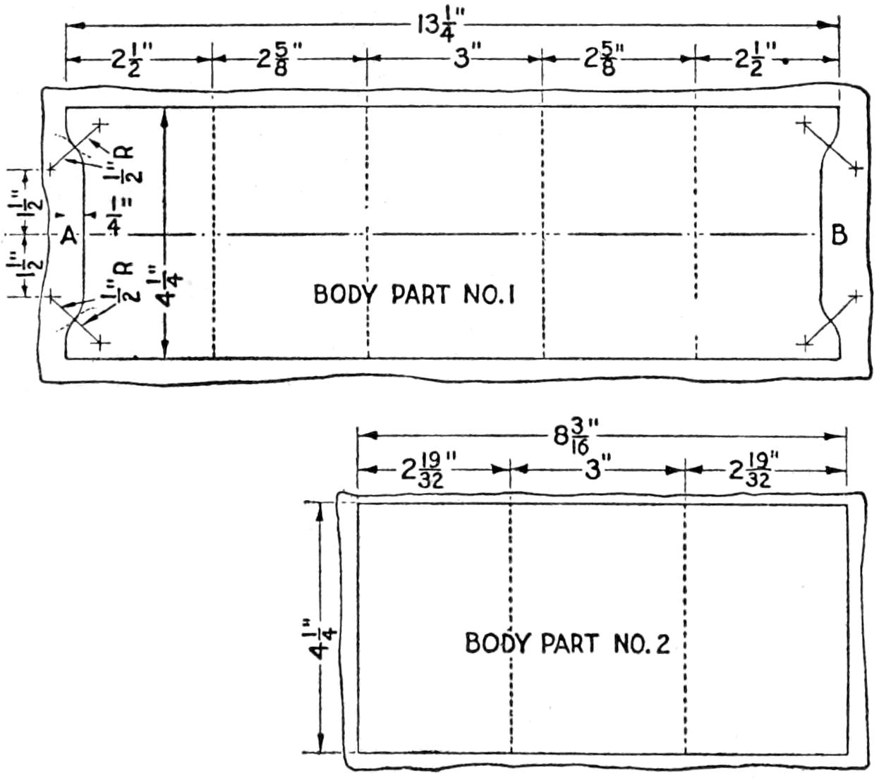
Fig. 1. Place the Pattern on the Leather and Trim It to Size Even with the Edges of the Pattern
The finished billfold is shown with the cardcase side up; folded, and with the bill compartment open, in Fig. 2. Begin the making of it by cutting a pattern of stiff cardboard for the main portion, or body part No. 1, as shown in Fig. 1.
Make a second pattern for body part No. 2, as shown in Fig. 1. Trim the leather to fit the patterns, a straight edge of metal being placed over the pattern as a guide for the knife. A[447] close-grained hardwood board, or a piece of sheet zinc, is suitable as a base for cutting the leather.
Cut pieces of lining slightly larger than the patterns. If skiver is used, it must be glued to the leather with a good quality of leather glue, which should be pliable so as not to crack the leather. Do not stretch the lining, but merely smooth it gently, as otherwise it may cause the leather to buckle. Place the glued parts under a light weight to dry. In fitting the silk lining into place, apply a thin stripe of glue around the edges only, and permit them to extend beyond the leather. Then trim them off neatly.
Part No. 1 is to be folded to form the back of the billfold and also the two pockets for cards. The parts are glued as shown in Fig. 3. Weight the billfold and permit the glue to dry. The sewing may then be undertaken.
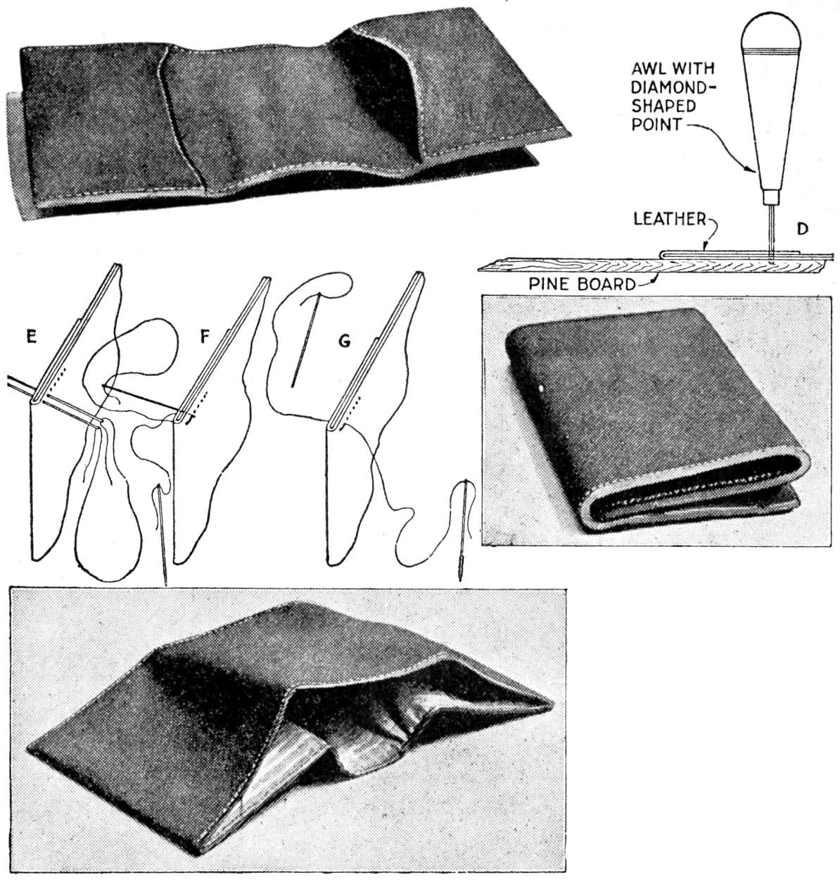
Fig. 2. The Photographs Show the Cardcase Side, the Folded Billfold, and the Silk-Lined Money Compartment
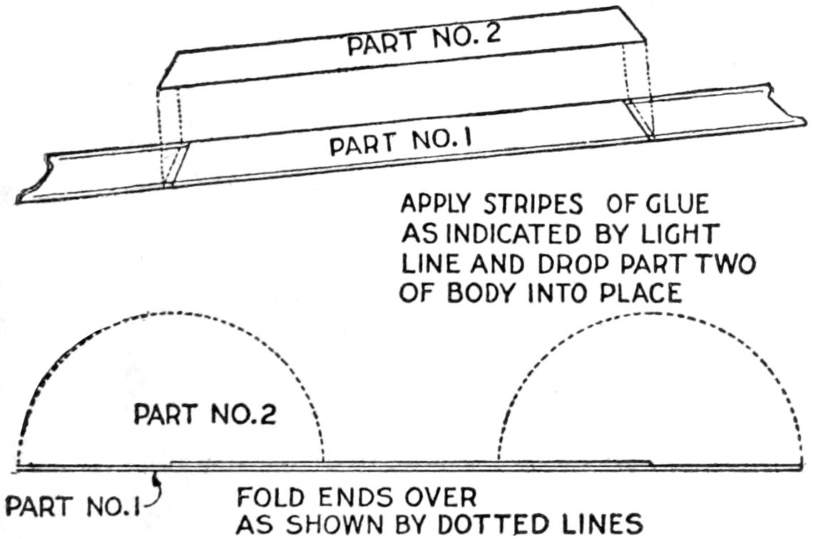
Fig. 3. Glue the Parts Together Carefully along the Edges, and Fold the Ends as Indicated
The neatness of the billfold will depend largely on the care with which the sewing is done, and the finish on the edges. Draw a straight line with a blunt-point tool along the edges to be sewed, ³⁄₁₆ in. from them. Mark the spacing for an inch of the stitches on a strip of paper and transfer them to the stitching line. Punch the holes, making certain that each is made with the awl held vertical, as shown at D. Back the open ends with strips of cardboard when punching holes in them. Heavy, waxed silk of a color to match the leather is used for the sewing. The work may be done by hand without a holder, clamped between two boards. Thread the two needles and start them from the right side, as at E. Pass the needle from the first hole through the second as at F. With the needles then in position, as at G, continue this stitch. Tie the ends of the thread neatly at the end of the stitching. Trim the edges and tool them to a smooth finish with a suitable metal tool, or rod, heated moderately, applying water with the finger tip.
¶The taper of a key is generally ¹⁄₈ in. per foot of length, and keys having a head are preferable because of greater ease in removing them. The width of a key is usually ¹⁄₄ the diameter of the shaft, plus ¹⁄₈ inch.
[448]
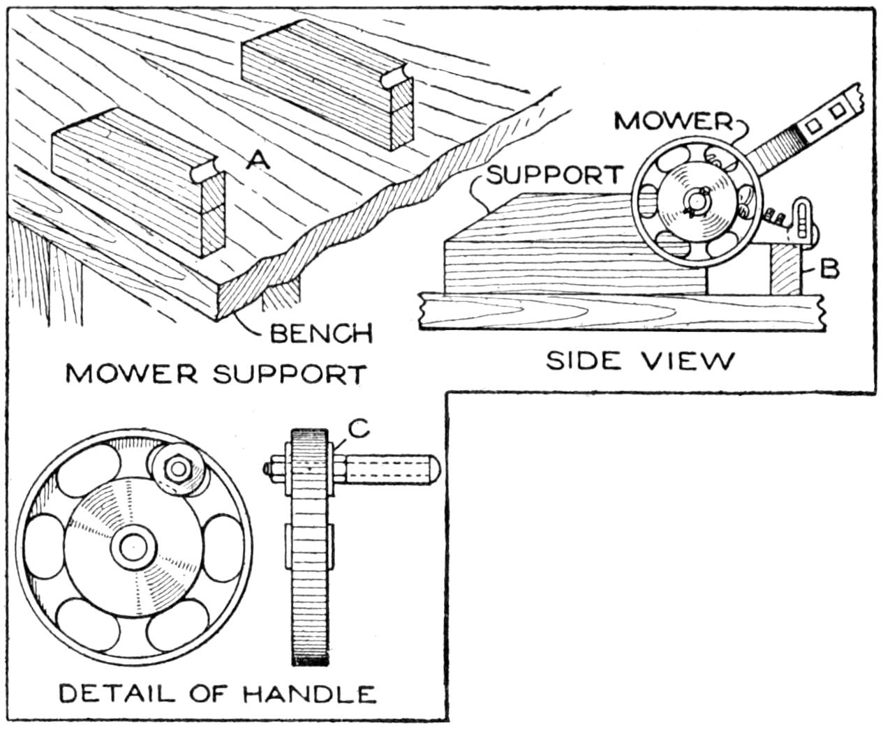
The Lawn Mower is Sharpened Quickly by the Use of This Rigging
With this device, one can quickly sharpen the lawn mower, or perhaps earn money sharpening the neighbors’ machines. Because several knives in a lawn mower work against the cutting blade, it is difficult to sharpen a mower satisfactorily with a file or stone. A usual method is to reverse the cutting-wheel cogs, turn the mower upside down, and run it backward over the ground. By the use of grinding paste on the cutting blade the cutting wheel tends to sharpen itself. This process can be improved by supporting the mower, as shown at A, the blocks permitting the mower’s driving wheels to rest outside them. A block, B, supports the wooden roller. Remove the driving wheels, and the gears which turn the cutting wheel. Take the gear from one end and put it in the other end, replacing the driving wheel. By revolving the latter backward, the cutting wheel will also turn backward. Apply a paste of emery powder and lubricating oil to the cutting blade, and adjust the blade so that it comes fairly into contact with the cutting wheel. Turn the driving wheel backward, and gradually tighten the adjustment until a good edge on the cutting blade and the knives is produced.
A handle fixed on the driving wheel, as shown at C, makes turning it easier. After sharpening, replace the gears, clean the bearings thoroughly, and replace the driving wheels.—Ed. M. Hawes, Everett, Wash.
The modern screw case for watches is primarily for the purpose of keeping dust from getting into the delicate works. Unless one is possessed of a strong grip, it is hard not only to set the case tight enough to keep out dust, but also to open the watch when adjustment is necessary. To make this work easy, a jeweler has, as a part of his tool kit, several rubber dies to fit the different sizes of watch cases. He made them from old rubber heels, cut to fit the watch cases closely. Danger of breaking the crystal is also overcome.—C. E. Drayer, Cleveland, Ohio.
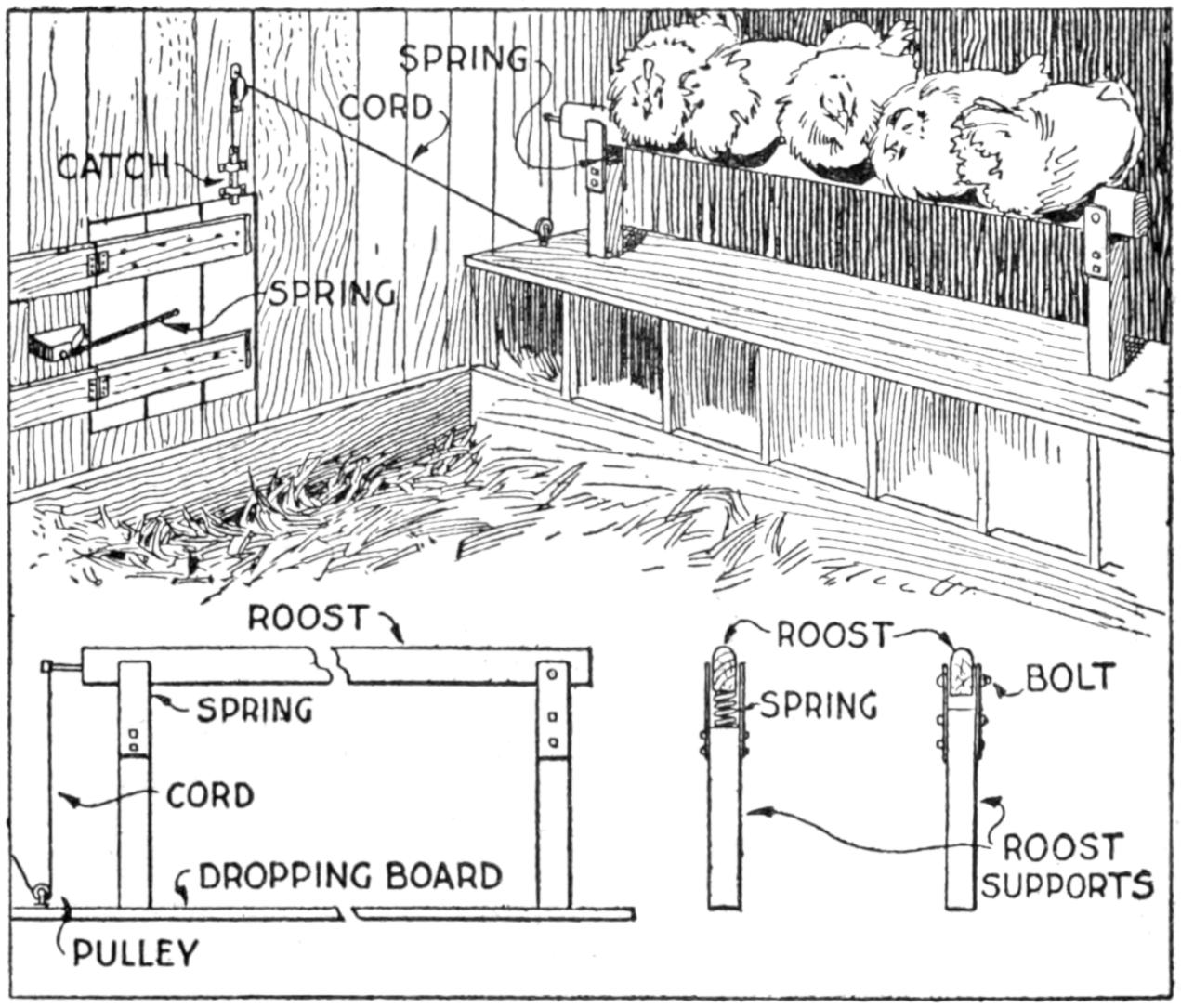
The Door is Opened Automatically When the Fowl Leave Their Roost
Those in the habit of shutting their poultry houses at night to prevent disturbance or loss by night-prowling animals, will be interested in a contrivance that makes this unnecessary. The principle of the mechanism, as illustrated is that the opening to the poultry house is closed after the fowls have gone to roost, and in the morning when they descend from the roost, the door automatically opens, and they are free to go out. The spring door opens inside with hinges at the side, and a suitable bumper. The spring has just sufficient tension to cause the door to open when the catch is released.
[449]
The roost is fitted up as shown in the detail. One end is held by a bolt, while the other rests on a coil spring compressed by the weight of the fowls on the roost. A cord is attached at the spring end, passing through pulleys to the door, where it is fastened to the end of the bolt catch. The door is closed after the fowls are on the roost. The spring end is compressed to a level position, by their weight. The instant the birds leave the roost, it rises and pulls the cord, releasing the catch, and permitting the door to open.—George S. Brown, Norwich, Conn.
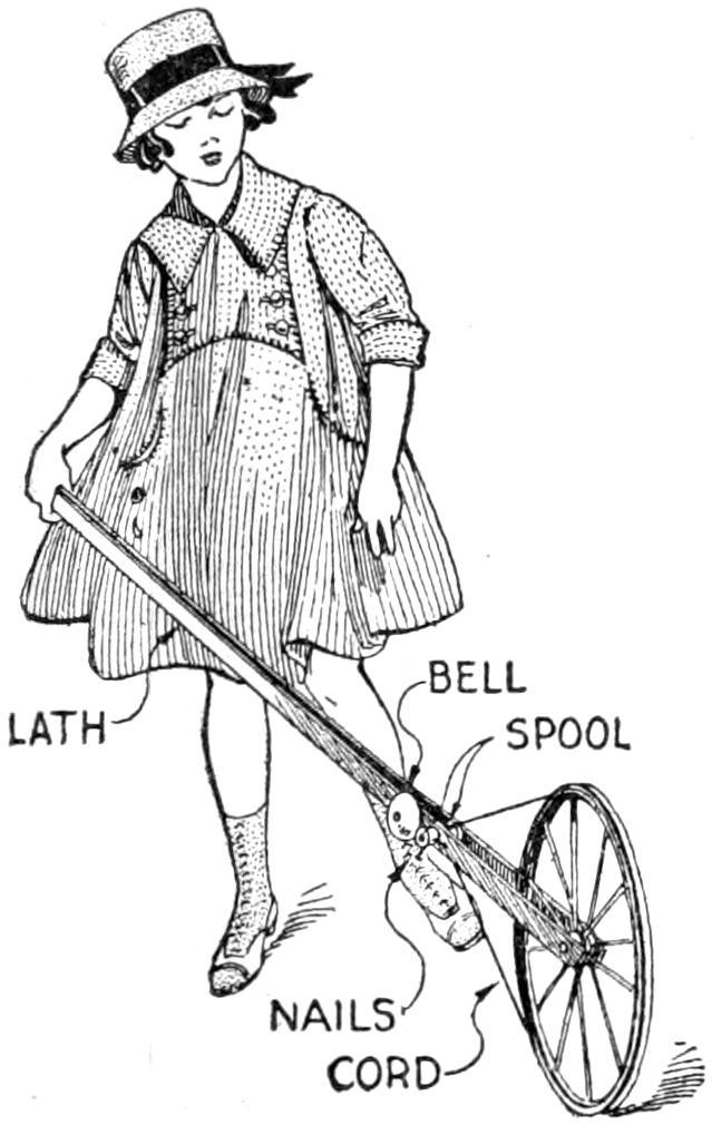
In making this useful toy, first, a wheel from an old baby carriage was stripped of the tire; then two laths are fastened together at one end, and the wheel inserted between them, at the other end, and held by a bolt. A strong cord was passed around the groove in the wheel, and around a spool, nailed so as to turn on the side of the lath when the wheel is rotated. Driven into the rim of the spool are three nails, which strike against the old alarm-clock bell, fastened as indicated.—W. F. MacGregor, Toronto, Can.
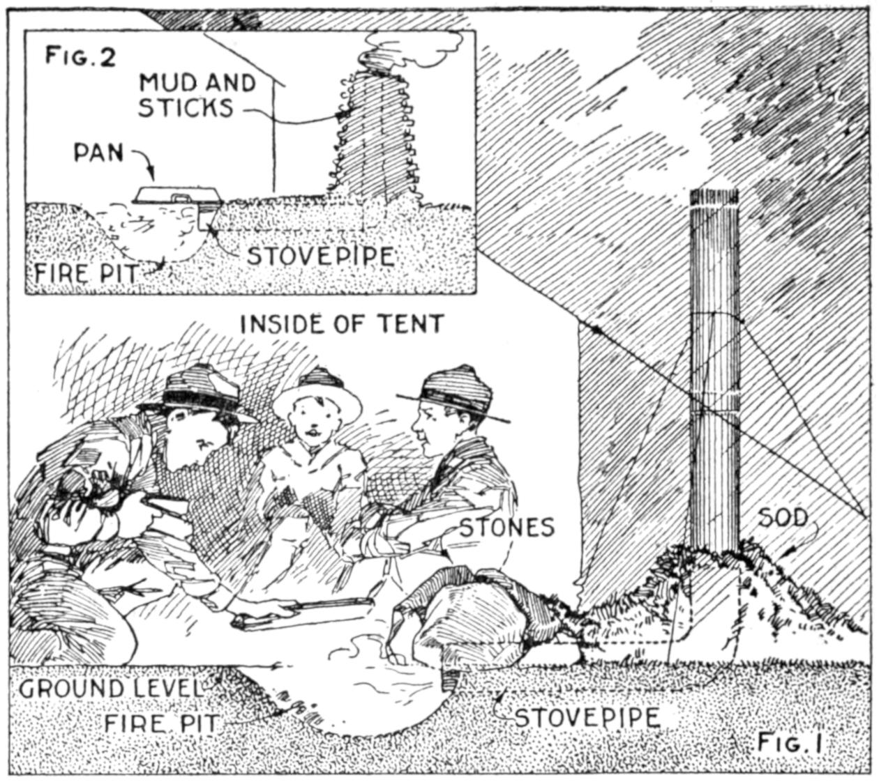
Boys at a Summer Camp Kept Themselves Busy during a Cold Spell by Making These Stoves
While conducting a boys’ camp in summer we experienced a severe sleet storm. Our tents were not equipped with stoves and I faced a double problem: to keep the boys warm and to keep them contented. The difficulty was solved by having them construct emergency camp stoves, as shown, using iron stovepipe, and other material at hand. One length of pipe is laid under the side of the tent about 4 in. in the ground, as in Fig. 1. An elbow mounted in sod connects with the chimney. A stone at the front of the stove regulates the draft, and stones placed upon the pipe hold the heat. The arrangement diagrammed in Fig. 2 is built with one length of pipe or a stone conduit. A hole is dug into the ground, about 10 in. deep. Over this is placed a pan, and an opening is made at the front for the fuel. The chimney is made of stones and sticks picked up around the camp, and plastered with mud. Coffee may be boiled or small cooking done on this stove.—William H. Leach, Alden, N. Y.
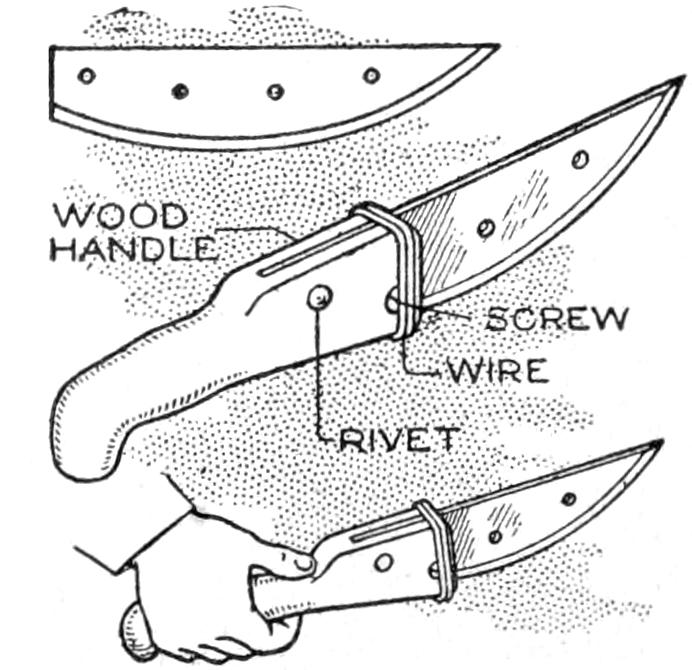
With the blade of an old beef cutter and a stout wood handle, I fashioned a brush knife that is superior to a sickle for cutting down heavy weeds. The blade was secured in a slotted handle by a screw and rivet, and the top of the handle wired as an additional security. A blade of this sort is handy, also, for pruning purposes.—J. M. Kane, Doylestown, Pa.
[450]
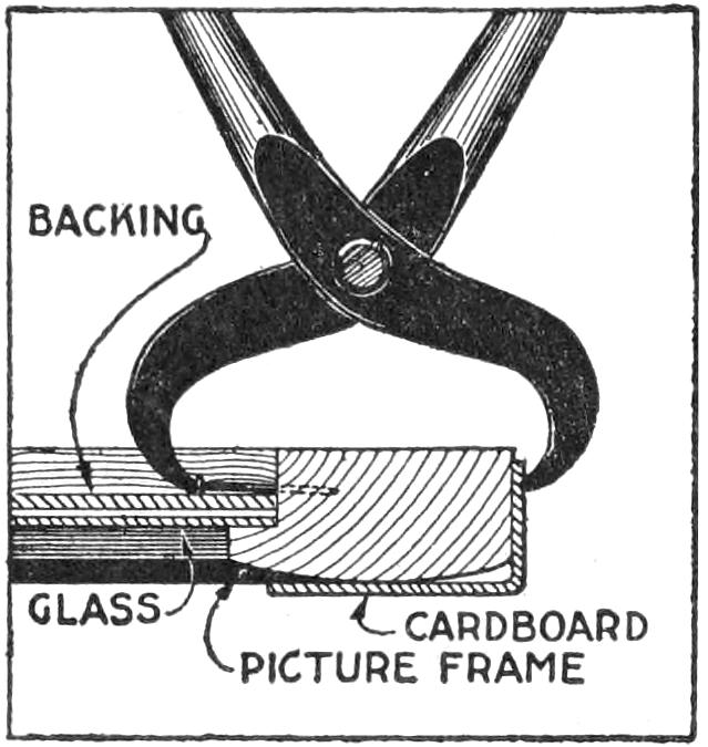
The fastening of a picture into a frame by the use of brads, or tacks, driven into the frame behind the backing is often done carelessly, because it is difficult to do a neat job with an ordinary hammer. A much better way of driving in these nails is to use a plier, as shown. Protect the edge of the frame with a layer or two of cardboard, and start the nail carefully, forcing it in by steady pressure on the plier handles.
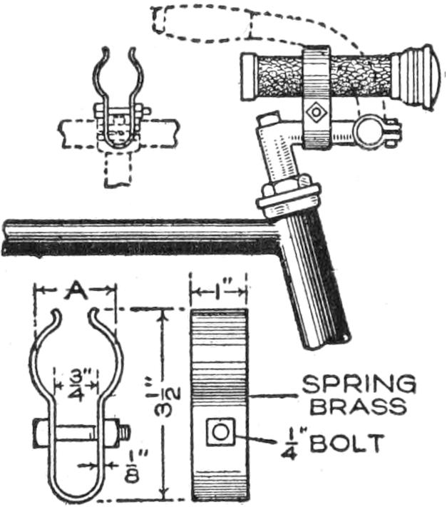
An ordinary pocket flash light makes a satisfactory headlight for a bicycle if fitted to the handlebar with a suitable clip. The arrangement shown makes it possible to remove the light quickly for use in the usual manner. The clip, as detailed, is of spring brass and is clamped over the post of the handlebar.—P. P. Avery, Garfield, N. J.
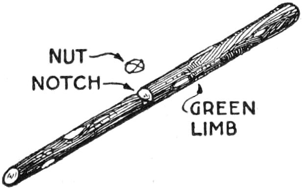
Most persons know what a difficult job it is to crack hickory nuts, unless provided with a suitable hammer, or other tool, for the purpose. When nut hunting, such tools are usually not at hand, and a method used by an old backwoodsman will be of interest. First he cut a hickory limb, about 2 in. thick and 3 ft. long. In the center of the limb, he cut a square notch, about halfway through, and just large enough to admit a nut. Then placing one end of the limb on the ground, the other end held in the left hand, he placed a nut in the notch, and bent the limb slightly. This brought the edges of the notch closer together, and cracked the nut neatly.—C. M. Vaiden, Portland, Ore.
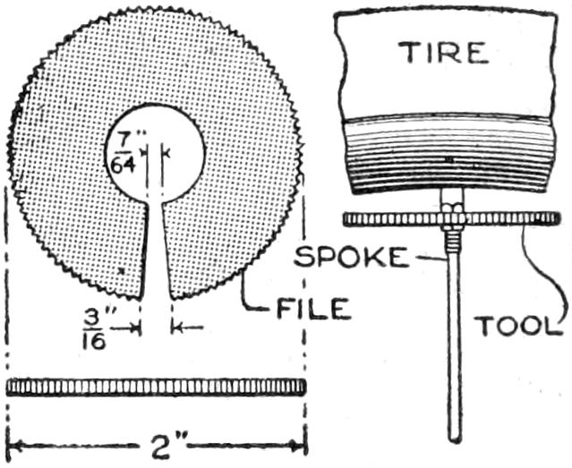
The wire spokes in bicycle and similar wheels often become loose, and a small pocket device for tightening them on the road is handy. A satisfactory one can be made quickly from a washer, 2 in. in diameter, cut as shown. A tapering slot is cut to the center of the washer to engage the nipples of various-sized spokes. The outer circumference of the washer is filed with a triangular file to provide a good finger grip.—H. E. Randell, Boston, Mass.
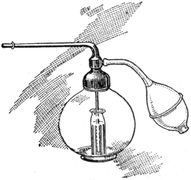
Atomizers are sometimes provided with delivery tubes the lower ends of which are ¹⁄₄ in. or more above the bottom of the reservoir, thus rendering useless considerable of the spraying liquid. To overcome this waste, in the case of expensive sprays, a small homeopathic vial was filled with the liquid from the bottom of the reservoir, and lowered into the bottle, as shown. The delivery tube of the atomizer was[451] set into the vial, and the cap screwed on. By this means almost every drop of the spraying fluid was utilized.—Carl L. Hartshorn, West Haven, Conn.
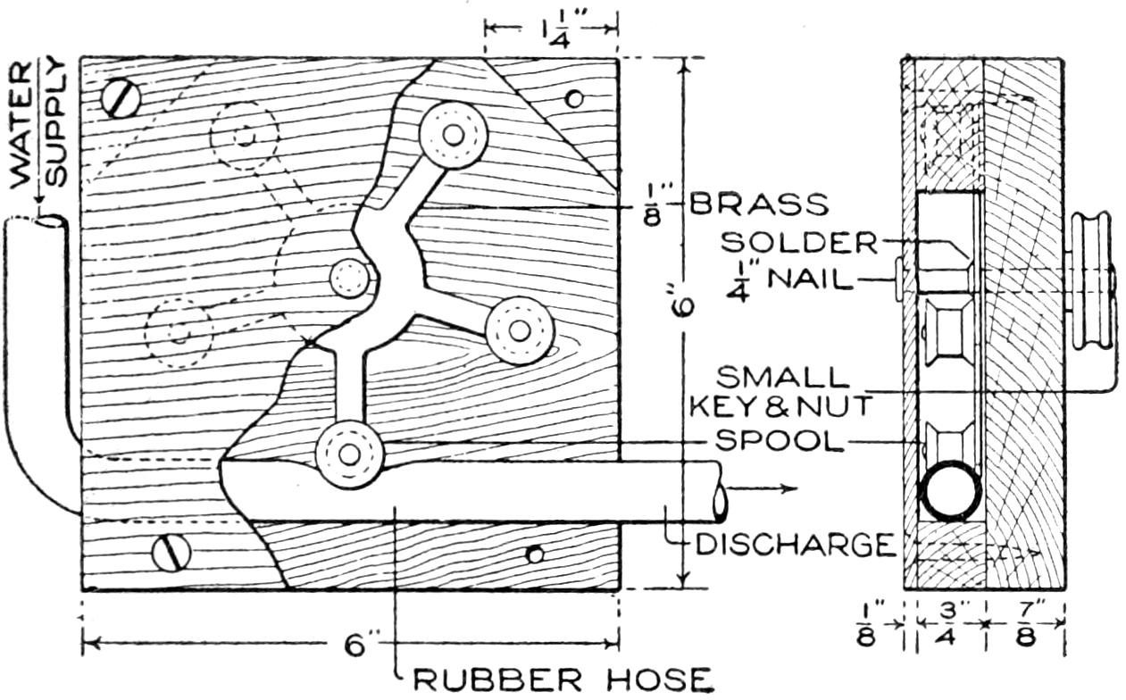
The Rotating Spools Press against the Water Hose and Force the Water from It at Increased Pressure
This small power pump is made from a block of wood, a piece of rubber hose, and a 5-arm rotor of brass, with small spools attached to it. The base of the casing is 6 in. square, and of ⁷⁄₈-in. wood. A ³⁄₄-in. triangular block is set at each corner, and a ¹⁄₈-in. cover of wood, fastened at the four corners with screws. A large nail is used as a shaft for the rotor, which is cut from brass, ¹⁄₃₂ to ¹⁄₁₆ in. thick. Small spools are mounted on the arms of the rotor, and the small pulley wheel is fixed on the end of the axle. The action is simple: As the rollers on the arms revolve against the hose, the force of the stream at the discharge end is increased, the device acting as a pump. Such an arrangement was used for moving targets in a rifle range, and can be built on a larger scale if desired. A small water, or electric, motor is used to drive the pump.—S. A. Hardy, St. Paul, Minn.
Type cases can be cleaned easily by using a bicycle pump, which will blow the dust out. Typewriters and other small machinery can also be cleaned this way. A long hose used with a foot pump is often preferable to the hand pump.
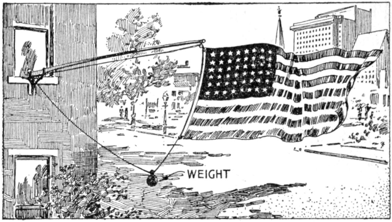
This Weighted Rope Permits the Flag to Fly in Its Natural Position
A householder devised a simple and effective method of keeping the flag upright when displayed from a nearly horizontal flagstaff. The cord which held the flag was run through pulleys, as indicated, and weighted with a pulley weight.—M. T. Kanary, Chicago, Illinois.
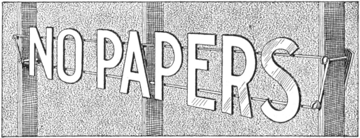
The Metal Letters were Quickly Made and Are Durable as Well as Neat
Needing a permanent sign to be mounted on an iron gate, I made one of metal, which is more durable and better-looking than most wooden or other common signs that the home mechanic can make. I used sheet metal and marked out the letters to cut them from the smallest possible strip, by reversing some of them. They were cut out with snips and chisels, and the edges filed smooth. The letters were then soldered to heavy wires, which were bolted to the gate by means of sheet-metal straps and bolts, as shown. The letters should be polished from time to time, especially if made from brass or copper.—Hugo Kretschmar, Brooklyn, N. Y.
[452]
The flexible rubber grips used on bicycles and motorcycles have good shock-absorbing qualities, but they have a tendency to break off at the end of the handlebar. They may be reinforced by a small stick projecting from the end of the handlebar tubing. One end of the stick is cut to fit tightly in the opening, and the other to fit the flexible end of the grip.—George M. Zimmerman, Fort Sumner, N. M.
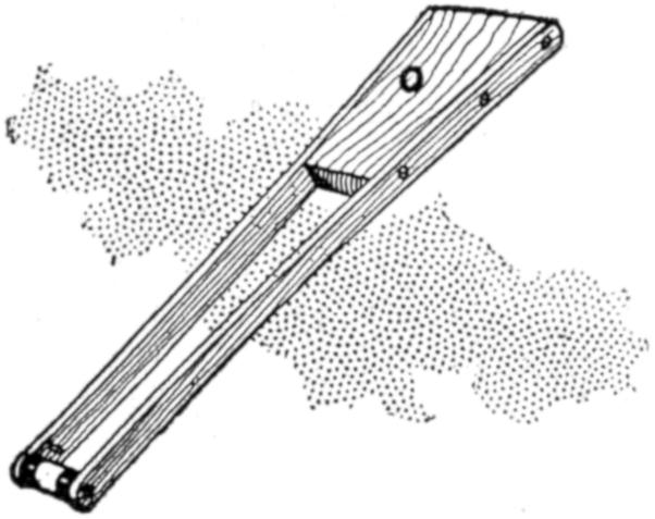
The amateur photographer who uses roll film and who does his developing by the tray method, will find this device a simple and reliable means for holding the film spool while removing the film, duplex paper, autographic carbon paper, gummed labels, etc. Once the spool is properly placed in the holder, there is little danger of its dropping. The holder takes various sizes of film spools. The side fingers are ³⁄₁₆ by ³⁄₄ by 23 in. long. A small peg is set in each finger, 1¹⁄₈ in. from the end, to engage the spool. The upper ends of the fingers are nailed to a tapered block of wood, ⁷⁄₈ by 3¹⁄₄ and 2¹⁄₂ in. wide, and 8 in. long. The holder can be conveniently fastened to a wall, door casing, or to the under side of a shelf in the dark room.—John Hoeck, Alameda, Calif.
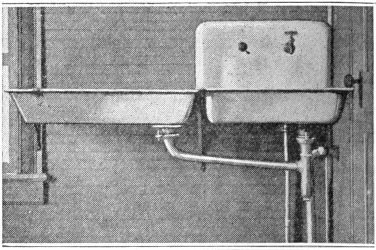
The Extra Sink Replaces the Drain Board and Does Its Work More Effectively
An added convenience for the housewife is the installation, in the place of the drain board customarily attached to the kitchen sink, of a second sink, with waste connections. Light wooden slats in the sink bottom give it all the utility of a drain board, without the danger of dishes slipping off onto the floor. A sink, of the old-fashioned kind used, can be purchased about as cheaply as a good drain board.—E. C. Blomeyer, Waco, Tex.
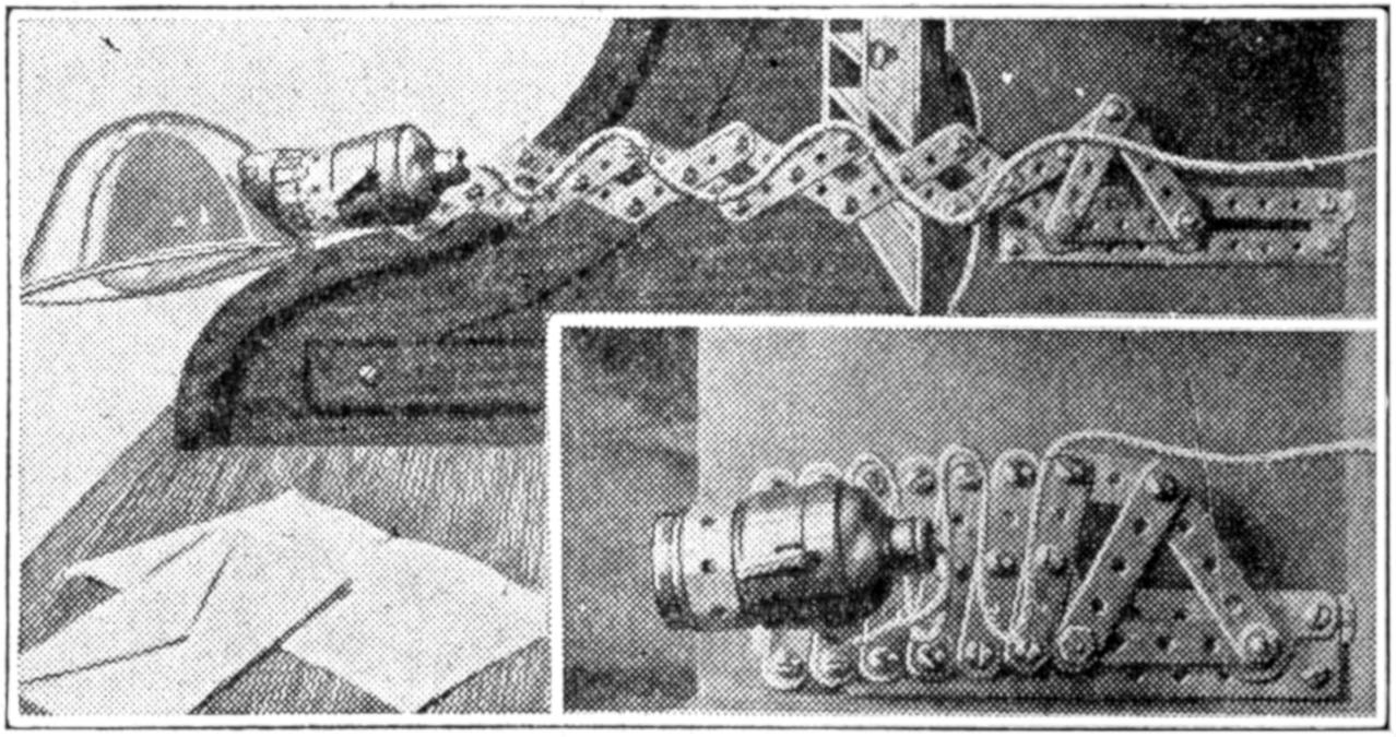
This Desk Lamp and Holder Folds Up into a Pigeonhole When Not in Use
The extension arm for an electric lamp shown in the illustration was made of strips from steel building toys. I installed it in my writing desk, and fastened it with one screw to the back of the desk inside the pigeonhole. When collapsed the arm measures 7¹⁄₂ in. from the fastened end to the front end of the socket, leaving only the globe protruding. Extended, it measures 16¹⁄₂ in. The lamp cord is taken through a hole in the back of the desk. If a very rigid arm is wanted, the strips can be doubled. I used screws with two nuts, but rivets can be used also, leaving the joints to move freely. The sliding feature at the inner end adds about 2 in. to the length of the arm when extended.—A. J. Viken, Waterloo, Ia.
[453]
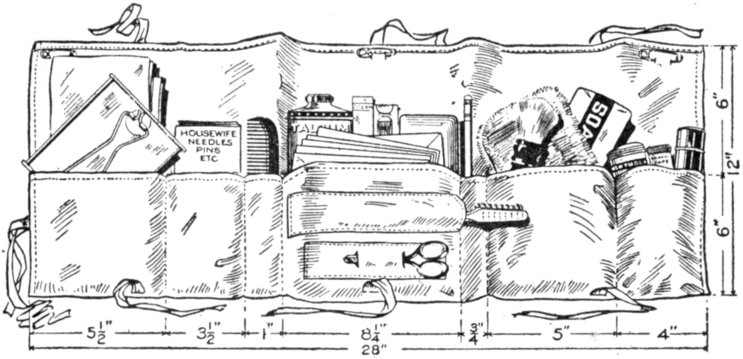
The Soldier Appreciates a Handy Folding Kit, Especially If the Girl He Left Behind Made It
A soldier’s kit approved by a colonel of the national guard because of its compactness, can be made easily of a band of khaki cloth. The kit, including the “housewife,” requires cloth, 27 in. wide. Cut 12 in. from one end for the housewife, which is 12 by 5 in. wide. To make the housewife, fold under the edges ¹⁄₄ in., and fold one end over 2¹⁄₂ in. and the other 1¹⁄₂ in. for pockets. In the larger center pocket can be placed court plaster, adhesive tape, photographs, letters, etc. Bind the edges ¹⁄₄ in., and form other pockets, as shown. The entire kit weighs 1¹⁄₄ lb. and can be carried by the soldier in his army blanket. The housewife, if necessary, can be removed and taken to the firing line. Handy articles to be fitted in the kit are mirror that can be hung up, comb, box of talcum powder, cold cream, tooth paste, pencil, wash cloth, soaps, shaving brush, toothbrush, and scissors. Three safety pins at the top of the bag enable it to be hung up in the tent. Strong binding tapes are sewed to the bag, and it can be folded handily in three sections.—Kate Thomen, Topeka, Kans.
It is not always necessary to keep milk and butter, or other foodstuffs, in refrigerator temperature to preserve hem, for 50 or 60° will often serve quite as well where the articles are to be consumed within a short time. To accomplish this slight degree of cooling, wrap a moist linen cloth, single thickness, snugly about the dish or package, and place it in a shallow pan of water, in an open window, out of the sun. The brick of butter should be placed on a support to hold it out of the water. The cooling is due to evaporation from the moist cloth. Not infrequently on a warm summer day, a thermometer with a bulb, wetted as suggested, will be 20° cooler in a breeze, than a dry-bulb thermometer.
¶A table of decimal equivalents, or other information can be mounted in shellac, at an angle to be easily read, at the head of a T-square, and is quite convenient.
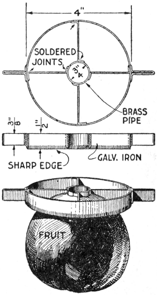
To provide a simple homemade device for cutting apples and other fruit into quarters and at the same time removing the core, the arrangement shown in the sketch was made. The circular frame is built up around a ring, ³⁄₄ in. in diameter, and the ribs and handles are soldered to it. A strip of galvanised iron, ¹⁄₂ in. wide, was used for the cutting portion, and the lower edge was filed sharp, and then finished with a small oil stone. In use, the cutter is set over the fruit, as shown, and by pressure on the handles, it is cut neatly.—L. N. Brown, Baltimore, Md.
[454]
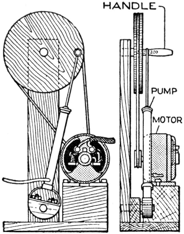
To make this motor-driven pump, which I use with considerable success, I fitted a bicycle foot pump to a stand, arranging it to be detached quickly. A 4-in. wooden disk was cut in two, and one-half bolted to the stirrup of the pump. A wheel, 14 in. in diameter and 2 in. thick, was mounted on a 2 by 6-in. support, as shown. A crankpin at the outer edge of the large wheel was connected to the plunger of the pump. The latter may be run with an electric motor, belted as indicated, or with other power. I use a small homemade water motor described in “Shop Notes,” with excellent results.—R. S. Matzen, Fort Collins, Colo.
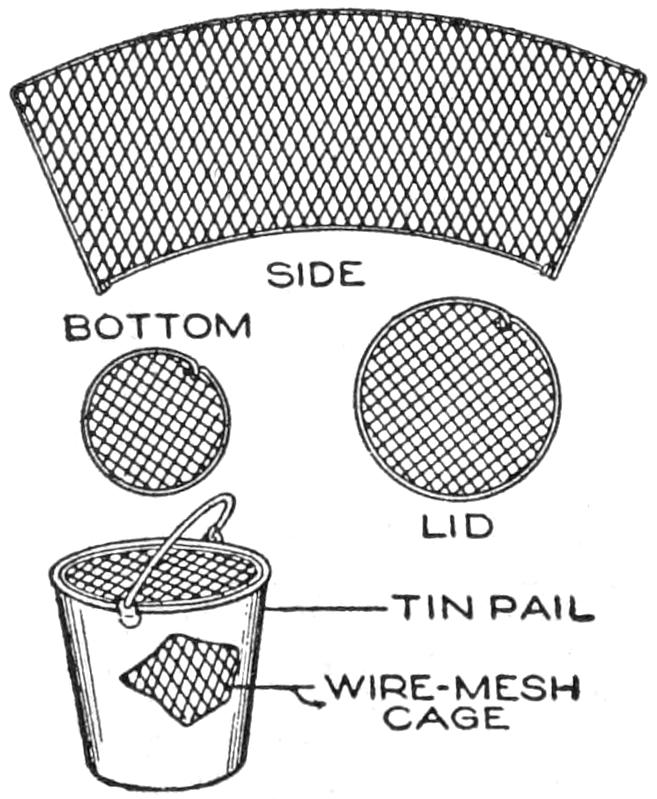
Oftentimes the fisherman takes a pail along on a fishing excursion so that he may bring back his catch alive, to put it in a water tank, or to keep the fish fresh. The water in an ordinary pail soon becomes stale, and the fish may die before he reaches home. They should be kept in the water of the lake or stream until the fisherman goes home. A good means of caring for them, superior to the common string, is to make a wire-mesh container, to fit inside the water pail, as shown. The mesh form can be lifted out, carrying with it all of the fish in the pail, and be set in the fresh water.—Dale R. Van Horn, Milton, Wisconsin.
The side member of an automobile-truck frame was overstrained, and started to sag. To replace it with a new channel piece was out of the question, so it was decided to repair the trouble. A piece of ³⁄₁₆-in. plate steel was cut to the proper length, in a truss-shape, wider at the middle than at the ends, to carry the load properly. It was riveted to the strained member by means of ⁵⁄₁₆-in. round-head rivets, and prevented further sagging.
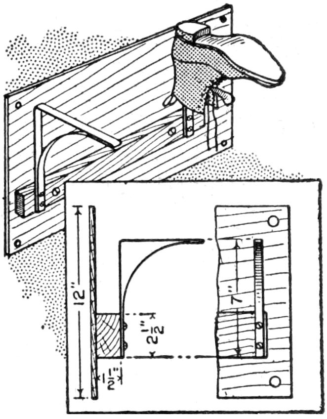
Footgear is injured when not properly dried out after use in water or in rough weather, and to care for the shoes, rubbers, etc., I made a rack fitted behind a stove on which they are dried out quickly and thoroughly. The rack consists of a row of brackets made of strap iron, bent as shown in the sketch, and the shoes are slipped on them. The brackets are mounted on a strip of wood, which is fastened to the wall with screws. A thin piece of board or sheet metal protects the wall.—Edgar Morgan, Robbinsdale, Minn.
Scissors will wear better and keep their cutting edges longer, if they are kept hanging up with the blades apart when not in use. The better-grade scissors, especially the longer pairs, are made with each blade slightly bowed, so that in cutting, the edges cross at an angle near the cutting point. Keeping them closed tends to weaken the springiness of the blades, and the points are worn by contact under tension.—John M. Bonbright, Philadelphia, Pa.
[455]
The boy who likes to play games in which the lead soldier and other features of imitation warfare have a part, can make his own lead soldiers, and other castings, by the use of a plaster-of-Paris mold. If he cannot undertake this work alone, the process is interesting for his older brother, or even for “daddy.” A mold of plaster of Paris, as shown in the illustration, is used for the casting box. The hollow impression of the soldier is filled with the molten lead, which is poured in through the sprue hole at the top. When the lead cools, the mold is opened, the casting removed, and the process repeated. An entire army can thus be made with a single mold.
First obtain a small lead soldier, and coat it with shellac. Make a box somewhat larger than the pattern for the soldier, as shown in the sketch. Make it about 1¹⁄₂ in. deep, and set bolts near the corners, as shown, pouring the plaster around them. Fill the box half full of plaster of Paris. While still soft, press the pattern into the center of the plaster so that half its thickness is imbedded. Permit the under mold to dry, and remove the pattern. Shellac the surface of the plaster and the impression. Wrap a layer of oiled paper around the bolts. Replace the pattern in the impression and fill the remaining half of the box with plaster, and permit it to dry.
Also make a small wooden plug, and set it in the center, its point touching the pattern, and pour the plaster around it. When the mold is dry remove this plug, thus forming the sprue hole, through which the molten lead is poured into the mold.
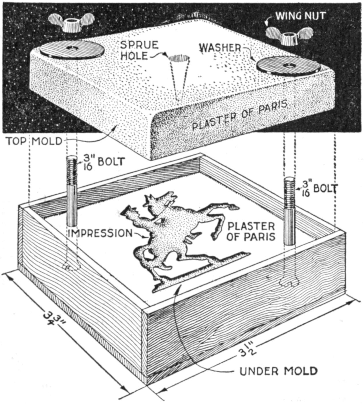
Lead Soldiers, and Many Other Small Castings, can be Made by the Use of This Plaster-of-Paris Mold
When the second part of the mold is dry, lift it carefully from the under mold, and remove the pattern. Shellac the surface of the top mold, cleaning away any small bits of plaster around the edges. Trim down the box so that the top mold projects over it about ³⁄₈ in., making it easy to drop the top mold into place over the bolts. To use the mold, make certain that it is clean inside and set the top into place. Fasten down the wing nuts at the washers. Be very careful that the mold is dry, as hot metal poured on a wet surface may cause a dangerous splash. Repeat this process, and if care is taken about 300 castings can be made with one mold. The soldiers can be painted suitably and even sold in sets. The process can be adapted to many forms of other small castings, using other suitable metals, or wax, where the casting is to be molded into shape further.
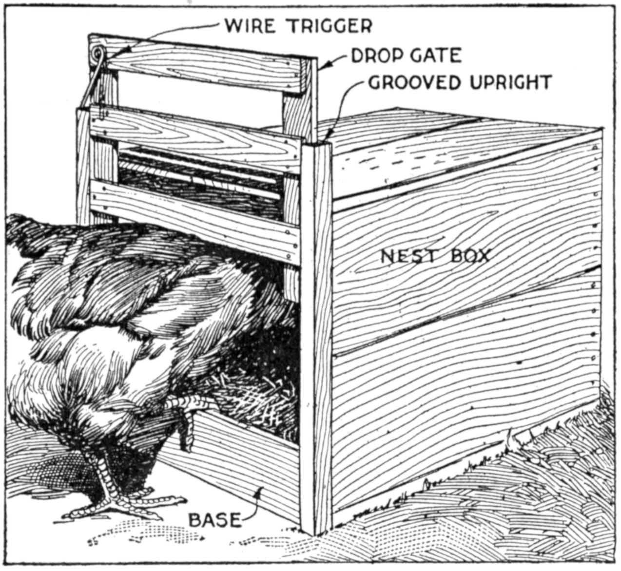
The Trap Nest Automatically Closes as the Hen Enters the Nest Box, Releasing the Trigger
Poultry raisers find a trap nest useful, and one can be made quickly by fitting an old packing box with a suitable sliding gate. In the arrangement shown, the gate is raised slightly as the hen enters the nest box, releasing the spring and causing the gate to drop.[456] The gate and spring can be adjusted to various-sized breeds of poultry. The two grooved uprights can be cut from flooring and the other wooden parts made from laths or wooden strips. The trigger is made of wire.—A. J. Call, Hartsville, Mass.
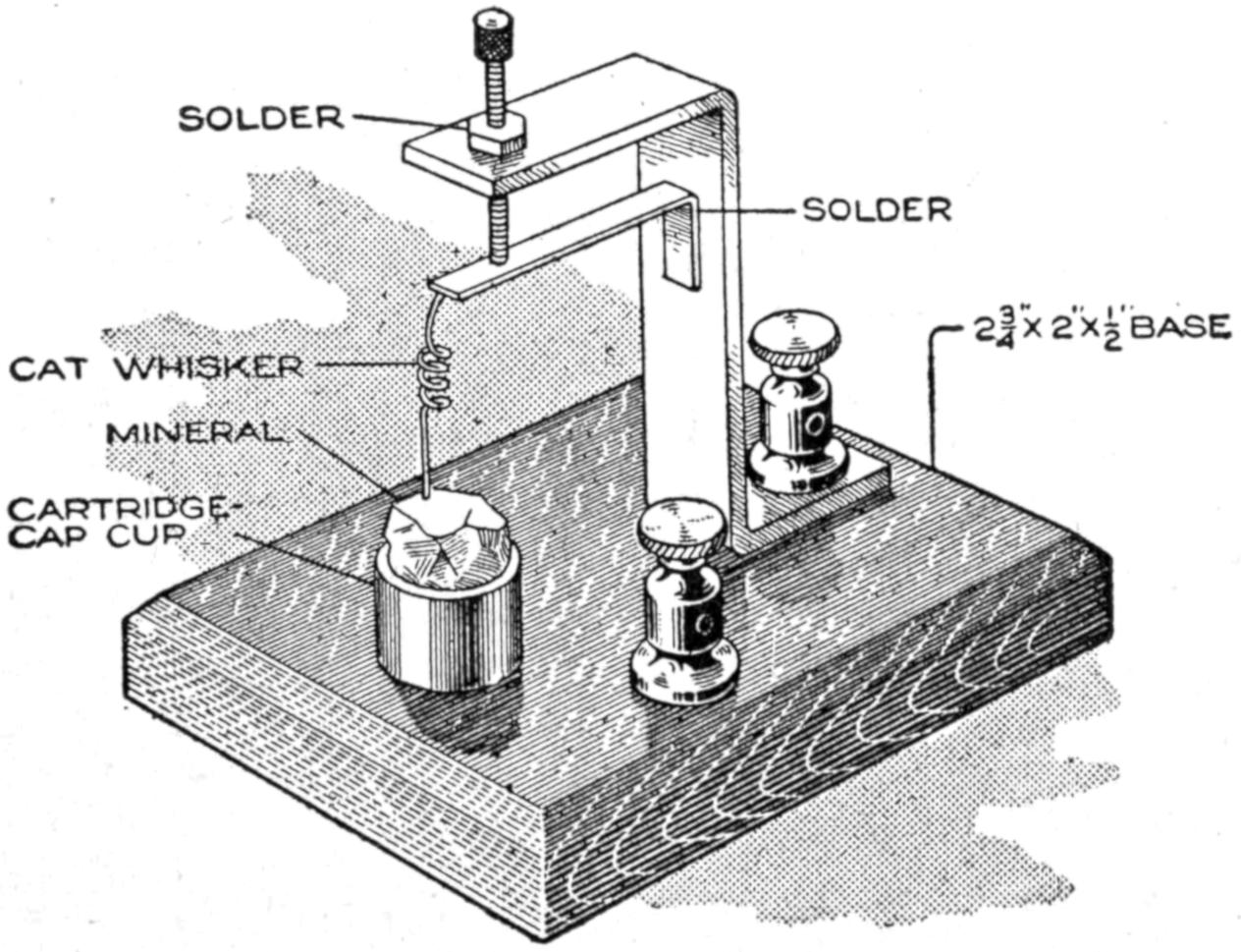
This Neat Wireless Detector was Made of Materials Easily Gathered in the Boy’s Workshop
A cheap and serviceable wireless detector was made from odds and ends such as any amateur can obtain. The base was made of wood, saturated in paraffin. The mineral cup is a brass cap from a cartridge fuse. The upright was made of a piece of copper, ¹⁄₂ by 4¹⁄₂ in. long, and is fastened to the base by an old-battery binding post. The spring which supports the cat whisker is made of a strip of copper, ¹⁄₃₂ in. by ³⁄₁₆ in. wide. The cat whisker is soldered to the spring, and the spring is bolted to the upright. The setscrew, which regulates the pressure of the cat whisker upon the mineral, works in a nut, soldered over a hole in the top of the upright. The cat whisker is made of No. 22 gauge bare copper wire. The connection between the cup and the battery binding post, at the front edge, is made on the under side of the base.—Charles Brinkmann, Chicago, Ill.
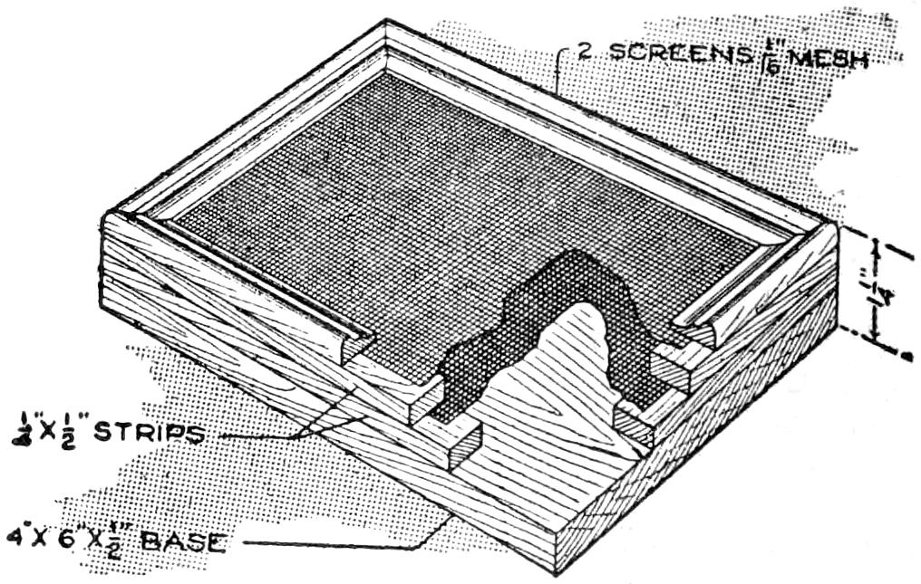
Pins Placed in This Durable Desk Pincushion Arrange Themselves in Vertical Position, Head Up
Pins placed in a pincushion like that shown automatically arrange themselves vertically, head up, so that they may be removed handily when needed. The pincushion is durable, and a useful device for the desk. It is made by binding two layers of ordinary screen wire between wooden frames, mounted on a wooden base, ¹⁄₄ in. thick, 2¹⁄₂ in. wide, and 3¹⁄₂ in. long. The frame can be finished neatly, and made of hard wood to match other desk fittings.—D. J. McKean, San Francisco, Calif.
When a sheet of paper, a drawing, or a blueprint becomes curved or warped, it is annoying to use the sheet unless it is straightened. An easy method of doing this is to lay the sheet flat on the edge of a drawing board or table and draw it down over the edge, the hand pressing down on the paper, stretching it out. This, repeated several times, will soon smooth a much-curled sheet.
[457]
If the band that draws the typewriter carriage should break, the operator can continue to write until proper repairs are made by a temporary substitute for the spring tension. Tie a string to the carriage, where it will not become entangled in the mechanism, and attach a weight, about equal to the pull of the spring, to the string. Let the weight hang over the edge of the desk, to the left of the machine. It will pull the carriage along, as does the usual tension device.
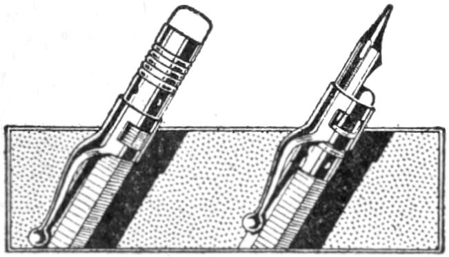
An ordinary pencil clip can be used to make a practical penholder by sliding it to the end of the pencil, as shown, and inserting the pen under it. The tension of the clip holds the pen firmly, and provides a serviceable holder, for emergency use, or even for permanent use, where a pen and pencil combined are desired.—Raymond B. Rogers, Portland, Ore.
Rigging up a small dynamo on the bicycle is a simple job, the dynamo being belted from a friction pulley, making connections with the rubber tire of the rear wheel, as shown. Fig. 1 shows the make-up of the head lamp. It is composed of a tin cylinder, grooved at one end to hold the lens; at the other end of the cylinder is fastened a ³⁄₄-in. wooden disk, to which the lamp socket is fixed. Clamp straps hold the lamp on the fork frame. The small lamp, inserted in the socket, holds the reflector in place.
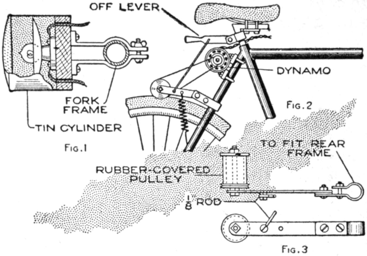
Fig. 1 Fig. 2
Fig. 3
The Dynamo is Operated by a Belt Arrangement Connected to the Rear Wheel, and Supplies Light, and, if Desired, Operates a Horn
The dynamo-driving arrangement is shown in Fig. 2, and detailed in Fig. 3. A leather belt fits in the groove side of the wooden pulley. The swinging pulley arm supports and clamps the driving arrangement. A spring holds the friction wheel against the tire, and to release it, the “off” lever is used. A small direct-current dynamo serves well, and may also be used to operate the horn and whistle.—G. F. Thompson, Pittsburgh, Pa.
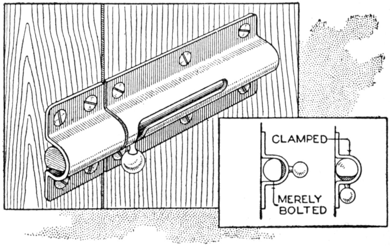
The Eccentric End on the Drawbolt Holds the Door Firmly, Preventing Rattling
A simple method of preventing a bolted door from rattling, by forcing it against the doorstop, or a weather strip, by means of an eccentric filed on the socket end of the bolt, is shown in the sketch. The bolt is fitted closely to the door and casing, and, when the bolt is turned so that the eccentric end is in action, the door is forced firmly against the doorstop.—C. H. Chambers, Schenectady, N. Y.
[458]
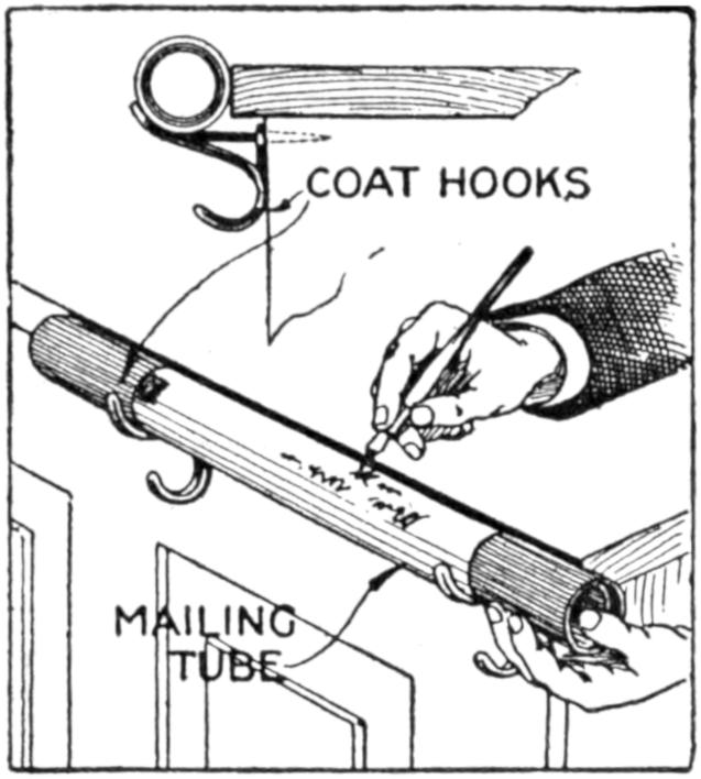
The job of addressing a large number of mailing tubes is an awkward one, unless the tube is set so that its upper edge is on a level with the hand. A convenient method of doing this, and a kink which is permanently useful where mailing tubes are to be addressed from time to time, is to arrange ordinary coat hooks at the side of the desk near the front corner, as shown. The tube is placed on the hooks, its upper edge even with the top of the desk, making the writing of the address as handy as in writing ordinarily.
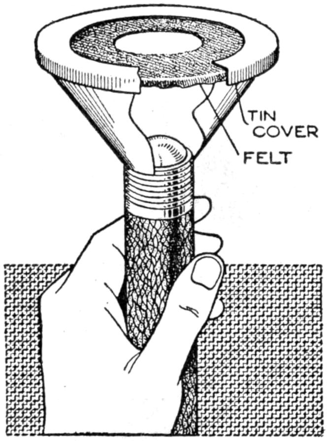
A pocket electric flash light can be easily used for testing eggs if equipped in the following manner: Take an ordinary tin funnel and cut off the spout so the small end will fit snugly over the lens of the flash light. Prepare the larger end of the funnel to accommodate a tin-can cover, so the cover will fit tight. Cut out the face of the cover, leaving a ¹⁄₂-in. rim all around, and file the edge. Then cut a 1-in. hole in a piece of felt, place it over the large end of the funnel, and force the cover over it. This may be quickly slipped on and off the flash light and carried in the pocket. The egg to be tested is placed on the felt, over the opening, and the lamp held vertically, the operator looking down on the egg.
It is usually disappointing to the amateur photographer, when taking pictures of groups of which he is a member, not to be able to be in the pictures. However, most amateurs can construct a release arrangement, in a few minutes, that operates with satisfaction. A clothespin of the clip type is used. The spring should be weakened by bending it from the wood, so that it has just enough tension to bring the jaws of the clothespin together without a snap. Whittle the inner sides of the handles, as shown, so that the jaws accommodate the plunger of the shutter. Then saw a slot in the handles, ¹⁄₄ in. deep and ¹⁄₈ in. wide. Drill a ³⁄₁₆-in. hole in the whittled depression of one of the jaws, and cut a ¹⁄₈-in. slot to it, as shown. The small trigger piece is cut of hard wood. It should fit its slot snugly, at the other end of the pin.
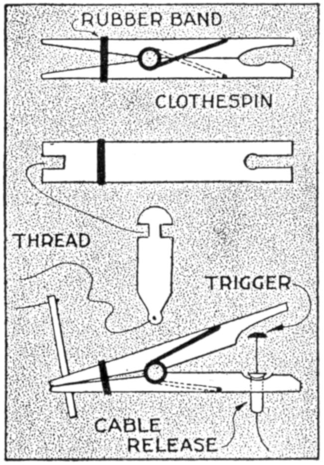
The release device is operated as follows: Slip the plunger tube, with the shutter release cable, into its slot. Keeping the jaws wide open, place the trigger in the slots of the two compressed handles. It is only necessary to jerk a thread attached to the trigger to free the two handles, which in turn snap the plunger. If the tension on the jaws is too strong, put a rubber band around the handles to act as a check.—Werner W. Baumeister, Walla Walla, Wash.
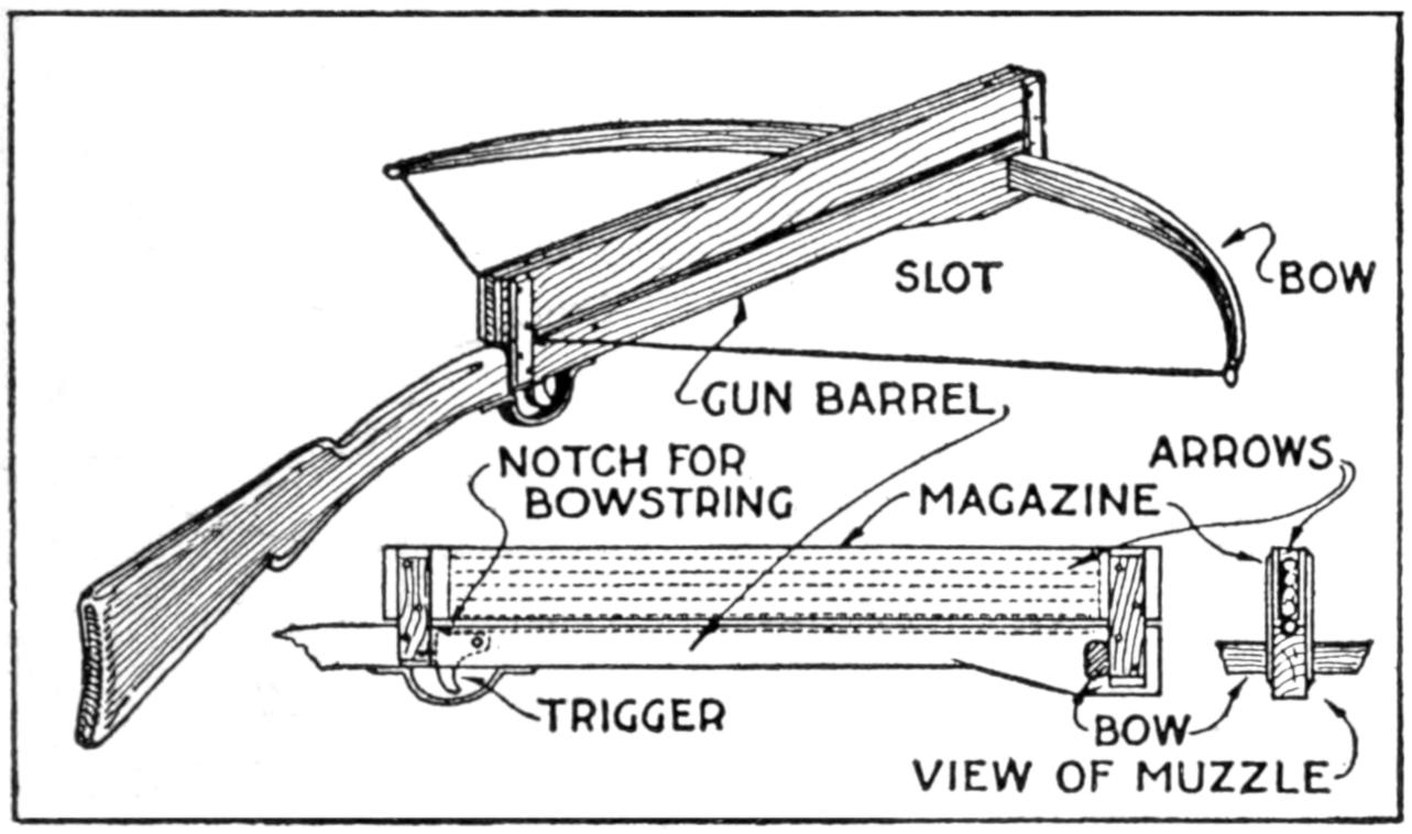
The Arrows are Stacked in the Magazine and Fired in Succession by the Bowstring Released at the Trigger
A new type of bow gun that a boy can make, and which will give him plenty of good sport, is one of the repeating or magazine variety. To make the gun, cut a soft pine board, 40 in.[459] long and 5 in. wide. With a saw and knife, cut the gun form as shown. Cut a groove along the top of the barrel, where the arrow will lie ready to be shot out when the hickory bow is released. The magazine holding the five arrows is made of thin boards, 24 in. long, and is held in place by four small strips. The magazine is 3 in. deep, thus permitting the five arrows to lie evenly in it without crowding. The bow is of seasoned hickory and is set into the end of the barrel. The notch in which the bowstring catches, should be cut just under the rear end of the magazine. The trigger is an L-shaped, pivoted piece, and pushes the cord off the notch when ready to fire. As soon as the first arrow leaves the gun the one just above it drops down into the groove when the bowstring is again pulled back into place behind the notch. Pressure on the trigger shoots this arrow, another takes its place, and the cord is pulled back once more. The arrows should be of light pine, 22 in. long and ¹⁄₂ in. square, the rear end notched and the front pointed. To make the arrow shoot in a straight course, and to give it proper weight, the head end should be bored with a ³⁄₁₆ in. bit, 3 in. deep, and melted lead run into the hole.—E. F. Dalton, Cincinnati, Ohio.
¶Ruling pens often work improperly, or have a tendency to cut the paper because of tiny feather edges at the points. These should be carefully honed and stropped off.
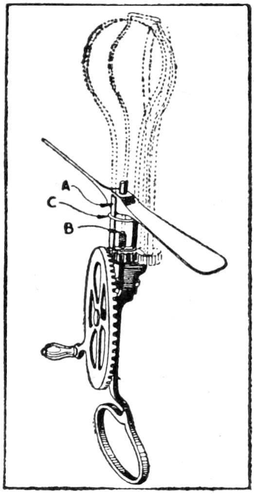
One of the features which take the joy out of flying elastic-driven model aeroplanes is the time taken to wind them up. For 10 cents and very little work a fast winder can be made out of an ordinary geared egg beater. Remove the outer small pinion and the revolving beater attached to it. Then cut the other beater off at A, as shown in the sketch, and the spindle at B. A few turns of tinned wire soldered to the spindle will keep the pinion from sliding off. Another piece of the same wire may be soldered to the two arms, at C, to strengthen them. In use, the hub of the propeller is inserted between the two arms, as indicated and the rubber wound.—Morris G. Miller, New Rochelle, N. Y.
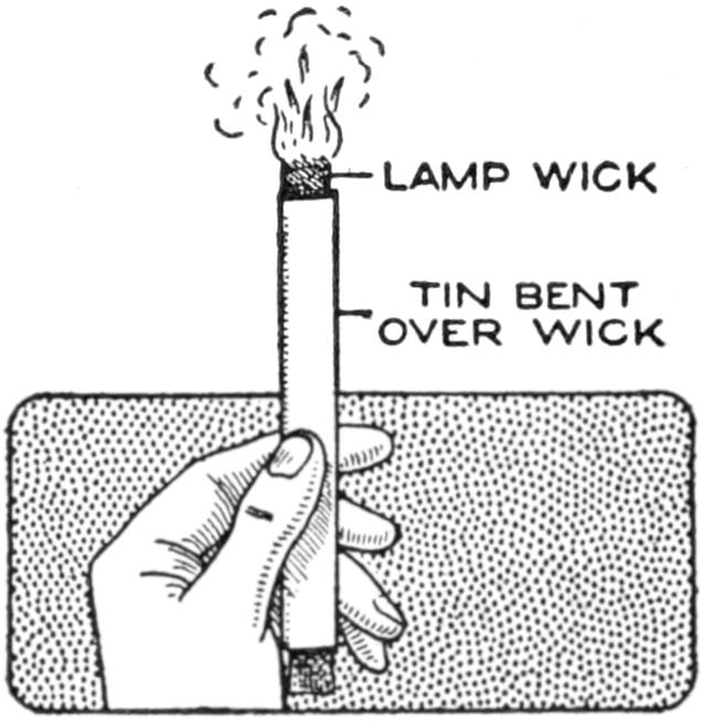
A stove lighter for gasoline or similar stoves can be made quickly. Cut a piece of tin, 7 in. long and 1 in. wide. Place a lamp, wick on the tin so that a part of it projects from the end of the tin. Fold the tin so that the wick is held, but so that it can be drawn out when needed. Saturate the wick in kerosene, or other thicker oil. When wishing to light one or more burners of the stove, light the wick and apply it to the burners. The stove can be lighted with less danger of burning the hands than when a match is used directly.—Lee M. Delzell, Maroa, Ill.
[460]
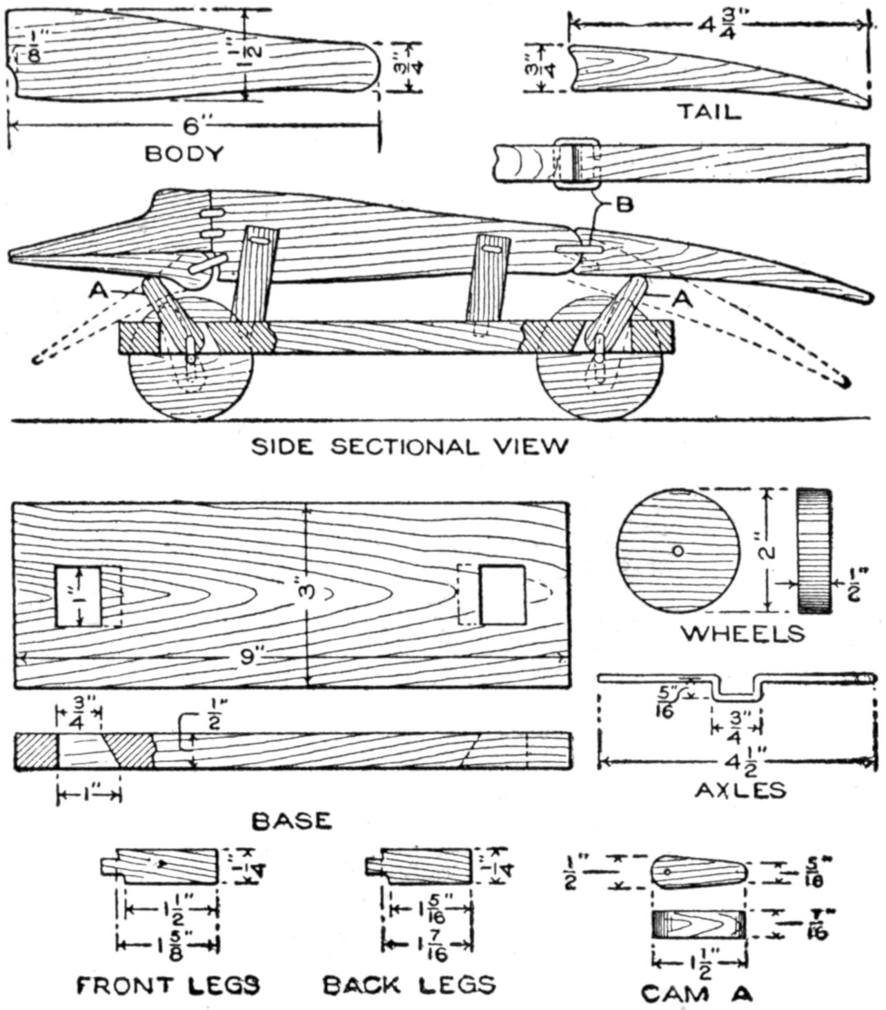
The Alligator is Drawn Along with a String, and the Jaws and Tail Flip Up and Down
A toy alligator that opens its mouth and wags its tail as it is pulled along can be made of wood by a boy, with a jackknife. The various parts, as shown, are cut from soft wood, ¹⁄₂ in. thick. The method of fastening the parts is shown in the side sectional view. When the wheels turn, the cams A, set on the crank portions of the wheel axles, raise and lower the jaw and tail. The upper jaw is 1 in. wide at the widest part, and 3 in. long. The lower jaw is smaller, and the same length. The body is 6 in. long, and tapering in width from 1¹⁄₂ to ³⁄₄ in. The tail is 4³⁄₄ in. long, and ³⁄₄ in. wide. Holes are drilled in each piece near the edge, at joining points, through which wires are drawn, and clamped, as at B. The legs are shown in detail. They are attached to the body by drilling a ¹⁄₁₆-in. hole in each, and a hole through the body, through which the fastenings are passed. The lower end of the legs are fastened to the base, which is 3 by 9 in. long. Square holes, 1 in. wide, near each end, are provided for the cams A. The axles and wheels are made as shown. The axles fit tightly in the wheels, so that the latter can move the axles around with each turn. The axles are made from ¹⁄₈-in. wire, bent as shown, and should be long enough, after passing through the bottom, to extend through the wheels on each side.—Charles C. Wagner, Los Angeles, Calif.
Frequently, in placing a coil spring on a screen or other door, the casing is flush with the door, and it is difficult to give the spring the desired leverage. If it is attached to the casing directly, the surface is marred by the rubbing of the spring. A good method is to set a small iron bracket, either homemade of strap iron or one of the commercial type, on the casing and attach the end of the spring to the bracket. This prevents the spring from rubbing on the door and casing, and gives it freedom of action.—Harry L. Dixon, Chicago, Ill.
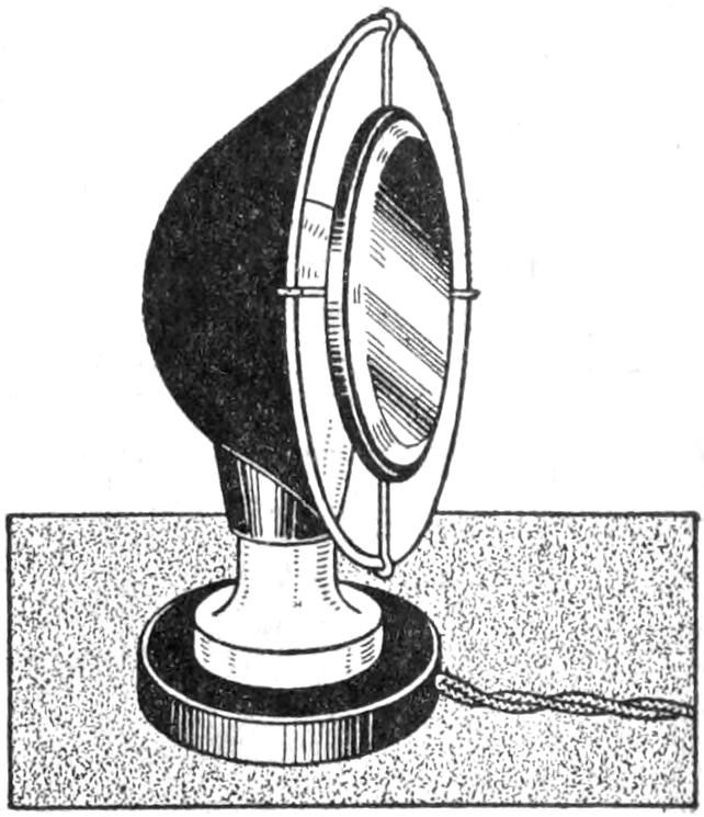
A small mirror combined with a shaded electric lamp affords a nearly perfect shaving lamp, and facial toilet mirror. The mirror should be 1 in. smaller all around than the reflector. By soldering two lengths of stiff wire to the back of the mirror frame, it can be clamped to the reflector, as shown. The indirect light from the reflector illuminates the face without shadows or glare, adding to the comfort of shaving. The mirror can be removed, and the lamp used for other purposes.—Thomas W. Benson, Philadelphia, Pa.
[461]
The language used in this text is that of the sourcce document; changes to the text are listed below.
Depending on the hard- and software and their settings used to read this text not all elements may display as intended; many images may be enlarged by opening them in a new window or tab.
Page 32, ... an angle of about 2°: possibly an error for ... an angle of about 20° (which is the angle in the illustration).
Page 113, illustration top right (Food Bags): Fut and Ergswurst may be errors for Fat and Erbswurst (pea sausage).
Page 262, ... in Fig. 9, illustrating an article on “Taborets and Small Tables for the Summer Veranda,” page 155, July, 1916 ...: an article with this title (presumably the one referred to) is present in this book on page 269.
Changes made
Illustrations have been moved out of text paragraphs.
Minor obvious typographical errors have been corrected silently.
Text in a dotted box has been transcribed from the accompanying illustration, and does not appear as part of the text in the source document.
Some entries in the table of contents have been corrected to conform to the spelling used in the text.
In some of the illustrations feet or misprinted inch symbols (′) have been changed to inch symbols (″) when necessary.
On several pages the first letter of the main article has been replaced with a large capital, as in similar articles in the book.
Page 29: Fig 7 has been rotated 90°.
Page 89: ... directly from the canoe, or part, to be fitted, whenever convenient ... changed to ... directly from the canoe, or part to be fitted, whenever convenient ....
Page 94: illustration Ice Creeper turned upside-down.
Page 213: ... a wear and noise-proof bearing ... changed to ... a wear- and noise-proof bearing ....