The Project Gutenberg EBook of Photographs of Nebulæ and Clusters, by
James Edward Keeler

This eBook is for the use of anyone anywhere at no cost and with
almost no restrictions whatsoever.  You may copy it, give it away or
re-use it under the terms of the Project Gutenberg License included
with this eBook or online at www.gutenberg.org


Title: Photographs of Nebulæ and Clusters
       Made with the Crossley Reflector

Author: James Edward Keeler

Release Date: June 19, 2011 [EBook #36470]

Language: English

Character set encoding: ISO-8859-1

*** START OF THIS PROJECT GUTENBERG EBOOK PHOTOGRAPHS OF NEBULÆ AND CLUSTERS ***


Produced by Bryan Ness and the Online Distributed
Proofreading Team at http://www.pgdp.net (This file was
produced from images generously made available by The
Internet Archive/American Libraries.)
NOTE.
In the original negatives of subjects 10 and 12, there are faint dark rings immediately surrounding some of the stars in the denser parts of the nebulosity. This effect has no doubt been accentuated in the subsequent photographic processes. On the plates of these two subjects in the completed volume, these rings are very distinct and give rise to a suspicion that the effect has been enhanced by the engraver. A critical examination of the prints seems to confirm this view. In the original proofs these rings were inconspicuous and were not noticed. The processes of steel-facing and printing appear to have increased the effect markedly, as it is much stronger on the sheets printed for the edition than in any of the early proofs.
Inasmuch as these effects were not and could not be discovered until the sheets were assembled in Sacramento for binding, it has not been thought desirable to delay the issue of the volume for several weeks additional in order to have new plates and new prints of these subjects made by the distant engraver.
Lick Observatory,
Mount Hamilton,
November, 1908.
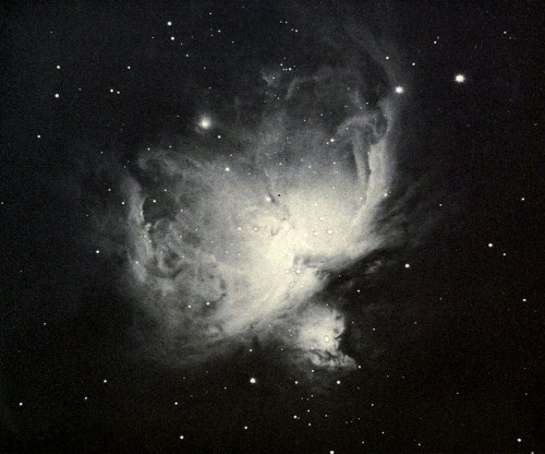
Plate 10
The Great Nebula in Orion
UNIVERSITY OF CALIFORNIA PUBLICATIONS
PUBLICATIONS
OF THE
LICK OBSERVATORY
PRINTED BY AUTHORITY OF THE REGENTS OF THE UNIVERSITY
VOLUME VIII
| SACRAMENTO | ||
| W. W. Shannon | Superintendent of State Printing | |
| 1908 | ||
As a Tribute To the Memory of
JAMES EDWARD KEELER
and in recognition of his great worth as a man and as an astronomer, the plates for this volume have been provided by
| MR. WILLIAM ALVORD, | MR. F. M. SMITH, | |
| MR. ROBERT BRUCE, | MISS JENNIE SMITH, | |
| MR. WILLIAM H. CROCKER, | MISS MATILDA H. SMITH, | |
| MRS. WILLIAM H. CROCKER, | MR. BENJAMIN THAW, | |
| MR. E. J. DE SABLA, | MRS. WILLIAM THAW, | |
| MR. J. A. DONOHOE, | MR. ROBERT J. TOBIN, | |
| MRS. PHŒBE A. HEARST, | THE UNIVERSITY OF CALIFORNIA, | |
| MR. JOHN B. JACKSON, | THE STATE OF CALIFORNIA. | |
| MR. E. J. MOLERA, |
ORGANIZATION OF THE LICK OBSERVATORY.
| Hon. Charles W. Slack, | Hon. Warren R. Porter, | |
| Hon. William H. Crocker, | Rev. Peter C. Yorke, | |
| Committee of the Regents for the Lick Observatory. | ||
| Benjamin Ide Wheeler, | President of the University. | |
| W. W. Campbell, | Director and Astronomer. | |
| R. H. Tucker,* | Astronomer. | |
| C. D. Perrine, | Astronomer. | |
| H. D. Curtis, | Mills Acting Astronomer. | |
| R. G. Aitken, | Astronomer. | |
| W. H. Wright, | Astronomer. | |
| J. H. Moore, | Assistant Astronomer. | |
| Sebastian Albrecht, | Assistant Astronomer. | |
| Miss A. M. Hobe, | Carnegie Assistant. | |
| G. F. Paddock, | Mills Assistant. | |
| Miss L. B. Allen, | Carnegie Assistant. | |
| E. A. Fath, | Fellow. | |
| J. C. Duncan, | Fellow. | |
| Miss A. E. Glancy, | Fellow. | |
| Miss M. E. French,* | Secretary. | |
| Miss A. J. Van Coover, | Secretary. | |
| * Absent on leave. | ||
PHOTOGRAPHS OF NEBULÆ AND CLUSTERS,
MADE WITH
THE CROSSLEY REFLECTOR,
BY
JAMES EDWARD KEELER,
DIRECTOR OF THE LICK OBSERVATORY.
1898-1900.
When Professor Keeler entered upon the duties of Director of the Lick Observatory, on June 1, 1898, he planned to devote his observing time for several years to photographing the brighter nebulæ and star clusters, with the Crossley reflector. The story of his wonderful success with this difficult instrument is familiar to all readers of astronomical literature: this form of telescope was in effect born again; and his contributions to our knowledge of the nebulæ were epoch-making.
Professor Keeler’s observing programme included one hundred and four subjects. At the time of his lamented death, on August 12, 1900, satisfactory negatives of two-thirds of the selected objects had been secured. The unphotographed objects were mainly those which come into observing position in the unfavorable winter and spring months. The completion of the programme was entrusted to Assistant Astronomer Perrine. The observers were assisted chiefly by Mr. H. K. Palmer, and in smaller degree by Messrs. Joel Stebbins, C. G. Dall, R. H. Curtiss and Sebastian Albrecht.
Professor Keeler’s photographs enabled him to make two discoveries of prime importance, not to mention several that are scarcely secondary to them.
1st.—“Many thousands of unrecorded nebulæ exist in the sky. A conservative estimate places the number within reach of the Crossley reflector at about 120,000. The number of nebulæ in our catalogues is but a small fraction of this.” [The number already discovered and catalogued did not exceed 13,000. Later observations with the Crossley reflector, with longer exposure-times and more sensitive plates, render it probable that the number of nebulæ discoverable with this powerful instrument is of the order of half a million.]
2d.—“Most of these nebulæ have a spiral structure.”
The photographs of the one hundred and four subjects contain the images of 744 nebulæ not previously observed. A catalogue of these is published in the present volume. Their positions, which are thought to be accurate within 1″, were determined by Messrs. Palmer, Curtiss, and Albrecht.
The main purpose of this volume is to reproduce and make available for study, the larger and more interesting nebulæ and clusters on the programme, sixty-eight in number. The thirty-six subjects not reproduced are for the most[Pg 8] part small or apparently not of special interest. The difficulties attending the reproduction of astronomical photographs by mechanical processes are well-known to all who have made the attempt. It seems necessary to recognize, at least at present, that delicate details of structure will be lost, and that contrasts between very bright and very faint regions will be changed, especially if a good sky background is preserved; in other words, that the best obtainable reproductions fall far short of doing justice to the original photographs. Technical studies should be based upon the original negatives or upon copies on glass.
After considerable experimental work, involving several methods and several firms, the making of the heliogravure plates and the hand-press prints was entrusted to The Photogravure and Color Company of New York City. To this firm’s continued interest and willingness to act on constructive criticism is due much of the excellence of the results.
The expensive reproductions could hardly have been undertaken without the generous assistance of the donors mentioned on a preceding page.
Professor Keeler’s description of the Crossley reflector, of his methods of observing, and of the chief results obtained, was written only a short time before his death. It is here republished. Other results of his work are described in the several papers to which the footnotes refer.
| The Orion Nebula, | Frontispiece | ||
| The Crossley Reflector of the Lick Observatory, | Page | 11 | |
| List of Nebulæ and Clusters Photographed, | " | 30 | |
| Catalogue of New Nebulæ Discovered on the Negatives, | " | 31 | |
| Positions of Known Nebulæ Determined from the Crossley Negatives, | " | 42 | |
| List of Illustrations, | " | 45 | |
| Illustrations, | following | " | 46 |
By James E. Keeler.
The Crossley reflector, at present the largest instrument of its class in America, was made in 1879 by Dr. A. A. Common, of London, in order to carry out, and test by practical observation, certain ideas of his respecting the design of large reflecting telescopes. For the construction of the instrument embodying these ideas, and for some fine astronomical photographs obtained with it, Dr. Common was awarded the gold medal of the Royal Astronomical Society in 1884.
In 1885, Dr. Common, wishing to make a larger telescope on a somewhat similar plan, sold the instrument to Edward Crossley, Esq., F. R. A. S., of Halifax, England. Mr. Crossley provided the telescope with a dome of the usual form, in place of the sliding roof used by its former owner, and made observations with it for some years; but the climate of Halifax not being suitable for the best use of such a telescope, he consented, at the request of Dr. Holden, then Director of the Lick Observatory, to present it to this institution. The funds for transporting the telescope and dome to California, and setting them up on Mount Hamilton, were subscribed by friends of the Lick Observatory, for the most part citizens of California. The work was completed, and the telescope housed in a suitable observatory building, in 1895.[2]
On taking charge of the Lick Observatory in 1898, I decided to devote my own observing time to the Crossley reflector, although the whole of my previous experience had been with refracting telescopes. I was more particularly desirous of testing the reflector with my own hands, because such preliminary trials of it as had been made had given rise to somewhat conflicting opinions as to its merits.[3] The result of my experience is given in the following article, which is written chiefly with reference to American readers. If I have taken occasion to point out what I regard as defects in the design or construction of the instrument, I have done so, not from any desire to look a gift horse in the mouth, but in the interest of future improvement, and to make intelligible the circumstances under which the work of the reflector is now being done and will be done hereafter. The most important improvements which have suggested themselves have indeed already[Pg 12] been made by Dr. Common himself, in constructing his five-foot telescope. The three-foot reflector is, in spite of numerous idiosyncracies which make its management very different from the comparatively simple manipulation of a refractor, by far the most effective instrument in the Observatory for certain classes of astronomical work. Certainly no one has more reason than I to appreciate the great value of Mr. Crossley’s generous gift.
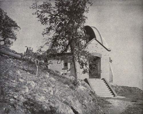
DOME OF THE CROSSLEY REFLECTOR.
The Crossley dome is about 350 yards from the main Observatory, at the end of a long rocky spur which extends from the Observatory summit toward the south, and on which are two of the houses occupied by members of the Observatory staff. It is below the level of the lowest reservoir, “Huyghens,” which receives the discharge from the hydraulic machinery of the 36-inch refractor, and therefore the water engine furnished by Mr. Crossley for turning the dome can not be used, unless a new water system—overflow reservoir, pump and windmill—is provided. In this respect a better site would have been a point on the south slope of “Kepler,”—the middle peak of Mount Hamilton—just above the Huyghens reservoir. No addition to the present water system would then have been needed. The[Pg 13] slope of the mountain at this place might cut off the view of the north horizon, but since the telescope can not be turned below the pole, this would be a matter of no consequence. Water-power for the dome is not, however, really necessary.
The cylindrical walls of the dome, 36¼ feet inside diameter, are double, and provided with ventilators. Opening into the dome, on the left of the entrance, are three small rooms, one of which has been fitted up as a photographic dark room, and another, containing a sidereal clock and a telephone, which communicates with the main Observatory, as a study, while the third is used for tools and storage. There is also a small room for the water engine, in case it should be used. The dome is at present supplied with water from only the middle reservoir, Kepler, which is reserved for domestic purposes and is not allowed to pass through the machinery.
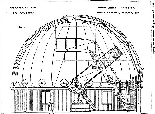
The dome itself, 38 feet 9 inches in diameter, is made of sheet-iron plates riveted to iron girders. It also carries the wooden gallery, ladders, and observing platform, which are suspended from it by iron rods. The apparatus for turning the dome consists of a cast-iron circular rack bolted to the lower side of the sole-plate, and a set of gears terminating in a sprocket-wheel, from which hangs an endless rope. As the dome does not turn easily, it has been necessary to multiply the gearing of the mechanism so that one arm’s-length pull on the rope moves the dome only about one inch. In some positions of the telescope the dome can not be moved more than six or eight inches at a time without danger of striking the tube, and this slowness of motion is then not disadvantageous. It is only when the dome has to be moved through a considerable angle, as in turning to a fresh object, or in photographing some object which passes nearly through the zenith, that the need for a mechanical means of rotation is felt.
The observing slit, 6 feet wide, extends considerably beyond the zenith. It is closed by a double shutter, which is operated by an endless rope. The upper part, within the dome, is also closed by a hood, or shield, which serves to protect the telescope from any water that may find its way through the shutter, and which is rolled back to the north when observations are made near the zenith. I have recently fitted the lower half of the slit with a wind-screen, which has proved to be a most useful addition. It is made of tarpaulin, attached to slats which slide between the two main girders, and is raised or lowered by halliards, which belay to cleats on the north rail of the gallery. A more detailed description of the dome has been given in an article by Mr. Crossley,[4] from which the reduced figure in Fig. 1[5] has been taken.
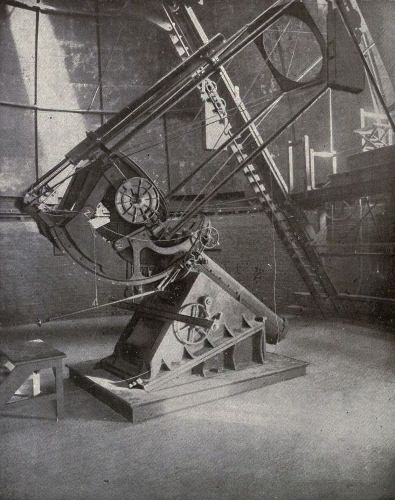
The mounting of the three-foot reflector has been very completely described and illustrated by Dr. Common,[6] so that only a very general description need be[Pg 14] given here. The most important feature of the mounting is that the telescope tube, instead of being on one side of the polar axis, as in the usual construction, is central, so that the axis of the mirror and the polar axis are in the same line when the telescope is directed to the pole. The declination axis is short, and is supported by a massive goose-neck bolted to the upper end of the polar axis. The mirror is placed just above the declination axis. Its weight, and the weight of the whole tube and eye-end, are counterpoised by slabs of lead, placed in two iron boxes, between which the goose-neck of the polar axis passes. The great advantage of this arrangement, and the controlling principle of the design, is that the telescope is perfectly free to pass the meridian at all zenith distances. No reversal of the instrument is needed, or is indeed possible.
THE CROSSLEY REFLECTOR.
For long-exposure photography, the advantage above referred to is obvious, but it is attended by certain disadvantages. One of these is that a very much larger dome is required than for the usual form of mounting. Another is the great amount of dead weight which the axes must carry; for the mirror, instead of helping to counterpoise the upper end of the tube, must itself be counterpoised. When anything is attached to the eye-end (and in astrophysical work one is always attaching things to the eye-end of a telescope), from ten to twenty times as much weight must be placed in the counterpoise boxes below the declination axis. Where room is to be found for the weights required to counterpoise the Bruce spectrograph, is a problem which I have not yet succeeded in solving.
In his five-foot reflector, Dr. Common has caused the telescope tube to swing between two large ears, which project from the upper end of the boiler-like polar axis, the pivots constituting the declination axis being near, but above, the lower end of the tube. The mirror, therefore, helps to counterpoise the upper end of the[Pg 15] tube. This I regard as a distinct improvement. The danger of large masses of metal near the mirror injuring the definition is, in my opinion, imaginary; at least there is no such danger on Mount Hamilton, where the temperature variations are unusually small. Experience with the Crossley reflector, as well as with the other instruments of the Lick Observatory, shows that the definition depends almost entirely on external conditions.
My first trials of the reflector, as first mounted at the Lick Observatory, showed that the center of motion was inconveniently high. Among other difficulties arising from this circumstance, the spectroscope projected beyond the top of the dome, so that it had to be removed before the shutter could be closed. In July, 1898, the pier was therefore cut down two feet. This brought the eye-end down nearly to the level of the gallery rail, where it was at a convenient height for the observer when sitting on a camp-stool, and it made all parts of the mounting more accessible. Toward the north and south, the range of the telescope, being limited in these directions by the construction of the mounting, was not affected by the change, but the telescope can not now be used at such low altitudes as formerly, near the east and west points of the horizon. The only occasion likely to call for the use of the reflector in these positions is the appearance of a large comet near the Sun, and, after some consideration, I decided to sacrifice these chances for the sake of increasing the general usefulness of the instrument. Except in rare cases, all observations are made within three hours of the meridian.
To adapt the mounting to the latitude of Mount Hamilton, a wedge-shaped casting, shown in the illustration, had been provided, but through some error, arising probably from the fact that the telescope had been used in two different latitudes in England, the angle of the casting was too great. When the pier was cut down its upper surface was therefore sloped toward the south, in order to compensate the error in the casting. Plate VII shows the instrument very nearly as it is at the present time.
The polar axis of the Crossley reflector is a long, hollow cylinder, separated by a space of about one-eighth of an inch from its concentric casing. The idea was to fill this space with mercury, and float the greater part of the thrust of the axis, the function of a small steel pin at the lower end being merely to steady the axis. But this mercury flotation, as applied to the Crossley telescope, is a delusion, as I think Mr. Crossley had already found. The mercury, it is true, relieves the thrust to some extent, but it greatly increases the already enormous side pressure on the steel pin at the bottom, thus creating a much greater evil than the one it is intended to remedy. The workmen who set up the mounting inform me that the small bearing at the lower end of the polar axis is badly worn, as I should expect it to be. Instead of putting mercury into the space intended for it, I have therefore poured in a pint or so of oil, to keep the lower bearing lubricated. For the reasons indicated above, the force required to move the telescope in right[Pg 16] ascension is perhaps five times greater than it should be. The lower end of the polar axis ought to be fitted with ball bearings to take the thrust, and with a pair of friction wheels on top; but it would be difficult to make these changes now. It should be observed that the disadvantages of the mercury flotation are considerably greater at Mount Hamilton than at the latitude for which the telescope was designed.
THE CROSSLEY REFLECTOR.
As already stated above, the range of the telescope is limited on the south by the construction of the mounting. The greatest southern declination which can be observed is 25°. In England this would doubtless mark the limit set by atmospheric conditions, but at Mount Hamilton it would be easy to photograph objects 15° farther south, if the telescope could be pointed to them.
[Pg 17]The original driving-clock having proved to be inefficient, at least without an electric control, a new and powerful driving-clock was made by the Observatory instrument maker, from designs by Professor Hussey. In its general plan it is like that of the 36-inch refractor. The winding apparatus, contained in the large casting of the original mounting, has no maintaining power, and can not easily be fitted with one. The clock could in no case be wound during a photographic exposure, on account of the tremors attending the operation, but it would be somewhat more convenient to have the stars remain on the plate during the winding. With a little practice, however, one can wind the clock without actually stopping it, though the object must afterwards be brought back to its place by means of the slow motion in right ascension.
Two finders have recently been fitted to the Crossley reflector. One has an object-glass of four inches aperture and eight feet six inches focal length, with a field of about 1° 2′, which is very nearly the photographic field of the main telescope. Its standards are bolted to one of the corner tubes of the reflector. The other finder has a three-inch objective and a large field. It had not been mounted when the photograph for the plate was made.
When a telescope is used for photographing objects near the pole, with long exposures, the polar axis must be quite accurately adjusted, for otherwise the centers of motion of the stars and of the telescope will not agree, and the star images will be distorted. It is true that with a double-slide plate-holder, like the one used with the Crossley reflector, one star—namely, the guiding star—is forced to remain in a fixed position with respect to the plate; but the differential motion of the other stars causes them to describe short arcs, or trails, around this star as a center. A considerable part of the spring of 1899 was spent in efforts to perfect the adjustment of the polar axis, an operation which, on account of the peculiar form of the mounting, offers unusual difficulties.
In the first plan which was tried, the reflector was used as a transit instrument. The inclination of the declination axis was determined with a hanging level which had been provided by Mr. Crossley, the hour circle and polar axis being very firmly clamped. The clock correction being known from the records kept at the Observatory, the collimation and azimuth constants were found by the usual formulæ. This method failed to give satisfactory results, and it was found later that the declination and polar axis were not exactly at right angles.
There is only one part of the sky on which the telescope can be reversed; namely, the pole. A method which promised well, and on which some time was spent, consists in photographing the pole (the declination axis being horizontal) by allowing the stars near it to trail for ten or fifteen minutes, then turning the polar axis 180° and photographing the pole again on the same plate. Half the distance between the images gives the error of the polar axis, which, if the plate is properly oriented, is easily resolved into horizontal and vertical components;[Pg 18] while the distance of each image from the center of the plate is this error increased or diminished by twice the deviation of the telescope axis. In this case the vertical component depends upon the reading of the declination circle, and the horizontal component gives the error of collimation. This method failed, however, to give consistent results, mainly on account of instability of the mirror, and was abandoned.
The use of the large mirror for purposes of adjustment was finally given up, and the axis was adjusted by observations of Polaris with the long finder, in the usual manner. In order to reach the star at lower culmination the finder tube had to be thrown out of parallelism with the main telescope.
The base-plate having no definite center of rotation in azimuth, and the wedges and crowbars used for moving it being uncertain in their action, a watch telescope, provided with a micrometer eyepiece, was firmly secured to the mounting throughout these operations, in such manner that a mark on the southern horizon could be observed through one of the windows of the dome. The errors of the polar axis were finally reduced to within the limits of error of observation.
The movable hour circle and driving wheel of the Crossley reflector has two sets of graduations. The driving screw having been thrown out of gear, the circle is turned until the outer vernier indicates the sidereal time, whereupon the driving screw is thrown into gear again. The inner vernier is then set to the right ascension of the object which it is desired to observe. As an inconsistency, of minor importance, in the design of the mounting, I may note that the slow motion in right ascension changes the reading of the outer vernier instead of that of the inner one. In practice, however, no inconvenience is caused by this construction.
In the early experiments and photographic work with the Crossley telescope, irregularities in driving were a source of great annoyance. Dr. Roberts, in laying down the conditions which should be fulfilled by a good photographic telescope, says that a star should remain bisected by a thread in the eyepiece for two minutes at a time. The Crossley telescope was so far from fulfilling this condition that a star would not keep its place for two consecutive seconds; and the greatest alertness on the part of the observer did not suffice to ensure round star images on a photographic plate. It was obvious that the fault did not lie with the driving clock; in fact, many of the sudden jumps in right ascension, if explained in this way, would have required the clock to run backward; nevertheless the clock was tested by causing its revolutions to be recorded on a chronograph at the main Observatory, together with the beats of one of the standard clocks. For this purpose a break-circuit attachment was made by Mr. Palmer. The errors of the clock were in this way found to be quite small.
The principal source of the irregularities was found in the concealed upper differential wheel of the Grubb slow motion. This wheel turned with uncertain[Pg 19] friction, sometimes rotating on its axis, and sometimes remaining at rest. After it was checked the driving was much better, and was still farther improved by repairing some defective parts of the train. Small irregularities still remain. They seem to be partly due to inaccuracies in the cutting of the gears, or of the teeth of the large driving wheel, and partly to the springing of the various parts, due to the very considerable friction of the polar axis in its bearings. The remaining irregularities are so small, however, that they are easily corrected by the screws of the sliding plate-holder, and with reasonable attention on the part of the observer, round star images are obtained with exposures of four hours’ duration.
The large mirror, the most important part of the telescope, has an aperture of three feet, and a focal length of 17 feet 6.1 inches. It was made by Mr. Calver. Its figure is excellent. On cutting off the cone of rays from a star, by a knife-edge at the focus, according to the method of Foucault, the illumination of the mirror is very uniform, while the star disks as seen in an ordinary eyepiece are small and almost perfectly round. They are not, I think, quite so good as the images seen with a large refractor; still, they are very good indeed, as the following observations of double stars, made recently for this purpose, will show.
Several close double stars were examined on the night of April 17, 1900, with a power of 620. The seeing was four on a scale of five. The magnitudes and distances of the components, as given in the table, are from recent observations by Professor Hussey with the 36-inch refractor.
| Star. | Mag. | d. | Result of Obs. | |||
| ΟΣ 208 (φ Urs. Maj.) | 5.0, 5.5 | 0″.35 | Not resolved; too bright. | |||
| ΟΣ 249, AB | 7.2, 8.0 | 0 .54 | Easily resolved. | |||
| ΟΣ 250 | 7.7, 8.0 | 0 .44 | Resolved. | |||
| ΟΣ 267 | 8.0, 8.2 | 0 .30 | Just resolved at best moments. |
Although the theoretical limit of resolution for a three-foot aperture is not reached in these observations, I do not think the mirror can do any better.
The small mirror, or flat, at the upper end of the tube, is circular, the diameter being nine inches. Its projection on the plane of the photographic plate is therefore elliptical; but the projection of the mirror and its cell on the plane of the great mirror is very nearly circular.
The small mirror, acting as a central stop, has the effect of diminishing the size of the central disk of the diffraction pattern, at the expense of an increase in the brightness of the system of rings. To this effect may be due, in part, the inferiority of the reflector for resolving bright doubles, as compared with a refractor of the same aperture. For photographic purposes, it is evident that the mirror is practically perfect.
The upper end of the tube can be rotated, carrying with it the flat and the eye-end. Whenever the position is changed, the mirrors have to be re-collimated. In practice it is seldom necessary to touch the adjusting screws of the mirrors[Pg 20] themselves. The adjustment is effected by means of clamping and butting screws on the eye-end, and a change of the line of collimation, with respect to the finders and the circles, is avoided. The operation is generally referred to, however, as an adjustment of the mirrors.
For adjusting the mirrors there are two collimators. One of these is of the form devised by Mr. Crossley.[7] It is very convenient in use, and is sufficiently accurate for the adjustment of the eye-end when the telescope is used for photographic purposes, inasmuch as the exact place where the axis of the large mirror cuts the photographic plate is not then a matter of great importance, so long as it is near the center. Moreover, as stated farther below, the direction of the axis changes during a long exposure. The other collimator is of a form originally due, I think, to Dr. Johnstone Stoney. It consists of a small telescope, which fits the draw-tube at the eye-end. In the focus of the eyepiece are, instead of cross-wires, two adjustable terminals, between which an electric spark can be passed, generated by a small induction machine, like a replenisher, held in the observer’s hand. The terminals are at such a distance inside the principal focus of the objective, that the light from the spark, after reflection from the flat, appears to proceed from the center of curvature of the large mirror. The rays are therefore reflected back normally, and form an image of the spark which, when the mirrors are in perfect adjustment, coincides with the spark itself. The precision of this method is very great. It is in fact out of proportion to the degree of refinement attained in other adjustments of the reflector, for a slight pressure of the hand on the draw-tube, or movement of the telescope to a different altitude, instantly destroys the perfection of the adjustment. I have provided these collimators with an adapter which fits the photographic apparatus, so that one can adjust the mirrors without having to remove this apparatus and substitute for it the ordinary eye-end carrying the eyepieces.
For visual observation the Crossley telescope is provided with seven eyepieces, with powers ranging from 620 downward. The lowest power is only 60, and consequently utilizes only 12 inches of the mirror, 9 of which are covered by the central flat. It is therefore of little value, except for finding purposes. The next lowest power utilizes 28 inches of the mirror. The other eyepieces call for no remark.
But, while the Crossley reflector would doubtless be serviceable for various kinds of visual observations, its photographic applications are regarded as having the most importance, and have been chiefly considered in deciding upon the different changes and improvements which have been made.
The interior of the dome is lighted at night by a large lamp, which is enclosed in a suitable box or lantern, fitted with panes of red glass, and mounted on a portable stand. In order to diffuse the light in the lower part of the dome, where most[Pg 21] of the assistant’s work is done, the walls are painted bright red; while to prevent reflected light from reaching the photographic plate, the inner surface of the dome itself, the mounting, and the ladders and gallery are painted dead black. The observer is therefore in comparative darkness, and not the slightest fogging of the plate, from the red light below, is produced during a four-hours’ exposure. On the few occasions when orthochromatic plates are used the lamp need not be lighted.
Experiments have shown that the fogging of the photographic plate, during a long exposure, is entirely due to diffuse light from the sky, and is therefore unavoidable. For this reason the cloth curtains which lace to the corners of the telescope tube, enclosing it and shutting out light from the lower part of the dome, have not been used, since their only effect would be to catch the wind and cause vibrations of the telescope. They would probably have little effect on the definition, and at any rate could not be expected to improve it.
For photographing stars and nebulæ the Crossley reflector is provided with a double-slide plate-holder, of the form invented by Dr. Common.[8] This apparatus, which had suffered considerably in transportation, and from general wear and tear, was thoroughly overhauled by the Observatory instrument-maker. The plates were straightened and the slides refitted. A spring was introduced to oppose the right ascension screw and take up the lost motion—the most annoying defect that such a piece of apparatus can have—and various other improvements were made, as the necessity for them became apparent. They are described in detail farther below.
The present appearance of the eye-end is shown in the illustration. The plate-holder is there shown, however, on one side of the tube, and its longer side is parallel to the axis of the telescope. This is not a good position for the eye-end, except for short exposures. In practice, the eye-end is always placed on the north or south side of the tube, according as the object photographed is north or south of the zenith. The right ascension slide is then always at right angles to the telescope axis, and the eye-end can not get into an inaccessible position during a long exposure.
As the original wooden plate-holders were warped, and could not be depended upon to remain in the same position for several hours at a time, they were replaced by new ones of metal, and clamping screws were added, to hold them firmly in place. The heads of these screws are shown in the plate, between the springs which press the plate-holder against its bed.
To illuminate the cross-wires of the guiding eyepiece, a small electric lamp is used, the current for which is brought down from the storage battery at the main[Pg 22] Observatory. The coarse wires have been replaced by spider’s webs,[9] and reflectors have been introduced, to illuminate the declination thread. A collimating lens, placed at its principal focal distance from the incandescent filament of the lamp, makes the illumination of the wires nearly independent of their position on the slide, and a piece of red glass, close to the lens, effectually removes all danger of fogging the plate. The light is varied to suit the requirements of observation by rotating the reflector which throws the light in the direction of the eyepiece.
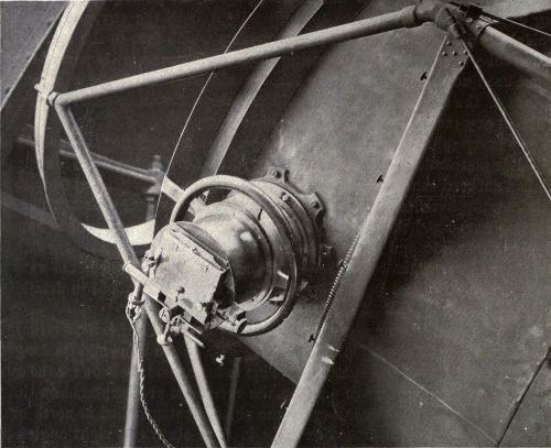
DOUBLE-SLIDE PLATE-HOLDER OF THE CROSSLEY REFLECTOR.
In long exposures it is important for the observer to know at any moment the position of the plate with reference to its central or zero position. For this purpose scales with indexes are attached to both slides; but as they can not be seen in the dark, and, even if illuminated with red light, could not be read without removing the eye from the guiding eyepiece, I have added two short pins, one of[Pg 23] which is attached to the lower side of the right ascension slide, and the other to its guide, so that the points coincide when the scale reads zero. These pins can be felt by the fingers, and with a little practice the observer can tell very closely how far the plate is from its central position. It would not be a very difficult matter to improve on this contrivance, say by placing an illuminated scale, capable of independent adjustment, in the field of the eyepiece, but the pins answer every purpose. The declination slide is changed so little that no means for indicating its position are necessary.
In this apparatus, as originally constructed, the cross-wires of the guiding eyepiece were exactly in the plane of the photographic plate. The earlier observations made with the Crossley reflector on Mount Hamilton showed that this is not the best position of the cross-wires. The image of a star in the guiding eyepiece, which, when in the middle of its slide, is nearly three inches from the axis of the mirror, is not round, and its shape varies as the eyepiece is pushed in or drawn out. In the plane of the photographic plate (assumed to be accurately in focus), it is a crescent, with the convex side directed toward the center of the plate. This form of image is not suitable for accurate guiding. Outside this position the image changes to an arrow-head, the point of which is directed toward the axis, and this image can be very accurately bisected by the right ascension thread. As the construction of the apparatus did not allow the plane of the cross-wires to be changed, the wooden bed of the plate-holder was cut down, so as to bring the wires and the plate into the proper relative positions.
After some further experience with the instrument, still another change was made in this adjustment. It was found that the focus often changed very perceptibly during a long exposure, and while the arrow-head image above described was suitable for guiding purposes, its form was not greatly affected by changes of focus. Between the crescent and the arrow-head images there is a transition form, in which two well-defined caustic curves in the aberration pattern intersect at an acute angle. The intersection of these caustics offers an excellent mark for the cross-wires, and is at the same time very sensitive to changes of focus, which cause it to travel up or down in the general pattern. The bed of the plate-holder was therefore raised, by facing it with a brass plate of the proper thickness.
Why the focus of the telescope should change during a long exposure is not quite clear. The change is much too great to be accounted for by expansion and contraction of the rods forming the tube, following changes of temperature, while a simple geometrical construction shows that a drooping of the upper end of the tube, increasing the distance of the plate from the (unreflected) axis of the mirror, can not displace the focus in a direction normal to the plate, if it is assumed that the field is flat. The observed effect is probably due to the fact that the focal surface is not flat, but curved. During a long exposure, the observer keeps the guiding star, and therefore, very approximately, all other stars, in the same [Pg 24]positions relatively to the plate; but he has no control over the position of the axis of the mirror, which, by changes of flexure, wanders irregularly over the field. The position of maximum curvature, therefore, also varies, and with it the focus of the guiding star relatively to the cross-wires, where the focal surface is considerably inclined to the field of view. It is certain that the focus does change considerably, whatever the cause may be, and that the best photographic star images are obtained by keeping the focus of the guiding star unchanged during the exposures. This is done by turning the focusing screw of the eye-end.
In making the photographs of nebulæ for which the Crossley telescope is at present regularly employed, it was at first our practice to adjust the driving-clock as accurately as possible to a sidereal rate, and then, when the star had drifted too far from its original position, on account of changes of rate or of flexure, to bring it back by the right-ascension slow motion, the observer either closing the slide of the plate-holder or following the motion of the star as best he could with the right-ascension screw. Lately a more satisfactory method, suggested by Mr. Palmer, has been employed. The slow motion in right ascension is of Grubb’s form,[10] and the telescope has two slightly different rates, according to whether the loose wheel is stopped or allowed to turn freely. The driving-clock is adjusted so that one of these rates is too fast, the other too slow. At the beginning of an exposure the wheel is, say, unclamped, and the guiding star begins to drift very slowly toward the left, the observer following it with the screw of the plate-holder. When it has drifted far enough, as indicated by the pins mentioned farther above, the wheel is clamped. The star then reverses its motion and begins to drift toward the right; and so on throughout the exposure. The advantages of this method over the one previously employed are, that the star never has to be moved by the slow motion of the telescope, and that its general drift is in a known direction, so that its movements can be anticipated by the observer. In this way photographs are obtained, with four hours’ exposure, on which the smallest star disks are almost perfectly round near the center of the plate, and from 2″ to 3″ in diameter.
The star images are practically round over a field at least 1 inch or 16′ in diameter. Farther from the center they become parabolic, but they are quite good over the entire plate, 3¼ by 4¼ inches.
From these statements it will be seen that small irregularities in driving no longer present any difficulties. But certain irregular motions of the image still take place occasionally, and so far it has not been possible entirely to prevent their occurrence.
It was found that the declination clamp (the long slow-motion handle attached to which is shown in the illustration) was not sufficiently powerful to hold the telescope firmly during a long exposure. A screw clamp was therefore added, which[Pg 25] forces the toothed-declination sector strongly against an iron block just behind it, thus restoring, I think, the original arrangement of the declination clamp as designed by Dr. Common. This clamp holds the tube very firmly.
The irregularities to which I have referred consist in sudden and unexpected jumps of the image, which always occur some time after the telescope has passed the meridian. These jumps are sometimes quite large—as much as one-sixteenth of an inch or 1. They are due to two causes: flexure of the tube, and sliding of the mirror on its bed. When the jump is due to sudden changes of flexure, the image moves very quickly, and vibrates before it comes to rest in its new position, and at the same time there is often heard a slight ringing sound from the tension rods of the tube. There seems to be no remedy for the sudden motions of this class. The tension rods are set up as tightly as possible without endangering the threads at their ends or buckling the large corner tubes. A round telescope tube, made of spirally-wound steel ribbon riveted at the crossings, would probably be better than the square tube now in use.
Jumps due to shifting of the mirror are characterized by a gentle, gliding motion. They can be remedied, in part, at least, by tightening the copper bands which pass around the circumference of the mirror within its cell. This will be done the next time the mirror is resilvered.
All that the observer can do when a jump occurs is to bring back the image as quickly as possible to the intersection of the cross-wires. If all the stars on the plate are faint, no effect will be produced on the photograph; but stars of the eighth magnitude or brighter will leave short trails. The nebula, if there is one on the plate, will, of course, be unaffected.
Before beginning an exposure the focus is adjusted by means of a high-power positive eyepiece. An old negative, from which the film has been partially scraped, is placed in one of the plate-holders, and the film is brought into the common focus of the eyepiece and the great mirror. The appearance of the guiding star, which varies somewhat with the position of the guiding eyepiece on its slide, is then carefully noted, and is kept constant during the exposure by turning, when necessary, the focusing screw of the eye-end. For preliminary adjustments a ground-glass screen is often convenient. On it all the DM. stars, and even considerably fainter ones, as well as the nebulæ of Herschel’s Class I, are easily visible without a lens.
Plates are backed, not more than a day or two before use, with Carbutt’s “Columbian backing,” which is an excellent preparation for this purpose. During the exposure the observer and assistant exchange places every half hour, thereby greatly relieving the tediousness of the work, though two exposures of four hours each, in one night, have proved to be too fatiguing for general practice. At the end of the first two hours it is necessary to close the slide and wind the clock.
[Pg 26]The brightness of the guiding star is a matter of some importance. If the star is too bright, its glare is annoying; if it is too faint, the effort to see it strains the eye, and changes of focus are not easily recognized. A star of the ninth magnitude is about right. In most cases a suitable star can be found without difficulty.
In such an apparatus as that described above, the amount by which the plate may be allowed to depart from its zero position is subject to a limitation which has not, I think, been pointed out, although it is sufficiently obvious when one’s attention has been called to it. It depends upon the fact that the plate necessarily moves as a whole, in a straight line which is tangent to a great circle of the sphere, while the stars move on small circles around the pole. The compensation for drift, when the plate is moved, is therefore exact at the equator only.
Let the guiding star have the declination δ1, and let a star on the upper edge of the plate (which, when the telescope is north of the zenith, and the eye-end is on the north side of the telescope, will be the southern edge) have the declination δ2. Then if the guiding star is allowed to drift from its zero position through the distance d, the other star will drift through the distance d (cos δ2 / cos δ1). If the guiding star is followed by turning the right-ascension screw, the upper edge of the plate, as well as the guiding eyepiece, will be moved through the distance d. Hence there will be produced an elongation of the upper star, represented by
| e = d | ( | cos δ2 | — 1 | ) | |
| cos δ1 |
| from which | d = | e cos δ1 | . |
| cos δ2 - cos δ1 |
Now, in the Crossley reflector, the upper edge of the plate and the guiding eyepiece are just about 3⅔ inches, or 1°, apart. If e is given, the above formula serves to determine the maximum range of the slide for different positions of the telescope.
It has been stated farther above that the smallest star disks, on a good photograph, are sometimes not more than 2″ in diameter, or in a linear measure, about 1⁄20 mm. An elongation of this amount is therefore perceptible. There are many nebulæ in high northern declinations, and there are several particularly fine ones in about +70°. If, therefore, we take δ2 = 70°, δ1, = 71°, e = 0.05, and substitute these values, we find d = 1.0 mm, which is the greatest permissible range of the plate in photographing these nebulæ. Before I realized the stringency of this requirement, by making the above simple computation, I spoiled several otherwise fine negatives by allowing the plate to get too far from the center, thus producing elongated star images.
There is a corresponding elongation in declination, the amount of which can[Pg 27] be determined by an adaptation of the formula for reduction to the meridian, but it is practically insensible.
On account of the short focal length of the three-foot mirror, the photographic resolving power of the telescope is much below its optical resolving power. For this reason the photographic images are less sensitive to conditions affecting the seeing than the visual images. On the finest nights the delicate tracery of bright lines or caustic curves in the guiding star is as clear and distinct as in a printed pattern. When the seeing is only fair these delicate details are lost, and only the general form of the image, with its two principal caustics, is seen. A photograph taken on such a night is not, however, perceptibly inferior to one taken when the seeing is perfect. When, however, the image is so blurred that its general form is barely distinguishable, the photographic star disks are likewise blurred and enlarged, and on such nights photographic work is not attempted.
The foregoing account of the small changes which have been made in the Crossley telescope and its accessories may appear to be unnecessarily detailed, yet these small changes have greatly increased the practical efficiency of the instrument, and, therefore, small as they are, they are important. Particularly with an instrument of this character, the difference between poor and good results lies in the observance of just such small details as I have described.
At present the Crossley reflector is being used for photographing nebulæ, for which purpose it is very effective. Some nebulæ and clusters, like the great nebula in Andromeda and the Pleiades, are too large for its plate (3¼ × 4¼ in.), but the great majority of nebulæ are very much smaller, having a length of only a few minutes of arc, and a large-scale photograph is required to show them satisfactorily. It is particularly important to have the images of the involved stars as small as they can be made.
Many nebulæ of Herschel’s I and II classes are so bright that fairly good photographs can be obtained with exposures of from one to two hours; but the results obtained with full-light action are so superior to these, that longer exposures of three and one half or four hours are always preferred. In some exceptional cases, exposures of only a few minutes are sufficient. The amount of detail shown, even in the case of very small nebulæ, is surprising. It is an interesting fact that these photographs confirm (in some cases for the first time) many of the visual observations made with the six-foot reflector of the Earl of Rosse.
Incidentally, in making these photographs, great numbers of new nebulæ have been discovered. The largest number that I have found on any one plate is thirty-one. Eight or ten is not an uncommon number, and few photographs have been obtained which do not reveal the existence of three or four. A catalogue of these new objects will be published in due time.
Some of the results obtained with the Crossley reflector, relating chiefly to[Pg 28] particular objects of some special interest, have already been published.[11] The photographs have also permitted some wider conclusions to be drawn, which are constantly receiving further confirmation as the work progresses. They may be briefly summarized as follows:
1. Many thousands of unrecorded nebulæ exist in the sky. A conservative estimate places the number within reach of the Crossley reflector at about 120,000. The number of nebulæ in our catalogues is but a small fraction of this.
2. These nebulæ exhibit all gradations of apparent size, from the great nebula in Andromeda down to an object which is hardly distinguishable from a faint star disk.
3. Most of these nebulæ have a spiral structure.
To these conclusions I may add another, of more restricted significance, though the evidence in favor of it is not yet complete. Among the objects which have been photographed with the Crossley telescope are most of the “double” nebulæ figured in Sir John Herschel’s catalogue (Phil. Trans., 1833, Plate XV). The actual nebulæ, as photographed, have almost no resemblance to the figures. They are, in fact, spirals, sometimes of very beautiful and complex structure; and, in any one of the nebulæ, the secondary nucleus of Herschel’s figure is either a part of the spiral approaching the main nucleus in brightness, or it can not be identified with any real part of the object. The significance of this somewhat destructive conclusion lies in the fact that these figures of Herschel have sometimes been regarded as furnishing analogies for the figures which Poincaré had deduced, from theoretical considerations, as being among the possible forms assumed by a rotating fluid mass; in other words, they have been regarded as illustrating an early stage in the development of double star systems. The actual conditions of motion in these particular nebulæ, as indicated by the photographs, are obviously very much more complicated than those considered in the theoretical discussion.
[Pg 29]While I must leave to others an estimate of the importance of these conclusions, it seems to me that they have a very direct bearing on many, if not all, questions concerning the cosmogony. If, for example, the spiral is the form normally assumed by a contracting nebulous mass, the idea at once suggests itself that the solar system has been evolved from a spiral nebula, while the photographs show that the spiral nebula is not, as a rule, characterized by the simplicity attributed to the contracting mass in the nebular hypothesis. This is a question which has already been taken up by Professor Chamberlin and Mr. Moulton of the University of Chicago.
The Crossley reflector promises to be useful in a number of fields which are fairly well defined. It is clearly unsuitable for photographing the Moon and planets, and for star charting. On the other hand, it has proved to be of value for finding and photographically observing asteroids whose positions are already approximately known.
One of the most fruitful fields for this instrument is undoubtedly stellar spectroscopy. Little has been done in this field, as yet, with the Crossley reflector, but two spectrographs, with which systematic investigations will be made, have nearly been completed by the Observatory instrument-maker. One of these, constructed with the aid of a fund given by the late Miss C. W. Bruce, has a train of three 60° prisms and one 30° prism, and an aperture of two inches; the other, which has a single quartz prism, will, I have reason to expect, give measurable, though small, spectra of stars nearly at the limit of vision of the telescope.
The photogravure[12] of the Trifid nebula, which accompanies this article, was made from a photograph taken with the Crossley reflector on July 6, 1899, with an exposure of three hours. It was not selected as a specimen of the work of the instrument, for the negative was made in the early stages of the experiments that I have described, and the star images are not good, but rather on account of the interest of the subject. At the time the photogravures were ordered no large scale photograph of the Trifid nebula had, so far as I am aware, ever been published.[13] The remarkable branching structure of the nebula is fairly well shown in the photogravure, though less distinctly than in the transparency from which it was made. The enlargement, as compared with the original negative, is 2.9 diameters (1 mm = 13″). The fainter parts of the nebula would be shown more satisfactorily by a longer exposure.
List of Nebulæ and Clusters Photographed.
| N.G.C. No. | α 1900.0 | δ 1900.0 | Remarks. | |||
| h | m | s | ° | ′ | ||
| 185 | 0 | 33 | 25 | +47 | 47.3 | H II, 707 |
| 205 | 0 | 34 | 56 | +41 | 8.2 | H V, 18 |
| 221 | 0 | 37 | 15 | +40 | 19.0 | M 32 |
| 224 | 0 | 37 | 17 | +40 | 43.4 | Great nebula in Andromeda |
| 247 | 0 | 42 | 3 | -21 | 17.9 | H V, 20 |
| 253 | 0 | 42 | 36 | -25 | 50.6 | H V, I |
| 524 | 1 | 19 | 33 | + 9 | 1.0 | H I, 151 |
| 598 | 1 | 28 | 12 | +30 | 8.6 | M 33 |
| 628 | 1 | 31 | 19 | +15 | 16 | M 74 |
| 650 | 1 | 36 | 0 | +51 | 4.0 | M 76 |
| 891 | 2 | 16 | 15 | +41 | 53.6 | H V, 19 |
| 1023 | 2 | 34 | 8 | +38 | 38.0 | H I, 156 |
| 1068 | 2 | 37 | 34 | - 0 | 26.3 | M 77 |
| 1084 | 2 | 41 | 5 | - 8 | 0.0 | H I, 64 |
| ... | 3 | 41 | +24 | Pleiades in Taurus | ||
| 1555 | 4 | 16 | 8 | +19 | 17 | T Tauri and Hind’s variable nebula |
| 1931 | 5 | 24 | 48 | +34 | 10.1 | H I, 261 |
| 1952 | 5 | 28 | 30 | +21 | 57 | Crab nebula in Taurus |
| ... | 5 | 30 | - 5 | Great nebula in Orion | ||
| 1977 | 5 | 30 | 27 | - 4 | 54.2 | H V, 30 |
| 2024 | 5 | 36 | 48 | - 1 | 54.3 | H V, 28 |
| 2068 | 5 | 41 | 37 | + 0 | 0.8 | M 78 |
| 2239 | 6 | 25 | 37 | + 5 | 1.1 | Cluster and nebula in Monoceros |
| 2264 | 6 | 35 | +10 | 0 | Nebula near 15 Monocerotis | |
| 2287 | 6 | 42 | 43 | -20 | 38.4 | M 14 |
| ... | 6 | 59 | 40 | -10 | 18.2 | New nebula in Monoceros |
| 2359 | 7 | 12 | 54 | -13 | 2.0 | H V, 21 |
| 2366 | 7 | 18 | 18 | +69 | 13.4 | H III, 748 |
| 2371-2 | 7 | 19 | 6 | +29 | 41.0 | H II, 316-7 |
| 2403 | 7 | 27 | 9 | +65 | 48.9 | H V, 44 |
| 2437 | 7 | 35 | 24 | -14 | 35.3 | Cluster and nebula M 46 |
| 2632 | 8 | 34 | +20 | Præsepe cluster | ||
| 2683 | 8 | 46 | 29 | +33 | 47.8 | H I, 200 |
| 2841 | 9 | 15 | 6 | +51 | 24 | H I, 205 |
| 2903-05 | 9 | 26 | 31 | +21 | 57 | H I, 56-57 |
| 3003 | 9 | 42 | 38 | +33 | 52.8 | H V, 26 |
| 3031 | 9 | 47 | 18 | +69 | 32 | M 81 |
| 3079 | 9 | 55 | 9 | +56 | 10.1 | H V, 47 |
| 3115 | 10 | 0 | 16 | - 7 | 14.0 | H I, 163 |
| 3169 | 10 | 9 | 4 | + 3 | 57.7 | H I, 4 |
| 3184 | 10 | 12 | 15 | +41 | 55.1 | H I, 168 |
| 3198 | 10 | 13 | 42 | +46 | 3.7 | H I, 199 |
| 3226-7 | 10 | 17 | 59 | +20 | 24.1 | H II, 28-29 |
| 3242 | 10 | 19 | 29 | -18 | 5 | H IV, 27 |
| ... | 10 | 21 | 7 | +68 | 58 | New nebula in Ursa Major (Coddington). |
| 3556 | 11 | 5 | 40 | +56 | 13.0 | H V, 46 |
| 3587 | 11 | 9 | 0 | +55 | 33.7 | Owl nebula, M 97 |
| 3623 | 11 | 13 | 43 | +13 | 38.4 | M 65 |
| 3627 | 11 | 15 | 1 | +13 | 32 | M 66 |
| 3726 | 11 | 27 | 56 | +47 | 35.8 | H II, 730 |
| 4244 | 12 | 12 | 29 | +38 | 22.0 | H V, 41 |
| 4254 | 12 | 13 | 45 | +14 | 59 | M 99 |
| 4258 | 12 | 14 | 2 | +47 | 51.6 | H V, 43 |
| 4303 | 12 | 16 | 18 | + 5 | 1.7 | M 61 |
| 4321 | 12 | 17 | 52 | +16 | 22.7 | M 100 |
| 4382 | 12 | 20 | 21 | +18 | 44.7 | M 85 |
| 4485-90 | 12 | 25 | 40 | +42 | 15.3 | H I, 197-198 |
| 4501 | 12 | 26 | 56 | +14 | 58.5 | M 88 |
| 4536 | 12 | 29 | 20 | + 2 | 44.2 | H V, 2 |
| 4559 | 12 | 30 | 59 | +28 | 30.6 | H I, 92 |
| 4565 | 12 | 31 | 24 | +26 | 32.2 | H V, 24 |
| 4631 | 12 | 37 | 19 | +33 | 5.9 | H V, 42 |
| 4656-57 | 12 | 39 | 6 | +32 | 42.8 | H I, 176-7 |
| 4725 | 12 | 45 | 33 | +26 | 3 | H I, 84 |
| 4736 | 12 | 46 | 13 | +41 | 39.5 | M 94 |
| 4826 | 12 | 51 | 49 | +22 | 13.9 | M 64 |
| 5055 | 13 | 11 | 20 | +42 | 33.6 | M 63 |
| 5194-5 | 13 | 25 | 39 | +47 | 42.6 | M 51 |
| 5247 | 13 | 32 | 39 | -17 | 22.4 | H II, 297 |
| 5272 | 13 | 37 | 35 | +28 | 53 | M 3 |
| 5457-8 | 13 | 59 | 39 | +54 | 50 | M 101 |
| 5857-9 | 15 | 2 | 55 | +19 | 58.9 | H II, 751-2 |
| 5866 | 15 | 3 | 45 | +56 | 9.0 | H I, 215 |
| 5904 | 15 | 13 | 29 | + 2 | 27 | M 5 |
| 6205 | 16 | 38 | 6 | +36 | 39.0 | M 13 |
| 6218 | 16 | 42 | 2 | - 1 | 46.2 | M 12 |
| 6412 | 17 | 32 | 41 | +75 | 47.3 | H VI, 41 |
| 6514 | 17 | 55 | 43 | -23 | 2 | Trifid nebula in Sagittarius |
| 6523 | 17 | 57 | 43 | -24 | 23 | M 8 |
| 6543 | 17 | 58 | 35 | +66 | 38 | H IV, 37 |
| 6618 | 18 | 15 | 0 | -16 | 13 | M 17 Omega nebula |
| 6656 | 18 | 30 | 17 | -23 | 59.3 | M 22 |
| 6705 | 18 | 45 | 42 | - 6 | 23.3 | M 11 |
| 6720 | 18 | 49 | 53 | +32 | 54.0 | M 57 |
| 6853 | 19 | 55 | 17 | +22 | 27 | Dumb-Bell nebula |
| 6894 | 20 | 12 | 22 | +30 | 15.5 | H IV, 13 |
| 6946 | 20 | 32 | 48 | +59 | 48.0 | H IV, 76 |
| 6951 | 20 | 35 | 47 | +65 | 45.4 | |
| 6995 | 20 | 53 | 0 | +30 | 49.8 | |
| 7008 | 20 | 57 | 38 | +54 | 9.5 | H I, 192 |
| 7009 | 20 | 58 | 11 | -11 | 48 | H IV, 1 |
| 7023 | 21 | 0 | 30 | +67 | 46.2 | H IV, 74 |
| 7078 | 21 | 25 | 9 | +11 | 43.7 | M 15 |
| 7089 | 21 | 28 | 19 | - 1 | 16.0 | M 2 |
| 7099 | 21 | 34 | 42 | -23 | 38.0 | M 30 |
| 7217 | 22 | 3 | 24 | +30 | 52.3 | H II, 207 |
| 7331 | 22 | 32 | 30 | +33 | 53.9 | H I, 53 |
| 7448 | 22 | 55 | 7 | +15 | 26.6 | H II, 251 |
| 7479 | 22 | 59 | 56 | +11 | 47.0 | H I, 55 |
| 7537-41 | 23 | 9 | 38 | + 3 | 59.4 | H II, 429-30 |
| 7662 | 23 | 21 | 5 | +41 | 59.2 | H IV, 18 |
| 7782 | 23 | 48 | 47 | + 7 | 24.8 | H III, 233 |
| 7814 | 23 | 58 | 8 | +15 | 34.5 | H II, 240 |
| 7817 | 23 | 58 | 52 | +20 | 11.6 | H II, 227 |
Catalogue of New Nebulæ Discovered on the Negatives.
| No. | α 1900.0 | Precession. | δ 1900.0 | Precession. | Description. | ||||
| h | m | s | s | ° | ′ | ″ | ″ | ||
| 1 | 0 | 0 | 27.4 | +3.0732 | +20 | 34 | 57 | +20.048 | vS eeF |
| 2 | 0 | 32 | 7.7 | 3.2795 | +47 | 55 | 29 | 19.855 | eF N |
| 3 | 0 | 32 | 8.1 | 3.2801 | +48 | 1 | 22 | 19.855 | F vbM E140° |
| 4 | 0 | 32 | 9.3 | 3.2776 | +47 | 37 | 24 | 19.855 | eF bM |
| 5 | 0 | 32 | 28.8 | 3.2799 | +47 | 39 | 5 | 19.851 | B vE70° |
| 6 | 0 | 33 | 23.9 | 3.2674 | +47 | 55 | 5 | 19.841 | eF vS |
| 7 | 0 | 35 | 43.1 | 3.3009 | +47 | 46 | 18 | 19.810 | eF vS |
| 8 | 0 | 40 | 51.1 | 2.9793 | -21 | 25 | 48 | 19.730 | 18 vS R |
| 9 | 0 | 47 | 0.1 | 2.9804 | -21 | 9 | 17 | 19.727 | 16 vS bM 3 sep. parts |
| 10 | 0 | 41 | 16.2 | 2.9781 | -21 | 29 | 43 | 19.723 | 18 vS R bM |
| 11 | 0 | 41 | 16.7 | 2.9792 | -21 | 15 | 2 | 19.723 | 18 vS R |
| 12 | 0 | 41 | 29.7 | 2.9798 | -21 | 3 | 8 | 19.719 | 18 vS bM E50° |
| 13 | 0 | 42 | 4.4 | 2.9633 | -26 | 0 | 7 | 19.711 | 17 vS R bsw |
| 14 | 0 | 42 | 30.7 | 2.9780 | -20 | 56 | 38 | 19.703 | 18 vS bM E115° |
| 15 | 0 | 42 | 34.2 | 2.9620 | -25 | 59 | 10 | 19.702 | 17 vS N E160° |
| 16 | 0 | 42 | 37.6 | 2.9776 | -20 | 58 | 28 | 19.701 | 14 S E stell N |
| 17 | 0 | 42 | 39.7 | 2.9772 | -21 | 1 | 54 | 19.701 | 17 vS Spiral bM |
| 18 | 0 | 42 | 39.9 | 2.9774 | -21 | 0 | 3 | 19.700 | 18 vS Ring? |
| 19 | 0 | 42 | 40.5 | 2.9770 | -21 | 3 | 55 | 19.700 | 15 S Spiral N bM |
| 20 | 0 | 42 | 40.6 | 2.9762 | -21 | 13 | 54 | 19.700 | 18 vS R |
| 21 | 0 | 43 | 10.4 | 2.9603 | -25 | 59 | 36 | 19.692 | 18 vS R bM |
| 22 | 0 | 43 | 16.2 | 2.9730 | -21 | 37 | 17 | 19.691 | 18 vS dif |
| 23 | 0 | 43 | 27.1 | 2.9613 | -25 | 40 | 21 | 19.688 | 17 vS R N |
| 24 | 0 | 43 | 29.0 | 2.9593 | -26 | 0 | 57 | 19.687 | 18 vS R gbM |
| 25 | 0 | 44 | 10.8 | 2.9714 | -21 | 30 | 29 | 19.676 | 18 vS R |
| 26 | 0 | 44 | 26.6 | 2.9735 | -20 | 58 | 35 | 19.672 | 17 vS R bM |
| 27 | 1 | 18 | 30.9 | 3.1475 | + 9 | 27 | 25 | 18.887 | F S N |
| 28 | 1 | 18 | 53.5 | 3.1475 | + 9 | 24 | 28 | 18.875 | F vbM Spiral? |
| 29 | 1 | 19 | 11.3 | 3.1474 | + 9 | 21 | 53 | 18.867 | F vbM Spiral? |
| 30 | 1 | 19 | 30.7 | 3.1467 | + 9 | 14 | 18 | 18.857 | F bM E |
| 31 | 1 | 29 | 50.7 | 3.2101 | +15 | 6 | 37 | 18.526 | pF E45° bp |
| 32 | 1 | 29 | 54.4 | 3.2161 | +15 | 43 | 25 | 18.524 | F R |
| 33 | 1 | 30 | 20.9 | 3.2127 | +15 | 17 | 38 | 18.509 | vF L R |
| 34 | 1 | 30 | 24.7 | 3.2132 | +15 | 20 | 28 | 18.507 | pF S vF extension 135° |
| 35 | 1 | 30 | 35.9 | 3.2153 | +15 | 32 | 2 | 18.501 | S pB pmb M |
| 36 | 1 | 30 | 54.7 | 3.2176 | +15 | 43 | 1 | 18.491 | vvF vS |
| 37 | 1 | 31 | 5.0 | 3.2179 | +15 | 43 | 38 | 18.485 | F S E95° |
| 38 | 1 | 31 | 15.9 | 3.2159 | +15 | 30 | 44 | 18.478 | pF S R |
| 39 | 1 | 31 | 25.7 | 3.2187 | +15 | 44 | 34 | 18.473 | vF S R |
| 40 | 1 | 31 | 44.8 | 3.2194 | +15 | 46 | 49 | 18.462 | F L R gbM |
| 41 | 1 | 31 | 44.8 | 3.2126 | +15 | 4 | 18 | 18.462 | F L gbM R |
| 42 | 1 | 32 | 5.9 | 3.2158 | +15 | 20 | 54 | 18.450 | S pB E135° |
| 43 | 1 | 32 | 41.3 | 3.2171 | +15 | 23 | 22 | 18.430 | vF S E45° |
| 44 | 1 | 32 | 48.8 | 3.2156 | +15 | 12 | 27 | 18.424 | vF pL |
| 45 | 1 | 33 | 10.4 | 3.2168 | +15 | 16 | 49 | 18.413 | vF pL gbM |
| 46 | 1 | 33 | 13.2 | 3.2166 | +15 | 15 | 14 | 18.412 | p B R gbM |
| 47 | 2 | 14 | 10.2 | 3.7341 | +41 | 50 | 8 | 16.715 | pF E135° |
| 48 | 2 | 14 | 26.6 | 3.7349 | +41 | 49 | 1 | 16.701 | pB N R |
| 49 | 2 | 14 | 33.9 | 3.7307 | +41 | 37 | 31 | 16.696 | B N |
| 50 | 2 | 14 | 36.7 | 3.7313 | +41 | 38 | 24 | 16.694 | F |
| 51 | 2 | 14 | 55.0 | 3.7506 | +42 | 24 | 20 | 16.677 | eF vS bM E135° |
| 52 | 2 | 15 | 6.2 | 3.7517 | +42 | 25 | 6 | 16.668 | F gbM E130° Spiral? |
| 53 | 2 | 15 | 14.9 | 3.7493 | +42 | 16 | 44 | 16.661 | F pmbM |
| 54 | 2 | 15 | 16.1 | 3.7484 | +42 | 14 | 4 | 16.659 | F B*f |
| 55 | 2 | 15 | 38.4 | 3.7666 | +42 | 55 | 0 | 16.641 | eF vS R |
| 56 | 2 | 15 | 43.8 | 3.7503 | +42 | 13 | 58 | 16.637 | S F R |
| 57 | 2 | 15 | 56.5 | 3.7724 | +43 | 5 | 24 | 16.626 | F E170° bsf |
| 58 | 2 | 16 | 1.0 | 3.7539 | +42 | 20 | 55 | 16.623 | B S vbM E150° bnp |
| 59 | 2 | 16 | 6.4 | 3.7403 | +41 | 44 | 51 | 16.619 | S F R |
| 60 | 2 | 16 | 9.7 | 3.7408 | +41 | 45 | 26 | 16.616 | F S pmbM |
| 61 | 2 | 16 | 13.0 | 3.7613 | +42 | 36 | 32 | 16.613 | pB vbM E150° Spiral? |
| 62 | 2 | 16 | 31.1 | 3.7640 | +42 | 39 | 27 | 16.598 | eeF E50° |
| 63 | 2 | 16 | 34.5 | 3.7412 | +41 | 42 | 6 | 16.595 | pB pmbM |
| 64 | 2 | 16 | 40.3 | 3.7620 | +42 | 33 | 22 | 16.591 | B S pbM |
| 65 | 2 | 16 | 43.3 | 3.7403 | +41 | 38 | 14 | 16.588 | pB E0° pmbM |
| 66 | 2 | 16 | 53.2 | 3.7625 | +42 | 32 | 12 | 16.580 | vB S mbM |
| 67 | 2 | 16 | 57.8 | 3.7567 | +42 | 16 | 48 | 16.576 | F triN npN |
| 68 | 2 | 17 | 13.8 | +3.7403 | +42 | 22 | 37 | +16.563 | pB bs B*p |
| No. | α 1900.0 | Precession. | δ 1900.0 | Precession. | Description. | ||||
| h | m | s | s | ° | ′ | ″ | ″ | ||
| 69 | 2 | 17 | 18.9 | +3.7661 | +42 | 36 | 12 | +16.559 | pS pB gbM E40° |
| 70 | 2 | 17 | 28.5 | 3.7415 | +41 | 33 | 3 | 16.551 | pF S R |
| 71 | 2 | 17 | 28.8 | 3.7560 | +42 | 9 | 35 | 16.551 | vF |
| 72 | 2 | 17 | 33.2 | 3.7606 | +42 | 20 | 17 | 16.547 | F vS bnp |
| 73 | 2 | 17 | 36.2 | 3.7789 | +43 | 3 | 25 | 16.545 | eeF S |
| 74 | 2 | 17 | 37.2 | 3.7469 | +41 | 45 | 2 | 16.544 | F vL vmbM |
| 75 | 2 | 17 | 41.8 | 3.7592 | +42 | 15 | 8 | 16.540 | S pB bs |
| 76 | 2 | 17 | 43.3 | 3.7554 | +42 | 5 | 21 | 16.539 | F bsp |
| 77 | 2 | 17 | 44.6 | 3.7441 | +42 | 18 | 28 | 16.538 | B S E90° bM |
| 78 | 2 | 17 | 45.5 | 3.7425 | +42 | 22 | 45 | 16.537 | F L bM N B*np |
| 79 | 2 | 17 | 50.8 | 3.7743 | +42 | 50 | 20 | 16.533 | pB gbM E135° |
| 80 | 2 | 17 | 51.1 | 3.7484 | +41 | 46 | 22 | 16.532 | pB E135° gbM |
| 81 | 2 | 18 | 0.2 | 3.7743 | +42 | 48 | 30 | 16.525 | vF pL gbM E50° |
| 82 | 2 | 18 | 0.8 | 3.7502 | +41 | 48 | 55 | 16.525 | pF L |
| 83 | 2 | 18 | 4.2 | 3.7603 | +42 | 14 | 0 | 16.522 | S B vbM |
| 84 | 2 | 18 | 14.8 | 3.7579 | +42 | 7 | 27 | 16.513 | pB E150° Spiral |
| 85 | 2 | 18 | 23.6 | 3.7792 | +42 | 56 | 10 | 16.507 | eeF pL E120° |
| 86 | 2 | 18 | 26.7 | 3.7604 | +42 | 10 | 8 | 16.503 | vB E45° |
| 87 | 2 | 18 | 30.7 | 3.7465 | +41 | 34 | 13 | 16.499 | F E150° bnf |
| 88 | 2 | 18 | 33.5 | 3.7784 | +42 | 52 | 19 | 16.498 | B S gbM |
| 89 | 2 | 18 | 34.0 | 3.7628 | +42 | 14 | 44 | 16.497 | vS vF bsp |
| 90 | 2 | 18 | 37.4 | 3.7837 | +43 | 4 | 26 | 16.495 | S F bs |
| 91 | 2 | 31 | 51.3 | 3.7209 | +38 | 16 | 30 | 15.806 | vF vS |
| 92 | 2 | 33 | 53.9 | 3.7295 | +38 | 19 | 27 | 15.694 | F vS N |
| 93 | 2 | 33 | 56.7 | 3.7461 | +38 | 49 | 15 | 15.691 | F S bn E0° long N |
| 94 | 2 | 34 | 7.5 | 3.7405 | +38 | 43 | 4 | 15.681 | pF S i triN |
| 95 | 2 | 34 | 9.2 | 3.7399 | +38 | 43 | 10 | 15.680 | pF vS |
| 96 | 2 | 34 | 11.8 | 3.7259 | +38 | 7 | 39 | 15.678 | F L E40° Spiral on edge |
| 97 | 2 | 34 | 44.2 | 3.7402 | +38 | 38 | 27 | 15.648 | eeeF doubtful |
| 98 | 2 | 34 | 44.4 | 3.7488 | +38 | 16 | 16 | 15.648 | pB N E50° S pmbM |
| 99 | 2 | 35 | 1.0 | 3.7469 | +38 | 18 | 45 | 15.632 | L F pmbM |
| 100 | 2 | 36 | 32.9 | 3.7436 | +38 | 30 | 26 | 15.548 | S F E100° |
| 101 | 2 | 36 | 53.3 | 3.0662 | - 0 | 24 | 48 | 15.525 | vS vF gbM |
| 102 | 2 | 37 | 6.0 | 3.0728 | - 0 | 2 | 43 | 15.518 | vS F m E30° |
| 103 | 2 | 38 | 44.2 | 3.0688 | - 0 | 16 | 20 | 15.427 | F S m E80° |
| 104 | 2 | 41 | 11.6 | 2.9503 | - 8 | 3 | 17 | 15.294 | pB vS E135° |
| 105 | 2 | 41 | 53.7 | 2.9564 | - 7 | 38 | 9 | 15.254 | vF vS mbM |
| 106 | 2 | 42 | 18.9 | 2.9499 | - 8 | 2 | 27 | 15.230 | eeF S |
| 107 | 4 | 35 | 22.9 | 3.0244 | - 2 | 12 | 20 | 7.235 | 16 S E165° Dif bM |
| 108 | 4 | 36 | 0.6 | 3.0307 | - 1 | 54 | 37 | 7.183 | 18 vS R |
| 109 | 4 | 36 | 3.6 | 3.0300 | - 1 | 56 | 42 | 7.179 | 17 vS R stell |
| 110 | 4 | 36 | 12.7 | 3.0337 | - 1 | 46 | 19 | 7.167 | 16 vS nearly R bM |
| 111 | 4 | 36 | 15.2 | 3.0238 | - 2 | 13 | 38 | 7.164 | 18 vS R (Spiral?) |
| 112 | 4 | 36 | 40.5 | 3.0251 | - 2 | 9 | 53 | 7.129 | 18 vS R N |
| 113 | 4 | 36 | 41.2 | 3.0293 | - 1 | 58 | 23 | 7.128 | 18 vS E30° bn |
| 114 | 4 | 37 | 2.4 | 3.0268 | - 2 | 5 | 10 | 7.099 | 18 vS dif |
| 115 | 4 | 37 | 26.8 | 3.0298 | - 1 | 56 | 51 | 7.066 | 15 vS Spiral B N (stell) |
| 116 | 5 | 24 | 48.1 | 3.9674 | +34 | 6 | 28 | + 3.075 | bright stell N on north side |
| 117 | 7 | 14 | 0.7 | 6.4903 | +69 | 39 | 20 | - 6.362 | 17 vS bM |
| 118 | 7 | 14 | 24.5 | 6.4656 | +69 | 31 | 49 | 6.395 | 17 vS N Ring |
| 119 | 7 | 14 | 37.5 | 6.4241 | +69 | 18 | 15 | 6.413 | 17 R bM |
| 120 | 7 | 15 | 45.6 | 6.4282 | +69 | 21 | 35 | 6.507 | 17 vS |
| 121 | 7 | 15 | 50.7 | 6.4875 | +69 | 41 | 26 | 6.514 | 16 vS R |
| 122 | 7 | 16 | 4.1 | 6.4719 | +69 | 36 | 40 | 6.532 | 17 vS E125° D? |
| 123 | 7 | 16 | 8.0 | 6.4219 | +69 | 20 | 4 | 6.538 | 18 vS E70° |
| 124 | 7 | 16 | 35.2 | 6.4099 | +69 | 16 | 46 | 6.575 | 16 vS iF |
| 125 | 7 | 16 | 48.0 | 6.4578 | +69 | 33 | 16 | 6.593 | 17 vS R |
| 126 | 7 | 17 | 9.1 | 6.4119 | +69 | 18 | 25 | 6.622 | 18 vS R |
| 127 | 7 | 17 | 38.5 | 6.4906 | +69 | 45 | 29 | 6.662 | 17 vS bM R |
| 128 | 7 | 17 | 45.3 | 6.4750 | +69 | 40 | 36 | 6.672 | 17 vS R bM |
| 129 | 7 | 17 | 49.6 | 3.7911 | +29 | 41 | 49 | 6.677 | 18 vS F*inv dif |
| 130 | 7 | 17 | 49.7 | 6.4843 | +69 | 43 | 46 | 6.678 | 17 vS E135° bM N Spiral |
| 131 | 7 | 18 | 11.1 | 6.4754 | +69 | 41 | 28 | 6.707 | 16 vS dif 2 or 3 N |
| 132 | 7 | 18 | 14.4 | 3.7838 | +29 | 27 | 41 | 6.711 | 18 vS iF N |
| 133 | 7 | 18 | 20.1 | 3.7840 | +29 | 28 | 20 | 6.719 | 18 vS bM |
| 134 | 7 | 18 | 21.1 | 3.7950 | +29 | 51 | 18 | 6.721 | 18 vS bM |
| 135 | 7 | 18 | 42.2 | 3.7832 | +29 | 27 | 23 | 6.749 | 18 vS iF sc |
| 136 | 7 | 18 | 51.0 | 6.6430 | +69 | 38 | 32 | 6.763 | 17 vS E80° bM N Spiral on edge |
| 137 | 7 | 18 | 56.5 | 3.7827 | +29 | 27 | 7 | 6.769 | 19 vS |
| 138 | 7 | 19 | 10.0 | +3.7819 | +29 | 26 | 7 | - 6.788 | 18 vS R bM N Spiral? |
| No. | α 1900.0 | Precession. | δ 1900.0 | Precession. | Description. | ||||
| h | m | s | s | ° | ′ | ″ | ″ | ||
| 139 | 7 | 19 | 11.6 | +3.7800 | +29 | 22 | 12 | - 6.790 | 18 vS bM |
| 140 | 7 | 19 | 11.8 | 6.4683 | +69 | 40 | 54 | 6.790 | 15 vS Neb* |
| 141 | 7 | 19 | 25.2 | 6.4609 | +69 | 38 | 50 | 6.809 | 16 vS R bM N Spiral? |
| 142 | 7 | 19 | 30.0 | 3.7874 | +29 | 38 | 22 | 6.816 | 18 vS 2N R |
| 143 | 7 | 19 | 34.0 | 6.4629 | +69 | 39 | 46 | 6.821 | 17 vS R |
| 144 | 7 | 19 | 46.5 | 3.7859 | +29 | 35 | 58 | 6.839 | 18 vS bM N R |
| 145 | 7 | 19 | 48.3 | 3.7866 | +29 | 37 | 21 | 6.841 | 18 vS R bM |
| 146 | 7 | 21 | 13.4 | 6.4694 | +69 | 44 | 51 | 6.957 | 17 vS R bM N Spiral? |
| 147 | 7 | 21 | 57.9 | 6.4648 | +69 | 44 | 42 | 7.018 | 17 vS bM N R Spiral? |
| 148 | 7 | 24 | 8.0 | 5.8308 | +65 | 39 | 28 | 7.198 | pB E200° bn |
| 149 | 7 | 30 | 37.2 | 5.8297 | +65 | 53 | 16 | 7.720 | vF vS |
| 150 | 7 | 31 | 10.9 | 5.8139 | +65 | 47 | 0 | 7.767 | pB S gpmbM |
| 151 | 8 | 32 | 38.8 | 3.4536 | +19 | 56 | 37 | 12.387 | 16 S E10° stell N M (Spiral on edge?) |
| 152 | 8 | 32 | 40.2 | 3.4534 | +19 | 56 | 0 | 12.388 | 17 E95° S dif |
| 153 | 8 | 34 | 11.6 | 3.4527 | +19 | 59 | 50 | 12.493 | s17 vS E30° stell N Spiral? |
| 154 | 8 | 35 | 28.9 | 3.4520 | +20 | 2 | 47 | 12.581 | 17 S Spiral N |
| 155 | 8 | 36 | 7.4 | 3.4514 | +20 | 3 | 33 | 12.624 | 17 S R bM N |
| 156 | 8 | 44 | 40.5 | 3.7549 | +34 | 13 | 21 | 13.203 | eF E140° |
| 157 | 8 | 46 | 1.9 | 3.7442 | +33 | 50 | 57 | 13.290 | vF vS |
| 158 | 8 | 46 | 26.8 | 3.7403 | +33 | 44 | 26 | 13.318 | F vS N E120° Spiral |
| 159 | 8 | 46 | 52.6 | 3.7397 | +33 | 45 | 19 | 13.345 | pB eS N R |
| 160 | 8 | 47 | 20.6 | 3.7507 | +34 | 14 | 43 | 13.376 | eF eS bf |
| 161 | 8 | 47 | 56.9 | 3.7509 | +34 | 18 | 41 | 13.415 | eeF |
| 162 | 9 | 12 | 0.0 | 4.2083 | +51 | 47 | 20 | 14.898 | L 12 m E135° |
| 163 | 9 | 12 | 2.1 | 4.2062 | +51 | 44 | 32 | 14.904 | 16 E80° bs S |
| 164 | 9 | 12 | 12.5 | 4.2001 | +51 | 36 | 54 | 14.910 | 17 vS Ring bs |
| 165 | 9 | 12 | 38.0 | 4.1950 | +51 | 31 | 43 | 14.939 | 16 E155° gbm |
| 166 | 9 | 12 | 40.4 | 4.1862 | +51 | 18 | 0 | 14.936 | 16 vS E15° stell N |
| 167 | 9 | 12 | 45.4 | 4.1835 | +51 | 16 | 34 | 14.942 | 16 E75° vbN Spiral? |
| 168 | 9 | 13 | 54.3 | 4.1814 | +51 | 22 | 45 | 15.009 | 18 vS N bM |
| 169 | 9 | 14 | 0.5 | 4.1839 | +51 | 26 | 53 | 15.016 | 18 vS scNuclei |
| 170 | 9 | 15 | 23.9 | 4.1662 | +51 | 11 | 46 | 15.091 | 17 vS R |
| 171 | 9 | 15 | 24.6 | 4.1652 | +51 | 10 | 12 | 15.091 | 17 vS bN Ring or Spiral |
| 172 | 9 | 15 | 29.3 | 4.1658 | +51 | 11 | 59 | 15.096 | 17 S R |
| 173 | 9 | 15 | 44.6 | 4.1631 | +51 | 11 | 26 | 15.111 | 15 B bM E145° |
| 174 | 9 | 16 | 6.3 | 4.1821 | +51 | 42 | 11 | 15.136 | 17 R S |
| 175 | 9 | 16 | 14.6 | 4.1638 | +51 | 15 | 42 | 15.142 | 17 L vF bM |
| 176 | 9 | 16 | 31.6 | 4.1528 | +51 | 46 | 32 | 15.168 | 17 R S bs |
| 177 | 9 | 24 | 20.2 | 3.4095 | +21 | 49 | 50 | 15.597 | vF vS |
| 178 | 9 | 24 | 36.8 | 3.4084 | +21 | 48 | 6 | 15.612 | pB bs S |
| 179 | 9 | 25 | 58.5 | 3.4047 | +21 | 45 | 25 | 15.687 | eF E85° |
| 180 | 9 | 26 | 22.5 | 3.4046 | +21 | 48 | 50 | 15.711 | pB S R gpmbM N |
| 181 | 9 | 28 | 0.2 | 3.4020 | +21 | 52 | 36 | 15.801 | eeF vS |
| 182 | 9 | 41 | 3.6 | 3.5855 | +33 | 58 | 24 | 16.474 | 16 vS bM E75° |
| 183 | 9 | 41 | 9.9 | 3.5850 | +33 | 58 | 12 | 16.480 | 15 vS sbM Spiral |
| 184 | 9 | 42 | 9.0 | 3.5779 | +33 | 45 | 49 | 16.528 | 17 vS N Spiral? |
| 185 | 9 | 42 | 49.5 | 3.5822 | +34 | 6 | 11 | 16.561 | 16 vS bM |
| 186 | 9 | 43 | 12.4 | 3.5805 | +34 | 4 | 43 | 16.580 | 15 vS sbM N Spiral |
| 187 | 9 | 43 | 29.2 | 3.5789 | +34 | 2 | 26 | 16.594 | 16 vS bnw R |
| 188 | 9 | 44 | 13.0 | 3.5764 | +34 | 2 | 7 | 16.630 | 14 vS bM N Spiral |
| 189 | 9 | 44 | 24.6 | 3.5760 | +34 | 3 | 1 | 16.640 | 16 vS R N Spiral? |
| 190 | 9 | 44 | 44.4 | 3.5668 | +33 | 37 | 27 | 16.656 | 17 vS E20° |
| 191 | 9 | 44 | 52.8 | 5.0574 | +69 | 28 | 13 | 16.670 | pB vS R gpmbM |
| 192 | 9 | 47 | 5.7 | 4.9895 | +69 | 5 | 27 | 16.776 | pF S bf E90° |
| 193 | 9 | 47 | 22.2 | 4.9858 | +69 | 5 | 25 | 16.790 | vF dif |
| 194 | 9 | 50 | 19.4 | 4.9915 | +69 | 30 | 40 | 16.930 | pF S E120° |
| 195 | 9 | 50 | 52.8 | 4.9930 | +69 | 35 | 26 | 16.955 | eeF S E120° |
| 196 | 9 | 50 | 59.1 | 5.0068 | +69 | 44 | 0 | 16.959 | pB S E50° pmbM Spiral |
| 197 | 9 | 52 | 29.2 | 4.9219 | +69 | 6 | 51 | 17.039 | eF E100° |
| 198 | 9 | 54 | 4.1 | 4.1109 | +56 | 5 | 53 | 17.096 | 11 vS neb* |
| 199 | 9 | 54 | 24.7 | 4.1167 | +56 | 18 | 38 | 17.111 | 18 vS R |
| 200 | 9 | 54 | 26.5 | 4.1121 | +56 | 11 | 53 | 17.113 | 15 vS E95° bM |
| 201 | 9 | 55 | 14.0 | 4.1162 | +56 | 27 | 13 | 17.148 | 17 vS R |
| 202 | 9 | 56 | 46.2 | 4.0872 | +56 | 0 | 18 | 17.219 | 17 vS R bM |
| 203 | 9 | 57 | 29.5 | 4.0952 | +56 | 20 | 33 | 17.250 | 15 vS R N |
| 204 | 10 | 0 | 15.3 | 2.9839 | - 7 | 33 | 34 | 17.372 | 17 vS sbN Spiral |
| 205 | 10 | 0 | 40.4 | 2.9909 | - 6 | 59 | 25 | 17.391 | 17 vS stell sbN |
| 206 | 1 | 0 | 42.8 | 2.9850 | - 7 | 29 | 50 | 17.392 | 11 S D iF gbN bn |
| 207 | 10 | 1 | 49.7 | 2.9891 | - 7 | 12 | 11 | 17.441 | 17 vS stell |
| 208 | 10 | 6 | 50.1 | +3.1101 | + 3 | 50 | 57 | -17.653 | 14 vS D neb* |
| No. | α 1900.0 | Precession. | δ 1900.0 | Precession. | Description. | ||||
| h | m | s | s | ° | ′ | ″ | ″ | ||
| 209 | 10 | 7 | 18.1 | +3.1112 | + 4 | 5 | 30 | -17.671 | 16 vS iF bM |
| 210 | 10 | 7 | 18.5 | 3.1112 | + 4 | 4 | 25 | 17.672 | 16 vS bM N Spiral E50° |
| 211 | 10 | 7 | 58.4 | 3.1128 | + 3 | 58 | 44 | 17.699 | 16 vS sbM N Spiral E20° |
| 212 | 10 | 8 | 20.6 | 3.1137 | + 3 | 52 | 13 | 17.714 | 15 S iF bM |
| 213 | 10 | 9 | 40.7 | 3.1169 | + 4 | 8 | 34 | 17.769 | 18 vS R |
| 214 | 10 | 9 | 44.8 | 3.1171 | + 4 | 9 | 47 | 17.772 | 17 vS sbM N Spiral? E45° |
| 215 | 10 | 9 | 48.3 | 3.6290 | +42 | 0 | 20 | 17.776 | 16 E95° 33″ long small spur follows E45° |
| 216 | 10 | 9 | 50.2 | 3.1172 | + 4 | 10 | 50 | 17.776 | 17 vS bM N R |
| 217 | 10 | 9 | 58.9 | 3.6294 | +42 | 4 | 6 | 17.783 | 17 vS R |
| 218 | 10 | 10 | 3.0 | 3.6318 | +42 | 12 | 15 | 17.786 | 17 vvS stell |
| 219 | 10 | 10 | 15.5 | 3.6205 | +41 | 39 | 52 | 17.793 | 15 S E60° |
| 220 | 10 | 10 | 16.8 | 3.6317 | +42 | 15 | 56 | 17.795 | vS R stell |
| 221 | 10 | 10 | 16.8 | 3.6311 | +42 | 14 | 7 | 17.795 | 18 vvS sbN Spiral? |
| 222 | 10 | 10 | 21.8 | 3.1184 | + 3 | 51 | 52 | 17.797 | 17 vS bM N Spiral |
| 223 | 10 | 10 | 23.0 | 3.6194 | +41 | 38 | 24 | 17.798 | 16 vS bM Spiral N |
| 224 | 10 | 10 | 23.9 | 3.6208 | +41 | 42 | 47 | 17.799 | 18 vvS R Spiral? N |
| 225 | 10 | 10 | 24.5 | 3.6206 | +41 | 42 | 41 | 17.800 | 18 vvS sbN iF |
| 226 | 10 | 10 | 50.9 | 3.6230 | +41 | 56 | 45 | 17.817 | 18 vvS iF |
| 227 | 10 | 10 | 54.4 | 3.6245 | +42 | 2 | 23 | 17.819 | 17 vS iF |
| 228 | 10 | 11 | 44.0 | 3.6222 | +42 | 7 | 31 | 17.852 | 18 vvS bn iF |
| 229 | 10 | 11 | 44.0 | 3.6221 | +42 | 7 | 3 | 17.852 | 18 vvS Spiral sbN |
| 230 | 10 | 11 | 47.5 | 3.6210 | +42 | 4 | 27 | 17.854 | 17 vS sbN Spiral |
| 231 | 10 | 11 | 52.1 | 3.6945 | +45 | 40 | 52 | 17.856 | F S R gbM bf |
| 232 | 10 | 11 | 52.2 | 3.6214 | +42 | 6 | 56 | 17.857 | 18 vvS iF stell |
| 233 | 10 | 12 | 6.2 | 3.6114 | +41 | 36 | 50 | 17.861 | 10 S neb* |
| 234 | 10 | 12 | 21.8 | 3.6231 | +42 | 19 | 55 | 17.878 | 17 vS sbN Spiral |
| 235 | 10 | 12 | 29.1 | 3.6192 | +42 | 8 | 54 | 17.882 | 17 vS sbN Spiral |
| 236 | 10 | 12 | 31.5 | 3.6204 | +42 | 13 | 16 | 17.883 | 16 vS stell |
| 237 | 10 | 12 | 33.4 | 3.6184 | +42 | 7 | 46 | 17.884 | 18 vS E100° Spiral? |
| 238 | 10 | 12 | 41.5 | 3.6939 | +45 | 51 | 34 | 17.890 | eeeF?? |
| 239 | 10 | 12 | 43.2 | 3.6150 | +41 | 59 | 8 | 17.891 | 17 vS sbM N |
| 240 | 10 | 12 | 43.5 | 3.6168 | +42 | 5 | 16 | 17.891 | 16 vvS bN stell |
| 241 | 10 | 12 | 48.1 | 3.6940 | +45 | 53 | 41 | 17.894 | F vS R gbM |
| 242 | 10 | 12 | 50.6 | 3.6940 | +45 | 54 | 11 | 17.896 | F S E90° |
| 243 | 10 | 12 | 51.3 | 3.6163 | +42 | 5 | 23 | 17.897 | 18 vvS R stell |
| 244 | 10 | 12 | 57.8 | 3.6136 | +41 | 58 | 39 | 17.901 | 18 vvS iF |
| 245 | 10 | 13 | 0.4 | 3.6212 | +42 | 23 | 5 | 17.902 | 16 vS iB N Spiral E30° |
| 246 | 10 | 13 | 4.1 | 3.6999 | +46 | 14 | 17 | 17.905 | B S E130° Spiral on edge |
| 247 | 10 | 13 | 10.1 | 3.7010 | +46 | 18 | 50 | 17.909 | B R vm bM |
| 248 | 10 | 13 | 19.7 | 3.6960 | +46 | 7 | 15 | 17.915 | eF S R bM |
| 249 | 10 | 13 | 33.8 | 3.6170 | +42 | 17 | 28 | 17.924 | 18 vS stell |
| 250 | 10 | 13 | 37.1 | 3.6054 | +41 | 42 | 39 | 17.927 | 17 vS Spiral stell N |
| 251 | 10 | 13 | 44.2 | 3.6159 | +42 | 16 | 17 | 17.929 | 17 vS R gbN |
| 252 | 10 | 13 | 46.0 | 3.6110 | +42 | 1 | 15 | 17.933 | 17 vvS gbN Spiral N |
| 253 | 10 | 13 | 48.5 | 3.6972 | +46 | 17 | 57 | 17.934 | F S E170° Spiral? |
| 254 | 10 | 13 | 53.9 | 3.6036 | +41 | 41 | 1 | 17.938 | 18 vS sbN |
| 255 | 10 | 13 | 54.5 | 3.6107 | +42 | 3 | 31 | 17.938 | 17 vS R gbN |
| 256 | 10 | 13 | 57.9 | 3.6103 | +42 | 3 | 5 | 17.940 | 17 vS iF gbN |
| 257 | 10 | 14 | 0.0 | 3.6032 | +41 | 41 | 9 | 17.942 | 18 vvS iF |
| 258 | 10 | 14 | 5.5 | 3.6812 | +45 | 37 | 1 | 17.944 | vF vvS R |
| 259 | 10 | 14 | 11.5 | 3.6113 | +42 | 9 | 10 | 17.949 | 18 vvS bN Spiral |
| 260 | 10 | 14 | 12.5 | 3.6113 | +42 | 9 | 44 | 17.949 | 17 vS sbN Spiral |
| 261 | 10 | 14 | 24.2 | 3.6104 | -42 | 9 | 42 | 17.958 | 19 vvS iF E130° |
| 262 | 10 | 14 | 26.8 | 3.6865 | +45 | 57 | 27 | 17.958 | B S E45° |
| 263 | 10 | 14 | 33.0 | 3.6785 | +45 | 36 | 39 | 27.962 | vF vS E100° |
| 264 | 10 | 14 | 35.7 | 3.6250 | +42 | 0 | 31 | 17.965 | 17 vS Spiral N E100° |
| 265 | 10 | 14 | 46.3 | 3.6916 | +46 | 16 | 40 | 17.972 | vvF E100° spindle shaped |
| 266 | 10 | 14 | 52.3 | 3.6779 | +45 | 39 | 59 | 17.975 | vF S R |
| 267 | 10 | 15 | 22.5 | 3.6866 | +46 | 11 | 40 | 17.995 | F R S gbM |
| 268 | 10 | 16 | 17.4 | 3.6765 | +45 | 57 | 9 | 18.031 | F S R gbM |
| 269 | 10 | 16 | 27.1 | 4.5844 | +68 | 53 | 10 | 18.038 | S pB bf |
| 270 | 10 | 16 | 37.1 | 3.6761 | +46 | 1 | 1 | 18.044 | F pmbM E10° |
| 271 | 10 | 17 | 8.0 | 3.2872 | +20 | 19 | 46 | 18.062 | 13 vS sbM N Spiral E135° |
| 272 | 10 | 17 | 12.7 | 3.2868 | +20 | 18 | 16 | 18.065 | 13 vS gbM Spiral |
| 273 | 10 | 17 | 19.6 | 3.2865 | +20 | 17 | 47 | 18.070 | 14 vS gbN |
| 274 | 10 | 17 | 47.1 | 3.2899 | +20 | 40 | 58 | 18.087 | 15 vS iF gbM |
| 275 | 10 | 17 | 53.6 | 3.2880 | +20 | 31 | 57 | 18.091 | 14 S sbM N Spiral E130° |
| 276 | 10 | 18 | 7.1 | 3.2906 | +20 | 47 | 25 | 18.100 | 13 vS sbM N Spiral |
| 277 | 10 | 19 | 5.2 | 3.2870 | +20 | 38 | 42 | 18.136 | 13 S sbM N Spiral |
| 278 | 10 | 19 | 6.9 | +3.2857 | +20 | 32 | 21 | -18.137 | 16 vS iF gbM |
| No. | α 1900.0 | Precession. | δ 1900.0 | Precession. | Description. | ||||
| h | m | s | s | ° | ′ | ″ | ″ | ||
| 279 | 10 | 19 | 10.3 | +3.2885 | +20 | 47 | 38 | -18.139 | 14 vS stell |
| 280 | 10 | 19 | 20.6 | 4.5635 | +69 | 9 | 51 | 18.149 | S pF R |
| 281 | 10 | 24 | 6.2 | 4.4863 | +68 | 59 | 31 | 18.317 | vS F E95° |
| 282 | 11 | 1 | 52.7 | 3.5701 | +55 | 59 | 0 | 19.407 | 16 vS bN iF |
| 283 | 11 | 2 | 5.8 | 3.5753 | +56 | 25 | 16 | 19.412 | 15 vS neb* |
| 284 | 11 | 2 | 9.5 | 3.5660 | +55 | 53 | 31 | 19.413 | 16 S gbM E100° |
| 285 | 11 | 2 | 22.6 | 3.5740 | +56 | 28 | 29 | 19.419 | 15 vS stell |
| 286 | 11 | 2 | 54.6 | 3.5647 | +56 | 11 | 43 | 19.429 | 15 vS sbM stell N |
| 287 | 11 | 3 | 8.0 | 3.5613 | +56 | 6 | 26 | 19.435 | 17 vS N |
| 288 | 11 | 3 | 12.3 | 3.5620 | +56 | 11 | 17 | 19.435 | 16 vS sbN R Spiral? |
| 289 | 11 | 3 | 22.7 | 3.5523 | +55 | 58 | 43 | 19.439 | 14 vS neb* |
| 290 | 11 | 4 | 32.2 | 3.5510 | +56 | 12 | 9 | 19.463 | 17 vS stell |
| 291 | 11 | 4 | 44.8 | 3.5467 | +56 | 4 | 9 | 19.467 | 15 S R sbM N Spiral |
| 292 | 11 | 4 | 47.7 | 3.5469 | +56 | 5 | 40 | 19.468 | 17 vS R neb* |
| 293 | 11 | 4 | 57.3 | 3.5437 | +55 | 59 | 16 | 19.471 | 17 vS stell |
| 294 | 11 | 5 | 6.2 | 3.5426 | +56 | 0 | 26 | 19.474 | Two 18 mag. objects, iF, close together |
| 295 | 11 | 5 | 16.1 | 3.5379 | +55 | 48 | 58 | 19.478 | 16 vS. Uniform brightness |
| 296 | 11 | 5 | 20.8 | 3.5431 | +56 | 8 | 46 | 19.479 | 17 vS iF stell |
| 297 | 11 | 5 | 22.1 | 3.5373 | +55 | 49 | 20 | 19.480 | 15 vS R gbM N Spiral |
| 298 | 11 | 5 | 35.2 | 3.5408 | +56 | 8 | 18 | 19.484 | 16 vS R gbM |
| 299 | 11 | 5 | 42.3 | 3.5387 | +56 | 4 | 33 | 19.487 | 18 vS sbM N Ring |
| 300 | 11 | 5 | 50.5 | 3.5412 | +56 | 16 | 58 | 19.490 | 17 vS sbM N Spiral? |
| 301 | 11 | 5 | 54.8 | 3.5299 | +55 | 40 | 11 | 19.493 | vvF E75° |
| 302 | 11 | 5 | 58.2 | 3.5290 | +55 | 37 | 33 | 19.494 | S vF R |
| 303 | 11 | 6 | 1.6 | 3.5352 | +56 | 1 | 39 | 19.494 | 16 vS R sbM N Spiral |
| 304 | 11 | 6 | 6.1 | 3.5322 | +55 | 53 | 51 | 19.495 | 17 vS gbM iF |
| 305 | 11 | 6 | 8.8 | 3.5347 | +56 | 3 | 23 | 19.496 | 17 S vm E85° |
| 306 | 11 | 6 | 12.5 | 3.5292 | +55 | 45 | 22 | 19.499 | vF E100° spindle shaped |
| 307 | 11 | 6 | 19.1 | 3.5312 | +55 | 56 | 37 | 19.500 | 17 vS dif |
| 308 | 11 | 6 | 23.7 | 3.5305 | +55 | 56 | 44 | 19.501 | vS iF dif |
| 309 | 11 | 6 | 27.1 | 3.5300 | +55 | 56 | 40 | 19.502 | 17 vS gbM iF |
| 310 | 11 | 6 | 28.4 | 3.5303 | +55 | 58 | 4 | 19.503 | 16 vS sbM N Spiral |
| 311 | 11 | 6 | 42.0 | 3.5330 | +56 | 13 | 33 | 19.507 | 16 vS bM E150° |
| 312 | 11 | 6 | 43.0 | 3.5297 | +56 | 3 | 13 | 19.508 | 17 vS dif iF |
| 313 | 11 | 6 | 45.0 | 3.5298 | +56 | 4 | 18 | 19.508 | 17 vS dif iF |
| 314 | 11 | 6 | 51.1 | 3.5313 | +56 | 12 | 24 | 19.510 | 17 vS sbM N Spiral |
| 315 | 11 | 6 | 55.4 | 3.5262 | +55 | 57 | 11 | 19.512 | 16 vS R sbM N Spiral |
| 316 | 11 | 7 | 6.7 | 3.5295 | +56 | 13 | 36 | 19.516 | 13 S sbM N Spiral E70° |
| 317 | 11 | 7 | 10.± | ... | +56 | 14 | 0± | ... | 16 vS stell iF neb? |
| 318 | 11 | 7 | 15.9 | 3.5304 | +56 | 21 | 9 | 19.519 | 15 vS R sbM N Spiral |
| 319 | 11 | 7 | 23.9 | 3.5248 | +56 | 5 | 58 | 19.522 | 15 vS neb* |
| 320 | 11 | 7 | 32.4 | 3.5239 | +56 | 7 | 1 | 19.525 | 16 vS sbM N Spiral |
| 321 | 11 | 7 | 57.5 | 3.5230 | +56 | 15 | 58 | 19.533 | 16 vS gbM E25° |
| 322 | 11 | 7 | 59.6 | 3.5172 | +55 | 57 | 47 | 19.534 | 16 vS neb* |
| 323 | 11 | 8 | 1.8 | 3.5117 | +55 | 36 | 17 | 19.534 | pB S R |
| 324 | 11 | 8 | 3.4 | 3.5177 | +56 | 1 | 13 | 19.536 | 16 vS sbM |
| 325 | 11 | 8 | 4.9 | 3.5153 | +55 | 51 | 25 | 19.536 | S F gbM E100° |
| 326 | 11 | 8 | 17.4 | 3.5200 | +56 | 15 | 18 | 19.540 | 12 S gbN be Spiral E30° |
| 327 | 11 | 8 | 25.0 | 3.5178 | +56 | 12 | 21 | 19.543 | 17 vS stell |
| 328 | 11 | 8 | 46.3 | 3.5117 | +56 | 1 | 58 | 19.550 | 15 vS stell N |
| 329 | 11 | 8 | 59.2 | 3.5043 | +55 | 38 | 13 | 19.553 | pB S E160° |
| 330 | 11 | 9 | 10.7 | 3.5006 | +55 | 30 | 18 | 19.556 | B irr B*n |
| 331 | 11 | 9 | 20.7 | 3.5034 | +55 | 45 | 42 | 19.559 | vS B E100° bM |
| 332 | 11 | 9 | 38.0 | 3.4948 | +55 | 23 | 27 | 19.565 | S pF R another apparently distinct neb np |
| 333 | 11 | 9 | 41.7 | 3.5046 | +56 | 0 | 2 | 19.566 | L B pmbM R |
| 334 | 11 | 9 | 56.7 | 3.4978 | +55 | 43 | 41 | 19.571 | vS B E135° spindle shaped |
| 335 | 11 | 10 | 14.5 | 3.4873 | +55 | 14 | 57 | 19.578 | S B E90° gbM |
| 336 | 11 | 10 | 28.9 | 3.4870 | +55 | 19 | 48 | 19.581 | S pF E135° companion n |
| 337 | 11 | 10 | 43.8 | 3.4929 | +55 | 49 | 55 | 19.587 | vS F E100° bf |
| 338 | 11 | 10 | 58.5 | 3.4913 | +55 | 14 | 50 | 19.592 | S B R vmbM |
| 339 | 11 | 11 | 1.0 | 3.4817 | +55 | 17 | 47 | 19.593 | S B E45° bsf |
| 340 | 11 | 11 | 4.2 | 3.4809 | +55 | 16 | 23 | 19.594 | B Spiral |
| 341 | 11 | 11 | 36.5 | 3.4780 | +55 | 21 | 45 | 19.604 | vvF S R |
| 342 | 11 | 12 | 23.8 | 3.4719 | +55 | 23 | 11 | 19.619 | vB S e E170° |
| 343 | 11 | 13 | 21.2 | 3.1360 | +13 | 15 | 33 | 19.632 | B S R neb* |
| 344 | 11 | 13 | 22.7 | 3.1362 | +13 | 17 | 29 | 19.633 | S F gbM |
| 345 | 11 | 25 | 13.4 | 3.2933 | +47 | 34 | 7 | 19.818 | S pB N |
| 346 | 11 | 26 | 40.5 | 3.3848 | +47 | 39 | 8 | 19.836 | vS F |
| 347 | 11 | 27 | 2.8 | 3.2828 | +47 | 42 | 13 | 19.840 | vS F |
| 348 | 11 | 27 | 10.3 | +3.2774 | +47 | 2 | 45 | -19.842 | vS F gbM |
| No. | α 1900.0 | Precession. | δ 1900.0 | Precession. | Description. | ||||
| h | m | s | s | ° | ′ | ″ | ″ | ||
| 349 | 11 | 27 | 28.6 | +3.2797 | +47 | 38 | 54 | -19.846 | vS B vmbM Spiral |
| 350 | 11 | 27 | 41.9 | 3.2757 | +47 | 16 | 48 | 19.848 | vS B E135° |
| 351 | 11 | 28 | 18.1 | 3.2698 | +46 | 59 | 22 | 19.856 | vS F |
| 352 | 11 | 28 | 50.2 | 3.2694 | +47 | 24 | 46 | 19.862 | vS B |
| 353 | 11 | 29 | 23.4 | 3.2668 | +47 | 32 | 31 | 19.869 | vS vB N E100° |
| 354 | 11 | 30 | 3.6 | 3.2603 | +47 | 13 | 56 | 19.877 | pS pF |
| 355 | 12 | 10 | 36.7 | 3.0230 | +38 | 30 | 36 | 20.026 | S pB bf |
| 356 | 12 | 10 | 45.3 | 3.0232 | +38 | 4 | 44 | 20.025 | S pB E95° |
| 357 | 12 | 10 | 51.8 | 3.0218 | +38 | 34 | 3 | 20.025 | S pB bf |
| 358 | 12 | 11 | 18.1 | 2.9996 | +47 | 51 | 36 | 20.025 | 15 vS stell |
| 359 | 12 | 11 | 27.3 | 2.9987 | +47 | 49 | 2 | 20.024 | 15 vS E135° sbM N Spiral |
| 360 | 12 | 11 | 46.7 | 2.9956 | +48 | 6 | 2 | 20.022 | 16 S E65° |
| 361 | 12 | 11 | 48.5 | 2.9961 | +47 | 55 | 0 | 20.022 | 15 vS R sbM sN Spiral |
| 362 | 12 | 11 | 50.1 | 3.0176 | +38 | 27 | 34 | 20.021 | S vF |
| 363 | 12 | 12 | 7.0 | 2.9935 | +48 | 5 | 58 | 20.020 | 15 vS R |
| 364 | 12 | 12 | 12.2 | 3.0536 | +14 | 45 | 22 | 20.019 | 17 vS R bM |
| 365 | 12 | 12 | 16.4 | 3.0529 | +15 | 10 | 26 | 20.019 | 18 vS R |
| 366 | 12 | 12 | 19.7 | 3.0532 | +14 | 54 | 6 | 20.018 | 18 vS R |
| 367 | 12 | 12 | 23.2 | 3.0527 | +15 | 11 | 34 | 20.018 | 18 vS vF dif |
| 368 | 12 | 12 | 23.5 | 3.0535 | +14 | 39 | 45 | 20.018 | 18 vS E160° |
| 369 | 12 | 12 | 25.7 | 3.0529 | +15 | 1 | 40 | 20.018 | 18 vS R |
| 370 | 12 | 12 | 36.3 | 2.9903 | +48 | 5 | 25 | 20.017 | 16 vS dif vgbM |
| 371 | 12 | 12 | 42.0 | 3.0529 | +14 | 45 | 51 | 20.016 | 18 vS vF R |
| 372 | 12 | 12 | 44.4 | 3.0530 | +14 | 38 | 8 | 20.016 | 18 vS dif |
| 373 | 12 | 12 | 45.0 | 3.0145 | +37 | 57 | 9 | 20.016 | S F R |
| 374 | 12 | 12 | 45.6 | 2.9909 | +47 | 38 | 17 | 20.016 | 16 vS iF |
| 375 | 12 | 12 | 51.5 | 3.0526 | +14 | 44 | 42 | 20.016 | 18 vS R bs |
| 376 | 12 | 12 | 54.4 | 2.9895 | +47 | 45 | 31 | 20.016 | 17 vS iF dif |
| 377 | 12 | 12 | 54.6 | 3.0523 | +14 | 54 | 0 | 20.015 | 18 vS E110° |
| 378 | 12 | 12 | 56.2 | 3.0521 | +15 | 0 | 2 | 20.015 | 17 vS R bM |
| 379 | 12 | 13 | 2.0 | 3.0519 | +15 | 2 | 28 | 20.015 | 17 vS R N |
| 380 | 12 | 13 | 5.6 | 3.0515 | +15 | 15 | 4 | 20.014 | 18 vS vF dif |
| 381 | 12 | 13 | 7.9 | 3.0518 | +15 | 0 | 8 | 20.014 | 18 vS R bM |
| 382 | 12 | 13 | 9.5 | 3.0515 | +15 | 12 | 43 | 20.014 | 17 vS R N |
| 383 | 12 | 13 | 13.1 | 3.0120 | +38 | 6 | 46 | 20.014 | vS vF |
| 384 | 12 | 13 | 30.1 | 3.0108 | +38 | 4 | 43 | 20.013 | S F |
| 385 | 12 | 13 | 33.8 | 3.0108 | +37 | 57 | 29 | 20.013 | pL vF R |
| 386 | 12 | 13 | 36.6 | 3.0510 | +15 | 4 | 41 | 20.012 | 18 vS R |
| 387 | 12 | 13 | 37.3 | 3.0514 | +14 | 47 | 32 | 20.012 | 18 vS R N |
| 388 | 12 | 13 | 43.8 | 3.0512 | +14 | 47 | 28 | 20.011 | 18 vS R |
| 389 | 12 | 13 | 53.1 | 3.0505 | +15 | 6 | 48 | 20.010 | 18 vS E120° |
| 390 | 12 | 13 | 53.6 | 3.0506 | +15 | 4 | 0 | 20.010 | 17 vS E100° N |
| 391 | 12 | 13 | 57.4 | 3.0505 | +15 | 3 | 34 | 20.010 | 18 vS R N |
| 392 | 12 | 13 | 58.6 | 3.0510 | +14 | 40 | 44 | 20.010 | 19 vS vF |
| 393 | 12 | 14 | 5.2 | 3.0508 | +14 | 41 | 10 | 20.009 | 18 vS R bn |
| 394 | 12 | 14 | 6.2 | 3.0502 | +15 | 5 | 31 | 20.009 | 19 vS E110° stell N |
| 395 | 12 | 14 | 12.7 | 2.9815 | +47 | 38 | 45 | 20.009 | 17 vS sbM Spiral |
| 396 | 12 | 14 | 22.8 | 3.0497 | +15 | 8 | 31 | 20.008 | 18 vS E130° |
| 397 | 12 | 14 | 25.3 | 3.0499 | +14 | 57 | 48 | 20.008 | 17 vS R N |
| 398 | 12 | 14 | 31.1 | 3.0497 | +14 | 58 | 50 | 20.007 | 18 vS R |
| 399 | 12 | 14 | 44.0 | 3.0496 | +14 | 50 | 50 | 20.006 | 18 vS R N |
| 400 | 12 | 14 | 49.2 | 3.0489 | +15 | 11 | 38 | 20.005 | 18 vS vF |
| 401 | 12 | 15 | 4.9 | 3.0490 | +14 | 53 | 4 | 20.004 | 18 vS dif |
| 402 | 12 | 15 | 5.0 | 3.0492 | +14 | 41 | 30 | 20.004 | 18 vS R two N |
| 403 | 12 | 15 | 11.0 | 3.0643 | + 4 | 45 | 22 | 20.003 | pF vE15° |
| 404 | 12 | 15 | 11.1 | 3.0483 | +15 | 13 | 37 | 20.003 | 17 vS E120° bM |
| 405 | 12 | 15 | 22.7 | 3.0482 | +15 | 6 | 45 | 20.002 | 17 vS R |
| 406 | 12 | 15 | 31.2 | 3.0484 | +14 | 47 | 34 | 20.002 | 18 vS E150° |
| 407 | 12 | 15 | 39.3 | 3.0478 | +15 | 11 | 10 | 20.001 | 18 vS R |
| 408 | 12 | 16 | 10.5 | 3.0638 | + 5 | 11 | 15 | 19.997 | F pS |
| 409 | 12 | 16 | 12.4 | 3.0647 | + 4 | 37 | 52 | 19.997 | vF S bn |
| 410 | 12 | 16 | 31.2 | 3.0438 | +16 | 32 | 16 | 19.995 | 16 S E0° sbM N Spiral |
| 411 | 12 | 16 | 34.7 | 3.0442 | +16 | 18 | 0 | 19.995 | 16 S sbM stell N R Spiral? |
| 412 | 12 | 16 | 36.7 | 3.0442 | +16 | 13 | 30 | 19.994 | 18 vS iF |
| 413 | 12 | 16 | 49.6 | 3.0439 | +16 | 12 | 0 | 19.993 | 17 vS gbM iF |
| 414 | 12 | 17 | 3.5 | 3.0432 | +16 | 21 | 14 | 19.991 | 18 S dif iF E135° |
| 415 | 12 | 17 | 5.± | 3.0446 | +15 | 56 | 30± | 19.991 | 17 vS sbM Spiral N |
| 416 | 12 | 17 | 5.2 | 3.0431 | +16 | 23 | 20 | 19.991 | 18 vs bs R |
| 417 | 12 | 17 | 12.1 | 3.0638 | + 4 | 50 | 23 | 19.991 | F vS l E50° |
| 418 | 12 | 17 | 14.3 | +3.0429 | +16 | 21 | 16 | 19.990 | 17 vS dif gbM R |
| No. | α 1900.0 | Precession. | δ 1900.0 | Precession. | Description. | ||||
| h | m | s | s | ° | ′ | ″ | ″ | ||
| 419 | 12 | 17 | 15.6 | +3.0430 | +16 | 17 | 18 | -19.990 | 16S sbM N Spiral |
| 420 | 12 | 17 | 21.0 | 3.0633 | + 5 | 7 | 14 | 19.990 | ! pB L Spiral |
| 421 | 12 | 17 | 29.5 | 3.0639 | + 4 | 41 | 53 | 19.989 | vF vS |
| 422 | 12 | 17 | 37.0 | 3.0639 | + 4 | 41 | 13 | 19.989 | vF vS 1E45° |
| 423 | 12 | 17 | 57.9 | 3.0414 | +16 | 27 | 36 | 19.985 | 17S gbM Spiral E135° |
| 424 | 12 | 18 | 5.1 | 3.0633 | + 4 | 54 | 53 | 19.986 | vvF vs |
| 425 | 12 | 18 | 16.2 | 3.0411 | +16 | 22 | 30 | 19.983 | 15S sbM N Spiral? |
| 426 | 12 | 18 | 17.4 | 3.0409 | +16 | 25 | 22 | 19.983 | 18vS stell N Spiral |
| 427 | 12 | 18 | 19.3 | 3.0629 | + 5 | 0 | 40 | 19.983 | eeF S |
| 428 | 12 | 18 | 34.6 | 3.0352 | +18 | 54 | 45 | 19.981 | 18vS R diffic |
| 429 | 12 | 18 | 40.4 | 3.0352 | +18 | 49 | 41 | 19.980 | 18vS vF E160″ |
| 430 | 12 | 19 | 17.4 | 3.0388 | +16 | 37 | 37 | 19.976 | 17vS R gbN Spiral |
| 431 | 12 | 19 | 45.5 | 3.0333 | +18 | 45 | 1 | 19.972 | 15vS E45° stell N |
| 432 | 12 | 20 | 0.7 | 3.0399 | +16 | 15 | 57 | 19.971 | 18 vS iF |
| 433 | 12 | 20 | 9.1 | 3.0374 | +16 | 38 | 51 | 19.970 | 17 S gbM N E60° Spiral on edge |
| 434 | 12 | 20 | 10.9 | 3.0372 | +16 | 40 | 27 | 19.970 | 17 vS R sbM N Spiral |
| 435 | 12 | 20 | 21.3 | 3.0322 | +18 | 41 | 40 | 19.968 | 18 vS R bM |
| 436 | 12 | 20 | 21.8 | 3.0369 | +16 | 40 | 40 | 19.968 | 18 vS iF dif |
| 437 | 12 | 20 | 22.8 | 3.0314 | +19 | 2 | 32 | 19.968 | 18 vS R |
| 438 | 12 | 20 | 35.2 | 3.0323 | +18 | 26 | 52 | 19.966 | 18 vS R bM |
| 439 | 12 | 20 | 40.8 | 3.0307 | +19 | 4 | 16 | 19.966 | 18 vS vF R |
| 440 | 12 | 21 | 21.9 | 3.0296 | +18 | 59 | 58 | 19.960 | 18 vS R bM |
| 441 | 12 | 21 | 39.2 | 3.0296 | +18 | 41 | 29 | 19.958 | 18 vs R |
| 442 | 12 | 21 | 55.3 | 3.0297 | +18 | 35 | 37 | 19.956 | 17 vs R bM |
| 443 | 12 | 21 | 56.5 | 3.0282 | +19 | 4 | 14 | 19.956 | 18 vS R bM |
| 444 | 12 | 21 | 59.8 | 3.0290 | +18 | 42 | 0 | 19.956 | 18 vS E120° |
| 445 | 12 | 22 | 13.3 | 3.0282 | +18 | 49 | 7 | 19.954 | 17 vS R bM |
| 446 | 12 | 25 | 24.7 | 3.0336 | +14 | 42 | 46 | 19.924 | 14 S E60° |
| 447 | 12 | 25 | 35.6 | 3.0320 | +15 | 8 | 33 | 19.922 | 18 vS dif |
| 448 | 12 | 25 | 47.1 | 3.0316 | +15 | 11 | 13 | 19.921 | 15 vS bM iF |
| 449 | 12 | 25 | 49.9 | 3.0317 | +15 | 6 | 17 | 19.920 | 16 vS gbM |
| 450 | 12 | 25 | 53.0 | 3.0312 | +15 | 19 | 36 | 19.920 | 16 S E115° bM |
| 451 | 12 | 26 | 0.9 | 3.0320 | +14 | 54 | 29 | 19.918 | 16 vS R |
| 452 | 12 | 26 | 0.9 | 3.0308 | +15 | 20 | 0 | 19.918 | 17 vS iF bM |
| 453 | 12 | 26 | 4.7 | 3.0323 | +14 | 48 | 53 | 19.918 | 18 vS iF |
| 454 | 12 | 26 | 8.1 | 3.0319 | +14 | 55 | 14 | 19.917 | 16 vS R sbM N |
| 455 | 12 | 26 | 12.2 | 3.0322 | +14 | 44 | 59 | 19.916 | 12 neb* |
| 456 | 12 | 26 | 17.2 | 3.0321 | +14 | 44 | 55 | 19.916 | 16 vS iF gbM N |
| 457 | 12 | 26 | 17.3 | 3.0323 | +14 | 40 | 6 | 19.916 | 16 vS gbM N Spiral? |
| 458 | 12 | 26 | 34.7 | 3.0299 | +15 | 24 | 49 | 19.913 | 14 S bM E165° |
| 459 | 12 | 26 | 51.1 | 3.0308 | +14 | 51 | 34 | 19.910 | 15 L m E80° bM N Spiral on edge |
| 460 | 12 | 27 | 26.5 | 3.0636 | + 3 | 8 | 36 | 19.904 | 17 vS E80° gbM Spiral on edge? |
| 461 | 12 | 27 | 30.4 | 3.0634 | + 3 | 12 | 55 | 19.903 | 15 L vm E40° small spur from M |
| 462 | 12 | 27 | 31.7 | 3.0290 | +15 | 7 | 56 | 19.903 | 16 vS |
| 463 | 12 | 27 | 31.8 | 3.0623 | + 3 | 34 | 13 | 19.903 | 17 vS gbM iF |
| 464 | 12 | 27 | 39.2 | 3.0304 | +14 | 36 | 16 | 19.902 | 11 L bM iF sc |
| 465 | 12 | 27 | 41.6 | 3.0299 | +14 | 44 | 55 | 19.902 | 11 neb* |
| 466 | 12 | 27 | 44.2 | 3.0629 | + 3 | 21 | 0 | 19.900 | 17 vS vgbM iF |
| 467 | 12 | 27 | 45.0 | 3.0634 | + 3 | 10 | 55 | 19.900 | 17 vS vgbM |
| 468 | 12 | 27 | 55.1 | 3.0641 | + 2 | 53 | 13 | 19.899 | 18 vS R (Ring?) |
| 469 | 12 | 28 | 10.1 | 3.0646 | + 2 | 42 | 3 | 19.896 | 17 vS R |
| 470 | 12 | 28 | 18.2 | 3.0646 | + 2 | 42 | 24 | 19.894 | 16 vS ◯ |
| 471 | 12 | 28 | 26.5 | 3.0648 | + 2 | 50 | 47 | 19.893 | 17 vS E150° |
| 472 | 12 | 28 | 35.9 | 3.0645 | + 2 | 41 | 20 | 19.891 | 17 vS E160° N |
| 473 | 12 | 28 | 37.4 | 3.0272 | +15 | 10 | 32 | 19.891 | 16 vS sbM N Spiral E50° |
| 474 | 12 | 28 | 43.8 | 3.0653 | + 2 | 25 | 53 | 19.890 | 16 vS gbM |
| 475 | 12 | 28 | 44.0 | 3.0646 | + 2 | 49 | 52 | 19.890 | 17 vS R bM |
| 476 | 12 | 23 | 50.7 | 3.0653 | + 2 | 24 | 19 | 19.888 | 18 vS vF R |
| 477 | 12 | 28 | 54.3 | 3.0267 | +15 | 11 | 50 | 19.887 | 18 vS sbM N Ring? |
| 478 | 12 | 28 | 55.5 | 3.0656 | + 2 | 19 | 2 | 19.887 | 18 vS dif |
| 479 | 12 | 28 | 58.5 | 3.0644 | + 2 | 41 | 54 | 19.887 | 18 vS E130° N |
| 480 | 12 | 29 | 1.7 | 3.0653 | + 2 | 23 | 42 | 19.886 | 17 vS R |
| 481 | 12 | 29 | 8.9 | 3.0266 | +15 | 6 | 23 | 19.885 | 16 vS sbM N Spiral |
| 482 | 12 | 29 | 15.8 | 3.0614 | + 3 | 39 | 39 | 19.883 | 17 vS stell |
| 483 | 12 | 29 | 15.8 | 3.0615 | + 3 | 39 | 15 | 19.883 | 18 vS N? Spiral? |
| 484 | 12 | 29 | 27.0 | 3.0635 | + 2 | 58 | 4 | 19.881 | 18 vS dif iF |
| 485 | 12 | 29 | 28.7 | 3.0636 | + 3 | 7 | 14 | 19.881 | 17 vS sbM N Spiral |
| 486 | 12 | 29 | 30.5 | 3.0650 | + 2 | 27 | 49 | 19.881 | 17 vS R stell N |
| 487 | 12 | 29 | 40.8 | 3.0616 | + 3 | 33 | 41 | 19.879 | 17 vS bM N Spiral |
| 488 | 12 | 29 | 42.7 | +3.0635 | + 2 | 55 | 34 | -19.879 | 17 vS R |
| No. | α 1900.0 | Precession. | δ 1900.0 | Precession. | Description. | ||||
| h | m | s | s | ° | ′ | ″ | ″ | ||
| 489 | 12 | 29 | 45.4 | +3.0650 | + 2 | 26 | 4 | -19.878 | 17 vS E90° N |
| 490 | 12 | 29 | 51.4 | 3.0620 | + 3 | 24 | 29 | 19.877 | 17 vS iF |
| 491 | 12 | 29 | 55.3 | 3.0652 | + 2 | 21 | 0 | 19.876 | 17 vS R N |
| 492 | 12 | 29 | 56.6 | 3.0632 | + 3 | 0 | 22 | 19.876 | 18 vS R N |
| 493 | 12 | 29 | 57.1 | 3.0652 | + 2 | 20 | 13 | 19.876 | 17 vS R |
| 494 | 12 | 29 | 58.5 | 3.0653 | + 2 | 19 | 14 | 19.876 | 18 vS R |
| 495 | 12 | 30 | 3.3 | 2.9859 | +26 | 19 | 54 | 19.875 | 15 vS R bM |
| 496 | 12 | 30 | 4.2 | 3.0652 | + 2 | 20 | 7 | 19.875 | 18 vS R |
| 497 | 12 | 30 | 6.6 | 3.0616 | + 3 | 33 | 6 | 19.874 | 17 vS bs iF |
| 498 | 12 | 30 | 11.2 | 3.0616 | + 3 | 30 | 36 | 19.873 | 17 vS stell |
| 499 | 12 | 30 | 12.4 | 3.0649 | + 2 | 25 | 7 | 19.873 | 18 vS R |
| 500 | 12 | 30 | 12.8 | 2.9853 | +26 | 22 | 24 | 19.873 | 17 VS R bM |
| 501 | 12 | 30 | 14.8 | 3.0648 | + 2 | 26 | 29 | 19.873 | 18 vS E70° |
| 502 | 12 | 30 | 27.3 | 3.0648 | + 2 | 26 | 16 | 19.870 | 18 vS R bM |
| 503 | 12 | 30 | 28.4 | 3.0648 | + 2 | 26 | 41 | 19.870 | 17 vS R bM |
| 504 | 12 | 30 | 29.0 | 3.0651 | + 2 | 19 | 36 | 19.870 | 16 vS R |
| 505 | 12 | 30 | 30.6 | 3.0613 | + 3 | 35 | 6 | 19.870 | 15 L vm E165° sbM Spiral |
| 506 | 12 | 30 | 32.2 | 3.0650 | + 2 | 22 | 17 | 19.869 | 18 vS R bM |
| 507 | 12 | 30 | 35.8 | 3.0642 | + 2 | 37 | 39 | 19.869 | 18 vS R |
| 508 | 12 | 30 | 36.8 | 2.9840 | +26 | 24 | 5 | 19.868 | 14 S E135° N |
| 509 | 12 | 30 | 39.5 | 3.0643 | + 2 | 34 | 35 | 19.868 | 18 vS R |
| 510 | 12 | 30 | 39.7 | 3.0645 | + 2 | 29 | 55 | 19.868 | 18 vS R |
| 511 | 12 | 30 | 42.6 | 3.0648 | + 2 | 25 | 14 | 19.867 | 18 vS R bM |
| 512 | 12 | 30 | 43.7 | 2.9819 | +26 | 50 | 17 | 19.867 | 17 vS E40° |
| 513 | 12 | 30 | 44.2 | 2.9822 | +26 | 46 | 25 | 19.867 | 15 vS N E50° |
| 514 | 12 | 30 | 52.0 | 3.0648 | + 2 | 22 | 56 | 19.866 | 17 vS R |
| 515 | 12 | 30 | 52.6 | 3.0619 | + 3 | 19 | 59 | 19.866 | 17 vS sbM Spiral E110° |
| 516 | 12 | 31 | 22.5 | 2.9809 | +26 | 38 | 7 | 19.859 | 18 vS R |
| 517 | 12 | 31 | 32.7 | 2.9797 | +26 | 47 | 58 | 19.857 | 18 vS R |
| 518 | 12 | 31 | 39.6 | 2.9794 | +26 | 47 | 9 | 19.856 | 16 vS R N |
| 519 | 12 | 31 | 46.1 | 2.9796 | +26 | 39 | 51 | 19.855 | 17 vS R N |
| 520 | 12 | 32 | 6.9 | 2.9787 | +26 | 38 | 28 | 19.850 | 17 vS R N |
| 521 | 12 | 32 | 21.2 | 2.9784 | +26 | 31 | 56 | 19.848 | 18 vS vF R |
| 522 | 12 | 32 | 22.7 | 2.9777 | +26 | 42 | 36 | 19.847 | 18 vS R bM |
| 523 | 12 | 22 | 29.7 | 2.9777 | +26 | 37 | 36 | 19.846 | 18 vS R bM |
| 524 | 12 | 32 | 34.2 | 2.9780 | +26 | 28 | 24 | 19.845 | 16 neb* |
| 525 | 12 | 32 | 49.7 | 2.9758 | +26 | 50 | 59 | 19.842 | 18 vS vF E135° D |
| 526 | 12 | 35 | 41.0 | 2.9371 | +33 | 7 | 48 | 19.805 | 16 vS E140° bM |
| 527 | 12 | 36 | 34.4 | 2.9348 | +32 | 56 | 17 | 19.792 | 17 vS R bM |
| 528 | 12 | 36 | 45.3 | 2.9340 | +32 | 56 | 48 | 19.790 | 18 vS E80° |
| 529 | 12 | 36 | 54.9 | 2.9309 | +33 | 24 | 23 | 19.787 | 17 vS E0° D |
| 530 | 12 | 37 | 14.3 | 2.9303 | +33 | 18 | 35 | 19.781 | 15 vS E125° N Spiral on edge |
| 531 | 12 | 38 | 9.9 | 2.9291 | +32 | 52 | 38 | 19.770 | 18 vS bM E140° |
| 532 | 12 | 38 | 13.8 | 2.9277 | +33 | 6 | 12 | 19.769 | 18 vS R |
| 533 | 12 | 38 | 15.0 | 2.9279 | +33 | 2 | 21 | 19.768 | 14 vS E145° bM |
| 534 | 12 | 38 | 33.3 | 2.9247 | +33 | 26 | 3 | 19.764 | 15 neb* |
| 535 | 12 | 38 | 35.6 | 2.9268 | +33 | 0 | 52 | 19.764 | 16 neb* |
| 536 | 12 | 38 | 41.7 | 2.9267 | +32 | 56 | 47 | 19.762 | 18 vS R |
| 537 | 12 | 38 | 45.4 | 2.9259 | +33 | 2 | 53 | 19.761 | 18 vS R |
| 538 | 12 | 44 | 9.3 | 2.8448 | +41 | 38 | 45 | 19.677 | 18 vS R N |
| 539 | 12 | 44 | 30.5 | 2.8431 | +41 | 38 | 16 | 19.670 | 15 vS E60° Spiral? |
| 540 | 12 | 44 | 31.8 | 2.8425 | +41 | 41 | 45 | 19.670 | 18 vS vR dif |
| 541 | 12 | 44 | 36.3 | 2.8424 | +41 | 39 | 31 | 19.669 | 18 vS vF R diffic |
| 542 | 12 | 44 | 39.0 | 2.8418 | +41 | 41 | 51 | 19.668 | 18 vS R diffic |
| 543 | 12 | 44 | 46.6 | 2.8401 | +41 | 49 | 26 | 19.666 | 17 vS R bM |
| 544 | 12 | 44 | 46.9 | 2.9440 | +26 | 19 | 4 | 19.666 | 16 vS E60° bM |
| 545 | 12 | 44 | 47.5 | 2.8417 | +41 | 23 | 51 | 19.666 | 18 vS R bM |
| 546 | 12 | 44 | 52.4 | 2.8423 | +41 | 30 | 43 | 19.664 | 17 vS R |
| 547 | 12 | 44 | 55.4 | 2.8398 | +41 | 46 | 30 | 19.663 | 18 vS vF R diffic |
| 548 | 12 | 44 | 56.5 | 2.8426 | +41 | 25 | 53 | 19.663 | 18 vS R |
| 549 | 12 | 45 | 8.4 | 2.8376 | +41 | 54 | 40 | 19.659 | 18 vS vF dif D? |
| 550 | 12 | 45 | 16.5 | 2.8412 | +41 | 23 | 26 | 19.657 | 16 vS E80° bM Spiral? |
| 551 | 12 | 45 | 16.9 | 2.9453 | +25 | 50 | 0 | 19.657 | 17 vS R bM |
| 552 | 12 | 45 | 21.5 | 2.8404 | +41 | 26 | 8 | 19.656 | 16 vS R bM |
| 553 | 12 | 45 | 27.0 | 2.8395 | +41 | 29 | 21 | 19.654 | 18 vS vF E150° bM Spiral on edge |
| 554 | 12 | 45 | 28.2 | 2.9448 | +25 | 50 | 38 | 19.654 | 18 vS R |
| 555 | 12 | 45 | 29.3 | 2.9442 | +26 | 13 | 28 | 19.653 | 17 vS E50° bs |
| 556 | 12 | 45 | 30.5 | 2.9444 | +26 | 14 | 10 | 19.653 | 17 vS R |
| 557 | 12 | 45 | 43.2 | 2.8361 | +41 | 44 | 11 | 19.649 | 17 vS R N |
| 558 | 12 | 45 | 56.5 | 2.9436 | +25 | 49 | 14 | 19.646 | 16 vS E40° N |
| No. | α 1900.0 | Precession. | δ 1900.0 | Precession. | Description. | ||||
| h | m | s | s | ° | ′ | ″ | ″ | ||
| 559 | 12 | 45 | 58.3 | +2.9436 | +25 | 48 | 13 | -19.645 | 16 vS E35° N |
| 560 | 15 | 45 | 59.1 | 2.8368 | +41 | 29 | 16 | 19.645 | 18 vS vF R |
| 561 | 12 | 46 | 10.3 | 2.8363 | +41 | 25 | 57 | 19.641 | 18 vS vF R bM |
| 562 | 12 | 46 | 22.3 | 2.8331 | +41 | 56 | 7 | 19.638 | 15 vS E90° bs Spiral? |
| 563 | 12 | 46 | 22.8 | 2.8358 | +41 | 22 | 17 | 19.638 | 18 vS vF R ◯? |
| 564 | 12 | 46 | 26.4 | 2.8328 | +41 | 41 | 43 | 19.637 | 17 vS R bM |
| 565 | 12 | 46 | 26.6 | 2.8335 | +41 | 35 | 39 | 19.637 | 18 vS R bM |
| 566 | 12 | 46 | 37.8 | 2.8325 | +41 | 36 | 5 | 19.633 | 18 vS R bM |
| 567 | 12 | 46 | 46.6 | 2.9393 | +26 | 9 | 36 | 19.631 | 16 vS E150° bM |
| 568 | 12 | 47 | 5.2 | 2.8321 | +41 | 22 | 31 | 19.625 | 18 vS R |
| 569 | 12 | 47 | 13.3 | 2.8269 | +41 | 54 | 46 | 19.623 | 17 vS R bM |
| 570 | 12 | 47 | 14.6 | 2.8309 | +41 | 24 | 52 | 19.622 | 17 vS R bM |
| 571 | 12 | 47 | 24.3 | 2.8272 | +41 | 46 | 30 | 19.620 | 18 vS R bM |
| 572 | 12 | 47 | 29.8 | 2.8254 | +41 | 56 | 1 | 19.618 | 18 vS R |
| 573 | 12 | 47 | 31.6 | 2.9395 | +25 | 45 | 4 | 19.618 | 16 vS E10° N |
| 574 | 12 | 47 | 38.9 | 2.8258 | +41 | 47 | 20 | 19.615 | 18 vS R N |
| 575 | 12 | 47 | 43.7 | 2.8260 | +41 | 42 | 48 | 19.614 | 18 vS R bM |
| 576 | 12 | 47 | 53.5 | 2.8245 | +41 | 48 | 10 | 19.611 | 18 vS dif |
| 577 | 12 | 48 | 1.6 | 2.8256 | +41 | 34 | 23 | 19.609 | 16 vS E125° bM |
| 578 | 12 | 48 | 17.5 | 2.8252 | +41 | 27 | 34 | 19.604 | 18 vS R |
| 579 | 12 | 48 | 25.4 | 2.8217 | +41 | 48 | 40 | 19.602 | 18 vS vF R |
| 580 | 12 | 48 | 30.9 | 2.8246 | +41 | 23 | 31 | 19.600 | 17 vS R N |
| 581 | 12 | 48 | 31.3 | 2.8206 | +41 | 53 | 17 | 19.600 | 18 vS vF R |
| 582 | 12 | 48 | 32.9 | 2.8244 | +41 | 23 | 30 | 19.600 | 16 vS R N |
| 583 | 12 | 50 | 50.7 | 2.9509 | +22 | 25 | 55 | 19.557 | S R vF |
| 584 | 12 | 51 | 15.7 | 2.9504 | +22 | 21 | 0 | 19.549 | vS vF E90° |
| 585 | 13 | 9 | 17.4 | 2.7068 | +42 | 33 | 56 | 19.139 | 18 vS R |
| 586 | 13 | 9 | 24.6 | 2.7039 | +42 | 44 | 21 | 19.135 | 14 S E150° four N |
| 587 | 13 | 9 | 25.1 | 2.7071 | +42 | 30 | 1 | 19.135 | 18 vS R |
| 588 | 13 | 9 | 30.5 | 2.7093 | +42 | 18 | 5 | 19.133 | 17 vS R bM |
| 589 | 13 | 9 | 35.1 | 2.7083 | +42 | 20 | 47 | 19.131 | 17 vS R bM |
| 590 | 13 | 9 | 36.1 | 2.7089 | +42 | 17 | 28 | 19.130 | 17 vS R bM |
| 591 | 13 | 9 | 38.6 | 2.7084 | +42 | 19 | 5 | 19.129 | 18 vS R bM |
| 592 | 13 | 9 | 43.4 | 2.7086 | +42 | 15 | 56 | 19.127 | 18 vS R |
| 593 | 13 | 9 | 46.8 | 2.7056 | +42 | 28 | 13 | 19.125 | 17 vS E120° |
| 594 | 13 | 9 | 47.8 | 2.7078 | +42 | 18 | 1 | 19.125 | 16 vS E150° bM |
| 595 | 13 | 9 | 53.2 | 2.7077 | +42 | 16 | 31 | 19.123 | 18 vS R bM |
| 596 | 13 | 9 | 53.3 | 2.7086 | +42 | 12 | 19 | 19.123 | 18 vS vF R |
| 597 | 13 | 9 | 56.2 | 2.7042 | +42 | 28 | 40 | 19.121 | 16 vS E90° bM |
| 598 | 13 | 9 | 57.3 | 2.7028 | +42 | 36 | 34 | 19.121 | 18 vS R |
| 599 | 13 | 10 | 1.3 | 2.7084 | +42 | 10 | 13 | 19.119 | 14 vS E15° gbM |
| 600 | 13 | 10 | 4.6 | 2.7015 | +42 | 40 | 5 | 19.117 | 18 vS R |
| 601 | 13 | 10 | 5.4 | 2.6999 | +42 | 47 | 12 | 19.117 | 16 vS R bM neb*? |
| 602 | 13 | 10 | 5.7 | 2.7054 | +42 | 22 | 10 | 19.117 | 18 vS R |
| 603 | 13 | 10 | 5.8 | 2.7061 | +42 | 18 | 47 | 19.117 | 17 vS R bM |
| 604 | 13 | 10 | 5.8 | 2.7014 | +42 | 37 | 56 | 19.117 | 18 vS R N |
| 605 | 13 | 10 | 7.0 | 2.7032 | +42 | 31 | 16 | 19.116 | 17 vS E165° gbM |
| 606 | 13 | 10 | 11.5 | 2.7018 | +42 | 35 | 45 | 19.114 | 18 vS R bM |
| 607 | 13 | 10 | 11.7 | 2.7030 | +42 | 30 | 44 | 19.114 | 18 vS E50° |
| 608 | 13 | 10 | 12.4 | 2.7030 | +42 | 30 | 7 | 19.114 | 18 vS R |
| 609 | 13 | 10 | 12.8 | 2.7009 | +42 | 39 | 44 | 19.114 | 18 vS R |
| 610 | 13 | 10 | 14.1 | 2.7027 | +42 | 31 | 8 | 19.113 | 18 vS R vF |
| 611 | 13 | 10 | 16.2 | 2.7027 | +42 | 30 | 10 | 19.112 | 18 vS E70° bM |
| 612 | 13 | 10 | 21.0 | 2.7057 | +42 | 14 | 33 | 19.110 | 14 neb* |
| 613 | 13 | 10 | 22.6 | 2.7064 | +42 | 10 | 52 | 19.110 | 18 vS vF R |
| 614 | 13 | 10 | 31.3 | 2.7009 | +42 | 32 | 28 | 19.105 | 17 vS R bM |
| 615 | 13 | 10 | 32.5 | 2.6979 | +42 | 45 | 51 | 19.105 | 18 vS R |
| 616 | 13 | 10 | 38.2 | 2.7026 | +42 | 22 | 18 | 19.102 | 18 vS R bM |
| 617 | 13 | 10 | 38.9 | 2.7042 | +42 | 14 | 22 | 19.102 | 18 vS R |
| 618 | 13 | 10 | 41.2 | 2.7033 | +42 | 17 | 50 | 17.101 | 17 vS E150° gbM |
| 619 | 13 | 10 | 43.5 | 2.7016 | +42 | 24 | 33 | 19.100 | 18 vS E80° |
| 620 | 13 | 10 | 47.8 | 2.7041 | +42 | 11 | 39 | 19.098 | 18 vS vF R |
| 621 | 13 | 10 | 51.4 | 2.6951 | +42 | 51 | 13 | 19.096 | 16 vS E75° gbM |
| 622 | 13 | 10 | 53.8 | 2.6947 | +42 | 52 | 3 | 19.095 | 17 vS E150° bM |
| 623 | 13 | 10 | 57.6 | 2.7032 | +42 | 11 | 42 | 19.094 | 18 vS R |
| 624 | 13 | 10 | 58.1 | 2.7007 | +42 | 22 | 50 | 19.094 | 17 vS R bM |
| 625 | 13 | 11 | 3.2 | 2.7008 | +42 | 20 | 46 | 19.091 | 18 vS R |
| 626 | 13 | 11 | 5.9 | 2.7011 | +42 | 17 | 58 | 19.090 | 18 vS E30° |
| 627 | 13 | 11 | 8.3 | 2.7022 | +42 | 12 | 22 | 19.089 | 17 vS R bM |
| 628 | 13 | 11 | 9.6 | +2.7002 | +42 | 20 | 44 | -19.088 | 18 vS vF R |
| No. | α 1900.0 | Precession. | δ 1900.0 | Precession. | Description. | ||||
| h | m | s | s | ° | ′ | ″ | ″ | ||
| 629 | 13 | 11 | 15.1 | +2.7001 | +42 | 19 | 9 | -19.086 | 18 vS R bM |
| 630 | 13 | 11 | 19.7 | 2.7017 | +42 | 10 | 0 | 19.084 | 18 vS E35° |
| 631 | 13 | 11 | 21.3 | 2.6978 | +42 | 27 | 13 | 19.083 | 17 vS E100° bM |
| 632 | 13 | 11 | 27.5 | 2.6973 | +42 | 27 | 7 | 19.080 | 17 vS E60° gbM |
| 633 | 13 | 11 | 29.8 | 2.6982 | +42 | 22 | 18 | 19.079 | 18 vS R |
| 634 | 13 | 11 | 30.7 | 2.6978 | +42 | 23 | 27 | 19.079 | 17 vS E75° |
| 635 | 13 | 11 | 36.8 | 2.6985 | +42 | 17 | 58 | 19.076 | 17 vS R N |
| 636 | 13 | 11 | 38.3 | 2.6935 | +42 | 40 | 21 | 19.075 | 18 vS R |
| 637 | 13 | 11 | 38.6 | 2.6973 | +42 | 22 | 44 | 19.075 | 18 vS E110° |
| 638 | 13 | 11 | 40.2 | 2.6925 | +42 | 43 | 58 | 19.075 | 18 vS E125° |
| 639 | 13 | 11 | 43.0 | 2.6960 | +42 | 27 | 5 | 19.073 | 17 vS E130° gbM |
| 640 | 13 | 11 | 44.1 | 2.6972 | +42 | 21 | 11 | 19.073 | 18 vS R |
| 641 | 13 | 11 | 50.0 | 2.6933 | +42 | 36 | 47 | 19.070 | 17 vS R bM |
| 642 | 13 | 11 | 51.6 | 2.6967 | +42 | 20 | 17 | 19.070 | 17 vS R bM |
| 643 | 13 | 11 | 53.9 | 2.6963 | +42 | 21 | 24 | 19.068 | 18 vS R bM |
| 644 | 13 | 11 | 54.9 | 2.6964 | +42 | 20 | 41 | 19.068 | 18 vS R bM |
| 645 | 13 | 11 | 57.0 | 2.6963 | +42 | 20 | 7 | 19.067 | 17 vS E110° gbM |
| 646 | 13 | 11 | 58.6 | 2.6949 | +42 | 25 | 54 | 19.066 | 18 vS R |
| 647 | 13 | 12 | 15.4 | 2.6903 | +42 | 40 | 36 | 29.0S9 | 18 vS R |
| 648 | 13 | 12 | 24.1 | 2.6907 | +42 | 35 | 22 | 19.055 | 17 vS R N |
| 649 | 13 | 12 | 29.4 | 2.6861 | +42 | 54 | 15 | 19.053 | 17 vS E130° |
| 650 | 13 | 12 | 37.4 | 2.6880 | +42 | 42 | 38 | 19.049 | 16 vS R bM neb*? |
| 651 | 13 | 12 | 38.9 | 2.6893 | +42 | 35 | 47 | 19.048 | 18 vS R |
| 652 | 13 | 12 | 39.7 | 2.6862 | +42 | 49 | 45 | 19.048 | 27 vS E45° |
| 653 | 13 | 12 | 44.7 | 2.6885 | +42 | 37 | 23 | 19.046 | 18 vS R |
| 654 | 13 | 12 | 56.6 | 2.6872 | +42 | 38 | 34 | 19.040 | 18 vS R |
| 655 | 13 | 13 | 4.2 | 2.6861 | +42 | 40 | 46 | 19.037 | 18 vS R |
| 656 | 13 | 13 | 11.7 | 2.6913 | +42 | 13 | 29 | 19.033 | 17 vS R bM |
| 657 | 13 | 13 | 11.8 | 2.6850 | +42 | 42 | 56 | 19.033 | 18 vS vF dif |
| 658 | 13 | 13 | 19.6 | 2.6877 | +42 | 27 | 12 | 19.030 | 18 vS E160° |
| 659 | 13 | 13 | 21.4 | 2.6829 | +42 | 48 | 36 | 19.029 | 18 vS R |
| 660 | 13 | 13 | 22.0 | 2.6878 | +42 | 25 | 44 | 19.029 | 18 vS R |
| 661 | 13 | 13 | 22.8 | 2.6837 | +42 | 44 | 34 | 19.029 | 17 vS R N |
| 662 | 13 | 13 | 28.2 | 2.6825 | +42 | 47 | 49 | 19.026 | 18 vS vF R |
| 663 | 13 | 13 | 36.3 | 2.6830 | +42 | 42 | 9 | 19.023 | 17 vS R bM |
| 664 | 13 | 13 | 57.0 | 2.6802 | +42 | 47 | 4 | 19.014 | 18 vS R |
| 665 | 13 | 14 | 2.4 | 2.6802 | +42 | 44 | 54 | 19.011 | 17 vS R bM |
| 666 | 13 | 23 | 5.2 | 2.5574 | +47 | 23 | 8 | 18.746 | vS eeF |
| 667 | 13 | 24 | 19.1 | 2.5489 | +47 | 26 | 42 | 18.707 | B pL E80° |
| 668 | 13 | 26 | 4.1 | 2.5313 | +47 | 49 | 42 | 18.651 | vS eF |
| 669 | 13 | 26 | 15.2 | 2.5313 | +47 | 45 | 47 | 18.644 | S pB l E135° |
| 670 | 13 | 27 | 7.8 | 2.5273 | +47 | 41 | 54 | 18.616 | S eeF |
| 671 | 23 | 27 | 19.5 | 2.5333 | +47 | 18 | 40 | 18.610 | F S R |
| 672 | 23 | 27 | 33.2 | 2.5315 | +47 | 20 | 14 | 18.602 | vS vF E90° |
| 673 | 13 | 31 | 34.8 | 3.2319 | -17 | 4 | 23 | 18.468 | 16 vS E150° |
| 674 | 13 | 31 | 38.8 | 3.2351 | -17 | 22 | 4 | 18.466 | 16 vS E150° bM |
| 675 | 13 | 31 | 47.9 | 3.2332 | -17 | 9 | 33 | 18.460 | 18 vS R |
| 676 | 13 | 31 | 52.4 | 3.2335 | -17 | 10 | 52 | 18.458 | 18 vS E50° |
| 677 | 13 | 31 | 52.5 | 3.2339 | -17 | 12 | 47 | 18.458 | 18 vS bn dif |
| 678 | 13 | 32 | 54.9 | 3.2386 | -17 | 29 | 57 | 18.422 | 17 vS bM E105° |
| 679 | 13 | 57 | 42.5 | 2.1379 | +54 | 54 | 5 | 17.461 | B S E90° neb*? |
| 680 | 14 | 1 | 50.9 | 2.1136 | +54 | 44 | 50 | 17.280 | S pF bp |
| 681 | 14 | 2 | 3.1 | 2.1055 | +54 | 56 | 17 | 17.272 | pB L i |
| 682 | 15 | 0 | 8.1 | 1.6712 | +55 | 59 | 2 | 14.170 | 18 vS R bM |
| 683 | 15 | 0 | 32.4 | 1.6694 | +55 | 58 | 21 | 14.144 | 18 vS vF E110° |
| 684 | 15 | 0 | 33.7 | 1.6634 | +56 | 4 | 52 | 14.143 | 17 vS E160° |
| 685 | 15 | 1 | 2.9 | 1.6722 | +55 | 51 | 53 | 14.113 | 17 vS R bM |
| 686 | 25 | 1 | 4.1 | 1.6638 | +56 | 0 | 58 | 14.111 | 17 vS R bM |
| 687 | 15 | 1 | 30.4 | 2.7322 | +19 | 40 | 56 | 14.082 | S R F |
| 688 | 15 | 1 | 32.3 | 2.7225 | +20 | 11 | 15 | 14.080 | S pF E45° |
| 689 | 25 | 1 | 37.2 | 2.7251 | +20 | 3 | 1 | 14.075 | vS F E10° |
| 690 | 15 | 2 | 31.5 | 1.6443 | +56 | 12 | 53 | 14.018 | 16 vS R bM |
| 691 | 15 | 2 | 49.2 | 2.7273 | +19 | 49 | 56 | 13.999 | pS F gbM |
| 692 | 15 | 2 | 59.6 | 1.6345 | +56 | 20 | 44 | 13.989 | 17 vS R bs |
| 693 | 25 | 3 | 18.1 | 1.6535 | +55 | 57 | 34 | 13.970 | 13 neb* |
| 694 | 15 | 3 | 29.0 | 2.7243 | +19 | 56 | 29 | 13.958 | vF S R |
| 695 | 25 | 3 | 30.9 | 1.6493 | +56 | 0 | 49 | 13.956 | 16 vS N E105° |
| 696 | 15 | 3 | 34.9 | 2.7213 | +20 | 5 | 39 | 13.952 | vS F E45° |
| 697 | 15 | 3 | 40.9 | 2.7207 | +20 | 7 | 7 | 13.946 | vF pL Spiral |
| 698 | 15 | 3 | 47.8 | +1.6564 | +55 | 51 | 5 | -13.939 | 17 vS E45° |
| No. | α 1900.0 | Precession. | δ 1900.0 | Precession. | Description. | ||||
| h | m | s | s | ° | ′ | ″ | ″ | ||
| 699 | 15 | 3 | 54.2 | +1.6479 | +55 | 59 | 40 | -13.932 | 17 vS bM E135° |
| 699 | 15 | 3 | 54.22 | +1.64792 | +55 | 59 | 40 | -13.932 | 17 vS bM E135° |
| 700 | 15 | 3 | 56.82 | 2.72422 | +19 | 54 | 41 | 13.929 | vS F |
| 701 | 15 | 4 | 23.72 | 2.72812 | +19 | 40 | 23 | 13.901 | F pL gbM Spiral? |
| 702 | 15 | 4 | 28.22 | 2.72482 | +19 | 50 | 25 | 13.896 | pB S E90° |
| 703 | 15 | 4 | 31.92 | 1.65632 | +55 | 46 | 6 | 13.892 | 18 vS E35° |
| 704 | 15 | 5 | 45.52 | 1.62772 | +56 | 20 | 45 | 13.815 | 17 vS R N |
| 705 | 15 | 5 | 52.12 | 1.64012 | +55 | 55 | 5 | 13.807 | 18 vS R N |
| 706 | 15 | 6 | 37.42 | 1.62632 | +56 | 5 | 17 | -13.760 | 18 vS R bM |
| 707 | 22 | 29 | 41.02 | 2.72142 | +34 | 22 | 53 | +18.513 | F S E90° |
| 708 | 22 | 30 | 38.12 | 2.72992 | +33 | 58 | 36 | 18.544 | F S R |
| 709 | 22 | 30 | 54.82 | 2.73062 | +34 | 0 | 21 | 18.552 | F pS vmbM |
| 710 | 22 | 31 | 3.12 | 2.73442 | +33 | 44 | 58 | 18.557 | pB vS m E90° vmbM |
| 711 | 22 | 31 | 17.62 | 2.73032 | +34 | 8 | 35 | 18.566 | vF vS m E160° |
| 712 | 22 | 31 | 43.92 | 2.73342 | +34 | 1 | 32 | 18.579 | F pL i* inv |
| 713 | 22 | 32 | 1.52 | 2.73942 | +33 | 42 | 15 | 18.588 | vF S m E140° |
| 714 | 22 | 32 | 29.82 | 2.73242 | +34 | 19 | 13 | 18.603 | pB vS gmbM |
| 715 | 22 | 32 | 33.22 | 2.73542 | +34 | 6 | 5 | 18.605 | vF pL gbM |
| 716 | 22 | 32 | 46.22 | 2.73932 | +33 | 51 | 20 | 18.612 | D* inv set on p* |
| 717 | 22 | 32 | 50.32 | 2.73472 | +34 | 13 | 53 | 18.614 | pB S E0° vmbM |
| 718 | 22 | 33 | 1.32 | 2.74062 | +34 | 19 | 38 | 18.620 | vB S l E50° vmbM |
| 719 | 22 | 33 | 37.72 | 2.73612 | +34 | 21 | 1 | 18.640 | pF pL l E90° |
| 720 | 22 | 33 | 50.52 | 2.74482 | +33 | 43 | 16 | 18.647 | Neb* |
| 721 | 22 | 33 | 58.12 | 2.74102 | +34 | 4 | 9 | 18.651 | vF pS E45° |
| 722 | 22 | 34 | 0.62 | 2.74422 | +33 | 49 | 6 | 18.652 | F S E20° |
| 723 | 22 | 34 | 10.82 | 2.74532 | +33 | 46 | 59 | 18.658 | F pL gbM |
| 724 | 23 | 8 | 29.32 | 3.05142 | + 4 | 0 | 38 | 19.543 | B vS E135° |
| 725 | 23 | 8 | 49.62 | 3.04992 | + 4 | 20 | 26 | 19.549 | vvF S R |
| 726 | 23 | 9 | 42.02 | 3.05152 | + 4 | 5 | 43 | 19.566 | B S vE 170° |
| 727 | 23 | 10 | 1.12 | 3.0529 | + 3 | 49 | 42 | 19.572 | B S neb* |
| 728 | 23 | 10 | 24.42 | 3.05042 | + 4 | 21 | 20 | 19.580 | B neb* |
| 729 | 23 | 10 | 28.12 | 3.05012 | + 4 | 25 | 14 | 19.581 | pS vF i |
| 730 | 23 | 11 | 11.52 | 3.05212 | + 4 | 5 | 19 | 19.594 | S l E90° |
| 731 | 23 | 47 | 4.62 | 3.06202 | + 7 | 50 | 21 | 20.016 | F pL N Spiral? |
| 732 | 23 | 48 | 15.72 | 3.06322 | + 7 | 35 | 32 | 20.021 | vF BN E100° Spiral |
| 733 | 23 | 49 | 39.32 | 3.06402 | + 7 | 49 | 26 | 20.027 | F vS mbM l E45° |
| 734 | 23 | 56 | 13.32 | 3.06612 | +15 | 55 | 34 | 20.045 | vvF vS |
| 735 | 23 | 56 | 16.02 | 3.06632 | +15 | 43 | 36 | 20.045 | pB vS |
| 736 | 23 | 56 | 36.92 | 3.06682 | +15 | 45 | 12 | 20.045 | F vS |
| 737 | 23 | 56 | 40.12 | 3.06692 | +15 | 45 | 59 | 20.045 | F vS E60° |
| 738 | 23 | 56 | 52.92 | 3.06572 | +20 | 25 | 57 | 20.046 | S vF F* sp |
| 739 | 23 | 57 | 4.82 | 3.06762 | +15 | 49 | 9 | 20.046 | vF pS |
| 740 | 23 | 58 | 4.02 | 3.06922 | +15 | 24 | 34 | 20.046 | B m E135° N |
| 741 | 23 | 58 | 18.12 | 3.06862 | +20 | 47 | 8 | 20.047 | vS vF E45° |
| 742 | 23 | 58 | 53.32 | 3.07052 | +15 | 27 | 48 | 20.047 | F vS |
| 743 | 23 | 59 | 20.82 | 3.07132 | +15 | 25 | 32 | 20.047 | vvF vS |
| 744 | 23 | 59 | 23.22 | +3.07102 | +20 | 9 | 40 | +20.047 | S F E170° |
Abbreviations Used in Description.
The number denotes magnitude,—estimated from the negative.
| vS | very small, < 30″ | |
| S | small, 30″ to 2′ or 3′ | |
| L | large, > 2′ or 3′ | |
| B | bright | |
| D | double | |
| E | elongated | |
| F | faint | |
| iF | irregular figure | |
| M | middle or in the middle | |
| N | nucleus | |
| R | round | |
| b | brighter | |
| bn | brighter toward the north side | |
| bs | brighter toward the south side | |
| bp | brighter toward the preceding side | |
| bf | brighter toward the following side | |
| bsw | brightest toward the south-west | |
| bM | brighter toward the middle | |
| dif | diffused | |
| diffic | difficult | |
| eF | extremely faint | |
| g | gradually | |
| i | irregular | |
| l | little | |
| m | much | |
| p | pretty | |
| pB | pretty bright | |
| pF | pretty faint | |
| sc | scattered | |
| stell | stellar | |
| sbM | suddenly brighter toward the middle | |
| v | very | |
| vbM | very much brighter toward the middle | |
| vS | very small | |
| F*inv | faint star involved | |
| ◯ | planetary |
Positions of Known Nebulæ Determined from the Crossley Negatives.
| N.G.C. | α 1900.0 | Precession. | δ 1900.0 | Precession. | Remarks. | ||||
| h | m | s | s | ° | ′ | ″ | ″ | ||
| 185 | 0 | 33 | 27.9 | +3.2866 | +47 | 47 | 8 | +19.840 | |
| 247 | 0 | 42 | 11.0 | 2.9770 | -21 | 18 | 21 | 19.708 | |
| 253 | 0 | 42 | 38.6 | 2.9526 | -25 | 50 | 4 | 19.701 | |
| 509 | 1 | 18 | 9.6 | 3.1429 | + 8 | 54 | 40 | 18.894 | |
| 516 | 1 | 18 | 53.2 | 3.1444 | + 9 | 1 | 46 | 18.876 | |
| 518 | 1 | 19 | 3.0 | 3.1428 | + 8 | 48 | 32 | 18.871 | |
| 522 | 1 | 19 | 30.6 | 3.1486 | + 9 | 28 | 19 | 18.857 | |
| 524 | 1 | 19 | 33.0 | 3.1414 | + 9 | 1 | 2 | 18.856 | |
| 525 | 1 | 19 | 37.9 | 3.1464 | + 9 | 10 | 54 | 18.854 | |
| 532 | 1 | 20 | 2.5 | 3.1430 | + 8 | 44 | 35 | 18.841 | |
| ... | 1 | 21 | 7.3 | 3.1493 | + 9 | 23 | 21 | 18.810 | N. G. C. Sup. 114 |
| 628 | 1 | 31 | 24.8 | 3.2141 | +15 | 16 | 22 | 18.473 | |
| 891 | 2 | 16 | 17.7 | 3.7447 | +41 | 53 | 44 | 16.609 | |
| 906 | 2 | 18 | 59.5 | 3.7502 | +41 | 38 | 10 | 16.476 | |
| 1023 | 2 | 34 | 8.1 | 3.7387 | +38 | 37 | 42 | 15.681 | |
| 1055 | 2 | 36 | 37.5 | 3.0739 | + 0 | 0 | 48 | 15.545 | |
| 1068 | 2 | 37 | 33.7 | 3.0658 | - 0 | 26 | 23 | 15.493 | |
| 1072 | 2 | 38 | 23.7 | 3.0715 | - 0 | 7 | 8 | 15.447 | |
| 1084 | 2 | 41 | 4.5 | 2.9513 | - 7 | 59 | 56 | 15.300 | |
| 1638 | 4 | 36 | 33.4 | 3.0287 | - 2 | 0 | 6 | 7.139 | |
| 1931 | 5 | 24 | 48.7 | 3.9695 | +34 | 10 | 7 | + 3.067 | |
| 2366 | 7 | 18 | 19.3 | 6.4249 | +69 | 24 | 51 | - 6.718 | |
| 2371-2 | 7 | 19 | 16.4 | 3.7891 | +29 | 41 | 13 | 6.797 | |
| 2403 | 7 | 27 | 11.7 | 5.8367 | +65 | 49 | 13 | 7.445 | |
| 2624 | 8 | 32 | 24.2 | 3.4566 | +20 | 4 | 24 | 12.370 | |
| 2683 | 8 | 46 | 27.6 | 3.7417 | +33 | 47 | 51 | 13.317 | |
| 2841 | 9 | 15 | 7.8 | 4.1755 | +51 | 24 | 3 | 15.080 | |
| 2903, 5 | 9 | 26 | 30.4 | 3.4065 | +21 | 56 | 15 | 15.716 | N. G. C. 2903 and 2905 |
| 3003 | 9 | 42 | 39.1 | 3.5786 | +33 | 53 | 9 | 16.553 | |
| 3021 | 9 | 45 | 1.0 | 3.5735 | +34 | 1 | 14 | 16.670 | |
| 3031 | 9 | 47 | 17.9 | 5.0430 | +69 | 32 | 14 | 16.785 | |
| 3079 | 9 | 55 | 11.4 | 4.1050 | +56 | 9 | 34 | 17.147 | |
| 3115 | 10 | 0 | 15.1 | 2.9877 | - 7 | 14 | 6 | 17.372 | |
| 3156 | 10 | 7 | 30.5 | 3.1107 | + 3 | 37 | 29 | 17.680 | |
| 3166 | 10 | 8 | 34.9 | 3.1143 | + 3 | 55 | 11 | 17.724 | |
| 3169 | 10 | 9 | 4.2 | 3.1154 | + 3 | 57 | 41 | 17.744 | |
| 3184 | 10 | 12 | 17.4 | 3.6158 | +41 | 55 | 27 | 17.874 | |
| 3198 | 10 | 13 | 47.9 | 3.6919 | +46 | 3 | 3 | 17.933 | |
| 3222 | 10 | 17 | 6.5 | 3.2879 | +20 | 23 | 30 | 18.062 | |
| 3227 | 10 | 17 | 59.1 | 3.2864 | +20 | 24 | 14 | 18.094 | |
| 3226 | 10 | 18 | 2.8 | 3.2859 | +20 | 22 | 13 | 18.097 | |
| ... | 10 | 20 | 55.2 | 4.5248 | +68 | 55 | 14 | 18.204 | Coddington’s Neb. in Ursa Major. |
| 3556 | 11 | 5 | 36.8 | 3.5420 | +56 | 13 | 0 | 19.485 | |
| 3587 | 11 | 9 | 0.1 | 3.5029 | +55 | 33 | 47 | 19.553 | |
| 3623 | 11 | 13 | 42.8 | 3.1374 | +13 | 38 | 23 | 19.639 | |
| 3627 | 11 | 15 | 2.2 | 3.1352 | +13 | 32 | 18 | 19.662 | |
| 3726 | 11 | 27 | 55.4 | 3.2764 | +47 | 34 | 50 | 19.851 | |
| 4226 | 12 | 11 | 28.2 | 2.9995 | +47 | 34 | 53 | 20.024 | |
| 4231 | 12 | 11 | 51.1 | 2.9956 | +48 | 0 | 46 | 20.022 | |
| 4232 | 12 | 11 | 51.2 | 2.9957 | +47 | 59 | 39 | 20.022 | |
| 4244 | 12 | 12 | 29.4 | 3.0148 | +38 | 24 | 34 | 20.017 | |
| 4248 | 12 | 12 | 53.1 | 2.9890 | +47 | 57 | 52 | 20.016 | |
| 4254 | 12 | 13 | 45.0 | 3.0509 | +14 | 58 | 19 | 20.011 | |
| 4258 | 12 | 14 | 0.8 | 2.9821 | +47 | 51 | 35 | 20.010 | |
| 4292 | 12 | 16 | 10.3 | 3.0639 | + 5 | 9 | 1 | 19.997 | |
| 4303 | 12 | 16 | 48.7 | 3.0637 | + 5 | 1 | 42 | 19.993 | |
| 4321 | 12 | 17 | 51.0 | 3.0418 | +16 | 22 | 36 | 19.986 | |
| 4379 | 12 | 20 | 11.2 | 3.0382 | +16 | 9 | 43 | 19.970 | |
| 4382 | 12 | 20 | 21.3 | 3.0321 | +18 | 44 | 45 | 19.968 | |
| 4394 | 12 | 20 | 53.0 | 3.0310 | +18 | 46 | 7 | 19.964 | |
| 4501 | 12 | 26 | 56.6 | 3.0304 | +14 | 58 | 21 | 19.909 | |
| 4516 | 12 | 28 | 5.1 | 3.0282 | +15 | 7 | 38 | 19.898 | |
| 4527 | 12 | 29 | 2.2 | 3.0629 | + 3 | 12 | 19 | 19.886 | |
| 4533 | 12 | 29 | 15.6 | 3.0638 | + 2 | 52 | 39 | 19.884 | |
| 4536 | 12 | 29 | 20.6 | 3.0642 | + 2 | 44 | 22 | 19.883 | |
| 4565 | 12 | 31 | 23.3 | 2.9812 | +26 | 32 | 20 | 19.859 | |
| 4627 | 12 | 37 | 7.3 | 2.9316 | +33 | 7 | 22 | 19.784 | |
| 4631 | 12 | 37 | 14.4 | +2.9315 | +33 | 5 | 19 | -19.783 | |
| [Pg 43]4712 | 12 | 44 | 40.3 | +2.9475 | +26 | 0 | 55 | -19.667 | |
| 4725 | 12 | 45 | 33.0 | 2.9434 | +26 | 2 | 44 | 19.652 | |
| 4736 | 12 | 46 | 10.5 | 2.8344 | +41 | 39 | 54 | 19.641 | |
| 4747 | 12 | 46 | 52.4 | 2.9381 | +26 | 19 | 8 | 19.629 | |
| 4826 | 12 | 51 | 49.1 | 2.9499 | +22 | 13 | 30 | 19.538 | |
| 5055 | 13 | 11 | 20.5 | 2.6965 | +42 | 33 | 28 | 19.083 | |
| 5194 | 13 | 25 | 40.1 | 2.5358 | +47 | 42 | 43 | 18.663 | |
| 5247 | 13 | 32 | 38.6 | 3.2368 | -17 | 22 | 28 | 18.431 | |
| 5457 | 13 | 59 | 40.4 | 2.1264 | +54 | 49 | 44 | 17.375 | |
| 5857 | 15 | 2 | 54.8 | 2.7244 | +19 | 58 | 56 | 13.993 | |
| 5859 | 15 | 3 | 2.2 | 2.7245 | +19 | 58 | 1 | 13.986 | |
| 5866 | 15 | 3 | 45.3 | 1.6405 | +56 | 8 | 54 | 13.941 | |
| 5870 | 15 | 3 | 48.5 | 1.6556 | +55 | 51 | 50 | -13.938 | |
| 7315 | 22 | 30 | 53.4 | 2.7270 | +34 | 17 | 8 | +18.552 | |
| 7331 | 22 | 32 | 24.5 | 2.7374 | +33 | 53 | 55 | 18.600 | |
| 7333 | 22 | 32 | 40.1 | 2.7380 | +33 | 55 | 44 | 18.609 | |
| 7336 | 22 | 32 | 42.6 | 2.7377 | +33 | 57 | 47 | 18.610 | |
| 7340 | 22 | 33 | 4.7 | 2.7399 | +33 | 53 | 28 | 18.622 | |
| 7537 | 23 | 9 | 29.3 | 3.0521 | + 3 | 57 | 14 | 19.562 | |
| 7541 | 23 | 9 | 38.7 | 3.0520 | + 3 | 59 | 21 | 19.565 | |
| 7778 | 23 | 48 | 12.9 | 3.0635 | + 7 | 18 | 55 | 20.021 | |
| 7779 | 23 | 48 | 20.0 | 3.0636 | + 7 | 19 | 12 | 20.021 | |
| 7780 | 23 | 48 | 25.5 | 3.0633 | + 7 | 33 | 44 | 20.021 | |
| 7781 | 23 | 48 | 39.2 | 3.0638 | + 7 | 18 | 17 | 20.022 | |
| 7782 | 23 | 48 | 47.1 | 3.0638 | + 7 | 24 | 52 | 20.023 | |
| 7814 | 23 | 58 | 7.5 | 3.0693 | +15 | 35 | 20 | 20.046 | |
| 7817 | 23 | 58 | 51.2 | 3.0699 | +20 | 11 | 46 | 20.047 | |
| No. | N.G.C. No. |
Date. | Exposure. | Enlargement. | Orientation Top. |
Remarks | ||
| h | m | |||||||
| 1 | 224 | 1899, September | 7 | 3 | 0 | 2.0 | W | Great nebula in Andromeda. |
| 2 | 253 | 1902, December | 18-20 | 3 | 0 | 2.5 | S | H V, 1. |
| 3 | 598 | 1899, September | 12 | 3 | 30 | 2.1 | W | M 33. |
| 4 | 628 | 1899, October | 31 | 4 | 0 | 3.4 | S | M 74. |
| 5 | 650 | 1899, September | 11 | 3 | 0 | 3.4 | S | M 76. |
| 6 | 891 | 1899, November | 6 | 4 | 0 | 3.4 | S | H V, 19. |
| 7 | 1068 | 1899, December | 3 | 3 | 0 | 7.2 | S | M 77. |
| 8 | .. | 1899, December | 28 | 4 | 0 | 2.1 | W | Pleiades. |
| 9 | 1952 | 1899, December | 24 | 2 | 0 | 3.4 | S | Crab nebula. |
| 10 | .. | 1898, November | 16 | 0 | 40 | 2.2 | S | Great nebula in Orion. |
| 11 | .. | 1899, February | 9 | 0 | 5 | 2.5 | S | Great nebula in Orion. |
| 12 | 1977 | 1900, January | 21 | 2 | 50 | 2.4 | S | H V, 30. |
| 13 | 2024 | 1902, January | 28 | 3 | 0 | 2.4 | S | H V, 28. |
| 14 | 2068 | 1902, November | 26 | 3 | 0 | 2.4 | S | M 78. |
| 15 | 2264 | 1903, February | 23 | 3 | 0 | 2.5 | S | Nebula near 15 Monocerotis. |
| 16 | .. | 1903, February | 26 | 4 | 0 | 2.5 | S | New nebula in Monoceros (Roberts). |
| 17 | 2403 | 1900, February | 27 | 4 | 0 | 3.4 | S | H V, 44. |
| 18 | 2683 | 1900, February | 23 | 3 | 20 | 3.3 | S | H I, 200. |
| 19 | 2841 | 1901, April | 17 | 3 | 0 | 3.4 | S | H I, 205. |
| 20 | 2903-5 | 1900, February | 24 | 3 | 30 | 3.4 | S | H I, 56, 57. |
| 21 | 3031 | 1900, March | 21 | 3 | 55 | 3.4 | S | M 81. |
| 22 | 3115 | 1901, April | 9 | 2 | 30 | 5.0 | S | H I, 163. |
| 23 | 3198 | 1900, March | 24 | 4 | 0 | 4.3 | S | H I, 199. |
| 24 | 3226-7 | 1901, April | 10 | 3 | 0 | 3.4 | S | H II, 28, 29. |
| 251 | 3242 { | 1901, April | 9 | 0 | 1 | 20 | S | H IV, 27. |
| 252 | 1901, April | 8 | 0 | 10 | 20 | S | H IV, 27. | |
| 26 | 3556 | 1902, May | 3 | 4 | 0 | 3.3 | S | H V, 46. |
| 27 | 3587 | 1900, March | 28 | 4 | 0 | 3.3 | S | Owl nebula. |
| 28 | 3623 | 1900, April | 23 | 3 | 30 | 3.8 | S | M 65. |
| 29 | 3627 | 1900, April | 23 | 3 | 30 | 4.3 | S | M 66. |
| 30A | 3726 | 1900, March | 29 | 4 | 0 | 4.9 | S | H II, 730. |
| 30B | 3726 | 1900, March | 29 | 4 | 0 | 4.9 | S | H II, 730. |
| 31 | 4244 | 1900, March | 30 | 3 | 0 | 3.7 | S | H V, 41. |
| 32 | 4254 | 1902, June | 7 | 3 | 19 | 3.7 | S | M 99. |
| 33 | 4258 | 1903, May | 23 | 3 | 53 | 3.8 | S | H V, 43. |
| 34 | 4303 | 1900, April | 27 | 3 | 0 | 3.4 | S | M 61. |
| 35 | 4321 | 1901, April | 19 | 3 | 0 | 4.2 | S | M 100. |
| 36 | 4485-90 | 1901, April | 17 | 1 | 45 | 4.4 | S | H I, 197-8. |
| 37 | 4501 | 1902, June | 27-28 | 3 | 0 | 3.9 | S | M 88. |
| 38 | 4536 | 1903, May | 27 | 3 | 30 | 3.3 | S | H V, 2. |
| 39 | 4559 | 1901, May | 9 | 3 | 0 | 3.4 | S | H I, 92. |
| 40 | 4565 | 1901, April | 21 | 3 | 0 | 3.3 | S | H V, 24. |
| 41 | 4631 | 1902, June | 6 | 3 | 0 | 3.3 | S | H V, 42. |
| 42 | 4725 | 1902, June | 30-July 2 | 3 | 32 | 3.4 | S | H I, 84. |
| 43 | 4736 | 1902, July | 7 | 0 | 30 | 3.3 | S | M 94. |
| 44 | 4736 | 1902, July | 4 | 3 | 0 | 3.3 | S | M 94. |
| 45 | 4826 | 1900, May | 27 | 2 | 30 | 3.8 | S | M 64. |
| 46 | 5055 | 1902, July | 5 | 3 | 30 | 3.3 | S | M 63. |
| 47 | 5194-5 | 1899, May | 10 | 4 | 0 | 3.3 | S | M 51. |
| 48 | 5272 | 1900, May | 22 | 1 | 30 | 3.8 | S | M 3. |
| 49 | 5457-8 | 1899, June | 8 | 4 | 0 | 3.2 | S | M 101. |
| 50 | 5857-9 | 1900, May | 31 | 2 | 30 | 7.2 | S | H II, 751-2. |
| 51 | 5866 | 1902, July | 28 | 3 | 0 | 4.9 | S | H I, 215. |
| 52 | 5904 | 1900, May | 24 | 1 | 30 | 3.7 | S | M 5. |
| [Pg 46] | ||||||||
| 53 | 6205 | 1900, June | 22 | 2 | 0 | 3.8 | S | M 13. |
| 54 | 6218 | 1899, July | 11 | 2 | 0 | 3.7 | S | M 12. |
| 55 | 6514 | 1899, July | 6 | 3 | 0 | 4.1 | S | Trifid nebula. |
| 56 | 6523 | 1899, July | 7 | 4 | 0 | 2.0 | W | M 8. |
| 57 | 6543 | 1899, August | 8 | 0 | 5 | 19 | S | H IV, 37. |
| 58 | 6618 | 1899, July | 9 | 4 | 0 | 3.1 | S | Omega nebula. |
| 59 | 6720 | 1899, July | 14 | 0 | 10 | 13 | S | M 57. |
| 60 | 6853 | 1899, July | 31 | 3 | 0 | 3.8 | S | Dumb-Bell nebula. |
| 61 | 6894 | 1899, August | 9 | 1 | 0 | 7.2 | S | H IV, 13. |
| 62 | 6946 | 1899, August | 7 | 4 | 0 | 3.9 | S | H IV, 76. |
| 63 | 6995 | 1899, August | 29 | 4 | 0 | 2.2 | S | Network nebula in Cygnus. |
| 64 | 7009 { | 1899, July | 28 | 0 | 10 | }17 | S { | H IV, 1. |
| 1899, July | 30 | 0 | 2 | H IV, 1. | ||||
| 65 | 7023 | 1903, August | 19-20 | 3 | 0 | 3.8 | S | H IV, 74. |
| 66 | 7217 | 1899, August | 12 | 4 | 0 | 7.1 | S | H II, 207. |
| 67 | 7331 | 1899, August | 11 | 4 | 0 | 3.8 | S | H I, 53. |
| 68 | 7479 | 1899, August | 9 | 2 | 0 | 4.8 | S | H I, 55. |
| 69 | 7662 | 1899, September | 5 | { | 10s | }17 | S | H, IV, 18. |
| 20s | ||||||||
| 30s | ||||||||
| 1m | ||||||||
| 2m | ||||||||
| 70 | 7814 | 1899, September | 30 | 3 | 0 | 4.9 | S | H II, 240. |
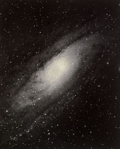
Plate 1
The Great Nebula in Andromeda
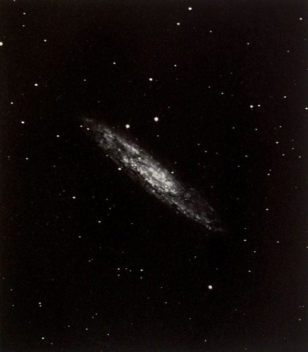
Plate 2
The Spiral Nebula H.V.I. Ceti
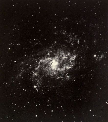
Plate 3
The Spiral Nebula M.33 Trianguli
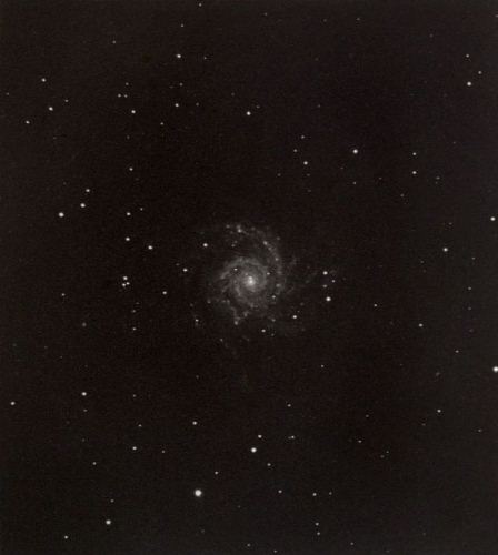
Plate 4
The Spiral Nebula M.74 Piscium
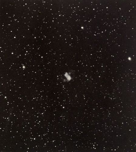
Plate 5
The Nebula M.76 Persei
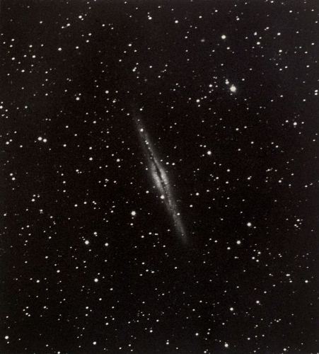
Plate 6
The Nebula H.V. 19 Andromedae
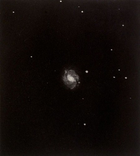
Plate 7
The Spiral Nebula M.77 Ceti
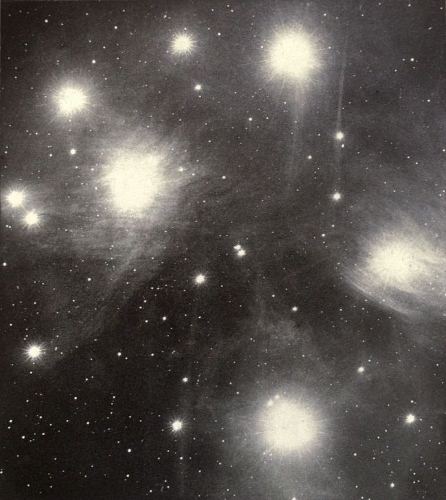
Plate 8
The Pleiades
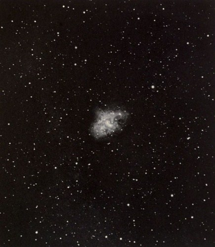
Plate 9
The Crab Nebula in Taurus
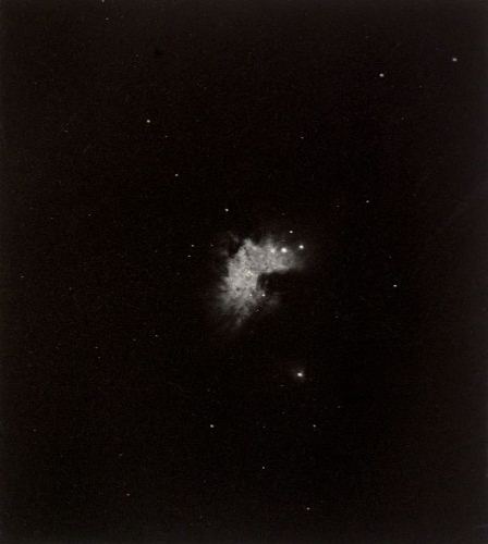
Plate 11
Central Portion of the Great Nebula in Orion
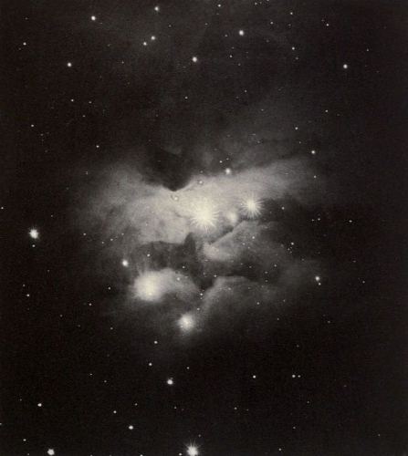
Plate 12
The Nebula H.V. 30, Orionis
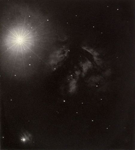
Plate 13
The Nebula H.V. 28 Orionis
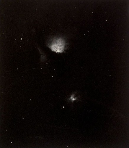
Plate 14
The Nebula M.78 Orionis
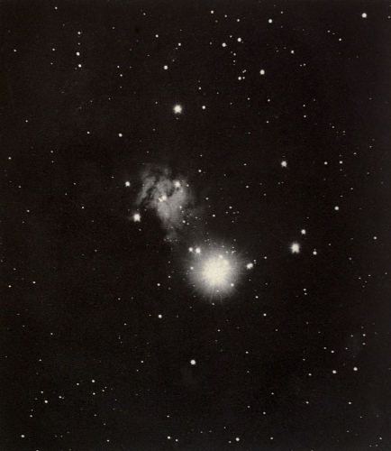
Plate 15
Nebula near 15 Monocerotis
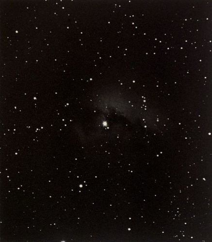
Plate 16
New Nebula in Monoceros (Roberts)
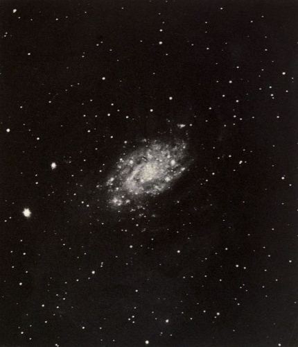
Plate 17
The Spiral Nebula H.V.44 Camelopardi
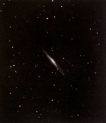
Plate 18
The Nebula H.I.200 Leonis Minoris
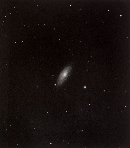
Plate 19
The Spiral Nebula H.I.205 Ursae Majoris
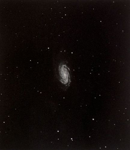
Plate 20
The Spiral Nebula H.I.56-57 Leonis
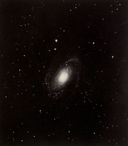
Plate 21
The Spiral Nebula M 81, Ursae Majoris
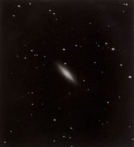
Plate 22
The Nebula H.I.163, Sextantis
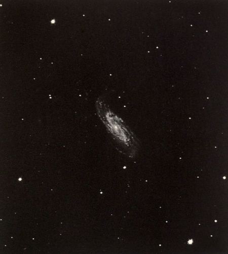
Plate 23
The Spiral Nebula H.I.199, Ursae Majoris
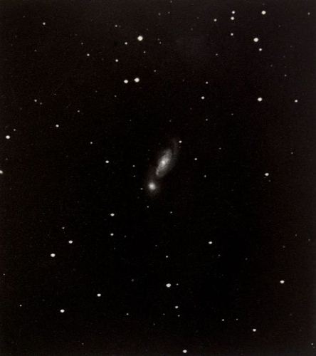
Plate 24
The Double Nebula H.II 28-29, Leonis
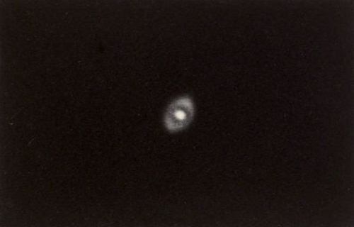
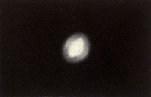
Plate 25
The Planetary Nebula H.IV 27, Hydrae
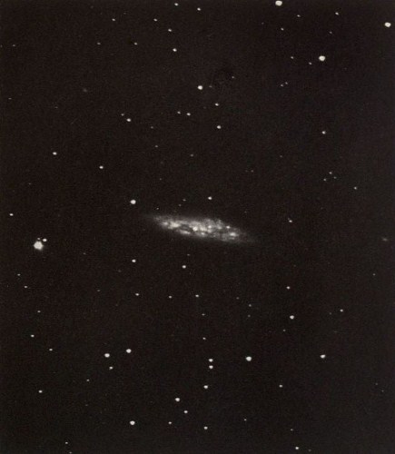
Plate 26
The Nebula H.V 46, Ursae Majoris
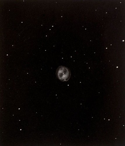
Plate 27
The Owl Nebula, M 97, Ursae Majoris
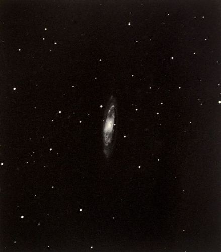
Plate 28
The Spiral Nebula M 65, Leonis
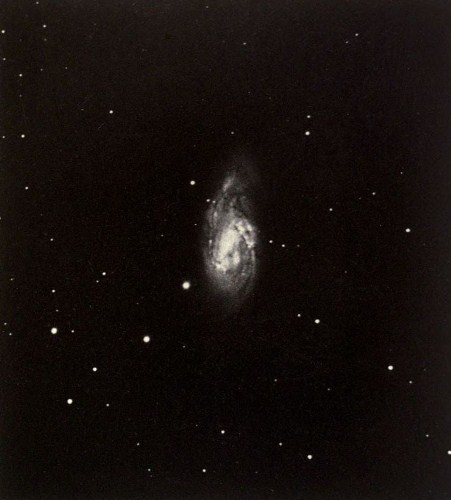
Plate 29
The Spiral Nebula M 66, Leonis
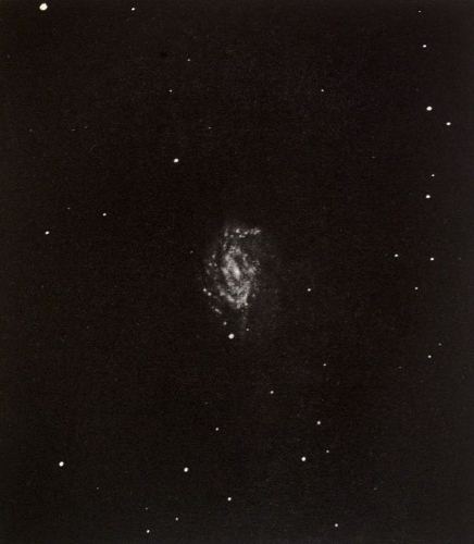
Plate 30 A
The Spiral Nebula H.II, 730, Ursae Majoris
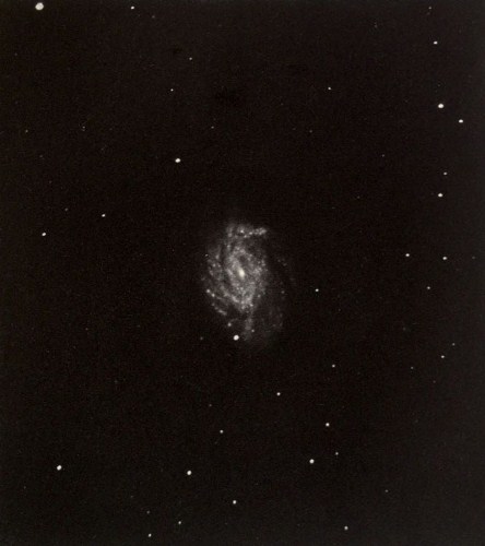
Plate 30 B
The Spiral Nebula H.II, 730, Ursae Majoris
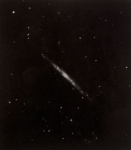
Plate 31
The Nebula H.V 41, Canum Venaticorum
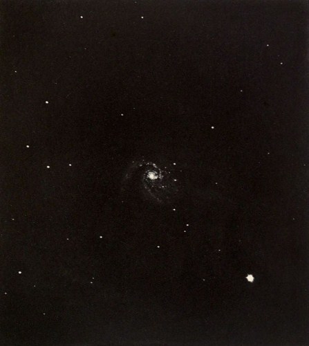
Plate 32
The Spiral Nebula M 99, Comae Berenices
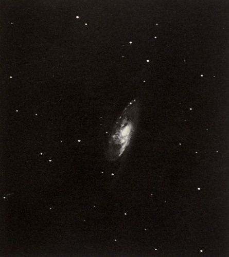
Plate 33
The Spiral Nebula H.V 43, Ursae Majoris
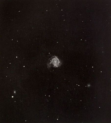
Plate 34
The Spiral Nebula M 61, Virginis
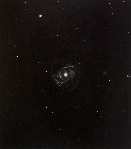
Plate 35
The Spiral Nebula M 100, Comae Berenices
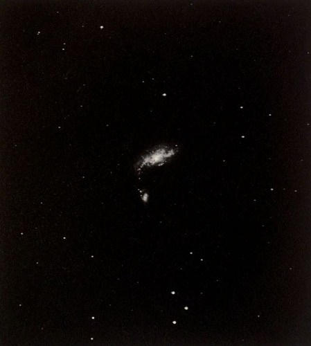
Plate 36
The Nebula H.I 197-198, Canum Venaticorum
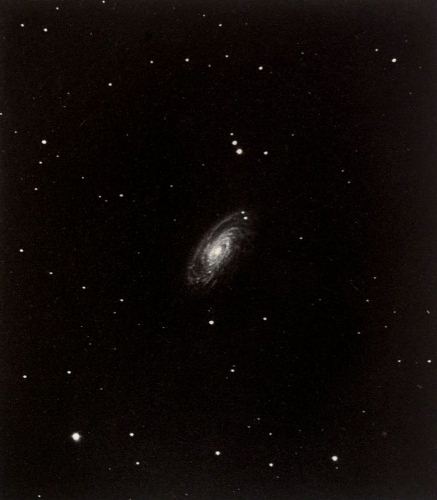
Plate 37
The Spiral Nebula M 88, Comae Berenices
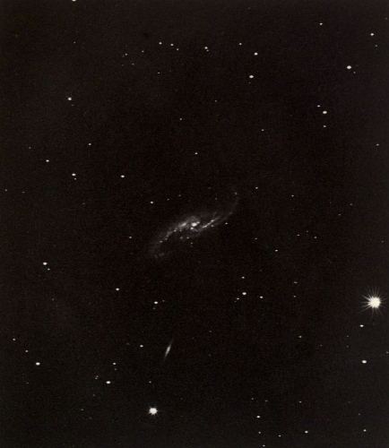
Plate 38
The Spiral Nebula H.V 2, Virginis
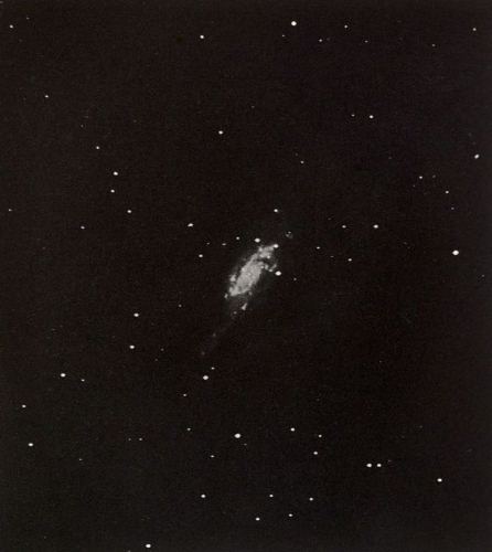
Plate 39
The Spiral Nebula H.I 92, Comae Berenices
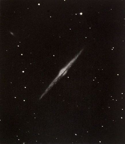
Plate 40
The Nebula H.V 24, Comae Berenices
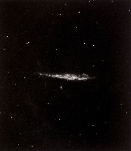
Plate 41
The Nebula H.V 42, Comae Berenices
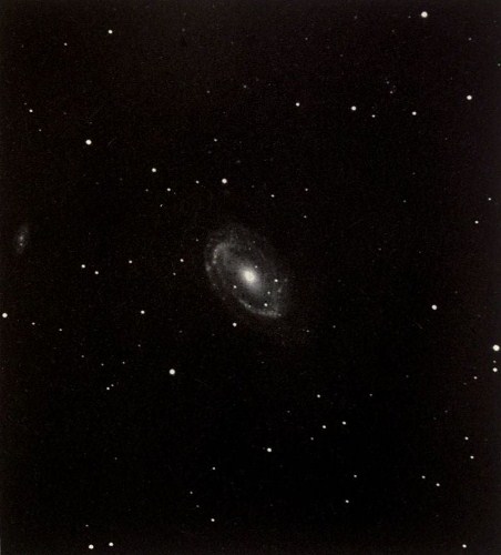
Plate 42
The Spiral Nebula H.I 84, Comae Berenices
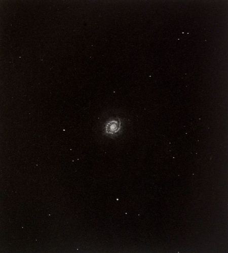
Plate 43
The Spiral Nebula M 94, Canum Venaticorum
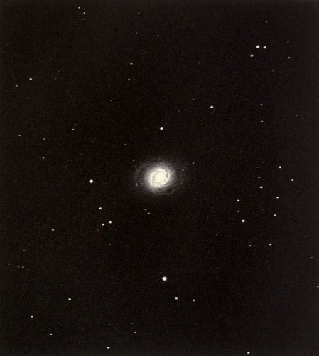
Plate 44
The Spiral Nebula M 94 Canum Venaticorum
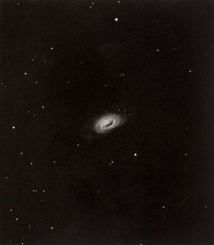
Plate 45
The Spiral Nebula M 64, Comae Berenices
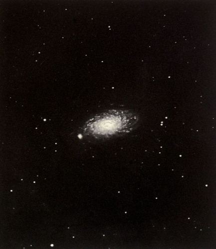
Plate 46
The Spiral Nebula M 63, Canum Venaticorum
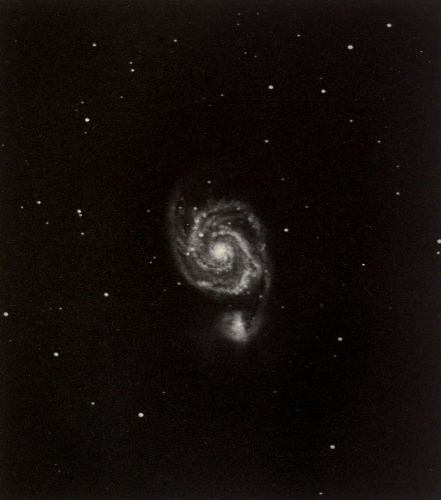
Plate 47
The Spiral Nebula M 51, Canum Venaticorum
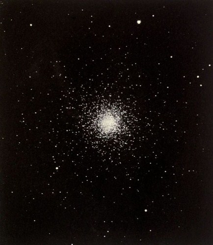
Plate 48
The Star Cluster M 3, Canum Venaticorum
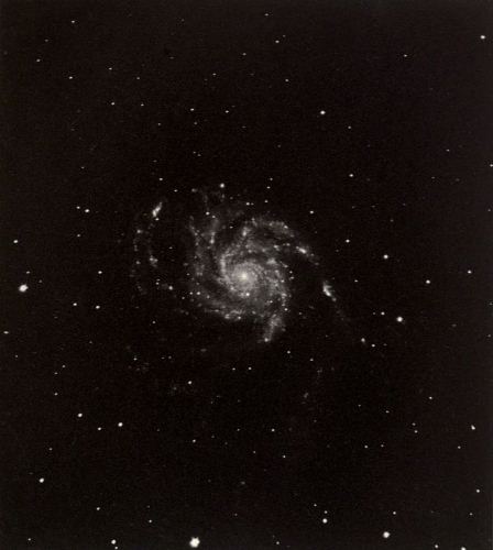
Plate 49
The Spiral Nebula M 101, Ursae Majoris
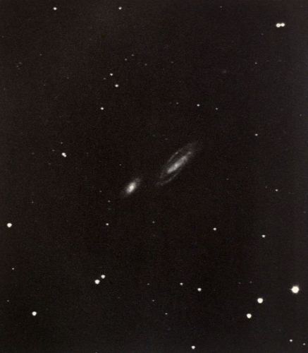
Plate 50
The Double Nebula H.II 751-752, Bootis
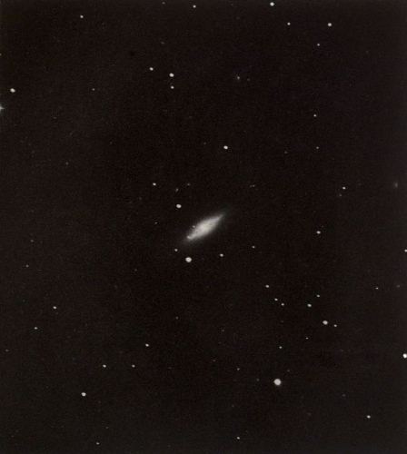
Plate 51
The Nebula H.I 215, Draconis
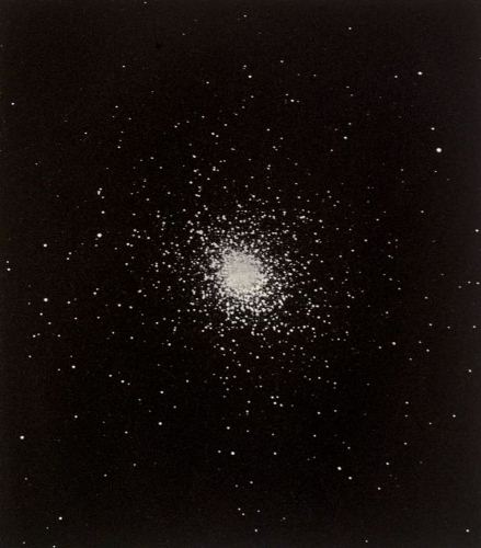
Plate 52
The Star Cluster M 5, Librae
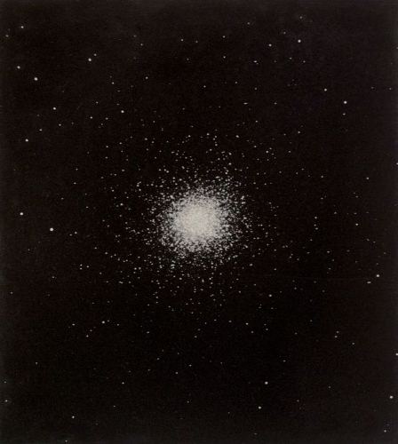
Plate 53
The Star Cluster M 13, Herculis
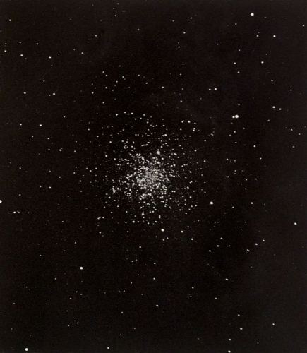
Plate 54
The Star Cluster M 12, Ophiuchi
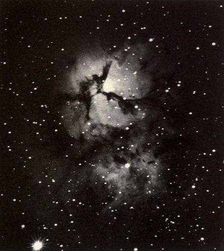
Plate 55
The Trifid Nebula, M 20, Sagittarii
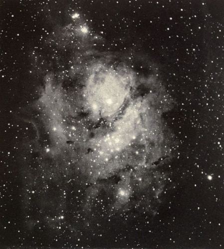
Plate 56
The Nebula M 8, Sagittarii
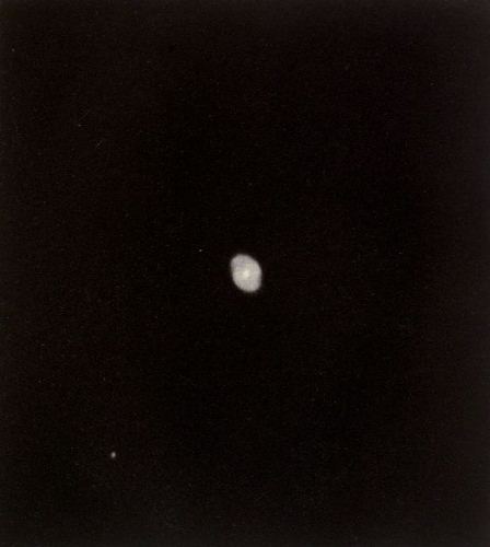
Plate 57
The Planetary Nebula H.IV 37, Draconis
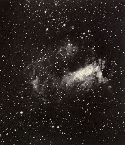
Plate 58
The Horse Shoe Or Omega Nebula M 17, Sagittarii
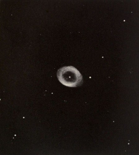
Plate 59
The Ring Nebula, M.57, in Lyra
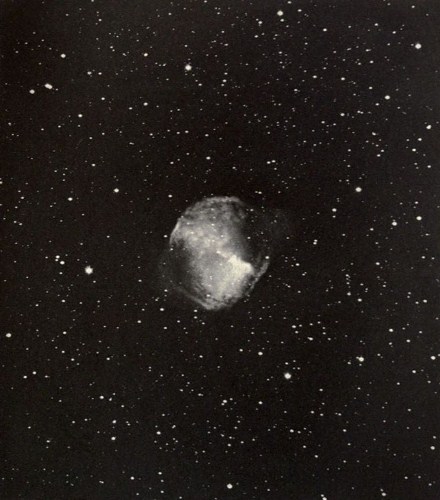
Plate 60
The Dumb-Bell Nebula in Vulpecula
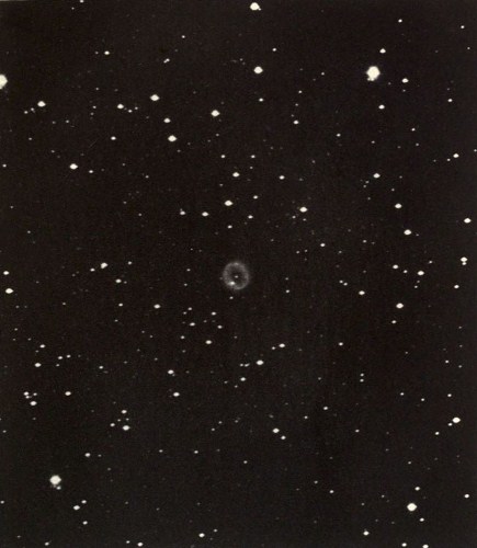
Plate 61
The Annular Nebula H.IV 13, Cygni
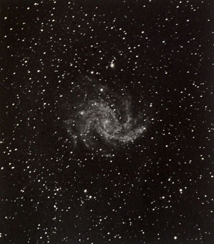
Plate 62
The Spiral Nebula H.IV 76, Cephei
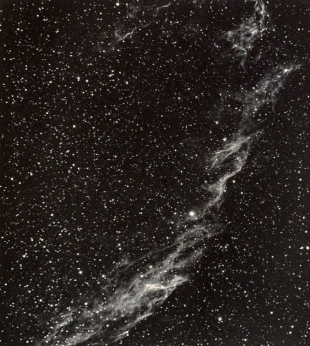
Plate 63
The Net-work Nebula in Cygnus
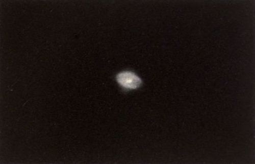
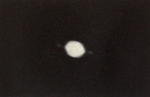
Plate 64
The Planetary Nebula H.IV 1, Aquarii
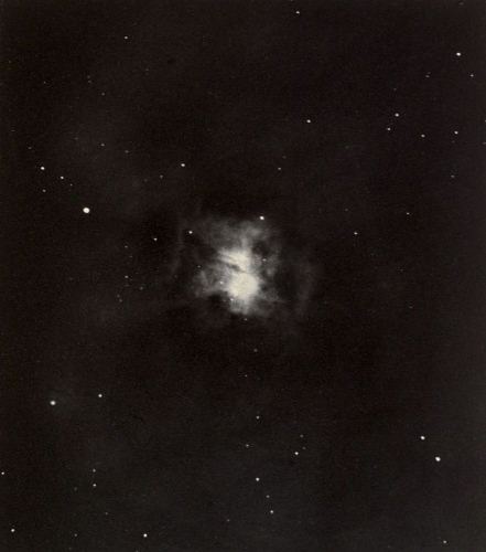
Plate 65
The Nebula H.Iv 74, Cephei
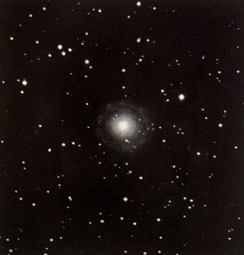
Plate 66
The Nebula H.II 207, Pegasi
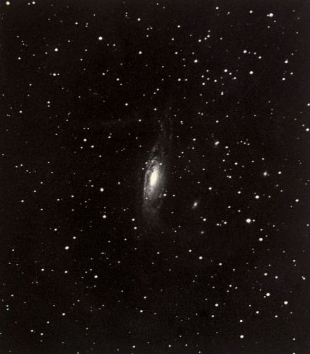
Plate 67
The Spiral Nebula H.I 53, Pegasi
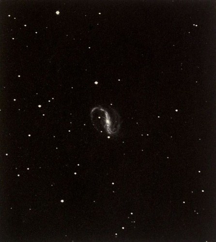
Plate 68
The Spiral Nebula H.I 55, Pegasi
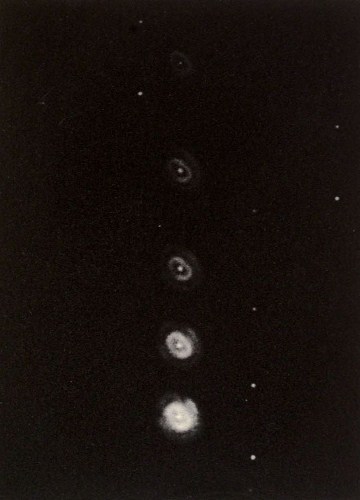
Plate 69
The Planetary Nebula H.IV 18, Andromedae
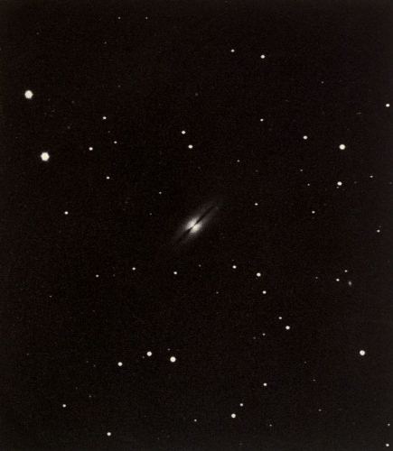
Plate 70
The Nebula H.II 240, Pegasi
Footnotes:
[1] Reprinted from The Astrophysical Journal, 11, 325, 1900.
[2] For a more complete history of this part of the subject, see Dr. Holden’s articles in Pub. Ast. Soc. Pacific, 7, 197 et seq., 1895.
[3] The difficulties here referred to, about which a good deal has been written, seem to have had their origin in the fact that it was impossible, at the time of the preliminary trials, to provide the observer with an assistant, while the Crossley reflector is practically unmanageable by a single person.
[4] Mon. Not. R. A. S., 48, 386.
[5] Kindly lent by the Astronomical Society of the Pacific.
[6] Mem. R. A. S., 46, 173.
[7] Mon. Not. R. A. S., 48, 280, 1888.
[8] Mon. Not. R. A. S., 49, 297. The construction here described is not followed exactly in the Crossley apparatus. The guiding eyepiece slides freely when not held by a clamp. Pin-holes for preventing fogging are unnecessary when red light is used.
[9] It so happens that the tension of the vertical thread is such that it begins to slacken when the temperature falls to within about 2° of the dew point. The thread thus forms an excellent hygrometer, which is constantly under the eye of the observer. When the thread becomes slack, it is time to cover the mirrors.
[10] Mon. Not. R. A. S., 48, 352.
[11] The following list includes all papers of interest:
“Photographic Observations of Comet I, 1898 (Brooks), made with the Crossley Reflector of the Lick Observatory.” A. J. No. 451, 19, 151; see also Ap. J., 8, 287.
“The Small Bright Nebula near Merope,” Pub. A. S. P., 10, 245.
“On Some Photographs of the Great Nebula in Orion, taken by means of the Less Refrangible Rays in its Spectrum,” Ap. J., 9, 133. See also Pub. A. S. P., 11, 70; Ap. J., 10, 167; A. N., 3601.
“Small Nebulæ discovered with the Crossley Reflector of the Lick Observatory,” Mon. Not. R. A. S., 59, 537.
“The Ring Nebula in Lyra,” Ap. J., 10, 193.
“The Annular Nebula H. IV. 13 in Cygnus,” Ap. J., 10, 266; see also Pub. A. S. P., 11, 177.
“On the Predominance of Spiral Forms among the Nebulæ,” A. N., 3601.
“The Distribution of Stars in the Cluster Messier 13 in Hercules” (by H. K. Palmer), Ap. J., 10, 246.
“The Photographic Efficiency of the Crossley Reflector,” Pub. A. S. P., 11, 199; Observatory, 22, 437.
“New Nebulæ discovered photographically with the Crossley Reflector of the Lick Observatory,” Mon. Not. R. A. S., 60, 128.
“The Spiral Nebula, H. I., 55 Pegasi,” Ap. J., 11, 1.
“Photographic Observations of Hind’s Variable Nebula in Taurus, made with the Crossley Reflector of the Lick Observatory,” Mon. Not. R. A. S., 60, 424.
“Use of the Crossley Reflector for Photographic Measurements of Position,” Pub. A. S. P., 12, 73.
“Discovery and Photographic Observations of a New Asteroid 1899 FD.,” A. N., 3635.
“Elements of Asteroid 1899 FD.” (by H. K. Palmer), A. N. 3635.
[12] Footnote added in 1908: This concluding paragraph, retained in the present publication for completeness, loses point in some particulars, because the photogravure referred to is not reproduced here. The heliogravure reproduction of the Trifid nebula is No. 55.
[13] Since then a photograph by Dr. Roberts has appeared in Knowledge, 23, 35, February, 1900.
End of the Project Gutenberg EBook of Photographs of Nebulæ and Clusters, by
James Edward Keeler

*** END OF THIS PROJECT GUTENBERG EBOOK PHOTOGRAPHS OF NEBULÆ AND CLUSTERS ***

***** This file should be named 36470-h.htm or 36470-h.zip *****
This and all associated files of various formats will be found in:
        http://www.gutenberg.org/3/6/4/7/36470/

Produced by Bryan Ness and the Online Distributed
Proofreading Team at http://www.pgdp.net (This file was
produced from images generously made available by The
Internet Archive/American Libraries.)


Updated editions will replace the previous one--the old editions
will be renamed.

Creating the works from public domain print editions means that no
one owns a United States copyright in these works, so the Foundation
(and you!) can copy and distribute it in the United States without
permission and without paying copyright royalties.  Special rules,
set forth in the General Terms of Use part of this license, apply to
copying and distributing Project Gutenberg-tm electronic works to
protect the PROJECT GUTENBERG-tm concept and trademark.  Project
Gutenberg is a registered trademark, and may not be used if you
charge for the eBooks, unless you receive specific permission.  If you
do not charge anything for copies of this eBook, complying with the
rules is very easy.  You may use this eBook for nearly any purpose
such as creation of derivative works, reports, performances and
research.  They may be modified and printed and given away--you may do
practically ANYTHING with public domain eBooks.  Redistribution is
subject to the trademark license, especially commercial
redistribution.


*** START: FULL LICENSE ***

THE FULL PROJECT GUTENBERG LICENSE
PLEASE READ THIS BEFORE YOU DISTRIBUTE OR USE THIS WORK

To protect the Project Gutenberg-tm mission of promoting the free
distribution of electronic works, by using or distributing this work
(or any other work associated in any way with the phrase "Project
Gutenberg"), you agree to comply with all the terms of the Full Project
Gutenberg-tm License (available with this file or online at
http://gutenberg.org/license).


Section 1.  General Terms of Use and Redistributing Project Gutenberg-tm
electronic works

1.A.  By reading or using any part of this Project Gutenberg-tm
electronic work, you indicate that you have read, understand, agree to
and accept all the terms of this license and intellectual property
(trademark/copyright) agreement.  If you do not agree to abide by all
the terms of this agreement, you must cease using and return or destroy
all copies of Project Gutenberg-tm electronic works in your possession.
If you paid a fee for obtaining a copy of or access to a Project
Gutenberg-tm electronic work and you do not agree to be bound by the
terms of this agreement, you may obtain a refund from the person or
entity to whom you paid the fee as set forth in paragraph 1.E.8.

1.B.  "Project Gutenberg" is a registered trademark.  It may only be
used on or associated in any way with an electronic work by people who
agree to be bound by the terms of this agreement.  There are a few
things that you can do with most Project Gutenberg-tm electronic works
even without complying with the full terms of this agreement.  See
paragraph 1.C below.  There are a lot of things you can do with Project
Gutenberg-tm electronic works if you follow the terms of this agreement
and help preserve free future access to Project Gutenberg-tm electronic
works.  See paragraph 1.E below.

1.C.  The Project Gutenberg Literary Archive Foundation ("the Foundation"
or PGLAF), owns a compilation copyright in the collection of Project
Gutenberg-tm electronic works.  Nearly all the individual works in the
collection are in the public domain in the United States.  If an
individual work is in the public domain in the United States and you are
located in the United States, we do not claim a right to prevent you from
copying, distributing, performing, displaying or creating derivative
works based on the work as long as all references to Project Gutenberg
are removed.  Of course, we hope that you will support the Project
Gutenberg-tm mission of promoting free access to electronic works by
freely sharing Project Gutenberg-tm works in compliance with the terms of
this agreement for keeping the Project Gutenberg-tm name associated with
the work.  You can easily comply with the terms of this agreement by
keeping this work in the same format with its attached full Project
Gutenberg-tm License when you share it without charge with others.

1.D.  The copyright laws of the place where you are located also govern
what you can do with this work.  Copyright laws in most countries are in
a constant state of change.  If you are outside the United States, check
the laws of your country in addition to the terms of this agreement
before downloading, copying, displaying, performing, distributing or
creating derivative works based on this work or any other Project
Gutenberg-tm work.  The Foundation makes no representations concerning
the copyright status of any work in any country outside the United
States.

1.E.  Unless you have removed all references to Project Gutenberg:

1.E.1.  The following sentence, with active links to, or other immediate
access to, the full Project Gutenberg-tm License must appear prominently
whenever any copy of a Project Gutenberg-tm work (any work on which the
phrase "Project Gutenberg" appears, or with which the phrase "Project
Gutenberg" is associated) is accessed, displayed, performed, viewed,
copied or distributed:

This eBook is for the use of anyone anywhere at no cost and with
almost no restrictions whatsoever.  You may copy it, give it away or
re-use it under the terms of the Project Gutenberg License included
with this eBook or online at www.gutenberg.org

1.E.2.  If an individual Project Gutenberg-tm electronic work is derived
from the public domain (does not contain a notice indicating that it is
posted with permission of the copyright holder), the work can be copied
and distributed to anyone in the United States without paying any fees
or charges.  If you are redistributing or providing access to a work
with the phrase "Project Gutenberg" associated with or appearing on the
work, you must comply either with the requirements of paragraphs 1.E.1
through 1.E.7 or obtain permission for the use of the work and the
Project Gutenberg-tm trademark as set forth in paragraphs 1.E.8 or
1.E.9.

1.E.3.  If an individual Project Gutenberg-tm electronic work is posted
with the permission of the copyright holder, your use and distribution
must comply with both paragraphs 1.E.1 through 1.E.7 and any additional
terms imposed by the copyright holder.  Additional terms will be linked
to the Project Gutenberg-tm License for all works posted with the
permission of the copyright holder found at the beginning of this work.

1.E.4.  Do not unlink or detach or remove the full Project Gutenberg-tm
License terms from this work, or any files containing a part of this
work or any other work associated with Project Gutenberg-tm.

1.E.5.  Do not copy, display, perform, distribute or redistribute this
electronic work, or any part of this electronic work, without
prominently displaying the sentence set forth in paragraph 1.E.1 with
active links or immediate access to the full terms of the Project
Gutenberg-tm License.

1.E.6.  You may convert to and distribute this work in any binary,
compressed, marked up, nonproprietary or proprietary form, including any
word processing or hypertext form.  However, if you provide access to or
distribute copies of a Project Gutenberg-tm work in a format other than
"Plain Vanilla ASCII" or other format used in the official version
posted on the official Project Gutenberg-tm web site (www.gutenberg.org),
you must, at no additional cost, fee or expense to the user, provide a
copy, a means of exporting a copy, or a means of obtaining a copy upon
request, of the work in its original "Plain Vanilla ASCII" or other
form.  Any alternate format must include the full Project Gutenberg-tm
License as specified in paragraph 1.E.1.

1.E.7.  Do not charge a fee for access to, viewing, displaying,
performing, copying or distributing any Project Gutenberg-tm works
unless you comply with paragraph 1.E.8 or 1.E.9.

1.E.8.  You may charge a reasonable fee for copies of or providing
access to or distributing Project Gutenberg-tm electronic works provided
that

- You pay a royalty fee of 20% of the gross profits you derive from
     the use of Project Gutenberg-tm works calculated using the method
     you already use to calculate your applicable taxes.  The fee is
     owed to the owner of the Project Gutenberg-tm trademark, but he
     has agreed to donate royalties under this paragraph to the
     Project Gutenberg Literary Archive Foundation.  Royalty payments
     must be paid within 60 days following each date on which you
     prepare (or are legally required to prepare) your periodic tax
     returns.  Royalty payments should be clearly marked as such and
     sent to the Project Gutenberg Literary Archive Foundation at the
     address specified in Section 4, "Information about donations to
     the Project Gutenberg Literary Archive Foundation."

- You provide a full refund of any money paid by a user who notifies
     you in writing (or by e-mail) within 30 days of receipt that s/he
     does not agree to the terms of the full Project Gutenberg-tm
     License.  You must require such a user to return or
     destroy all copies of the works possessed in a physical medium
     and discontinue all use of and all access to other copies of
     Project Gutenberg-tm works.

- You provide, in accordance with paragraph 1.F.3, a full refund of any
     money paid for a work or a replacement copy, if a defect in the
     electronic work is discovered and reported to you within 90 days
     of receipt of the work.

- You comply with all other terms of this agreement for free
     distribution of Project Gutenberg-tm works.

1.E.9.  If you wish to charge a fee or distribute a Project Gutenberg-tm
electronic work or group of works on different terms than are set
forth in this agreement, you must obtain permission in writing from
both the Project Gutenberg Literary Archive Foundation and Michael
Hart, the owner of the Project Gutenberg-tm trademark.  Contact the
Foundation as set forth in Section 3 below.

1.F.

1.F.1.  Project Gutenberg volunteers and employees expend considerable
effort to identify, do copyright research on, transcribe and proofread
public domain works in creating the Project Gutenberg-tm
collection.  Despite these efforts, Project Gutenberg-tm electronic
works, and the medium on which they may be stored, may contain
"Defects," such as, but not limited to, incomplete, inaccurate or
corrupt data, transcription errors, a copyright or other intellectual
property infringement, a defective or damaged disk or other medium, a
computer virus, or computer codes that damage or cannot be read by
your equipment.

1.F.2.  LIMITED WARRANTY, DISCLAIMER OF DAMAGES - Except for the "Right
of Replacement or Refund" described in paragraph 1.F.3, the Project
Gutenberg Literary Archive Foundation, the owner of the Project
Gutenberg-tm trademark, and any other party distributing a Project
Gutenberg-tm electronic work under this agreement, disclaim all
liability to you for damages, costs and expenses, including legal
fees.  YOU AGREE THAT YOU HAVE NO REMEDIES FOR NEGLIGENCE, STRICT
LIABILITY, BREACH OF WARRANTY OR BREACH OF CONTRACT EXCEPT THOSE
PROVIDED IN PARAGRAPH 1.F.3. YOU AGREE THAT THE FOUNDATION, THE
TRADEMARK OWNER, AND ANY DISTRIBUTOR UNDER THIS AGREEMENT WILL NOT BE
LIABLE TO YOU FOR ACTUAL, DIRECT, INDIRECT, CONSEQUENTIAL, PUNITIVE OR
INCIDENTAL DAMAGES EVEN IF YOU GIVE NOTICE OF THE POSSIBILITY OF SUCH
DAMAGE.

1.F.3.  LIMITED RIGHT OF REPLACEMENT OR REFUND - If you discover a
defect in this electronic work within 90 days of receiving it, you can
receive a refund of the money (if any) you paid for it by sending a
written explanation to the person you received the work from.  If you
received the work on a physical medium, you must return the medium with
your written explanation.  The person or entity that provided you with
the defective work may elect to provide a replacement copy in lieu of a
refund.  If you received the work electronically, the person or entity
providing it to you may choose to give you a second opportunity to
receive the work electronically in lieu of a refund.  If the second copy
is also defective, you may demand a refund in writing without further
opportunities to fix the problem.

1.F.4.  Except for the limited right of replacement or refund set forth
in paragraph 1.F.3, this work is provided to you 'AS-IS' WITH NO OTHER
WARRANTIES OF ANY KIND, EXPRESS OR IMPLIED, INCLUDING BUT NOT LIMITED TO
WARRANTIES OF MERCHANTIBILITY OR FITNESS FOR ANY PURPOSE.

1.F.5.  Some states do not allow disclaimers of certain implied
warranties or the exclusion or limitation of certain types of damages.
If any disclaimer or limitation set forth in this agreement violates the
law of the state applicable to this agreement, the agreement shall be
interpreted to make the maximum disclaimer or limitation permitted by
the applicable state law.  The invalidity or unenforceability of any
provision of this agreement shall not void the remaining provisions.

1.F.6.  INDEMNITY - You agree to indemnify and hold the Foundation, the
trademark owner, any agent or employee of the Foundation, anyone
providing copies of Project Gutenberg-tm electronic works in accordance
with this agreement, and any volunteers associated with the production,
promotion and distribution of Project Gutenberg-tm electronic works,
harmless from all liability, costs and expenses, including legal fees,
that arise directly or indirectly from any of the following which you do
or cause to occur: (a) distribution of this or any Project Gutenberg-tm
work, (b) alteration, modification, or additions or deletions to any
Project Gutenberg-tm work, and (c) any Defect you cause.


Section  2.  Information about the Mission of Project Gutenberg-tm

Project Gutenberg-tm is synonymous with the free distribution of
electronic works in formats readable by the widest variety of computers
including obsolete, old, middle-aged and new computers.  It exists
because of the efforts of hundreds of volunteers and donations from
people in all walks of life.

Volunteers and financial support to provide volunteers with the
assistance they need, are critical to reaching Project Gutenberg-tm's
goals and ensuring that the Project Gutenberg-tm collection will
remain freely available for generations to come.  In 2001, the Project
Gutenberg Literary Archive Foundation was created to provide a secure
and permanent future for Project Gutenberg-tm and future generations.
To learn more about the Project Gutenberg Literary Archive Foundation
and how your efforts and donations can help, see Sections 3 and 4
and the Foundation web page at http://www.pglaf.org.


Section 3.  Information about the Project Gutenberg Literary Archive
Foundation

The Project Gutenberg Literary Archive Foundation is a non profit
501(c)(3) educational corporation organized under the laws of the
state of Mississippi and granted tax exempt status by the Internal
Revenue Service.  The Foundation's EIN or federal tax identification
number is 64-6221541.  Its 501(c)(3) letter is posted at
http://pglaf.org/fundraising.  Contributions to the Project Gutenberg
Literary Archive Foundation are tax deductible to the full extent
permitted by U.S. federal laws and your state's laws.

The Foundation's principal office is located at 4557 Melan Dr. S.
Fairbanks, AK, 99712., but its volunteers and employees are scattered
throughout numerous locations.  Its business office is located at
809 North 1500 West, Salt Lake City, UT 84116, (801) 596-1887, email
business@pglaf.org.  Email contact links and up to date contact
information can be found at the Foundation's web site and official
page at http://pglaf.org

For additional contact information:
     Dr. Gregory B. Newby
     Chief Executive and Director
     gbnewby@pglaf.org


Section 4.  Information about Donations to the Project Gutenberg
Literary Archive Foundation

Project Gutenberg-tm depends upon and cannot survive without wide
spread public support and donations to carry out its mission of
increasing the number of public domain and licensed works that can be
freely distributed in machine readable form accessible by the widest
array of equipment including outdated equipment.  Many small donations
($1 to $5,000) are particularly important to maintaining tax exempt
status with the IRS.

The Foundation is committed to complying with the laws regulating
charities and charitable donations in all 50 states of the United
States.  Compliance requirements are not uniform and it takes a
considerable effort, much paperwork and many fees to meet and keep up
with these requirements.  We do not solicit donations in locations
where we have not received written confirmation of compliance.  To
SEND DONATIONS or determine the status of compliance for any
particular state visit http://pglaf.org

While we cannot and do not solicit contributions from states where we
have not met the solicitation requirements, we know of no prohibition
against accepting unsolicited donations from donors in such states who
approach us with offers to donate.

International donations are gratefully accepted, but we cannot make
any statements concerning tax treatment of donations received from
outside the United States.  U.S. laws alone swamp our small staff.

Please check the Project Gutenberg Web pages for current donation
methods and addresses.  Donations are accepted in a number of other
ways including checks, online payments and credit card donations.
To donate, please visit: http://pglaf.org/donate


Section 5.  General Information About Project Gutenberg-tm electronic
works.

Professor Michael S. Hart is the originator of the Project Gutenberg-tm
concept of a library of electronic works that could be freely shared
with anyone.  For thirty years, he produced and distributed Project
Gutenberg-tm eBooks with only a loose network of volunteer support.


Project Gutenberg-tm eBooks are often created from several printed
editions, all of which are confirmed as Public Domain in the U.S.
unless a copyright notice is included.  Thus, we do not necessarily
keep eBooks in compliance with any particular paper edition.


Most people start at our Web site which has the main PG search facility:

     http://www.gutenberg.org

This Web site includes information about Project Gutenberg-tm,
including how to make donations to the Project Gutenberg Literary
Archive Foundation, how to help produce our new eBooks, and how to
subscribe to our email newsletter to hear about new eBooks.