

BY MEMBERS OF THE STAFF OF BELL TELEPHONE LABORATORIES
EDITOR: RONALD M. FOSTER, Jr.
How scientists and engineers use basic physical principles to solve some of the problems in communicating by means of man-made satellites
© 1963 Bell Telephone Laboratories, Incorporated
All rights reserved.
Permission to reproduce any material contained in this book must be obtained, in writing, from the publisher.
Library of Congress Catalog Card Number 63-21667
Printed in U.S.A.
John R. Pierce
Executive Director, Research,
Communications Principles and Communications Systems
Bell Telephone Laboratories
When I first talked about the possibilities and advantages of communications satellites to the Princeton Section of the Institute of Radio Engineers on the evening of October 14, 1954, I was diligent in my analysis and enthusiastic in my presentation but, I must confess, a little skeptical as to whether or not anything would come of the idea.
Still, others and I at Bell Laboratories remained interested, and, after the launching of Sputnik I on November 3, 1957, and of Explorer I on January 31, 1958, we worked actively toward satellite communications experiments. This led to our work with Echo I (launched August 12, 1960) and finally to the launching on July 10, 1962, of Telstar I—that satellite which became, in the words of Queen Elizabeth, “the invisible focus of a million eyes.”
This work on communications satellites has been a grand exploration and opening up of a hitherto dark continent of science and technology. My courageous friends at Bell Laboratories encountered therein surprising difficulties and perplexing problems which I had never dreamed of, and these intrepid and indefatigable adventurers grappled with them and mastered them all.
Now you, who have in your own homes seen pictures transmitted across the ocean by satellite, can learn first hand from the men who worked on hard and varied technical problems just what these problems were and how they were solved. And, by reading you can find out what sort of knowledge, training, and habits you yourself will need if you wish some day to adventure into those undiscovered or unexplored fields of technology which will be new and exciting when Telstar has become old hat.
June 5, 1963
Information about these and other materials is available to teachers from local Telephone Company business offices
Despite the title, this is not a physics textbook, and it will tell you only part of the fascinating story of satellite communications. However, we have tried to tell this story in a rather special way. Part I explains why we are so interested in communicating by means of man-made satellites, describes the important events in the progress of satellite communications (with special emphasis on Project Telstar), and points out some of the very knotty problems that had to be solved. Then, in Part II, we pick out six typical satellite communications problems and go into them more deeply.
These case histories are examples of the things scientists and engineers are constantly faced with. To narrate them we have called on six experts—Bell Telephone Laboratories engineers and scientists who actually have been working on the problems. The second half of our book is taken up by their accounts of their own personal experiences. We hope that reading them will give you an insight into what it is really like to be a scientist or engineer working in a laboratory on an important new venture into the future. We hope you will see that what they do is not all excitement and glamour. It involves hard work, ingenious thinking, and plugging away at tough problems. But this is what scientists and engineers enjoy—along with the excitement and glamour, of course.
Only a part of what our authors talk about can strictly be called “physics”—it is also engineering, chemistry, mathematics, and even psychology. 9 But almost all their work is based—when you get down to fundamentals—on basic principles of classical physics taught in high school.
Now, a word of caution. In Part I, in talking about satellite communications in general, we have kept things at a level that should be understandable to almost everyone—even those who have never taken a high school science course. But we warn you this isn’t true of Part II. Our authors have tried to tell their stories as carefully and as logically as possible, but some readers may have trouble in following all they say. This we expect. We haven’t tried to sugar-coat or gloss over any essential details of the problems or their solutions. We don’t want you to think that solving them was any easier than it actually was. And, since this is not intended as a textbook, we may sometimes omit elementary material and go right to the heart of the matter.
When this book was written satellite communications was still a technological infant. It is growing and changing so swiftly that much of what we say may soon be out of date. That can’t be helped, of course, and we ask you—who may be reading it long afterward—to be tolerant. Our problems may well be forgotten when new, more sophisticated ones appear. But we are dealing here in methods, not in history; the ways in which these problems were attacked are just as lasting and important as the problems themselves.

“Our intensive research and development in the field of communications satellites have brought us to the point where we are now certain of the technical feasibility of transmitting messages to any part of the world by directing them to satellites.... The actual operation of such a system would provide a dramatic demonstration of our leadership in this area of space activity.... The direct benefits—economic, educational, and political—of this improved world-wide communication will be invaluable.” —JOHN F. KENNEDY
That’s a good question to begin with. Why should we get involved in a vast, complicated program such as communication by means of man-made satellites? Is the end result really worth all the trouble that is involved? As you go further, you will see that nothing to do with satellite communications is as simple as it first seems. Even some of the easier questions have been answered only after long hours of perceptive thinking, ingenious experimenting, and shrewd deduction. They have required a lot of hard work, led to many frustrating difficulties, and cost quite a bit of money. But the answer still is yes. Despite all the difficulties, it is clear that the creation of a successful satellite communicating system is worth it.
There is a double reason for this. On the one hand, it is a technological target that is now clearly within our range. We must either reach it or let 12 progress pass us by. Satellite communications is one field in which, as far as we know, American engineering and science have been well in the lead—so we have an even greater incentive to press on in this direction as hard and as fast as we can.
But perhaps more important than the prestige it would give our country is a second reason for our great interest in satellite communications: We need it. The world today is going through one of its great periods of change. This has caused many complications, and one of the most important is the need for much better communications between nations and peoples. By “communications” we mean all the various ways of sending information from one place to another: mail, telephone calls, business data, radio, television. The demand for these services—especially when we look ahead to the 1970’s and 1980’s—will be tremendous. Our international communications channels will be completely swamped unless some major improvements are made.
Fortunately, modern technology—given a boost by the world’s interest in rockets, missiles, and the exploration of space—has shown us one answer to this problem: the communications satellite. The conventional pathways for long-distance communication have led along the earth’s surface, under the oceans, and through the lower atmosphere. No one of these routes has yet provided all the capacity, speed, or quality we need. Present underseas cables have a limited capacity; surface travel by ship is too slow for anything but routine mail; short-wave radio is subject to distortion and noise, and the available frequencies are rapidly being used up. Although jet planes can span the oceans in a few hours with mail and such things as taped television shows, the big need will be to send information instantaneously. And the communications satellite offers us a very promising way to do this.
One of the attractive things about using a satellite is that it doesn’t require a revolutionary breakthrough in technical knowledge. It can employ a satisfactory means of communicating that is already available: the microwave radio relay. Today, this kind of transmission is used on a routine basis to send thousands of telephone calls and television programs across long distances. It gives high-quality performance and has a large message capacity. But there has always been one difficulty keeping us from using it for overseas communications: Extremely high frequency 13 waves can travel almost unlimited distances, but they can go only in straight lines. This means that the curvature of the earth limits a microwave’s line-of-sight path to about 30 miles; so we must build a series of transmission relay towers spaced every 30 miles or so. Obviously, this isn’t possible when you send messages across an ocean. But, if we could find a way to send a signal high up into the sky and then bounce it from there back again to a far-off spot, we could send microwave messages great distances.

Curvature of the earth requires microwave towers to be about 30 miles apart
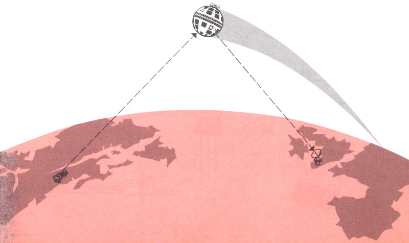
Microwaves sent via an orbiting satellite can travel vast distances
As long ago as 1945, Arthur C. Clarke, an English writer and scientist, proposed that a man-made satellite orbiting in space might be used to relay signals in this way. In 1945, of course, the very idea of getting a satellite out into space seemed utterly fantastic, and satellite communications could only be classified as science fiction. Ten years later, although Sputnik I had not yet been launched, artificial satellites were close to reality. At that time, John R. Pierce of Bell Telephone Laboratories made 14 the first serious study of what would have to be done to build a working satellite communication system—assuming it ever became possible to put satellites into orbit. And Bell Laboratories has been interested in satellite communications ever since.
With the first launching of a satellite into orbit by the Soviet Union in 1957, the real development work on satellite communications began. By 1960 Project Echo had proved that signals could be reflected off a man-made satellite and received several thousand miles away. And, in 1962, Project Telstar demonstrated to the whole world that an active repeater satellite could send telephone calls, data, and television across the ocean.
Bringing satellite communications almost to reality has required more than putting a man-made satellite into orbit around the earth. Just as important have been the invention and development of many remarkable new devices: the transistor, the solar cell, the traveling wave tube, the horn-reflector antenna, the waveguide, the solid-state maser, and the electronic computer—to mention only some of the more important. Without them it would still be impossible to find a tiny speeding object miles out in space, send signals to it, amplify them billions of times, and then return them to distant points on the earth.
Some of the new devices that help make satellite communications possible
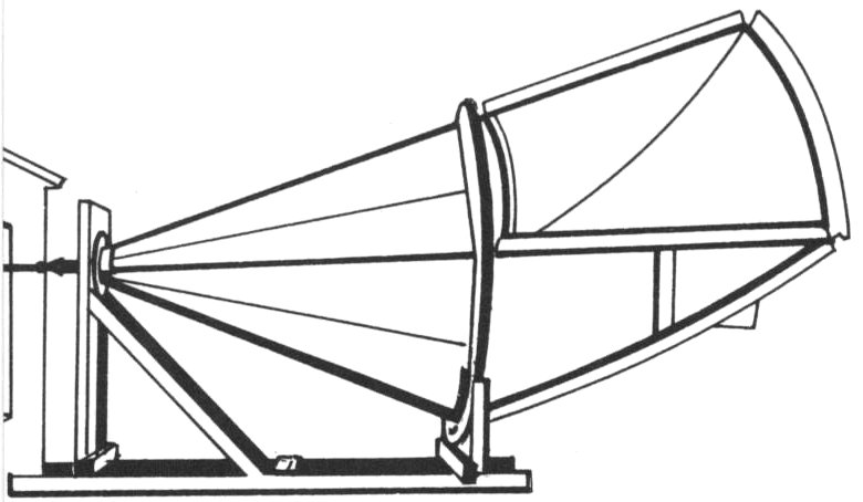
horn-reflector antenna
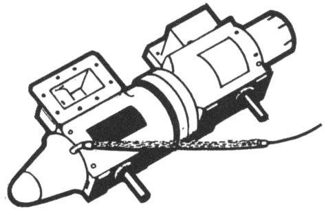
traveling-wave tube
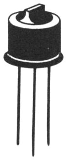
transistor
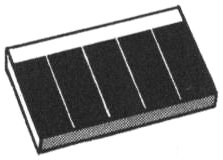
solar cell

solid-state maser
When you look back at it, we have seen remarkable progress in satellite communications—and work is still continuing at a fast pace. Some of the milestones have been these:
OCTOBER 1945 Arthur C. Clarke publishes “Extra-Terrestrial Relays—Can Rocket Stations Give World-Wide Radio Coverage?” in Wireless World, suggesting the use of satellites for communications.
JANUARY 11, 1946 Project Diana of the U. S. Army Signal Corps bounces microwave radar signals off the moon and back to the earth, proving that relatively low power can transmit signals over very long distances.
APRIL 1955 John R. Pierce publishes “Orbital Radio Relays” in Jet Propulsion, pointing out the requirements for a satellite communications system.
JULY 29, 1958 Congress passes the National Aeronautics and Space Act, setting up the National Aeronautics and Space Administration (NASA), with satellite communications experimentation as one of its interests.
DECEMBER 18, 1958 Score, the first communications satellite, is launched by the U. S. Air Force. It is equipped with tape recorder units that transmit prerecorded messages back to the earth upon receipt of signals. On December 19 a Christmas greeting to the world recorded by President Eisenhower—the first message from a satellite to the earth—is transmitted. Score continues to transmit for 12 days before its batteries become too weak for further use.
NOVEMBER 23, 1959 Live voice transmission is accomplished from Bell Telephone Laboratories in Holmdel, New Jersey, via the moon to Jet Propulsion 16 Laboratories in Goldstone, California. This is the first of 17 tests in Project Moonbounce, all using the moon as a reflector.
JULY 8, 1960 The Bell System proposes to the Federal Communications Commission a detailed plan for a world-wide communications system using active repeater satellites to provide telephone circuits and facilities for transmitting television to various parts of the world.
AUGUST 12, 1960 Echo I is launched into orbit by NASA. Project Echo carries on a large number of communications experiments and, most important, proves that it is practical to use a man-made satellite to reflect two-way telephone conversations across the United States. Echo also dramatizes the possibilities of satellites for communications. Since it is a 100-foot inflated balloon made from aluminum-coated Mylar, it is large enough to be seen by the naked eye. People throughout the world see Echo I sail on schedule across the sky in its 1000-mile-high circular orbit. Three years later, although it is now wrinkled and deflated, the balloon is still in orbit.

Project Echo provided valuable data for future work in satellite communications. It demonstrated that a passive satellite—that is, one that simply reflects the microwave signals it receives from an earth station back to another point—would work. Two-way conversations of good quality were sent between the Bell Laboratories Holmdel station and Jet Propulsion Laboratories in Goldstone, and successful transmission was made to other points in the United States and Europe. A scaled-up horn-reflector antenna proved itself. A method of receiving microwave signals that had been little used until then, known as frequency modulation with feedback (FMFB), performed very well. New types of low-noise amplifiers using solid-state masers gave excellent results. And tracking of the satellite by electronic computers, by radar, and by telescope proved to be extremely reliable.
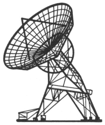
OCTOBER 4, 1960 Courier I-B is launched by the Army Signal Corps into a 500- to 650-mile-high orbit. A sphere weighing 500 pounds and measuring 51 inches in diameter, the Courier satellite is powered by 20,000 solar cells and contains four receivers, four transmitters, and five tape recorders. It is designed to demonstrate the possibility of using active repeaters for delayed transmission of messages. Signals are received, stored on the tapes, and then retransmitted back to earth when the satellite has moved on. After 18 days in orbit, technical difficulties ended Courier’s ability to send signals, but it received and retransmitted 118 million words during its active life.
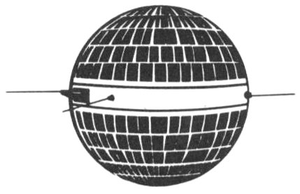
JANUARY 19, 1961 The American Telephone and Telegraph Company is authorized by the Federal Communications Commission to establish an experimental satellite communications link across the Atlantic. Two 170-pound satellites are to be launched by NASA but will be designed, built, and paid for by AT&T. This project is later given the name “Telstar.”
MAY 18, 1961 NASA selects the Radio Corporation of America to design and build the Relay satellite, which will be used to test the feasibility of transoceanic telephone, telegraph, and television communications.
AUGUST 11, 1961 NASA awards the Hughes Aircraft Corporation a contract to build Syncom, an experimental active satellite to be placed into a 22,300-mile-high orbit that will be synchronous with the rotation of the earth. (See page 37 for definitions of various kinds of satellite orbits.)
DECEMBER 20, 1961 The United Nations adopts a resolution on the peaceful uses of outer space that includes a request for world cooperation in developing a system of communications satellites. Both the United States and the Soviet Union sign the resolution.
FEBRUARY 7, 1962 President Kennedy asked Congress to pass a bill setting up a corporation to operate a satellite communications system. The proposed corporation would be owned jointly by the public at large and the country’s communications common carriers.
JULY 10, 1962 Project Telstar is successful. For the first time, voice communications and live television are transmitted across the Atlantic via a man-made satellite that picks up signals sent from one continent, amplifies them, and retransmits them to another continent. (On pages 21 to 33 we talk at further length about Project Telstar.)
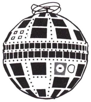
AUGUST 31, 1962 President Kennedy signs the Communications Satellite Act, establishing a private corporation under government regulation—the Communications Satellite Corporation—which will plan, own, and operate a commercial satellite communications system.
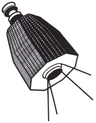
DECEMBER 13, 1962 Relay I is launched by NASA. Similar in many ways to the Telstar satellite, it is an active repeater device that picks up telephone, television, and other electronic signals and retransmits them to a distant point. Relay also provides the first satellite communications link between North and South America. The satellite is a tapered cylinder 33 inches long weighing 172 pounds. A mast-like antenna at one end is used to receive and transmit a single television broadcast or 12 simultaneous two-way telephone conversations. Four whip antennas at the other end of the cylinder handle control, tracking, and telemetry—turning experiments on and off and sending information on the behavior of its components and on the amount of radiation it encounters in space. Relay is powered by 19 nickel-cadmium storage batteries that are charged by more than 8,000 solar cells mounted on its eight sides. It contains two identical receiving, amplifying, and transmitting systems called transponders, each with an output of 10 watts.
Relay I is traveling in an orbit that ranges from 820 to 4,612 miles high, and circles the earth about every 185 minutes. Soon after it is launched, Relay’s telemetry reports trouble in the voltage regulator of one of the transponders, which causes excessive power drain. On January 3, 1963, the alternate transponder is switched on, and a successful series of tests—including live television broadcasts between the United States and Europe—begins.
JANUARY 4, 1963 The Telstar I satellite, which for almost two months could not be turned on to transmit communications signals, is reactivated by Bell Laboratories engineers. (The story of this ingenious electronic detective work is told in detail on pages 78 to 85.)
FEBRUARY 14, 1963 The first Syncom satellite is launched by NASA, but its communications systems do not operate. It is the first satellite to try for a synchronous path, revolving around the earth once every 24 hours and thus appearing to hover continuously over the same longitude. Syncom is a short cylinder 28 inches in diameter and 15½ inches long, and weighs 86 pounds. Like Telstar and Relay, it is powered by a combination of solar cells and nickel-cadmium batteries, but it is designed to handle only one two-way telephone conversation and cannot transmit television.
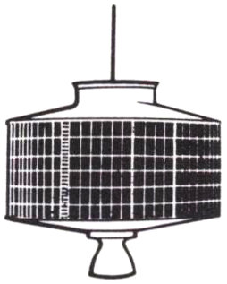
MAY 7,1963 The Telstar II satellite is launched for the Bell System by NASA. (See page 31.)
As this is written (June 1963), second Relay and Syncom launchings are in the offing. And there are plans for more experimentation with passive satellites, including a new, more nearly rigid Echo balloon.
Further in the future, studies are going on of a proposed Intermediate Altitude Communications Satellite for military use in the 6,000- to 10,000-mile-high range (beyond that of Telstar and Relay) and Advanced Syncom, a synchronous satellite of increased capacity. Work is also continuing to acquire new technical knowledge that will be needed in the future—such as various methods of keeping satellites stabilized in space and new ways of supplying power, including improved solar cells and the use of radioisotopes.
The ultimate goal, of course, is a working commercial communications satellite system. Exactly when this will be a reality—and what form it will take—are questions whose answers still lie ahead of us.
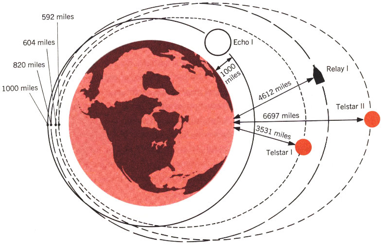
The orbits of four communications satellites vary in size and shape
| Echo I | 1000 miles | 1000 miles |
| Relay I | 4612 Miles | 820 miles |
| Telstar I | 3531 miles | 592 miles |
| Telstar II | 6697 miles | 604 miles |
In this section we will go into some detail about Project Telstar. We do this because much of what we learned from this project applies to the general field of satellite communications. The problems that were faced and solved are typical of the challenges that working engineers and scientists must meet today. And there is, of course, another reason to put this much emphasis on Telstar: The six case histories in Part II of our book were written by men who were involved with that project. Before reading their accounts it will be helpful for you to have some background information about it.
Even its most enthusiastic planners at Bell Telephone Laboratories never expected the sensation that Telstar caused. Although it was a deadly serious venture—one of the steps along the way toward putting together a workable satellite communications system—its success made it the inspiration, among other things, of cartoons, jokes, and a couple of popular songs. “Telstar” soon became a name recognized around the entire globe. Stories about Project Telstar appeared in newspapers in almost every language, in children’s books, in women’s fashion magazines.

On July 10 and 11, 1962, people on two continents saw these scenes on television at the same time, with the aid of the Telstar I satellite
What caused all this stir in the summer and fall of 1962? The answer—now that we look back on it—seems rather clear: For the first time, the whole world discovered that satellite communications was really possible—that peoples separated by oceans could now be united by live television. Space had become an adventure, not just for lonely astronauts, but for everyone right in his living room.
Project Telstar, of course, had more serious objectives:
To do its principal job—communications—the Telstar I satellite had to receive a signal from a ground station, amplify it, and then retransmit it on a different frequency back to other points on the earth. This signal had to be strong enough and good enough to be received and understood on the ground.
To do its secondary job—measure radiation and other conditions in space—the satellite had to be equipped with special testing devices and had to have a means of reporting facts about the environment it encountered in space and the effects of radiation on solar cells and transistors.
To let us know how well its equipment was working, the satellite had to record and transmit a large number of measurements—including such things as the temperature and pressure inside the satellite, its orientation with respect to the sun, the current and voltage in various parts of its electronic circuitry. Sending these measurements back to a ground station is called telemetry.
To help with tracking, the satellite had to have a continuous radio beacon signal that could be easily picked up on earth.
Finally, the satellite had to be able to control its equipment by means of signals from the ground. To keep the solar power plant from being overloaded, there had to be some way of “commanding” the satellite to turn itself on or off. As you will read later, this was the one part of the satellite that caused us the most headaches once Telstar I got into orbit.
Telstar’s outer appearance is very familiar by now: a 34½-inch sphere with 72 flat facets, a double row of rectangular openings circling its center, and a short, oddly twisted antenna on one end. Of the 72 facets, 60 are used for the solar cells that are the satellite’s main power source. When Telstar is in sunlight, these cells convert solar energy into electrical power; at full capacity the 3600 solar cells will supply about 15 watts. As time goes by, this power slowly diminishes as the cells are gradually damaged by such hazards of space as radiation particles and micrometeorites. To reduce this damage, the satellite’s cells are covered with a thin layer of man-made sapphire.
Two bands of rectangular openings go around the center of the satellite. The smaller cavities, of which there are 72, are receiving antennas; the 48 larger ones are transmitting antennas. This arrangement allows the antennas to transmit and receive equally well in all directions—except directly along the satellite’s poles.
At one end of the satellite is an entirely separate receiving and transmitting antenna that takes care of all the signals needed for Telstar’s command, tracking and telemetry. The antenna is composed of four metal loops joined in the shape of a helix. It receives the important command signals from the ground that give orders to the satellite’s equipment. It sends reports back to the ground from the special radiation measuring devices and other sensors aboard the satellite, and it also transmits the continuous 136-megacycle radio beacon that can be picked up by ground equipment searching for Telstar.
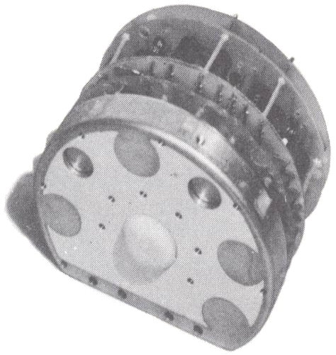
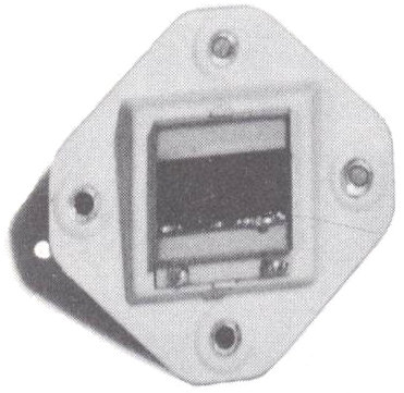
Six of the satellite’s flat facets are used for special measuring devices. Two different radiation studies are made: finding out how much damage will be done to solar cells and transistors, and determining how many actual energetic particles—protons and electrons—are present in the part of space that Telstar passes through. These different jobs are done by special devices on various facets. One, for example, consists of seven identical silicon transistors, six having different thicknesses of shielding and one being left unshielded—the amount of damage done to each is recorded and reported back to earth. Devices on another facet measure the radiation damage to solar cells protected by various thicknesses of sapphire. For the second radiation experiment—particle counting—four different types of silicon diodes are used as particle detectors. These measure the energy deposited both by protons of three energy levels and by electrons as the satellite passes through belts of natural and man-produced radiation in space.
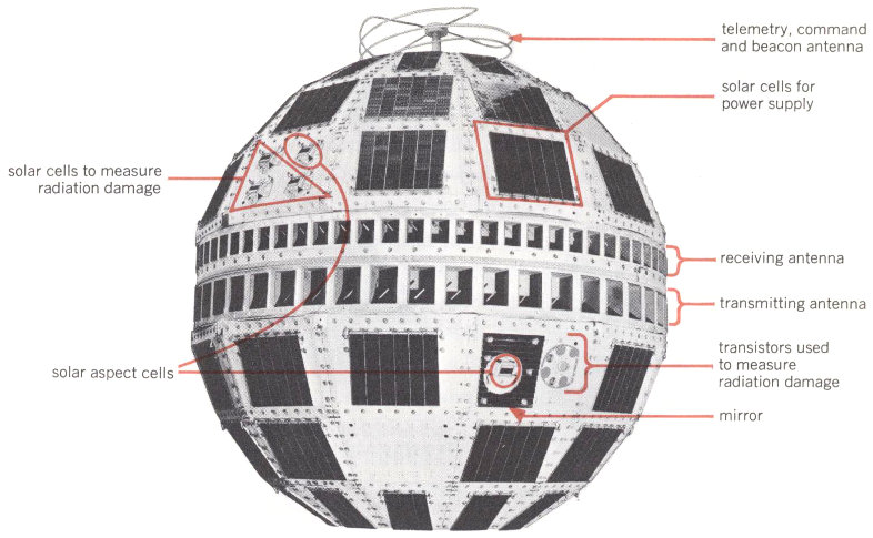
The Telstar I satellite—outside
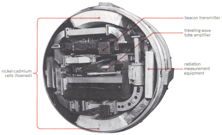
The Telstar I satellite—inside (looking at the electronics canister from the top down)
Measuring devices mounted on the surface of the Telstar I satellite
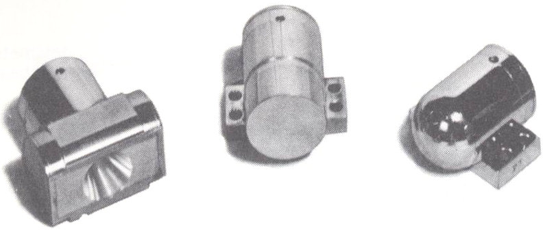
particle detectors used to count protons
transistors used to measure radiation damage
solar cells used to measure radiation damage and as solar aspect indicators
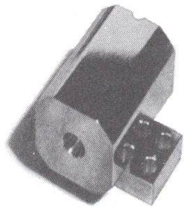
particle detector used to count electrons
There are two other special devices: Six single solar cells are spaced at regular intervals around the satellite; these “solar aspect” indicators report the quantity of sunlight hitting them—and thus tell the direction in which the satellite is pointing. Three highly polished metal mirrors are also placed on Telstar; flashes of sunlight reflected from them can be seen in a telescope. To give a precise indication of the satellite’s position, the data obtained from both the solar aspect cells and from the flashes off the mirrors are combined.
Within the white aluminum-oxide outer shell of the satellite is crammed a complicated array of electronic equipment. Surprisingly, most of this gear has to do not with Telstar’s prime function—communications—but with its command and telemetry systems. The reason is that the satellite is an experimental device, not just a spectacular way to relay television programs. Altogether, the satellite’s various electronic circuits contain more than a thousand transistors and almost 1500 semiconductor diodes, plus a single electron tube—a traveling-wave tube used in the communications amplifier.
The satellite itself has a magnesium frame that is covered with aluminum panels. All its electronic components are inside a aluminum canister, 20 inches in diameter, attached to the interior frame by special nylon lacings that reduced vibration inside the canister during launch. When all the components and subassemblies had been carefully put in place and thoroughly tested, the canister was filled with a liquid foam called polyurethane. This material hardens into a very light and rigid solid, completely enveloping the equipment and protecting it from damage and vibration. After the canister was solidly foamed, metal domes were welded onto the ends, and it was enclosed in a many-layered blanket of aluminum-coated Mylar (the same material used in the Echo balloon). To keep its temperature properly controlled, shutters on the canister’s two ends are operated by bellows.
The satellite power system includes more than just solar cells. When operating at full capacity, the satellite’s equipment needs more energy than the 3600 solar cells can provide at one time. So Telstar also uses a storage battery made up of 19 rechargeable nickel-cadmium cells designed for this special purpose. These ensure that the satellite has a continuous and sufficient supply of power, even when all equipment is in operation or when the satellite is passing through the earth’s shadow.
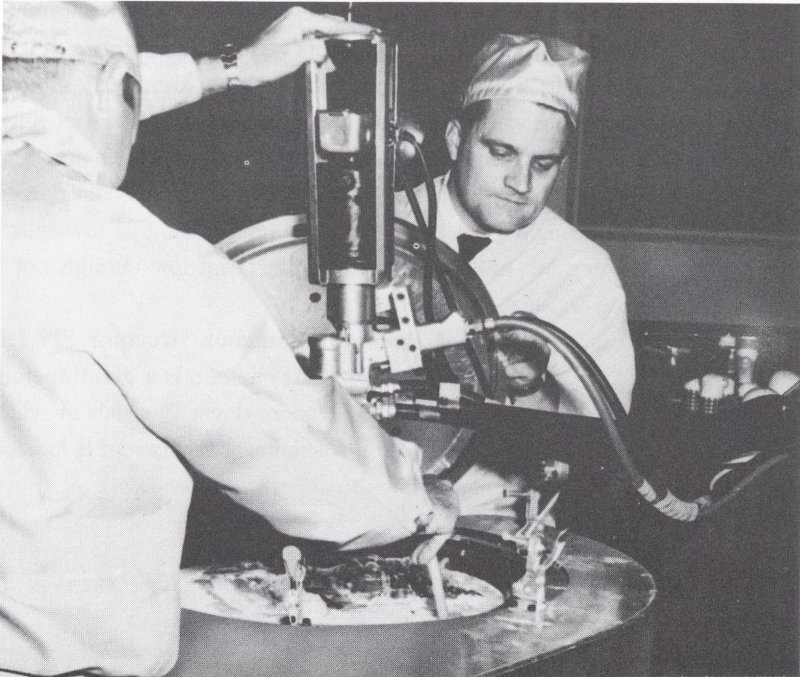
After all electrical tests had been made on the satellite’s components, the electronics canister was filled with liquid polyurethane foam, using this specially developed foam machine
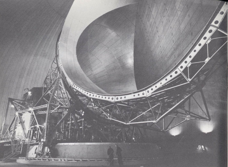
The giant horn antenna at Andover, Maine
Project Telstar is actually an extension into space of microwave communications methods that have been thoroughly proved on the ground. For Project Echo and other early experiments in satellite communications, Bell Laboratories built a large antenna of the type known as a horn-reflector in Holmdel, New Jersey. For Project Telstar, a similar but much larger antenna was designed. It was located in a relatively isolated spot at Andover, in the western part of Maine, where it would be close to Europe. The site is nicely protected by a surrounding ring of low hills—high enough to keep out interfering radio signals, but low enough not to block the satellite when it is near the horizon.
The giant Andover horn is a steel and aluminum structure 177 feet long and 94 feet high that weighs 380 tons. At one end is a giant opening of 3600 square feet; from there the horn tapers down to a cab in which the very sensitive receiver and powerful transmitting equipment is located. The entire antenna—horn, cab, and supporting framework—moves 29 smoothly on tracks that allow it to rotate in a 360-degree circle around its vertical axis (changing azimuth). It also can swing about its horizontal axis from the horizon up to the zenith (changing elevation). Despite its size, the antenna can revolve steadily and precisely in a complete circle in just four minutes.
Signals are beamed to the satellite on a frequency of 6390 megacycles, using modified Bell System microwave equipment and a special traveling-wave tube with an output of 2 kilowatts. Signals come back on a 4170-megacycle frequency at a much lower power level—as small as a trillionth of a watt. They are amplified by a ruby crystal maser that operates at the temperature of liquid helium—just a few degrees above absolute zero. The whole antenna structure and its associated equipment are enclosed in a huge “radome”—a bubble made from Dacron and synthetic rubber only a sixteenth of an inch thick but measuring 210 feet in diameter and 160 feet high. It is one of the largest air-supported structures ever erected.
The Andover ground station includes a lot more equipment—most of it having to do with tracking the satellite, computing its orbits, sending and receiving command and telemetry signals, and interconnecting the satellite with regular telephone and television land links. Most of this is located in a control building about a quarter mile from the giant radome.
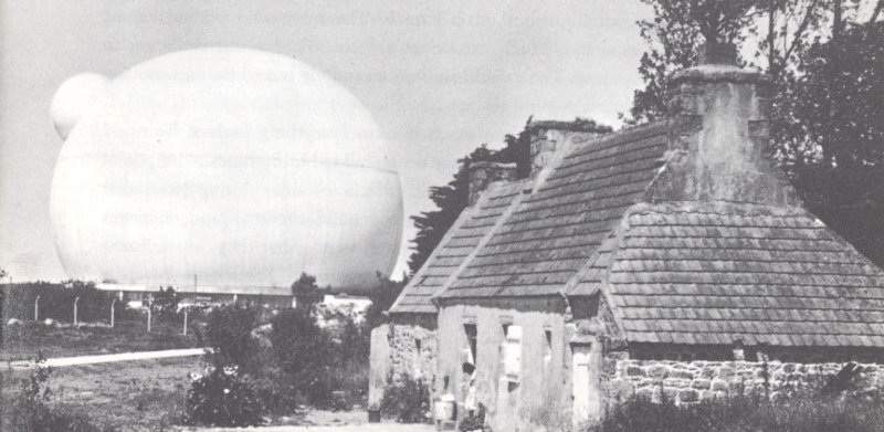
The French radome looms over the Brittany countryside
A ground station very similar to the Andover installation has been built by the French National Center of Telecommunications Studies at Pleumeur-Bodou in Brittany. The British General Post Office has established a station at Goonhilly Downs in Cornwall, England, which uses a 30 large, deep parabolic dish rather than a horn-reflector antenna. Both British and French stations participated in the first Telstar experiments. Satellite communications ground stations also have been set up in Fucino, Italy, and near Rio de Janeiro, Brazil, and others are under construction in West Germany and Japan.
At 4:35 a.m. (Eastern Daylight Time) on July 10, 1962, a Thor-Delta rocket launched Telstar I into its orbit, almost exactly according to plan, from the National Aeronautics and Space Administration’s Cape Canaveral base. On Telstar’s sixth orbit around the earth—at 7:26 p.m.—the first transmission to and from the satellite took place. During this pass telephone calls, television, and photos were transmitted between Andover and Holmdel. Some of these signals were also picked up in Europe. On the next day, a taped television program was sent from France to the United States, and a live program came from England via Telstar. During the next four months, more than 400 transmissions were handled by Telstar—including 50 television demonstrations (both black-and-white and color), the sending of telephone calls and data in both directions, and the relaying of facsimile and telephotos.
In addition, the satellite performed more than 300 valuable technical tests. Almost all of them showed remarkably successful results. Radio transmission was as good as was expected. Telstar’s communications equipment worked exactly as it should, with no damage from the shock and vibration of the launch. Temperatures inside the satellite were kept under good control. The satellite was successfully stabilized—prevented from tumbling over and over—by being spun around its polar axis, with the spin rate gradually decreasing, as predicted, from its rate of 177.7 revolutions per minute just after launch. The solar cells worked almost exactly as expected. Much extremely valuable data about radiation in space was reported. The ground stations accurately traced the fast-moving satellite in almost routine fashion.
But it would be asking too much to have everything perfect. Telstar I unexpectedly met radiation in space estimated to be 100 times more potent than had been predicted. As a result, difficulties arose during November 1962 in some of the transistors in its command circuit—and on pages 78 to 85 we tell you what these problems were, how they were discovered, and what steps were taken to overcome them. Some time later the 31 satellite again failed to respond to commands from the ground, and on February 21, 1963, it went silent.
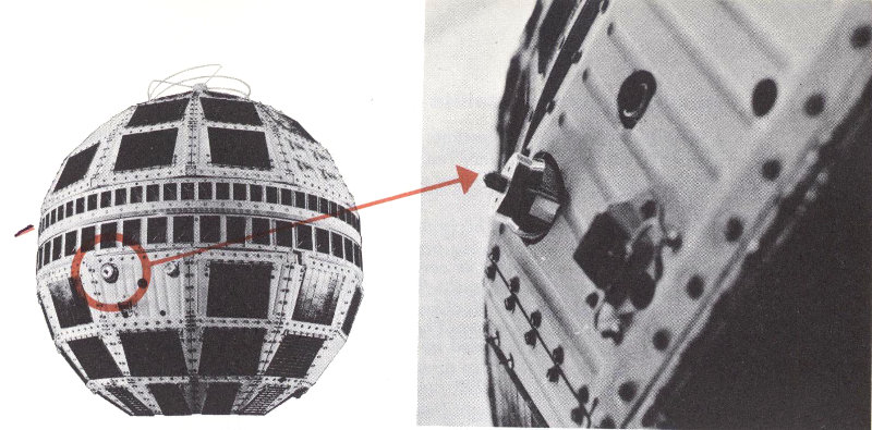
New gold-domed device on the Telstar II satellite can measure electrons in an energy range from 750 thousand to 2 million electron volts.
On May 7, 1963, the Telstar II satellite was launched into an elliptical orbit almost twice as large as that of Telstar I, ranging from an apogee of 6697 miles to a perigee of 604 miles. The new satellite circles the earth once every 225 minutes. The higher altitude provides Telstar II with longer periods when it is visible at both Andover and ground stations in Europe, and keeps it out of the high-radiation regions of space for a greater part of the time. The satellite itself is much the same as Telstar I, except for a few minor changes that make its weight 175 rather than 170 pounds. Its radiation measuring devices have a greater range of sensitivity, and there are six new measurements to be reported back to earth. Telemetry can now be sent on both the microwave beacon and, as before, on the 136-megacycle beacon. To help prevent the kind of damage that occurred in the transistors of Telstar I’s command decoders, Telstar II uses a different type of transistor, in which the gases have been removed from the cap enclosures that surround the transistor elements. A simplified method of operation for the giant Andover horn antenna is now in operation, with the autotrack alone being used for precise tracking and pointing. Telstar II’s first successful television transmission took place on May 7, and a new series of technical tests, radiation measurements, and experiments in transoceanic communications has begun.
A lot of facts and figures sometimes lead only to confusion, but these pages may help make things clearer. Here you can see—step by step—exactly what happens during a typical pass of the Telstar satellite over the Andover ground station:
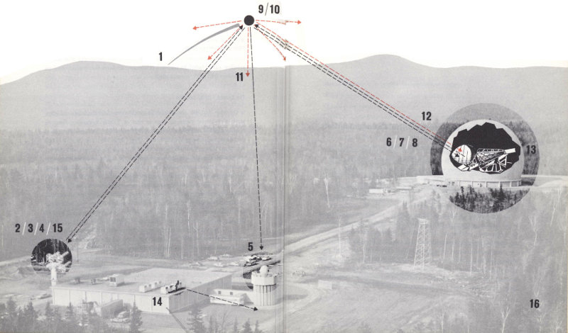
1 The satellite comes over the horizon.
2 The command tracker, knowing from computer data the satellite’s approximate location, begins to search for its continuous 136-megacycle beacon. A quad-helix antenna (four long spirals) tracks the satellite to an accuracy of one degree.
3 When the satellite is located, the command transmitter turns on the satellite’s transistor circuits and telemetry. The ground station then checks on the satellite’s operating condition, as reported by telemetry.
4 The command transmitter then turns on the satellite’s traveling-wave tube, which starts the transmission of a 4080-megacycle beacon signal.
5 The precision tracker—an eight-foot parabolic dish (known as a Cassegrainian antenna) mounted on a pylon—locates this beacon and tracks it to within one-fiftieth of a degree.
6 The horn antenna’s autotrack mechanism, which is pointed by both the precision tracker and data from magnetic tapes, locates the satellite’s beacon signal.
337 Now the horn antenna locks onto the satellite, with the autotrack continuing to make fine adjustments in pointing the horn.
8 The equipment is now ready for communications signals to be sent from the two-kilowatt ground transmitter to the satellite.
9 The satellite receives the signals and converts them down to a frequency of 90 megacycles; they are amplified in transistor circuits and converted up to a new frequency of 4170 megacycles.
10 The signals are amplified again by the traveling-wave tube—for a total amplification of as much as ten billion times—to get a radiated power of 2¼ watts.
11 The 4170-megacycle signals are now transmitted in all directions by the satellite’s equatorial antenna.
12 These signals can be picked up at Andover or at any other ground station equipped with a suitable antenna that is within line of sight of the satellite.
13 At Andover, the received signals are amplified by means of a solid-state maser and a frequency-modulation-with-feedback circuit.
14 They can now be relayed via regular land lines to their destination.
15 Near the end of a pass, the command tracker turns off the communications circuits and telemetry in the satellite.
16 The satellite drops below the horizon.
We hope the last few pages haven’t given you a wrong impression of satellite communications. It is easy to assume, when we list the orderly, step-by-step progress from purely theoretical ideas to a working satellite such as Telstar, that everything has gone like clockwork. That isn’t the case at all—and in the rest of this book we are going to show you why it isn’t. Many problems had to be solved; many scientific and technological advances had to be made.
We touched on a number of the problems of satellite communications in our detailed account of Project Telstar. Most of them are not confined to that project—they are the sorts of questions that any complex advance in satellite communications will run into. We will list some of the more important ones here. Then, in Part II, we will talk about some general methods of solving scientific and technological problems. All this is a rather roundabout—but necessary—way of leading up to our main interest: the accounts by six Bell Laboratories engineers and scientists of their work to solve some typical problems in satellite communications.
The many complications of satellite communications can be divided into several groups. First of all, there are the problems involved in fitting satellite communications into an already established world communications system. There are, next, many problems, both small and large, in designing the right kind of satellite. There are the problems of launching a satellite and getting it into the proper orbit. There are the problems in making sure it stays in the right orbit once it gets there. And, finally there are the problems in seeing that it continues to do its job reliably.
In these five categories there are a lot of specific questions that must be answered to plan a working satellite communications system. A list of some of them follows. We haven’t attempted to cover everything, but these should give you some idea of the tasks and questions involved in planning an immense project like this.
Circular Orbit—an orbit whose altitude from the earth remains constant; it makes a circle that has the center of the earth as a center.
Elliptical Orbit—an orbit whose altitude from the earth varies from one extreme to another; it makes an ellipse with the center of the earth as one focus. The orbit’s lowest altitude is called the perigee, its highest altitude is called the apogee.
Equatorial Orbit—an orbit in the plane of the earth’s equator.
Polar Orbit—an orbit in a plane formed by the North and South Poles.
Synchronous Orbit—an orbit whose period is 24 hours, the same as that of the earth revolving on its axis—so that the satellite’s and the earth’s angular velocities are the same. Although there are many possible kinds of synchronous orbits, each must have an average altitude above the earth’s surface of approximately 22,300 statute miles.
Stationary Orbit—an orbit that is circular, equatorial, and synchronous—so that the satellite will appear stationary from any point on the earth.
Inclined Synchronous Orbit—an orbit that is synchronous but not stationary, since it does not follow the plane of the equator. From a point on earth, it will appear to follow a figure eight pattern about a line of constant longitude.

The questions we listed in Part I cover a very broad area of science and technology. Their answers involve, more than anything else, physics, electrical engineering, and mechanical engineering. Some, however, also require that the men who work on them know chemistry, metallurgy, mathematics, and occasionally even biology, psychology, geography, and economics.
We obviously can’t show you how all the problems in Part I can be solved. Rather, we have picked six of them as examples. They are not necessarily the most important ones, but they seem to us to be typical of what engineers and scientists working in the satellite communications program actually have to do. These are the six problems we will be talking about at length:
As you can see, we have picked problems that offer a good deal of variety. Some of them have been satisfactorily solved; for others the solutions are not yet complete. Some deal with basic scientific research; others are much more concerned with the engineering applications of technical knowledge. Some were solved by careful, logical thinking; others were solved almost by accident. Some deal with a particular immediate task (in this case, Project Telstar); others are more concerned with general planning for satellite communications.
Despite these many important differences, there is one common thread running through the solving of all the problems we have chosen. The men who have been working on them had to know some basic principles of classical physics—principles that most of them first learned in their high school physics classes. You can’t, for example, calculate a satellite’s orbit without knowing Newton’s Laws of Motion. You can’t make optical measurements on a satellite without knowing the law of reflection of light. You can’t decide what color a satellite should be without knowing the law of heat exchange.
To emphasize the importance of a solid grounding in basic physical principles, we have tried to have our problems touch on most of the general 40 areas of physics: mechanics, heat, sound, light, electricity and magnetism, electronics, the properties of matter, atomic physics, physics of the solid state. But most of them, of course, are not limited to just one of these—they cross the lines of a number of areas. For instance, the problem of keeping solar cell power plants working in space involves laws of heat, mechanics, and atomic physics, as well as physics of the solid state. And, in studying the perception of time delay, we even branch out into experimental psychology.
When you start to solve a problem in science or engineering you can go about it in several ways. In some cases you have no choice: There may be only one practical method of doing the job. Other times, there may be several ways to attack the problem. You may try one, find it to be unfruitful, and then work on another approach. You will see both these methods of attack in the case histories we present in the next chapter.
Here are some of the techniques of scientific problem solving that we will be discussing:
Franz T. Geyling
Mechanics Specialist—Head, Analytic and Aerospace Mechanics Department
Before you can do anything with a communications satellite you have to know where it is at every instant of its motion around the earth. In other words, you need to know its orbit quite accurately. When you know this, you can predict when a particular station on the ground will be able to see the satellite and communicate with it. You also can tell when two or more stations can see the satellite simultaneously and communicate with each other. And you can estimate how many satellites will be needed to provide a group of ground stations with enough working time to maintain a communications service. This last, after all, is the ultimate goal of all our efforts in the communications satellite field.
In determining a satellite’s orbit, we find that we must do three things:
In the case of the Echo I satellite (see page 16), we engaged in the first and third of these activities. We had many chances to follow the satellite with our radars, and we could speculate how its orbit was changing through the months. In the case of the Telstar I satellite, we engaged in all three kinds of activity. We shall take a look at these problems in the sequence in which we came across them, for both the Echo and Telstar satellites.
We collect on the ground most of the information to calculate a satellite’s orbit, using optical instruments or radar equipment. Following a satellite through the sky is called tracking; in the early days after the first Sputniks, some of this tracking was done with the naked eye or with very simple telescopes by the Moonwatch teams. Many of you may have observed Echo I on a clear night without any kind of instrument.
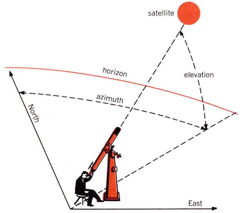
Figure 1
If we use a telescope, we note the time of the observation and we usually take a photograph of the satellite. We locate the satellite in terms of the two angles shown in Figure 1. One of these is the elevation angle—the number of degrees a telescope must be tilted above the horizon to see the satellite. The second is the azimuth angle—the number of degrees between the plane in which we measure the elevation angle and the north direction. Of course, we can also point a radar antenna at the satellite in the same manner. The radar can receive a signal transmitted by the satellite, or else it can send a signal to the satellite and watch for the reflected waves that eventually return. In the latter case, the satellite must have sufficient surface area to produce an adequate reflected signal. These two kinds of precision tracking were both possible with Echo I. Radar can also do something that optical equipment usually can’t do: measure the distance out to the satellite.
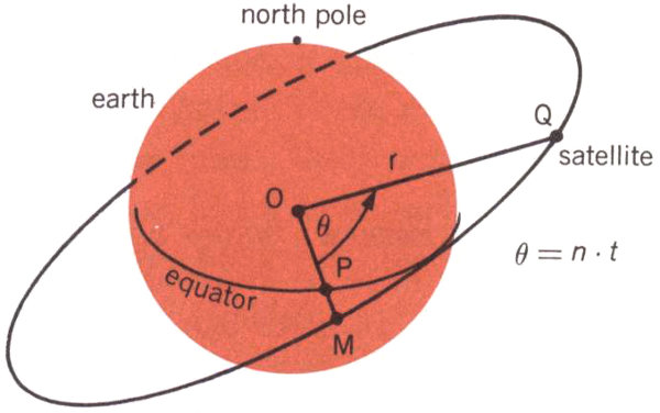
Figure 2
The Echo I satellite was launched into a circular orbit inclined at an angle to the plane of the earth’s equator. In Figure 2 this equatorial plane intersects the plane of the satellite orbit along the line OPM. The point O represents the center of the earth, the point M is on the satellite orbit, and the Point P is on the equator. At any instant, the satellite may be located in its orbit by the angle θ, which is measured between the line OM and the line OQ, where the point Q is the satellite’s location. If the satellite moves in a circular orbit, as in this case, the angle θ is proportional to time. That is, we can write θ = nt. We call n the angular speed of the satellite; one way of measuring this is in degrees per second.
Thus, the satellite is whirling at a constant speed about the earth like a stone tied to a string. Let us examine the physics of this situation a little more closely 43 with the help of Figure 3. If the satellite is moving with the velocity v, then we know that the centrifugal force acting on it is
| mv² |
| r |
where m is the mass of the satellite and r is its distance from the center of the earth. Obviously, no string ties the satellite to the earth, but the force of gravitational attraction between the earth and the satellite has the same effect. Newton’s law of mutual attraction tells us that this force is proportional to the product of the two masses divided by the square of the distance between their centers, or
| km |
| r² |
where k is a constant that essentially represents the mass of the earth.[1] Newton’s law also tells us that this force will be pointing toward the center of the earth if the earth is spherical. When the satellite is in circular motion, the centrifugal force and the gravitational force must balance each other. Hence we have
| km |
| r² |
| mv² |
| r |
and from this we can solve to find that the velocity of the satellite must be equal to
| k |
| r |
In the case of the Echo I satellite, which was designed to have a radial distance of r = 5000 miles, this velocity amounts to about 4.4 miles per second. The time for one revolution in orbit is obtained with the formula
| 2πr |
| v |
For the Echo satellite this time, T, turns out to be just about two hours.
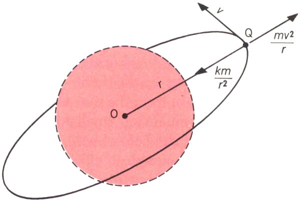
Figure 3
These basic physical principles of satellite motion can give us many useful answers. They tell us how fast we must move a precision tracker to follow the satellite through the sky, how much time a satellite will spend above the horizon, and how long will be the time from one chance of seeing it to the next. However, in the Echo project we were not merely concerned with planning our experiments from hour to hour; we also needed to know how the satellite would move for weeks and perhaps months in advance. When you study the motion of a satellite over such a length of time, you discover that its circular orbit will not remain the same as it was at launch. This fact had been observed on other satellites and was to be expected also with Echo.
In everything we have said so far it was assumed that the earth was a perfect sphere, which is the way a geographer’s globe presents it to us. In reality, the earth is somewhat flattened, with its diameter from the north pole to the south pole being somewhat shorter than its diameter at the equator. One way of looking at this is to visualize the earth as a sphere with some material added in the equatorial zone, which we may call equatorial bulge. This bulge causes Echo’s orbit to 44 have a slow “wobble” about the earth’s polar axis, somewhat like that of a spinning top.
Another force that makes the satellite’s orbit shift slightly is the faint pressure caused by the light from the sun. Although this pressure is much too small for us to perceive without the help of very delicate instruments, it is enough to affect a satellite, which has nothing to support it in space and is exposed to solar pressure for a very long time. Since the Echo balloon is a plastic sphere, 100 feet in diameter, that weighs only a little more than 100 pounds, the light rays striking its surface are enough to cause a second “wobble” effect. This wobble centers about the line from the earth to the sun. Light pressure also forces the orbit to go slightly out of round from a perfect circle, and other gradual effects on the satellite’s orbit are caused by the gravitational attraction of the moon and the sun.
All these disturbances are ever-present and act simultaneously, and a satellite’s total response to them is very complicated. Fortunately, however, most of the changes take place at a very slow and uniform rate, and we can predict them fairly accurately.
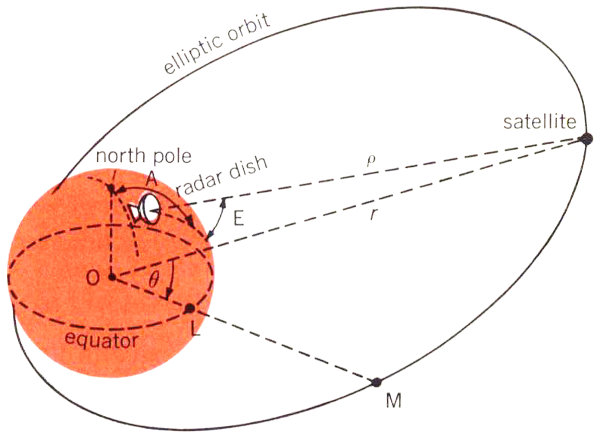
Figure 4
In Project Telstar we had to calculate the satellite’s orbit from observations made by our precision trackers. This introduced a few problems in addition to the ones we encountered with Project Echo. In the first place, the orbit of the Telstar satellite is a elongated ellipse, as indicated in Figure 4, rather than being almost circular, as in the case of Echo I. We mentioned earlier that a precision tracker can furnish data on a satellite’s elevation angle, E, and azimuth, A (see Figure 1). It can also give us a reading for ρ, the distance from the tracker to the satellite (Figure 4). If we know the position of the tracker on the earth, we can reduce the quantities A, E, and ρ to the angle θ and the distance r (measured from the center of the earth to the satellite). These two quantities locate the satellite in the plane of its orbit, but in order to describe its position completely we must also specify this orbital plane. In Figure 5 the orbital plane is shown as a shaded surface, with θ and r being the same as before. You will recall that the line OM represents the intersection between this plane and the equatorial plane; we call the angle i between the two planes the inclination of the orbit. Finally, we have the angle Ω between the line OM and some line OA to the point A, which we can choose as any convenient spot in the equatorial plane. Now we have specified the orbital plane completely. The point A can be found from day to day by fixing its position relative to a certain star in the sky.
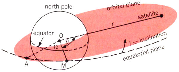
Figure 5
Figures 4 and 5 tell us something about the geometry of the satellite’s position in space, but for the complete story we must also give the time at which it can be found there. For this purpose, there are some astronomical laws that relate position on an elliptic orbit to time. Two of these are illustrated in Figure 6; in looking at this figure, you should imagine that you are standing off to one side of the orbital plane to get a good view of the entire orbit. The longest dimension of the ellipse, 2a, is called the major axis; this dimension is related to the satellite’s period—the time it takes to go once around the ellipse. More than three hundred years ago the astronomer Johannes Kepler observed that the period T, of an ellipse is
| a³ |
| k |
where k again was (using Newton’s work) essentially the mass of the earth.
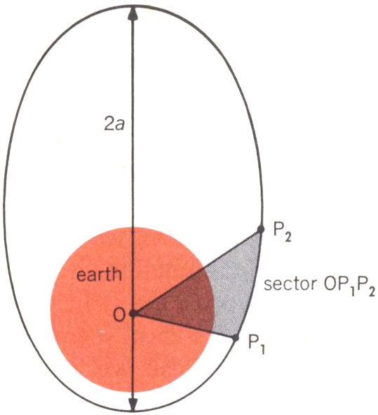
Figure 6
Instead of a complete revolution, we may only be concerned with part of one orbit. Let’s say that this part lies between the two positions P₁ and P₂ that the satellite occupies at the two times t₁ and t₂ (see Figure 6). Then another of Kepler’s laws says that the ratio between the time difference t₂ - t₁ and the period T equals the ratio between the sector of the ellipse OP₁P₂ and the area of the entire ellipse.
Now let us see how we can use the quantities r, θ, i, and Ω as well as Kepler’s two time laws to determine the motion of the satellite in space. Suppose that we have made observations of the Telstar at two times t₁ and t₂ and that we have measured its distance along lines ρ₁ and ρ₂ in Figure 7. In other words, we know that at these two times the satellite was at the points P₁ and P₂. Since three points determine a plane, we know in this case that P₁, P₂, and O define the satellite orbital plane. Knowing this, we can now calculate the angles θ₁ and θ₂, the distances r₁ and r₂, and the angles i and Ω. (The detailed formulas for this are derived from analytic geometry.)
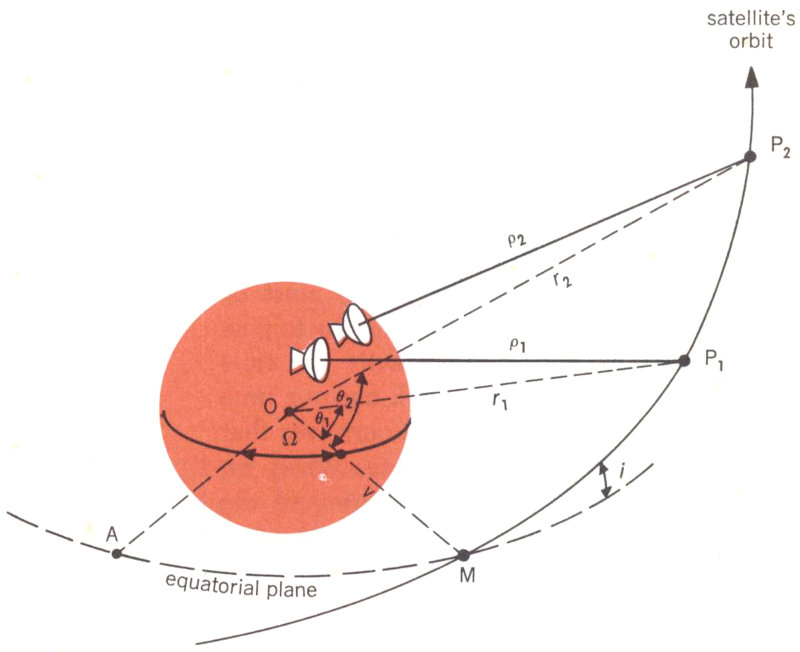
Figure 7
However, we still do not know the length and the width of the particular ellipse the satellite is following and how this orbit is oriented within the orbital plane. Let us imagine again that we can 46 stand off to one side of the orbit and take a good look at it; Figure 8 shows us what we would see. There are the two points P₂ and P₁ at which we have observed the satellite. We know the positions of these points relative to each other and in relation to the center of the earth, because we have already calculated r₂, r₁, θ₂, and θ₁, But any number of ellipses could be made to pass through these two points. Some might be very large, others might be so narrow that they would intersect the earth and thus be impossible. However, only one of these ellipses will satisfy the time difference that we observed between P₁ and P₂. In other words, the shape and period of this particular ellipse must be such that it will cause the satellite to pass through P₁ and P₂ in exactly the time interval t₂ - t₁. If we work out our time formulas, we will convince ourselves that there is only one such ellipse. When we have found it, we have determined the orbit of the Telstar satellite from the two observed positions and times.
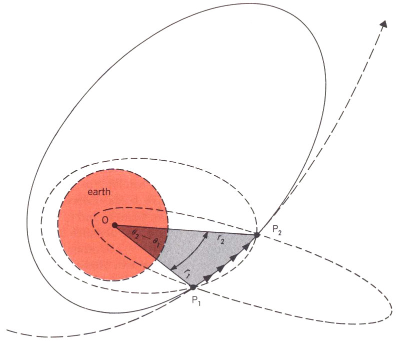
Figure 8
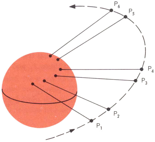
Figure 9
In principle then, we could keep track of the Telstar satellite by making a pair of observations P₁ and P₂, and then predicting ahead a short segment of an orbit that is the ellipse we have computed. After a while we must verify this ellipse with two more observations P₃ and P₄, predict ahead over another segment, and verify again with P₅ and P₆ (see Figure 9), The reason we have to keep taking new measurements is that the elliptic orbit does not remain the same. As we discussed in connection with Echo I, the orbital 47 plane will “wobble” about the earth because of the equatorial bulge. We also know that the orbit’s major axis will revolve within the orbital plane. As we have seen before, these effects are small and can be represented by appropriate mathematical formulas. If we calculate them, we will see the connection between one pair of observations and a later one, and eventually we can increase the time interval between successive pairs of observations. There are also mathematical formulas that we can use to predict the position of the satellite for many revolutions in its elliptic orbit.
In order to predict orbits successfully, we must also realize that the measurements we obtain from a precision tracker, such as the angles A and E and the distance ρ, are always subject to small inaccuracies. Thus it is not really possible to take just two measurements like P₁ and P₂ and determine a satisfactory orbit from them. In reality, our tracker takes many readings, and these are averaged to give adequate information about the orbit. Therefore, the picture we have in mind is not quite like Figure 7, but rather like Figure 10. Here the trackers have established a series of points that are somewhat scattered, and by taking averages we can calculate an orbit that passes through them in a smooth fashion.
The trackers we have mentioned so far have given us azimuth and elevation angles and also the distance to the satellite at every instant. Sometimes we must use simpler instruments that do not yield all this information. They might, for instance, only give us the two angles. The mathematics of calculating an orbit from such measurements is somewhat different, but the process is fundamentally the same as we have discussed here.
When you do these calculations for the Telstar satellite from one day to the next—and especially if you have more than one satellite to keep track of—the amount of work will become quite large. Nowadays our calculations are done for us on electronic computers, which both receive information from the tracking instruments automatically through Teletype or DataPhone channels and send back information concerning future positions of the satellite to the ground stations. There are still quite a few problems to be solved, and we are presently working on ways of making all this equipment perform the orbit predictions for the Telstar satellites automatically and efficiently.
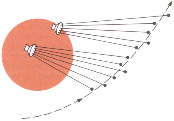
Figure 10
Franz T. Geyling was born in Tientsin, China, and received a B.S. in 1950, an M.S. in 1951, and a Ph.D. in 1954 from Stanford University. He joined Bell Telephone Laboratories in 1954, and has been engaged in celestial mechanics studies of rockets and satellites, as well as stress analysis of submarine cables.
Peter Hrycak
Mechanical Engineer—Member of Staff, Electron Device Laboratory
It is important for a satellite to stay at the proper temperature while it is orbiting in space. The instruments aboard it must continue to operate properly, and one way of insuring this is to keep them from being exposed to extreme heat or cold. We can, of course, regulate a satellite’s temperature somewhat with various kinds of devices, and we can see that one of its ends does not point towards the sun for too long. But in designing the Telstar satellite we also wanted to control temperature in an easier way: by covering the satellite’s external surface with material with the best properties—including the right color—for maintaining its over-all temperature at the right level.
A satellite’s temperature is determined by the balance between the heat that enters the satellite and the heat that leaves it. This means that we must be concerned with how heat is transferred. Heat can be transferred in three ways: by conduction, when two bodies are in direct contact and their molecules collide; by convection, which utilizes the movement of warm currents in a fluid; and by radiation, in which heat energy travels as electromagnetic waves at the speed of light. With a satellite, we are concerned only with the last of these, since the only way energy can be gained or lost in space is by radiation.
In the transfer of heat by radiation, the surface of the heated body—such as a satellite—is very important. All energy gained must be absorbed at the surface; all energy leaving must be emitted at the surface. So the physical properties of this surface control how energy is absorbed and how it is emitted. The origin of the radiant energy is vitally important; most surfaces, for instance, will behave differently when exposed to solar radiation from the sun’s temperature of 10,000° Fahrenheit than when exposed to radiation from nearby objects at room temperature.
The physical property of a material that controls the way it absorbs radiant energy is called its absorptivity, and the property that controls its emission of energy is its emissivity. For absorptivity we use the symbol α; for emissivity we use the symbol ε.
When radiant energy reaches a surface, only a certain part of it is absorbed; the rest is either reflected, just as light rays are reflected, or else passes right through it. The absorptivity, α, of a substance tells us what percentage of radiant energy it will absorb. A perfect absorber, or black body, would absorb all the radiant energy that reached it. If such an ideal substance existed (which it doesn’t) we would say it had an α of 1. The actual absorptivities of real substances are indicated by numbers between 0 and 1: The α of black velvet cloth, for example, is about 0.97; that of a polished silver mirror is about 0.08 for solar radiation (absorptivity for most polished metals for room temperature radiation is even lower).
We measure emissivity, ε, in very much the same way. A hypothetical black body would emit all the energy it possibly could and have an ε of 1; the emissivities of real substances are indicated by numbers between 0 and 1. For any given frequency (or color) of light, a substance’s absorptivity and emissivity are equal; however, the total spectrum of frequencies of the energy absorbed is usually different from that of the energy emitted.
The ratio between emissivity and absorptivity, α/ε, is very important, as we shall see later. If this ratio is greater than 1, it means that a substance absorbs heat faster than it emits it, and thus tends to become warmer. If the ratio is less than 1, the reverse is true—the surface emits radiant energy at a faster rate than it absorbs it, and tends to become cooler.
This is one of the fundamental relationships of modern physics:
It was discovered experimentally by Josef Stefan in 1879, and verified theoretically by Ludwig Boltzmann; it is known as the Stefan-Boltzmann Law. This formula tells us the amount of radiant energy, Qbody, 50 that will be emitted by a body having the surface area A when it is at the temperature T. Temperature, here, is measured in degrees Rankine (°R), or Fahrenheit temperature above absolute zero (to calculate degrees Rankine, add 460 to the temperature in degrees Fahrenheit). The expression εA is used to show that only a certain fraction of the energy that would leave a perfect black body of area A will actually leave a real body of the same size; the size of this fraction is determined by the body’s emissivity. The symbol σ is a quantity we call the Stefan-Boltzmann constant.
We can also calculate the heat from the sun that will be absorbed by a body. If we let S be the total amount of solar energy that would be absorbed by a perfect black body, αS will be the amount that is actually absorbed by a body with an absorptivity of α for solar radiation. If our body is a spherical satellite, the sun’s rays will only strike it from a single direction. Thus only an area equivalent to the sphere’s cross-section (largest inscribed circle) will receive energy at any one time. Since, as shown in the sketch, this area (a = πr²) is one-fourth that of the sphere’s total surface area (A = 4πr²), we know that the radiant energy from the sun that is absorbed will be
| A |
| 4 |
A man-made satellite’s position relative to the earth is very like that of the earth in relation to the sun; the earth, after all, is itself a satellite of the sun. And during most of its useful life a satellite will be in thermal equilibrium—it will be losing just as much heat energy by its own radiation into space as it will be gaining from other sources, primarily the sun. Since the total amount of energy it absorbs is equal to the amount of energy it emits, Qbody is equal to Qsun. This means that we have the equality
| A |
| 4 |
Now, if we solve this for temperature, we will get
| α |
| ε |
| S |
| 4σ |
| ¼ |
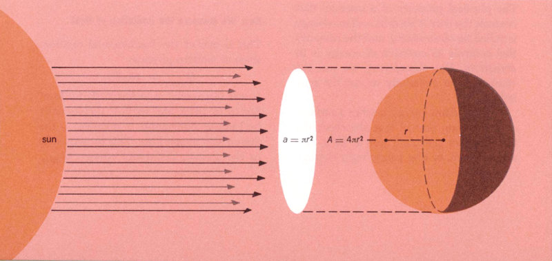
Although the total surface area, A, of a sphere is 4πr², light rays from the sun only strike half the surface at any one time. This area, a, is effectively equal to the sphere’s cross-section, πr².
This equation is well known in astronomy, and has been used for more than 80 years to calculate the temperatures of various 51 objects in the sky. Today, we still find it useful for measuring the surface temperatures of man-made satellites such as Telstar. Since both S and σ are known constants (in this case, we use the quantities S = 445 and σ = 0.173 × 10⁻⁸), you can see that temperature is dependent on the α/ε ratio.
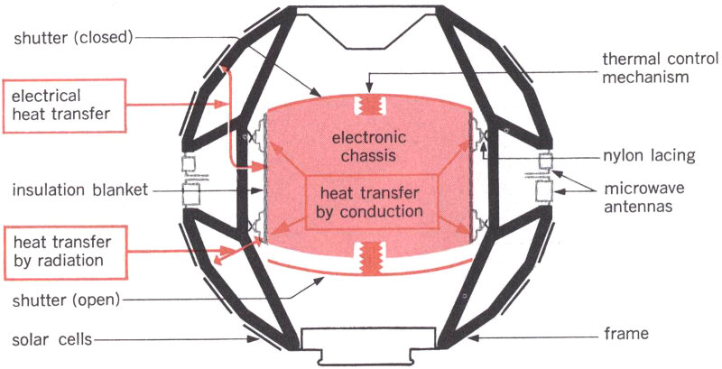
Cutaway view of the inside of the Telstar I satellite, showing the electronics canister covered with its protective blanket of many layers of Mylar. To control temperature, shutters automatically open all the way if the canister gets hotter than 80°F, close completely if it goes down to 50°F.
In designing the Telstar satellite, both its internal and external temperatures had to be controlled. The electronics canister inside the satellite operates best if it stays at approximately room temperature of 65 to 75°F. This much heat is supplied in the canister by dissipation of electrical energy from the solar cells. The container is well insulated to keep its temperature relatively stable, and it has shutters that open automatically if it begins to get overheated (see above). The operating characteristics of the solar cells on Telstar’s surface also had to be considered; they work better at rather cool temperatures. So we decided to keep the satellite’s skin at an average temperature of about 0°F, although temperatures actually will range quite a bit above and below the average as the satellite moves from sun to shadow.
Now, using this average temperature of 0°F (converted to 460°R) as T in our formula, we can solve for α/ε. We find that this gives us a ratio of approximately 0.7 for the satellite’s surface. However, this presents a problem. Almost 40 per cent of Telstar’s surface is taken up by its power plant of 3600 sapphire-covered solar cells. These cells, unfortunately, have a relatively high α/ε ratio—their α is 0.8 and their ε is 0.54, for an α/ε of 1.5. This means that the portion of the surface not used by either solar cells or antenna openings must, in order to give us an over-all average of about 0.7, have a very low α/ε ratio—less than 0.3.
To get this sort of ratio, we had to select carefully the material for the outer surface of the Telstar satellite. There were many kinds of surfaces that might have been used; they could have been metal or non-metal, rough or smooth, shiny or dull. And 52 they could have been any color from black to white. However, to get a 0.3 ratio we needed something with a relatively high emissivity for the low-frequency electromagnetic radiation that the satellite emits and a rather low absorptivity for the high-frequency radiation coming from the sun. High emissivity meant that we should use a nonmetal surface rather than polished metal, since the emissivity of nonmetals is quite high at the temperatures in which we were interested, while that of polished metals is relatively low. And, to get low absorptivity, we decided that the color of these surface areas should be very close to a pure white.
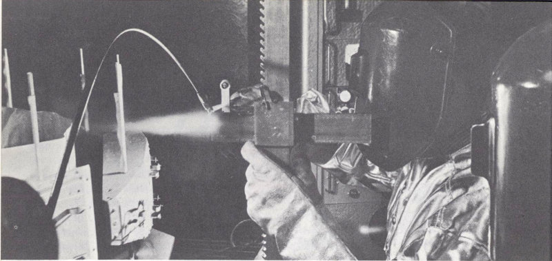
Partially molten aluminum oxide particles being sprayed onto aluminum outer surface panels.
There were several substances that met our requirements. After testing a number of them, we decided to use aluminum panels coated with a thin layer of aluminum oxide (Al₂O₃). This coating is very pure, hard, and stable, and we left it rough to minimize changes due to meteoroid abrasion. Its α/ε ratio is 0.24. The aluminum oxide coating can be applied by means of the plasma jet process—particles of aluminum oxide are heated to a partially molten state, mixed with gases, and then sprayed onto the cleaned, pre-coated aluminum panels (see illustration above).
Using this carefully selected outer surface has helped solve the temperature-control problem. Since Telstar has been in orbit its internal and skin temperatures have kept well within the ranges we wanted them to. Thus you can see how some basic formulas from classical physics helped us choose the right material for the satellite’s surface—and even what color it should be. The blue-and-white checkered appearance that Telstar I finally took on was no accident—it was the result of carefully combining various colors and materials in just the right amounts to obtain the temperature balance we needed.
Peter Hrycak was born in Przemysl, Western Ukraine, and received a B.S. in 1954, an M.S. in 1955, and a Ph.D. in 1960 from the University of Minnesota. He joined Bell Telephone Laboratories in 1960, and has worked on low temperature refrigeration problems and thermal design and thermal testing of the Telstar satellite.
Jeofry S. Courtney-Pratt
Physicist—Head, Mechanics Research Department
Since the first Telstar satellite went into orbit, we have tried to trace its path through space precisely. But we also have had to keep a constant check on the position, or attitude, that the satellite takes as it travels. We are particularly interested in the direction of the spin axis about which it revolves, and we also want to know its spin rate, which is the number revolutions the satellite makes each minute. Although these might seem relatively simple jobs, they actually turned out to be rather complicated. And only at virtually the last minute, just before the satellite’s design was finally set, did we think of a new way of using reflected flashes of sunlight to report on its spin axis and spin rate.
When the satellite was injected into its orbit, it was spin-stabilized to keep it from tumbling over and over, much as a rifle bullet is stabilized by being spun about its longitudinal axis. The Telstar satellite is roughly spherical, and it was designed to spin with the helical antenna end as its north pole and the antenna bands as its equator. On July 10, 1962, the satellite was given an initial spin of 177.7 revolutions a minute. As we expected, this rate is decreasing gradually; after two years it will only be spinning one tenth as fast.
The most important reason for keeping a close watch on the satellite’s spin axis is to make sure that microwave signals are sent and received steadily. It isn’t possible to build an antenna that radiates at exactly the same power in all directions. Telstar’s antennas work very well, but they operate better in the direction of the satellite’s equator than they do towards its poles. This means that if the spin axis is constantly changing transmission will fade in and out—even at times passing through “null” where no transmission at all is possible. No single fixed orientation is perfect for the spin axis, but we decided that the best average position would be to keep it always perpendicular to the plane of the earth’s orbit. We tried to make sure that the spin axis would not vary by more than five degrees from this direction at any time—although it probably could depart as much as 15 or 20 degrees without doing serious harm.
A second reason for being careful about the satellite’s spin axis is the problem of 54 heat balance. If one end of the satellite points constantly at the sun and the other end does not, the end near the sun will get much too hot and the other will get much too cold. Therefore, we tried to fix the spin axis so that it stayed perpendicular to a line drawn from the satellite to the sun.
We also wanted to get a continuing report on the effects of the magnetic field of the earth at high altitudes. We knew these would cause the spin axis to change with time, or precess, but we couldn’t be exactly sure what these changes would be.
Since the orientation of Telstar’s spin axis was so important we installed a torque coil in the satellite. This is a coil of wire in which, upon a signal from the ground, an electric current can be made to flow. The current produces a magnetic field that interacts with the earth’s magnetic field to change the position of the satellite’s spin axis. However, we could not be sure that this device would work properly—and this is another reason why we wanted to keep track of the exact position of the spin axis.
One of the devices built into Telstar is a set of six solar aspect cells spaced at regular intervals around the satellite. These give a fairly accurate indication of the angle between the spin axis of the satellite and a line joining the satellite and the sun. When sunlight strikes these solar cells, they produce electric currents, and the value of the current from each cell is sent back to the ground via telemetry. Three of the cells are in the satellite’s northern hemisphere; three are in the southern hemisphere. If Telstar’s north pole were pointing to the sun, for example, the three northern cells would record large, equal currents; those in the southern hemisphere would show zero current. But if the spin axis were perpendicular to the satellite-sun line (as we want it to be) all six cells would report equal, average-sized currents, which would fluctuate as the satellite spun around. The solar cells were carefully calibrated before Telstar was launched, and we estimate that they can tell us the angle between the satellite’s spin axis and the satellite-sun line to within one or two degrees.
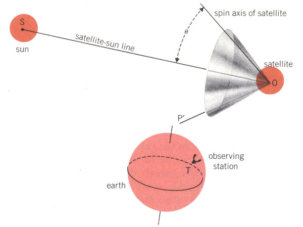
However, this one angle is not enough to locate the spin axis exactly. As you can see in Diagram 1, there are many possible positions for the spin axis OP that have the same angle θ with the satellite-sun line OS. These positions all would lie on the surface of an imaginary cone OPP′ that has OS as its axis and 2θ as its vertex angle. We need to have a second measurement to find a single position for the spin axis. As late as November 1961 we had not found a satisfactory way to make such a second measurement. Then Donald Gibble of Bell Telephone Laboratories suggested that we observe the reflections of sunlight from mirrors fitted onto the satellite[2].
Only when a satellite is in the right position can you see the reflection of sunlight from a plane surface on its body. Diagram 2 shows how flashes of reflected light are observed. The light of the sun, S, is reflected from a plane surface, R, on the satellite to our observing station, T, on the earth. If we imagine the line ORB drawn perpendicular to R, we know, from the law of reflection, that the angle of incidence, i, made by the sunlight to this line will be equal to the angle of reflection, i′, between the reflected light and 55 the same line. The law of reflection also tells us that the sun, the line ORB, and the observing station all must now lie in the same plane. And, since we can calculate where the satellite is in its orbit at this exact moment, we can locate line ORB. But what about the spin axis? We know where on the satellite our reflector R is located, so we know ahead of time what the angle θ′ between ORB and the spin axis, OP, will be. We call it the flash angle. Thus we can tell that the spin axis will be somewhere on the surface of an imaginary cone OPP″ that has ORB as its axis and 2θ′ as its vertex angle[3].
1.
Solar aspect cells on the satellite report via
telemetry the amount of sunlight they receive;
from these data we can calculate the angle θ
between the satellite’s spin axis, OP, and the
satellite-sun line, OS. This means that OP
can be anywhere on the surface of cone OPP′.
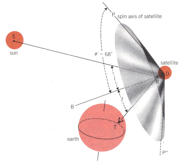
2.
When sunlight is reflected to observing station
T on the earth, we know that the angle
of incidence i must be equal to the angle of
reflection i′, and, if ORB is a line perpendicular
to the reflector R, we know that the
sun, the observer, and line ORB must all lie
in one plane. Since we also know the position
of the satellite in its orbit and the distance
from it to the earth, we can locate line ORB
precisely. The reflector R is set at an angle
θ′ of 68° from the spin axis OP. This tells us
that the spin axis must lie on the cone OPP″,
which is now precisely determined by its axis
ORB and its vertex angle 2θ′, equal to 136°.
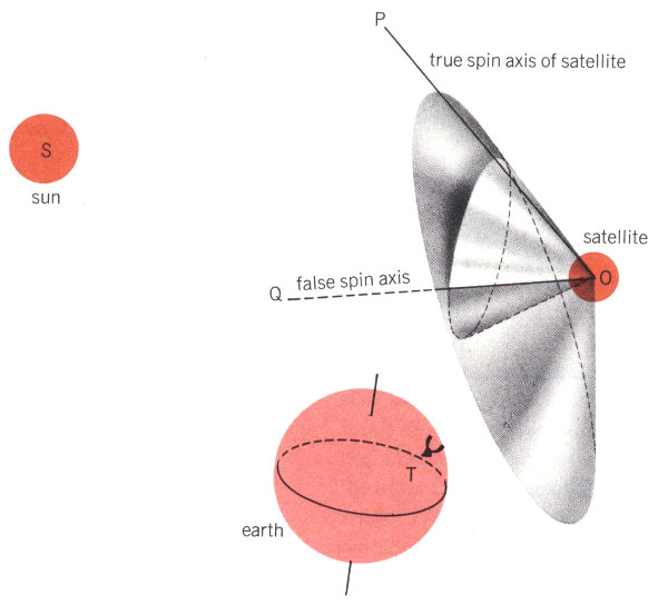
3.
Cones OPP′ and OPP″ intersect along the two lines OP and OQ, so these are the only possible
spin axis locations. From our general knowledge of the situation (or from any third measurement
of glint time), OQ can be ruled out, and we conclude that only OP can be the true spin axis.
In Diagram 3 we have combined our two measurements of the satellite’s spin axis. You can see that the two cones will intersect along two straight lines, OP and OQ; these are thus the only possible positions that will satisfy both our measurements. Actually, of course, only one of these lines is the true location of the spin axis. And it is usually obvious which one it is, when we consider all our other data about the satellite’s position.
Using this technique, if we measure the exact times when we see flashes of reflected sunlight from Telstar, we can combine that information with data from our six solar aspect cells and get a good plot of the position of the satellite’s spin axis.
In theory, this looked like a very promising idea. But finding a satisfactory way to put it into practice was something else again. Our first thought was simply to make use of the light reflected from the sapphire covers on the satellite’s solar cells. However, these covers have a low coefficient of reflection and do not form a completely flat surface. This means that the light reflected from them is very much reduced in intensity and spreads out too much to give us the precise readings we want. On the other hand, if we attached a plane mirror with a high reflection coefficient to the satellite, we thought we could 57 pick up the minute flashes of reflected light from a distance of as much as a few thousand miles. So we decided to press ahead with this scheme and install one or more reflectors on the satellite.
By the time we started work on the mirrors, the final design of Telstar I was almost complete; this meant that we had to squeeze our mirrors aboard it as best we could. The most stringent physical requirement in designing them was weight; they could not add more than half a pound to Telstar’s total load. Nor could they project more than one-eighth inch from the satellite’s surface, or they might interfere with the radiation pattern for the main antenna. We also decided to make the mirrors out of highly polished metal, since any other possible material might break too easily. And the mirrors had to be as flat as possible, so the beam of reflected sunlight would not diverge by more than one degree.
Thus we had to design mirrors that would be very thin, very shiny, very flat, very light, and almost unbreakable. After much experimenting, we solved this rather tricky problem. The mirrors we added onto Telstar I, as you can see in the illustration below, were machined from aluminum alloy sheet, carefully polished by hand with abrasive papers, and buffed on a cloth wheel. Finally, we evaporated a thin layer of pure aluminum onto their surfaces to improve their reflection coefficients and make them resistant to corrosion. The three mirrors were fastened to the surface of the satellite with small screws, which had to be tightened and shimmed very carefully so that the mirrors stayed as flat as possible.
As we mentioned above, the flash angle θ′ between the satellite’s spin axis and a line perpendicular to the mirror is very important in our calculations. We made detailed studies of the various flash angles that would be possible during the first 60 days after launch. We plotted the times when the satellite would be above the horizon while our Crawford’s Hill, New Jersey, observing station was in darkness, and we made allowance for satellite orbits that might deviate slightly from the planned one. These calculations told us that the best flash angle for the mirror would be 68 degrees—which is the angle made by the first facets above Telstar’s equatorial antenna band. So we located a flat mirror on one of these facets. Because one of the solar aspect cells was already installed in the center of this facet, we were forced to cut a circular hole out of the center of the mirror.
But we knew that one mirror could not do the whole job. After Telstar I had been in orbit more than 30 days, the 68-degree mirror would only be in position to give infrequent flashes, and one at about 95 degrees would be more useful. This presented two problems. First, no facet on the satellite makes a 95-degree angle with the spin axis. However, we could use one of the facets just below the equatorial antenna, which makes a 112-degree angle, and groove or facet the mirror so that its reflecting faces became narrow strips slanted 17 degrees away from the base at the angle of 95 degrees (112 - 17 = 95). Our second problem was space—since there was not enough room left on any of the 112-degree facets to mount a second large mirror, we substituted two smaller mirrors and mounted them 120 degrees apart. This arrangement lets us know from which mirror we see flashes—the plane mirror gives one flash for each revolution of the satellite; the faceted mirrors give two flashes for each revolution of the satellite.
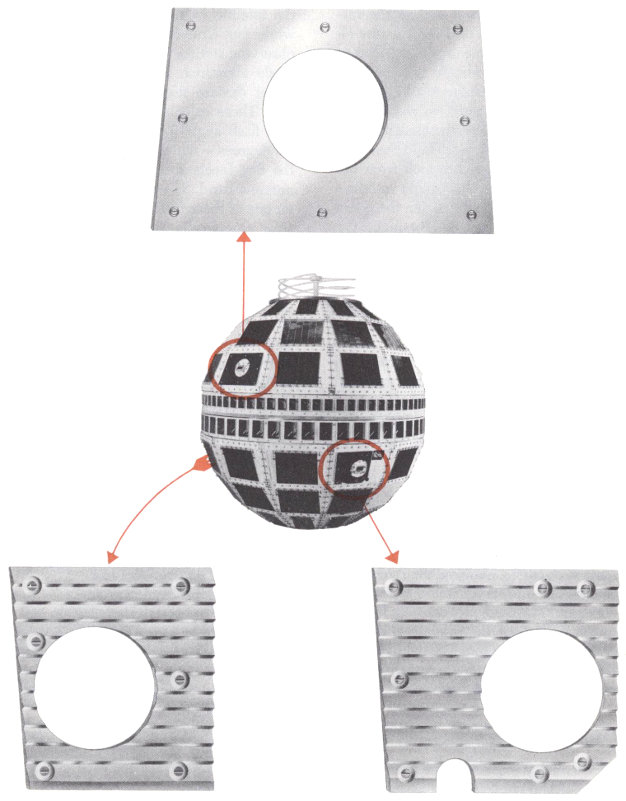
Sketches of three reflecting mirrors and their locations on the Telstar satellite. The upper plane mirror is set at 68° to the spin axis; the lower ones are faceted to give reflecting surfaces at 95°. Two of the satellite’s six solar aspect cells can be seen within the circular cut-outs in the mirrors.
Now we had finally found a satisfactory way to reflect a train of tiny flashes—much too faint to be seen by the naked eye—from Telstar as it passed across the sky during the night. But our main aim was to record the exact times when these flash bursts occurred. With this information, we could, using the method we described above, tell very accurately both the satellite’s spin axis and its rate of spin. We do not have space to describe the many problems that had to be solved in setting up the equipment to record the flashes. Let us merely outline the procedure that we finally devised:
1. To pick up the satellite’s flashes we use a 12-inch-aperture photoelectric telescope mounted on a radar trailer (shown in illustration below). It is pointed by means of prediction drive tapes produced by an electronic computer; these are based on data from previous passes.
2. On clear, dark nights when the satellite is at relatively short range, we can see it with an auxiliary finder telescope, and then adjust the large telescope precisely. Or, if the satellite’s high-frequency beacon has been turned on, the Holmdel microwave antenna can automatically point our large telescope.
3. When flashes of light are picked up by the telescope, they fall directly onto the cathode of a photomultiplier tube. They are then filtered out from the random light in the night sky and amplified.
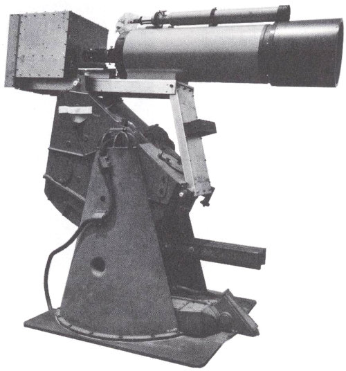
Twelve-inch telescope and electronics box mounted on a radar antenna pedestal at Crawford’s Hill. Three-inch sighting telescope mounted on top has since been replaced by six-inch telescope.
4. Rather than make a continuous recording of the output—one night this would have produced a record twelve miles long for us to pore over—we use an electronic trigger. This is the time base of an oscilloscope, whose sawtooth output is set in operation only if a signal of four volts or more is received (photo below).
5. A pen recorder makes a continuous line on a revolving drum, with a heated stylus connected to a galvanometer marking a permanent record on heat-sensitive paper. Any signal output from the oscilloscope is picked up by the galvanometer and causes the pen to make a sawtoothed mark; when the paper is unrolled from the drum, these marks are clearly visible as notches in a series of otherwise straight lines.
6. A synchronous timer marks the chart every ten seconds, and we are able to time individual pulses with a precision of one tenth of a second. Because the beginning and end of a train of pulses are not always distinct, we can only determine the center of a burst of flashes—which we use as our most important time indication—to within two seconds. However, this is accurate enough, for a change of only one degree in the orientation of the satellite’s spin axis would change the time of the flash burst center by about half a minute (see below).
7. We use a second oscilloscope to check on whether the signals we receive are genuine flashes or just accidental stray light. This oscilloscope has a long-persistence screen, which we use as a temporary memory. The pulses traced on its cathode ray tube are automatically photographed by a 35-mm camera while they persist on the screen. We can then examine the photograph to see if the pulses are genuine, which we ascertain from (a) their shape and size and (b) the intervals between successive pulses. Looking at the photographic record also confirms whether we are observing flashes from the 68° plane mirror or the 95° faceted mirrors. We can calculate the satellite’s spin rate by measuring the intervals between individual flashes.
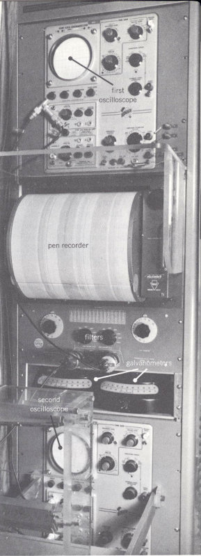
General view of amplifying, monitoring, and recording gear that picks up glints of sunlight at the Crawford’s Hill observation station.
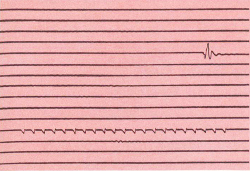
Enlarged portion of a typical pen record of flashes of sunlight from Telstar mirrors, showing a burst of 21 glints from the 68° mirror recorded at 03:40:58 Greenwich Mean Time on August 9, 1962. Synchronizing vibration mark seven lines above the recorded burst indicates the time 02:59:00. Measuring the horizontal distance between consecutive sawtooth marks tells us that the spin rate is between 163 and 164 revolutions per minute. (Precise measurements of the oscilloscope traces fixed the exact spin rate at the time of this burst at 163.64 revolutions per minute.)
Telstar I was launched on July 10, 1962. That evening, beginning on the satellite’s seventh pass, we were able to detect trains of flashes from the mirrors. We assumed that, since Telstar had been launched almost exactly according to plan, its spin axis would be perpendicular to the plane of the earth’s orbit, and we calculated when we should see the flashes. And, each time, we actually saw them within two minutes of the times we had predicted—so we knew that the spin axis was almost exactly where it should be.
Our measurements have continued whenever the weather and other conditions permitted. Combining readings from the bursts of flashes and telemetry data from the solar aspect cells, we have accurately plotted Telstar’s spin axis; it has continued to precess very much as we predicted it would. We have also seen what happens to the spin axis when the satellite’s torque coil is turned on. And, by measuring the intervals between flashes, we have made very precise measurements of the spin rate, which is gradually decreasing mostly according to schedule. However, the plot is showing some small unexplained variations of spin decay rate, and a study of them will, we hope, throw light on some of the variations of the earth’s magnetic field.
For future communications work, particularly with satellites at longer ranges, it would seem to be preferable to use stiffer, flatter mirrors and to make them from beryllium rather than aluminum alloy. More accurate tracking means, more observatory sites, and more powerful telescopes will also be needed. But for this first experimental use our little mirrors have worked very well.
Jeofry S. Courtney-Pratt was born in Hobart, Tasmania, Australia, and received a Bachelor of Engineering degree from the University of Tasmania in 1942 and a Ph.D. from Cambridge University in 1949. He was also awarded an Sc.D. by Cambridge in 1958. He joined Bell Telephone Laboratories in 1958, and has done research in high-speed photography, optics, optical masers, the properties of materials, and the physics of the contact of solids.
Kenneth D. Smith
Electronics Engineer—Member of Staff, Semiconductor Device Laboratory
Before we learned about the Van Allen belts, we expected that the solar cells used to power satellites would last for many years in space. We thought they would be damaged only by cosmic rays, micrometeorites, and occasional bursts of particles from the sun. But when the solar plants of some American satellites went out of action after only a few weeks in orbit, we realized that in the future solar cell power units would need better protection from radiation damage. We had learned that satellites—and particularly medium altitude communications satellites—must spend a lot of time in regions where they will be struck by thousands or even millions of high-speed radiation particles each second.
This fact forced us to change almost all our thinking about solar power plants for satellites. To make sure they would last for several years, we had to design new types of solar cells and devise new ways of mounting them. We also had to revise our estimates of how much power we could expect to get from our cells.
If a communications satellite is to go into regular commercial service, it must continue working for several years in space. The Telstar satellite, however, was designed as an experimental project, and we decided that two years would be a reasonable lifetime to plan for. When Project Telstar began, our problem was to develop solar cells that would operate in an environment subject to strong radiation effects—and keep on operating there for two years.
Our work on the solar cells for Telstar I began in October, 1960. With just a little more than a year to go before the satellite had to be ready, there was no time to lose. So we decided to break down the over-all problem into three parts:
A different group of people began work simultaneously on each of these three parts of the problem, with each of them going ahead under the assumption that the others would be successful. Each group had to find the answers to many very interesting questions, but since our space is limited we can only discuss some of them here. Before doing so, however, we must say something about what a solar cell is and how it works.
There are two ways of making a silicon solar cell. In one, the body of the cell is what we call n-type silicon—that is, pure silicon that has been doped with a small number of impurity atoms of an element such as phosphorus or arsenic (from group V of the periodic table). This kind of semiconductor[4] conducts electricity by means of a supply of free-to-move electrons (negative charges) caused by the presence of these impurity atoms. To make a workable solar cell from n-type silicon, a thin surface layer of p-type silicon is formed by diffusing atoms of a material from group III of the periodic table—usually boron—into the silicon. Metallic contacts then are made to these two regions. This kind of cell is known as a p-on-n cell.
The second type of solar cell is just the reverse. It begins with a body of p-type silicon (with impurity atoms from a group III element) and conducts electricity by means of “holes”—vacant sites where electrons might be but are not. These holes act as free-to-move positive charges. We can make a solar cell from this material by diffusing a layer of n-type impurity, such as phosphorus, into it. We call this an n-on-p cell (see the figure below).

Construction of a silicon solar cell of the n-on-p type (thickness of n-layer greatly exaggerated).
The key to the operation of either type of solar cell is the junction between the regions of n-type and p-type material—what 64 we call the p-n junction. In an actual n-on-p cell this junction is only about twenty millionths of an inch below the surface, since that is the thickness of the n-layer. At this point, where the hole-rich p-region meets the electron-rich n-region, there is a permanent, built-in electric field. As shown in the figure below, the n-layer has many free electrons (indicated by minus signs) and a few holes (circled pluses), while the p-region has many holes and a few electrons. When the cell is in equilibrium, thermal agitation causes some holes to diffuse into the p-region. We call these stray holes and electrons minority carriers (the circled pluses and minuses in the figure). Thus, the n-layer has a slight positive charge and the p-body has a slight negative charge; this results in a difference in potential across the junction, which in silicon amounts to about seven-tenths of a volt.
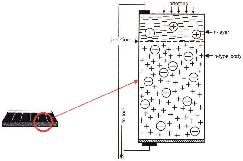
Schematic diagram of an n-on-p solar cell. In the n-layer, minuses represent free electrons, circled pluses are minority-carrier holes; in the p-type body, pluses represent holes, circled minuses are minority-carrier electrons.
Sunlight is made up of individual corpuscles of energy called photons. When these photons are absorbed in or near a cell’s p-n junction, they liberate both a free-to-move negative charge and a free-to-move positive charge—this is called generating a hole-electron pair. The electric field across the p-n junction causes the holes to flow to the p-side and the electrons to the n-side of the barrier. This flow tends to make the p-side positive and the n-side negative, so that, when a load is connected between them, a useful external voltage (amounting to about six-tenths of a volt) is produced, and electric current will flow. Thus, we have converted light energy into electrical energy.
Only part of the energy in light can be used to generate an electrical output, since a good deal of the light striking a cell is absorbed as heat or is reflected from its surface. The percentage of solar energy that can be converted into usable electric power is called the cell’s conversion factor or efficiency. Although this can theoretically be as high as 22%, the best cells we have made in the laboratory have conversion factors of only about 15%, and the better commercial cells have efficiencies of 12% or more.
Although both p-on-n and n-on-p cells were made in early laboratory studies, the p-on-n cells gave a somewhat higher output. As a result, all the American commercial solar cells up to 1960 were of this type, and they were used on all satellites before Telstar I. (Russian satellites, we believe, have used n-on-p cells from the beginning.)
The U.S. Army Signal Corps Research and Development Laboratory, however, decided to make both p-on-n and n-on-p cells and compare their performance. This laboratory work led to a surprising discovery: The n-on-p cells were several times as resistant to energetic particle radiation as were comparable p-on-n cells. These results were announced in 1960, and confirmed by our measurements and those of other laboratories. The timing was very fortunate, since we had just learned of the greatly increased radiation hazards presented by the Van Allen belts.
Now, having given you a very brief account of how a solar cell works, let us return to our three-part problem. The first objective was to study all the aspects of radiation damage. To do this, we had to find out how much radiation the Telstar satellite would encounter; we needed to estimate the concentration of high-energy particles—both electrons and protons—at various altitudes and locations. Several government agencies are now carrying on research in this important area, but at the time of the Telstar I launch we did not know exactly how much radiation the satellite would run into. And the high-altitude nuclear explosion of July 9, 1962 (the day before Telstar I went into orbit) may have increased the quantity of high-energy electrons injected into its path.
We also wanted to find out whether electrons and protons would do the same damage to solar cells. Several kinds of cells were exposed at Bell Laboratories and at various university research laboratories to a wide range of radiation dosages. The experiments showed, generally, that the damage effects of electrons and protons should be about the same. Although protons are 1840 times as massive as electrons, there are a great many more electrons in the Van Allen belts, so that an unprotected solar cell would be much more likely to be injured by electrons than by protons.
In fact, we found that the Van Allen belt protons have so much energy that they can go through transparent shielding material as much as several centimeters thick and still damage a solar cell. Thus, to screen our cells from protons we would need very thick transparent cover plates, and this added weight would be intolerable. So we decided to use no proton shielding at all.
With electrons, the situation is different; they are much lighter and have much less energy. Also, if their energy is reduced below a certain level (about 180 thousand electron volts) electrons will not be able to knock silicon atoms out of position, and thus cannot harm a solar cell. We experimented with a number of different kinds and thicknesses of cover plates, and found that transparent material with a mass of 0.3 gram per square centimeter would slow down electrons enough to make them no problem.
Another radiation study helped us take advantage of the fact that solar cells respond differently to light of different wave lengths. If the surface layer of a cell is extremely thin, it will absorb blue, green, and yellow light well, but may be much less sensitive to the deeply penetrating red and infrared waves. We experimented with n-on-p cells having very shallow p-n junctions, exposing them to an extremely strong radiation dosage. The cells still responded very well to blue and green light, even though most of their response to infrared and red light was lost. These findings convinced us that we should work to make our new cells as blue-green sensitive as possible, since they were going to be exposed to heavy radiation.
After it was discovered that the n-on-p cell was more resistant to radiation, we decided to make an all-out effort to develop an n-on-p cell that could be manufactured in quantity for our new satellite. Since we didn’t know whether we could solve this problem in time to meet the Telstar I launch date, we “hedged” by designing the new n-on-p cells to be the same physical size (one by two centimeters) as conventional p-on-n cells. Thus, if the n-on-p project hit a snag, we probably could use regular p-on-n cells.
As you can imagine, making a solar cell to fit the very high requirements we had set for the Telstar satellite is not an easy job—and making these cells by the thousands is even more of a task. During October, November, and December of 1960 we carried on a crash program in which we made hundreds of experimental cells in our laboratories, using a variety of materials and many different manufacturing techniques.
We perfected a phosphorus diffusion process to develop the very thin n-layer (about one forty-thousandth of an inch thick) that we needed for our special blue-sensitive n-on-p cells. We also had to devise an entirely new way to attach the metallic contacts to the highly polished surfaces of our cells, using a combination of titanium and silver.
Some tricky manufacturing problems also had to be solved once the Western Electric Company began to make the large quantity of cells needed for the Telstar program. For example, during the diffusion of the n-layer of the cell, the silicon slice is surrounded by phosphorus pentoxide vapor, which covers the entire slice with an “n-skin.” This skin must be removed from the bottom of the cell by etching or grit blasting before the p-contact is applied. Another difficult problem occurred when we decided to give our cells an anti-reflection coating. Because polished silicon has a refractive index near 4 and space has an index of 1, silicon will reflect about 34% of visible light from the sun. However, if we apply an anti-reflection layer onto the silicon this percentage of reflection can be considerably decreased. We found that the best substance for this purpose was a layer of silicon monoxide only three-millionths of an inch thick. But it was only after quite a bit of trouble—and scrapping several thousand cells—that we were able to get this coating to adhere properly in the right thickness.
The third part of our problem had to do with finding the best ways to mount and protect the cells on the Telstar satellite itself. Since a satellite’s solar power plant usually has several thousand cells, we find it best to mount the cells in groups, or modules. These can be pretested as a unit after individual interconnections have been made. For Telstar I, we decided to mount the 3600 solar cells in 12-cell modules like those shown in the figure below.
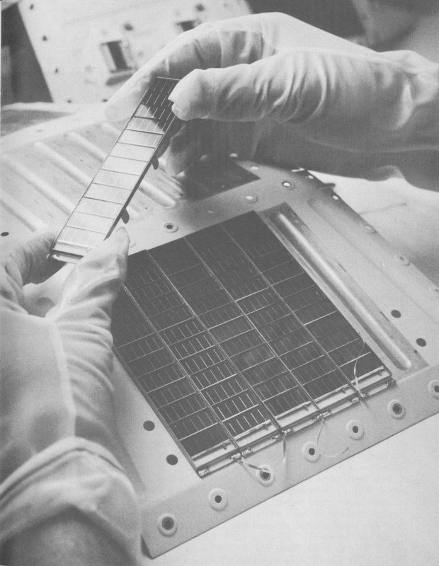
The satellite uses 300 modules of twelve solar cells, in groups of six or three modules per facet.
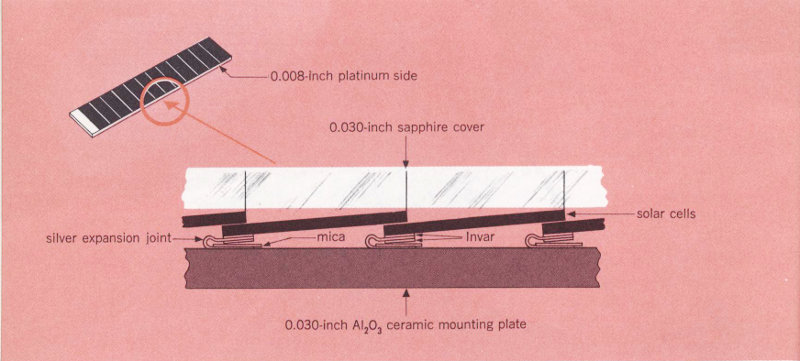
Lengthwise diagram of a solar cell module, showing how individual cells were fixed in place.
Each of the cells has a top contact along one edge and a bottom contact all over its base, so we were able to assemble the 12-cell groups like shingles, with the bottom edge of one cell covering the top edge of the next, leaving only the active area of each cell exposed. But this meant that each module would be over four inches long and only 14 thousandths of an inch thick—far too weak to withstand stress and vibration. To support the cells, we decided to mount them on a metallized ceramic base. But this presented a problem: If the cells were soldered directly to the base, the different thermal expansion rates of the silicon and the ceramic would cause the structure to break during the cycles of extreme changes in temperature that Telstar would pass through. We remedied this by connecting each cell to the ceramic support by a thin U-shaped strip of silver (see above). Since silver has a much higher thermal expansion coefficient than silicon, we added tiny sandwiches of Nilvar or Invar (36% nickel, 64% iron) where the cells were attached. With this mounting method, the cell modules withstood thermal and mechanical shocks much more severe than those they would undergo in actual use. In one test, for instance, an entire cell module with its cover plates was first dipped in hot water, then plunged into liquid nitrogen at a temperature of -195° Centigrade. In orbit, the temperature range for the satellite was not expected to be more than from +80° to -100°C, with a rate of change of no more than three degrees a minute.
Finally, we needed to find the right kind of transparent protective cover for the Telstar solar cells, both to keep micrometeorites from damaging the sensitive and very thin diffused layer and to slow down the incoming electrons to nondestructive energy levels. For micrometeorite protection, only a thin layer of hard transparent substance was needed; for electron protection, the cover plates should have a mass of no less than 0.3 gram per square centimeter (as we explained above). And there were two other important considerations: The material we used should not be darkened or discolored by prolonged exposure to ultraviolet radiation, and it should have good thermal conductance, so that some of the heat absorbed by the solar cells could be conducted out to the cover plates and re-radiated. All these requirements led us to 69 the choice of clear, man-made sapphire. Although sapphire is more expensive and difficult to make than the equivalent quartz or glass, it only has to be 30 mils (three hundreds of an inch) thick. Twice this thickness would be required if quartz or glass were used.
We have had space to describe only a few of the things involved in designing a solar cell power plant that would work unattended out in space. We have not mentioned a good many of the tough problems that had to be worked on. But we are glad to report that we could find answers to almost all our questions. And the most significant answer is shown in the figure below, where you can see how the Telstar I solar power plant slowly diminished in power almost exactly as we predicted it would.
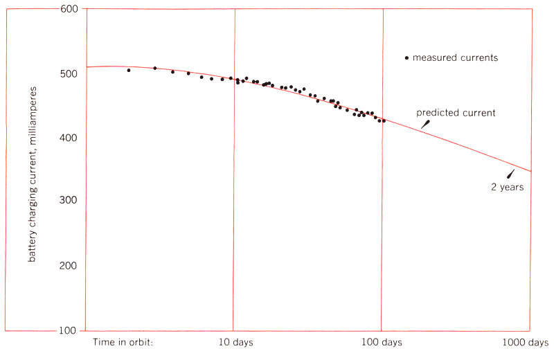
Very gradual decay due to radiation effects of the Telstar I solar cell plant in the first months after the satellite went into orbit; it was extremely close to the predicted rate (solid line).
Kenneth D. Smith was born in Galesburg, Illinois, and received a B.A. from Pomona College in 1928 and an M.A. from Dartmouth College in 1930. He joined Bell Telephone Laboratories in 1930, and has worked on the development of proximity fuzes, radar bombing systems, broadband microwave radio systems, and various semiconductor devices, including radiation-resistant solar cells for the Telstar satellite.
Peter D. Bricker
Psychologist—Member of Staff, Behavioral Research Laboratory
One of the satellite communications systems that has been proposed would make use of stationary synchronous satellites. These would be precisely located above the earth’s equator in orbits 22,300 miles high, where they would circle the earth once every 24 hours, and thus appear to remain stationary over a point on the earth. There are several advantages to this type of system—the most important being that we would need only three satellites for communications between almost all the inhabited regions of the earth.
On the other hand, there are several problems in establishing a synchronous system. Just getting the satellites into exactly the right places and keeping them in position is a formidable one. We also have something of a mystery to contend with, because of the tremendous distances that would be involved. Although we can communicate at speeds close to that of light—186,000 miles per second—we cannot go any faster than that. You might think that 186,000 miles a second was fast enough for us, and most of the time it is. However, if you send signals 22,300 miles up into the sky, transmit them back to earth, perhaps send them up again to a second satellite, and finally bring them 22,300 miles back down to earth, even the speed of light may not be fast enough. The delay will be only about a second or so, but it may—for some kinds of communications—be long enough to cause trouble. How much trouble, we don’t yet know.
For one-way signals such as television, a transmission delay of about one second obviously makes little or no difference. But for two-way conversations on the telephone, where there is rapid back-and-forth talking, even this tiny amount of time delay may be a problem. And then again, it may not be. There have been a lot of experiments to find out something about this delay problem, and these have given us a lot of different answers. Work is still going on, and there is still much to find out. In this chapter, we tell you about one small, early experiment. Its results were not conclusive, but they should give you one example of how to set up and carry out a typical experimental study on human behavior.
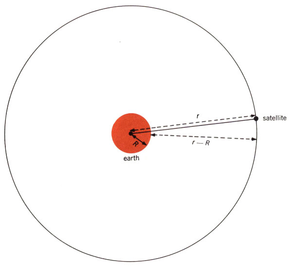
Typical circular satellite orbit: r is distance from center of earth to satellite; R is radius of earth.
For our purposes, we will not be concerned with all the problems of launching a synchronous satellite into its proper orbit. But you may be curious why we know that this orbit must be 22,300 miles high. It can be calculated by using two basic formulas from elementary physics.
From Newton’s Law of Gravitation we know that the velocity, v, of a satellite moving in a circular orbit[5] will be
| gR² |
| r |
where R is the radius of the earth, r is the distance from the center of the earth to the satellite, and g is the acceleration due to gravity (see diagram above).
We also know that this velocity must be
| 2πr |
| T |
since the distance the satellite travels to complete an orbit is 2πr, and T is the time of one complete revolution. Thus we have the equality
| gR² |
| r |
| 2πr |
| T |
and, solving for r, we get
| gR²T² |
| 4π² |
| ⅓ |
Since we are interested in a synchronous satellite, T in this case will be 24 hours. We can now find r (using g = 32 feet per second per second and R = 3960 miles), and then obtain the distance r - R, which will be 22,300 miles. By using our previous formulas, we also can find the velocity of a satellite moving in this orbit, which will turn out to be v = 6870 miles per hour.
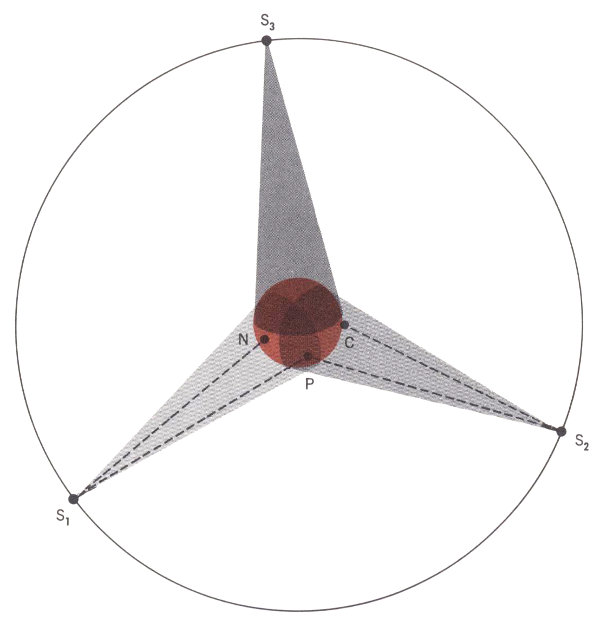
One possible method of using synchronous satellites. Signals from New York (N) to Paris (P) would go via satellite S₁; signals from New York to Calcutta (C) would go via satellites S₁ and S₂.
The illustration above gives a rough idea of how a synchronous satellite system might be set up. Three communications satellites, S₁, S₂, and S₃, are above the equator in fixed positions equal distances apart and 22,300 miles up. Located in this manner, they would cover the major part of the earth’s surface. From a point directly beneath it, the distance would be 22,300 miles to a satellite; from other points the slant range would be greater. Signals sent from, say, New York (point N) to Paris (point P) would be reflected via satellite S₁. In doing this, they would travel a total distance of about 46,000 miles. Because we can’t send signals any faster than the speed of light (186,000 miles per second), it would take at least a quarter of a second for a signal to go this far. For communicating a much greater distance, say from New York to Calcutta (point C), the signal path would use two satellites, S₁ and S₂. In this case, the total distance traveled by a signal would be more than 90,000 miles, and the one-way time delay would be about half a second.
Delays of a quarter- or half-second have different effects on various kinds of communications. However, we are concerned here only with what they might do to telephone 73 conversations. Time delay will affect conversations in two ways. One of these—pure delay—depends on the nature of speech and the way people use it to converse; the other—echo—has to do with the nature of the world’s telephone systems.
The first effect can be illustrated by an example. Suppose that George in Paris is talking to me in New York. He says, “Do you want to go?” and I answer “Yes” immediately upon hearing the word “go.” But that word didn’t arrive in New York until a quarter of a second after George said it, and my reply was delayed another quarter-second, so George hears my instantaneous reply a half-second late. Under some circumstances, he might interpret this delay to mean that I was less than enthusiastic about going. We don’t know exactly what response times people expect in conversation, or how much variation in such intervals they can tolerate. But it has been assumed that delays of a half-second or more would make a noticeable and perhaps disturbing difference. A little later on, I will describe an experiment dealing with this first effect. But first we must briefly discuss the second effect of delay on telephone conversation, to show why we decided to try to isolate the first effect and study it separately.
All the world’s telephones are individually connected to the rest of the system by what we call two-wire local loops. Speech travels in both directions on the same wires over these local parts of the circuit. In other parts of the system, where speech travels farther and must be amplified, it is carried over four-wire circuits. These consist of two pairs of wires, one for transmission in each direction. At the junctions where the two-wire and four-wire parts of the telephone system meet, specially designed transformers, called hybrid coils, are used.
It is impossible to have these junctions between two-wire and four-wire circuits always in perfect balance, so part of the speech that reaches a local loop will be reflected back along the path on which it arrived. Unless a circuit has been specially treated, this reflected speech will get all the way back to where it started, and the talker will hear an echo of his own voice. When the circuit is short enough, the echo is heard almost instantaneously, and is not bothersome. But when the echo is delayed by a twentieth of a second or more, it can become extremely annoying, and even temporarily destroy one’s ability to speak coherently.
Telephone engineers have long been aware that this echo effect was present on their long-distance circuits, and they have not let it go unchecked. Devices known as echo suppressors are installed on circuits that have more than a critical amount of delay. They are placed in a four-wire part of the circuit, where there is one-way transmission over each pair. Since incoming and outgoing sounds are using separate paths, an echo suppressor can attenuate or shut off the return path when speech is coming in on the other path.
Unfortunately, echo suppressors have effects of their own on transmission. They may, for example, cut off some speech that should be getting through, because they can’t distinguish it from echo. Echo suppressors can be made more sophisticated, but whether they can be made to operate more successfully than present ones is not clear. And the problem of adapting them to the long delays of synchronous satellite circuits will require a great deal of research and development effort.
Although we don’t know how good echo suppressors can get, we do know that a long circuit with the best possible suppressors could never be better than a circuit of the same length that had no echos. This brings us back to the problem of how serious the effect of delay alone is on conversations. If the delay in a synchronous satellite system, even without any echo, made conversation all but impossible, there would be little point in developing echo suppressors for such satellites.
This question looked like one that we could answer, at least in part, by experimenting with special four-wire circuits that had delay but no echo. The strategy we adopted, then, was to do some experiments on pure delay while other people at Bell Telephone Laboratories began to attack the problem of testing and improving echo suppressors. In the pages that follow, I will describe one of our experiments on the pure delay problem. More elaborate ones have been performed since, and there will be more to come.
It should now be clear how this sort of experiment might be helpful to the development of a synchronous satellite communications system. If it showed pretty convincingly that conversation was extremely difficult with a pure echo-free delay of about a second, synchronous satellites for two-way conversations would be less practical. On the other hand, if the experiment were to show that some conversation, at least, could be carried on without too much difficulty, our results would be less decisive. We would know only that echo-free delayed circuits might sometimes be all right. But we would not know how bad they were under a variety of conditions or how closely they resembled a real circuit with echoes and echo suppressors. In either case, the experiment would have no bearing on the use of synchronous satellites for one-way purposes, such as television.
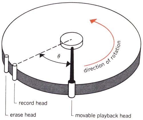
Recording equipment used in the experiment.
| θ |
| 360 |
“Can people converse over an echo-free, four-wire circuit that has delay like that of a synchronous satellite?”—that is one way of putting the question we isolated to study. The next problem was to find a way of setting up this question in the form of an experiment whose results might be interpreted as a meaningful answer. The problem of apparatus, fortunately, was fairly simple. Two telephone sets in separate rooms were connected by four wires, with one pair going directly from each transmitter to the other receiver, so that no echo would go back the way it came. This gave us the “echo-free, four-wire circuit” we wanted. To simulate the satellite, I inserted a magnetic delay device (see sketch) between one of the 75 transmitters and the other receiver. This had a revolving drum on which speech could be recorded and then played back a short interval later. By moving the playback head, I could produce any amount of delay up to two satellite bounces’ worth. At this point, the equipment was ready, but there were still two major problems: (1) how to get people to converse over the circuit in a natural way, and (2) what to observe and measure that would give us an answer to our question.
When you think about the first problem, you soon realize that it is hard to say exactly what a “natural” conversation is. But even if we can’t describe it, we can try to find examples of it. I experimented with several ways of making people talk that could be recognized as unnatural: word games, list-checking, shape description and recognition, and a system of rewards for spurts of talk. None of these schemes seemed to generate the real conversational interplay we wanted. Finally, I noticed that my coworkers often got involved in vigorous conversations on political and social issues at the lunch table. So I circulated a questionnaire to help me pick pairs of people who might enter into lively discussions on one or more topics. I arranged seven conversations of this sort, and they became the basic material of my study. Only one of these lacked sufficient spirit to yield good data, and six out of seven is a pretty good percentage when you try to study human behavior in such a free situation. Note that the conversers expressed ideas that came from within them at the time—not from any external materials—and that they usually felt rather strongly about what they were saying to the other fellow, who disagreed and therefore needed some convincing. Of course, these conversations do not represent the whole range of possible conversations; they are only a small sample of one type. This doesn’t limit the truth of the particular result we got, but it does limit how far we may generalize from these results.
You might think we could solve this problem simply by asking the conversers their opinions. We found out long ago, however, that the opinions you get are affected by a lot of things: how you ask the question, the attitude of the respondent, and his unrelated experiences outside the experiment. So we usually try a more subtle approach. In this case, my basic observation was of what psychologists call escape behavior. The conversers were told that they would start talking over a normal circuit, and that delay would be introduced at some point. (The delay was inserted in such a way that an abrupt change could not be noticed.) All the conversers had pushbuttons for signaling the experimenter. If they thought they noticed a delay, they were told that it would be removed if they pushed the button. Thus they could always escape from this possibly unpleasant condition.
My reasoning was this: If the conversers found it very difficult to talk with delay in the circuit, they would surely push the button soon after the delay was introduced. On the other hand, any time when they continued to converse without pushing the button—while delay was in the circuit—was obviously also a time when the delay did not make conversation impossible. So we had at least one measurable quantity—the time taken to detect delay—which we could interpret as an answer to our question. Note that we could tell if people pushed the button “just to be on the safe side” by seeing how often they did this when there actually was no delay in the circuit.
There are just a few more necessary details before we discuss the results:
Now we could answer the question, “How long does it take people to detect 1.2 seconds of delay?” As you can see from the table opposite, the times ranged all the way from 20 seconds to over 10 minutes, and, in two cases delay was not detected at all. The results in the table are also shown in the histogram on the next page, which depicts how broadly the detection times were distributed. To me, one of the most interesting things is that even people who were able to detect delay quickly sometimes did not detect it for a couple of minutes. For example, the pair K/G had two times under a minute, one of 143 seconds, and one of 421 seconds. I interpret their two short times to mean that they knew what to look for, since they made no incorrect responses while delay was not present. However, their long times seem to mean that they sometimes didn’t notice delay for quite a while. Incidentally, only two responses were made during the total of about 40 minutes when I did not introduce delay, and these “false alarms” were by two of the fastest pairs at true detection—F/K and S/H.
| PAIRS OF TALKERS | NUMBER OF SECONDS BEFORE TALKERS DETECTED DELAY |
|---|---|
| G/H | 161 |
| 224 | |
| 107 | |
| F/K | 87 |
| 65 | |
| 43 | |
| 220 | |
| false alarm | |
| A/L | 618 |
| 95 | |
| 367 | |
| F/T | no detection after 954 seconds |
| S/H | 227 |
| false alarm | |
| 90 | |
| 75 | |
| 83 | |
| K/G | 38 |
| 421 | |
| 20 | |
| 143 | |
| S/W | 257 |
| 229 | |
| no detection after 260 seconds | |
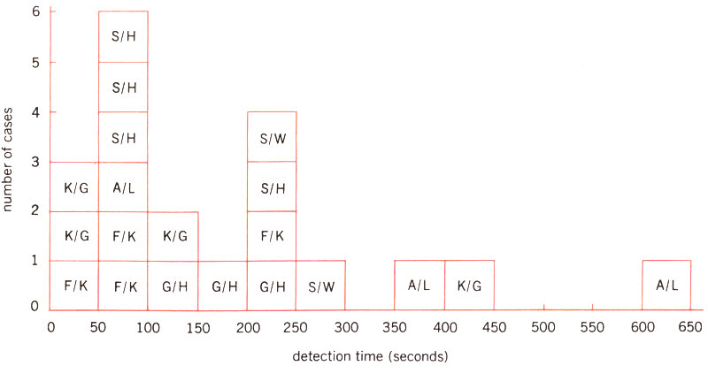
Data from table have been arranged in this histogram to show wide range of delay detection times that were recorded in the experiment. Each block represents a single delay detection, identified by initials of conversers.
| number of cases | ||||||||||||||||||||||||||
| 6 | ||||||||||||||||||||||||||
| S/H | ||||||||||||||||||||||||||
| 5 | ||||||||||||||||||||||||||
| S/H | ||||||||||||||||||||||||||
| 4 | ||||||||||||||||||||||||||
| S/H | S/W | |||||||||||||||||||||||||
| 3 | ||||||||||||||||||||||||||
| K/G | A/L | S/H | ||||||||||||||||||||||||
| 2 | ||||||||||||||||||||||||||
| K/G | F/K | K/G | F/K | |||||||||||||||||||||||
| 1 | ||||||||||||||||||||||||||
| F/K | F/K | G/H | G/H | S/W | A/L | K/G | A/L | |||||||||||||||||||
| 0 | ||||||||||||||||||||||||||
| 0 | 50 | 100 | 150 | 200 | 250 | 300 | 350 | 400 | 450 | 500 | 550 | 600 | 650 | |||||||||||||
| detection time (seconds) | ||||||||||||||||||||||||||
Now, to answer our question about whether people can converse over our circuit, we can say something like this: We have found some cases (of a certain type of conversation) where people can use a circuit with 1.2 seconds of echo-free delay for the amounts of time listed in our table. But there are two important things to remember about our results:
Since we didn’t get a “no” answer to our question, we have been encouraged to do more experiments with other subjects and other types of conversations. We also have begun to look for more than a yes-or-no answer; we now want to find out how serious various amounts of pure delay would be. Some of my colleagues have been working on this problem by furnishing special four-wire telephones to a group of people, so that echo-free delay can be inserted in the line when one member of this test group calls another member. Their experiment has confirmed our finding that conversation with a round-trip pure delay of 1.2 seconds is not impossible, but it has also shown that the degradation of conversation that results is not trivial.
Recently an international committee on commercial telephone standards set the maximum permissible echo-free delay (round-trip) at 0.7 seconds. However, the search for a more precise evaluation is still going on.
Peter D. Bricker was born in Scranton, Pennsylvania, and received an A.B. from Bucknell University in 1950 and an M.A. in 1952 and a Ph.D. in 1954 from the Johns Hopkins University. He joined Bell Telephone Laboratories in 1954, and has been engaged in psychological studies of telephone color preferences, pushbutton set designs, voice identification, and transmission quality evaluation.
E. Jared Reid
Electrical Engineer—Member of Staff, Satellite Design Department
It is hard enough to fix a new piece of scientific equipment when it goes out of order in the laboratory. And when the equipment is sailing around the earth a couple of thousand miles up in the sky a repair job ought to be impossible. But during the last two months of 1962 we found this not to be true at all. That was when the Telstar I satellite began to misbehave and eventually would not obey the commands we sent it from the ground. This presented us with a nice little problem: We had to find out exactly what was wrong with the satellite and then—the really tough job—devise a way to cure the trouble. We were able, finally, to do both these things, after a combination of logical deduction, trial-and-error experimentation, and laboratory testing—plus a certain amount of plain good luck. Our “cure,” unfortunately, turned out to be only a temporary one, for our patient had a relapse some weeks later. However, the story of how we went about doing our never-before-attempted task should give you an idea of the things you have to improvise in the laboratory when an experiment doesn’t work out exactly as you had planned.
As shown on pages 32 and 33, the operation of the Telstar I satellite was controlled by orders sent from the ground on a frequency of 123 megacycles. Fifteen different commands could be given to the satellite, each a coded signal made up of a series of ones and zeros. The signals, as you can see in the table below, turn on or off the radiation experiments, the telemetry, the communications equipment, and the orientation coil. These are important functions, and we wanted them to be going on when they were needed. But we did not want them to be operating continuously.
Command was the only Telstar I function that we felt had to be “redundant,” so two duplicate chains of components were provided. As you can see in the block diagram on the next page, the satellite has two radio receivers in parallel, so that one can operate if the other fails. There are also two command decoders, which take the pulse-coded signals from the receivers and translate their zeros and ones into usable instructions. In the command switching control, these instructions operate nine relays that turn on or off the power to all the electronic circuits except the command receiving chain, which operates continuously.
Telstar I’s telemetry unit reported back 112 measurements every minute over the 136-megacycle frequency. These told both what the satellite encountered in space and the condition of the satellite’s own components—as indicated by a variety of different sensors. The telemetry also gave a check on whether the commands sent to the satellite were actually obeyed.
| COMMAND | FUNCTION |
|---|---|
| A | Turns on traveling-wave tube filament voltage |
| B | Turns on traveling-wave tube helix and collector voltages; energizes all transistor circuits associated with communications experiments |
| AA | Turns off traveling-wave tube helix, collector, and filament voltages; de-energizes transistor circuits |
| C | Turns on traveling-wave tube by applying anode voltage |
| CC | Turns off traveling-wave tube anode voltage |
| D | Turns on telemetry and energizes radiation experiment circuits |
| DD | Turns off telemetry and de-energizes radiation experiment circuits |
| E | Turns on current in orientation torque coil |
| EE | Turns off current in orientation torque coil |
| F | Connects telemetry encoder No. 1 to circuit |
| FF | Connects telemetry encoder No. 2 to circuit |
| SS | Performs duties of AA, CC, DD, EE, and FF; de-energizes 136-mc beacon transmitter and removes all load from storage battery |
| S | Connects storage battery back into the circuit and energizes the 136-mc beacon transmitter |
| T1 | Turns off command receiver and decoder No. 2 for 15 seconds, so that command receiver and decoder No. 1 can be tested |
| T2 | Turns off command receiver and decoder No. 1 so that No. 2 can be tested |
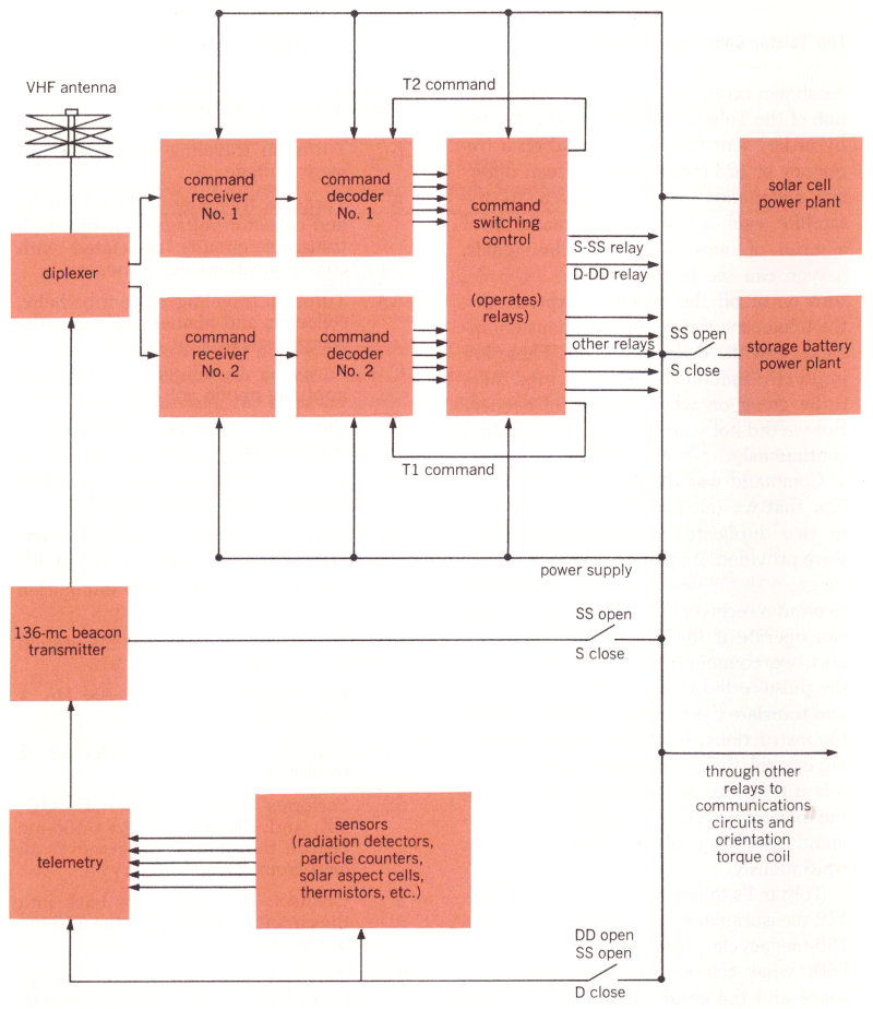
This block diagram of Telstar I’s command circuit shows the redundant receiver and decoder chains, No. 1 and No. 2, which are fed the command signals from the ground that are picked up by the VHF antenna. Decoded instructions go to the command switching control, which operates relays to turn equipment on or off. Reports on the operation of this control are sent back by telemetry to the ground station along with information from the satellite’s sensors.
During Telstar I’s first two months in orbit, the only indication of trouble cropped up in one of the command operations. Telemetry told us that the satellite was no longer executing the T2 command. This meant that we could not temporarily disconnect command chain No. 1 to check the performance of chain No. 2. Then, a short while later, No. 2 began to give intermittent operation. Finally it failed completely. At the time, we didn’t know why this had happened, but, since the satellite’s other command chain still seemed to be operating normally, we were not very worried.
However, in the middle of November 1962 command chain No. 1 also began to be intermittent. We would send a command but get no response from the satellite; only after we repeated it a few times would the satellite finally do what it had been told to do. Now there was something to be concerned about. And, if chain No. 1 should fail, we had to make sure that Telstar would be left in a favorable operating condition. We didn’t want the satellite’s communications equipment to be left on without our being able to turn it off—this would keep a continuous drain on the power supply.
As we feared it would, the other command circuit went out of commission on November 23rd. However, when this happened, the communications circuits had been turned off, although the command chains themselves and the telemetry remained on. This meant that we could still try to send commands, the condition of the satellite could still be monitored by telemetry, and the solar cells could still supply useful power. But, since we could not turn the communications equipment on, Telstar I could no longer be used for transatlantic television or any of the experiments we had been carrying on successfully since July.
At this point a number of Bell Telephone Laboratories engineers began to analyze Telstar’s troubles. As you can imagine, we had a rather difficult problem. We obviously could neither go up and look at Telstar nor bring it down for an overhaul on the ground. We could only send different commands to the satellite and watch the telemetry data to see what, if anything, happened.
After checking the satellite’s other equipment, we were happy to find that everything except the command chains was in good condition. So we decided the trouble had to be one of five possibilities:
We could quickly narrow this list down. Telemetry indicated that the receiver was not being blocked by noise. Reports from the temperature-measuring thermistors told us that inside the satellite the temperature was 75 degrees Fahrenheit, just as it should be. A loose connection was very unlikely, because every one had been made by expert wiremen, examined by trained inspectors, and then completely encapsulated in polyurethane foam. Aging also seemed very improbable, since all the components had been individually tested and selected for the highest reliability and longest life.
This left only radiation damage. We had other good reasons to suspect this, too. As far back as October 1961, scientists at Bell Labs and Brookhaven National Laboratories had made an important discovery about the effect of radiation on a transistor. They found that, when radiation penetrates the outer shell of a transistor and ionizes the gases inside, electrically charged particles (ions) tend to collect on the surface and change the transistor’s electric properties. This effect is particularly noticeable when a transistor is operating under reverse bias voltage. We knew that some of the 37 transistors used in each Telstar I decoder circuit were operating under continuous reverse bias and that they also had less metal shielding than did those semiconductors in the telemetry and receiver circuits.
Telstar’s radiation detectors had been telling us that the concentration of high-energy electrons near the inner edge of the Van Allen belt was greater than we had expected. We now know this may have come as a result of man-made high-altitude nuclear explosions, one of which took place the day before Telstar I was launched. But we had had no reason to anticipate this extra radiation—it was more than one hundred times the predicted level—when we tested the transistors to be used in Telstar I. So we were not too surprised that they were more susceptible to radiation damage than we had thought they would be.
All this seemed to give us a theoretical explanation for the trouble. So, after November 23rd, we began looking for laboratory evidence to confirm our radiation theory. First, two engineers traveled down to Johannesburg, South Africa. At this time the highest point of Telstar’s orbit—when it passes through the least Van Allen belt radiation—was over the southern hemisphere, and it seemed a good idea to command the satellite when it was under the condition of lowest radiation and see if anything would happen. However, everything the engineers tried proved fruitless.
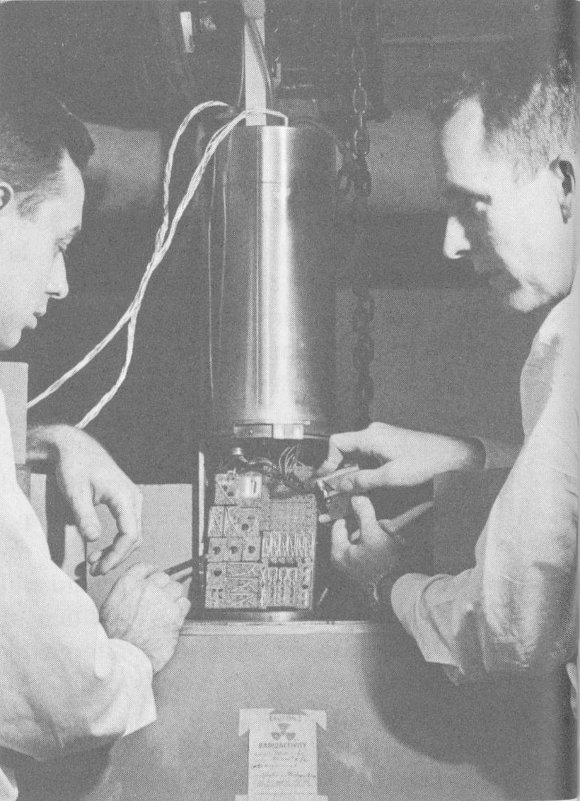
A duplicate of one of Telstar I’s command decoders, containing 37 transistors and 191 diodes, being placed in a small elevator that will lower it into a gamma radiation chamber.
At our Murray Hill, New Jersey, laboratories we worked on a different approach. We exposed transistors like those used in the decoders to large doses of radiation. We also exposed entire spare decoder units to accelerated radiation to find out where their weakest points were (see illustration). And then we built and 83 tested decoders using radiation-resistant transistors to see if they worked better. After a week of intensive laboratory work, we had some pretty good evidence. The tests of individual transistors definitely showed that heavy radiation would cause them to deteriorate. Testing of the complete decoders also led to some failures, and, when we analyzed them, they turned out to be the kind that would be caused by faulty transistors. We also discovered that the most sensitive part of a decoder circuit was the zero gate, which recognizes the zeros in the one-and-zero code that commands the satellite.
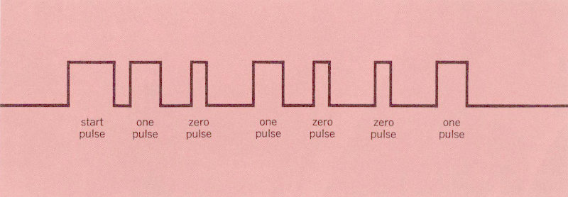
A typical command signal sent to Telstar I. It consists of seven pulses: a three-unit “start” pulse and a binary code made up of three two-unit “one” pulses and three one-unit “zero” pulses.
Now we thought we knew the guilty component, but the hardest job still lay ahead of us. We had to do something to the commands so that they would bypass this troublesome zero gate. Each of the fifteen satellite commands is a binary code of seven pulses, as illustrated in the diagram above. The first—the start pulse—is three units wide. Then follow six more pulses of which three are two units wide (one pulses) and three are one unit wide (zero pulses). The arrangement of this group of six ones and zeros determines the particular command.
Each time a one pulse arrives at the decoder, a one gate counts the pulse and stores a one in its memory. A zero gate counts the zero pulses, but does not store anything. So, if the zero gate is blocked, the decoder will not count the zeros in any of the coded commands and thus cannot decode them properly.

The special “notched one” pulse that was invented to fool Telstar I command decoder.
What could be done about this? The answer seemed to be to devise a new type of pulse—a pulse that would be enough like a one so that it would pass through the one gate and advance the counter, but, at the same time, be enough unlike a one so that the one gate would not store it in its memory. This led to the invention of the special long pulse with a dip or notch in it that is shown in the diagram above. When we tested it in the laboratory 84 on one of the duplicate decoders we had exposed to radiation, this new notched pulse worked as we hoped it would. It passed through the one gate and advanced the counter, but was not stored as a one in the one gate’s memory. Thus it fooled the decoder by doing just what a zero is supposed to do, even though it had gone through the one gate rather than the zero gate.
Magnetic tapes of special codes using notched ones in place of zeros being prepared for use.
But the real test was yet to come. Special modified signals for two of the fifteen Telstar commands, using our new notched ones in place of the usual zeros, were put on magnetic tape (see photograph). Then, on December 20th, when Telstar made its 1492nd pass over Andover, Maine, a group of tired engineers huddled about the mass of equipment they had assembled. Finally, on the third try, the notched pulses were successful; Telstar’s telemetry flashed back the word that the proper relay had operated upon command.
We now wanted to get Telstar to do something that had seemed to work in the laboratory. The transistors most affected by radiation were those operating under continuous reverse bias, to whose surfaces unwanted ions were attracted. If we removed the voltage from these transistors, we felt that the ionization layer would be dissipated, and they would act normally again. Our plan was to prepare a complete taped program of all fifteen commands, and carefully disconnect Telstar’s storage battery (using command SS). Then, when the satellite went into eclipse, there would be no power available from the solar cells either, and—if our calculation was right—the 85 complete lack of voltage ought to restore the transistors to working order. This was a hazardous procedure, for if something went wrong we might have a completely silent satellite on our hands.
As it turned out, an accident did happen—but one of a different and much more fortunate kind. On December 27th Telstar misinterpreted our “trick” commands and disconnected its own battery before we asked it to. Then, as the satellite went into the earth’s shadow, we held our breath while all its power stopped and the telemetry went silent. But, as we had hoped, a rest period with all power removed from the deteriorated transistors apparently made them work almost normally once again. On January 1, 1963, we were able to disconnect the battery in regular fashion—that is, using the one-and-zero code. After this was done, and all power had been removed, both decoders again would operate when given normal commands (actually, the first one restored to duty was decoder No. 2, which had gone out of order first, back in August).
For more than a month Telstar I behaved as it should, and our communications experiments, including television broadcasts, were resumed on January 3rd. During this time we used both normal commands and our special notched-pulse modified commands. Whenever normal commands became intermittent we used the modified commands to disconnect the battery for several eclipses.
Our good fortune, however, did not last. Continued exposure to radiation apparently led to further damage to Telstar I’s transistors. By February 14th, disconnecting the storage battery no longer returned the decoder to normal, and we could operate only with our modified commands. And, on the 21st, the satellite apparently misinterpreted a command, disconnected its storage battery, and went silent. Since then, none of our modified commands has been able to bring back its voice. There is still a possibility that Telstar I may recover if it remains out of the high-radiation part of space for a long enough period—but as time goes by this appears less likely.
However, our work was not in vain. Because we pinpointed the effects of radiation on the transistors in Telstar I, this problem was counteracted on the Telstar II satellite launched on May 7, 1963 (see page 31). To avoid the worst of the radiation effects, the second Telstar is in a considerably larger orbit, which causes it to spend less time in the heaviest high-energy Van Allen belt regions. It carries new radiation detectors with much greater measuring capacity. And in one of Telstar II’s command decoders we are using a new type of transistor, which we hope will not be affected nearly as much by radiation as were the ones in Telstar I’s ill-fated decoders.
E. Jared Reid was born in Hartford, Connecticut, and received a B.S. from Trinity College in 1956, a B.E.E. from Rensselaer Polytechnic Institute in 1957, and an M.E.E. from New York University in 1959. He joined Bell Telephone Laboratories in 1957, and has worked on the design and testing of the Time Assignment Speech Interpolation (TASI) system for the transatlantic cable, as well as on transistor circuits for the Telstar satellite.
Now, having read Part II of Satellite Communications Physics, you should have an idea how we predict the orbit of an artificial satellite and how we find out where it points while passing a thousand miles above our heads. You can see how we pick the best material to cover its surface with and how we protect its solar cells from the hazards of space. And you have watched the steps we would take when our satellite stops working properly.
It would, we admit, take a little more experience to solve problems like these on your own—and to deal with all the other complications of satellite communications. But we hope our brief glimpses into the laboratory have shown what this experience might be like. Our six case histories have only scratched the surface, but they should give you a good idea of the fascinating work that goes into practical science and engineering. They should show that something like Project Telstar doesn’t succeed only because of far-sighted, imaginative thinking—nor only because of ingenious engineering. It draws upon the best of both of these.
Along the way, we hope you have noticed some important guideposts—things like Newton’s law of gravitation, the law of reflection of light, the Stefan-Boltzmann law. They typify the basic principles of physics that engineers and scientists, whatever they do, must always keep in mind. No matter how exotic or up-to-the-minute the application, the ground rules of physics must be followed. If we have convinced you of this, we have done what we set out to do!
If you would like to read further about satellite communications in general or get some information about the case histories in Part II, you may be interested in using the following reading list. The references under each of the subheadings are listed chronologically; they include books, reports, technical papers, and magazine articles. As you can see, some of these ought to be understandable by almost anyone, but others are quite technical in nature.
For further background in the basic physical principles that are discussed in Part II, you may refer to many good high school and college physics texts. An increasing number of useful physics books—both originals and reprints—are now being published in paperback form.
Arthur C. Clarke, “Extra-Terrestrial Relays—Can Rocket Stations Give World-Wide Radio Coverage?,” Wireless World, October 1945, page 305.
John R. Pierce, “Orbital Radio Relays,” Jet Propulsion, April 1955, page 153.
John R. Pierce and Rudolf Kompfner, “Transoceanic Communication by Means of Satellites,” Proceedings of the I.R.E., March 1959, page 372.
John R. Pierce, “Exotic Radio Communications,” Bell Laboratories Record, September 1959, page 323.
Steven M. Spencer, “Dial ‘S’ for Satellite,” The Saturday Evening Post, January 14, 1960, page 13.
Space Electronics Issue, Proceedings of the I.R.E., April 1960.
William Meckling, “Economic Potential of Communication Satellites,” Science, June 16, 1961, page 1885.
Special Issue on Project Echo, Bell System Technical Journal, July 1961.
C. C. Cutler, “Radio Communication by Means of Satellites,” Planetary and Space Science Journal, July 1961, page 254.
W. C. Jakes, Jr., “Project Echo,” Bell Laboratories Record, September 1961, page 306.
John R. Pierce, “Communication Satellites,” Scientific American, October 1961, page 90.
United States Senate, Committee on Aeronautical and Space Sciences, Communication Satellites: Technical, Economic, and International Developments (staff report), U. S. Government Printing Office, Washington, 1962.
L. J. Carter, editor, Communications Satellites, Academic Press, New York and London, 1962.
“Situation Report on Communications Satellites,” Interavia, June 1962, page 749.
Leonard Jaffe, “Communications by Satellite,” International Science and Technology, August 1962, page 44.
“Communicating by Satellite,” Business Week, October 27, 1962, page 86.
Rowe Findley, “Telephone a Star,” National Geographic, May 1962, page 638.
Louis Solomon, Telstar, McGraw-Hill Book Company, New York, 1962.
Special Telstar Issue, Bell Laboratories Record, April 1963.
Special Telstar Issue, Bell System Technical Journal, July 1963.
1. How Do We Calculate a Satellite’s Orbit?
Mario Iona, “Satellite Orbits,” The Physics Teacher, May 1963, page 55.
A. J. Claus et al., “Orbit Determination and Prediction and Computer Programs,” Bell System Technical Journal, July 1963, page 1357.
2. What Color Should a Satellite Be?
P. T. Haury, “Thermal Design of the Electronics Canister,” Bell Laboratories Record, April 1963, page 161.
J. W. West, “Space Hardware Aspects of the Satellite,” Bell Laboratories Record, April 1963, page 167.
Peter Hrycak, et al., “The Spacecraft Structure and Thermal Design Considerations,” Bell System Technical Journal, July 1963, page 973.
3. How Do We Make Optical Measurements on a Satellite?
W. C. Jakes, Jr., “Participation of the Holmdel Station in Project Telstar,” Bell System Technical Journal, July 1963, page 1421.
4. How Do We Keep Solar Cell Power Plants Working in Space?
D. M. Chapin et al., “The Bell Solar Battery,” Bell Laboratories Record, July 1955, page 241.
G. R. Frost, From Sun to Sound, Bell Telephone Laboratories, New York, 1961.[6]
F. M. Smits, K. D. Smith, and W. L. Brown, “Solar Cells for Communications Satellites in the Van Allen Belt,” Journal of the British I.R.E., August 1961, page 161.
D. M. Chapin, Energy from the Sun, Bell Telephone Laboratories, New York, 1962.[6]
R. E. D. Anderson et al., “The Satellite Power System,” Bell Laboratories Record, April 1963, page 142.
K. D. Smith et al., “The Solar Cells and Their Mounting,” Bell System Technical Journal, July 1963, page 1765.
5. Would Time Delay Be a Problem in Using a Synchronous Satellite?
G. M. Phillips, “Echo and Its Effect on the Telephone User,” Bell Laboratories Record, August 1954, page 281.
W. A. van Bergeijk, J. R. Pierce, and E. E. David, Jr., Waves and the Ear, Anchor Books (Science Study Series paperback), Doubleday & Company, New York, 1960.
R. P. Haviland, “The Synchronous Satellite,” in Communications Satellites, L. J. Carter, editor, Academic Press, New York and London, 1962, page 113.
6. How Do We Repair an Orbiting Satellite?
D. S. Peck et al., “Surface Effects of Radiation on Transistors,” Bell System Technical Journal, January 1963, page 95.
“Fixing Up Telstar,” Time, January 18, 1963, page 48.
E. P. Moore and W. J. Maybach, “Satellite Command and Telemetry Systems,” Bell Laboratories Record, April 1963, page 156.
J. S. Mayo et al., “The Command System Malfunction of the Telstar Satellite,” Bell System Technical Journal, July 1963, page 1631.
Note: The Bell Laboratories Record is published by Bell Telephone Laboratories, Incorporated, 463 West Street, New York 14, New York. The Bell System Technical Journal is published by the American Telephone and Telegraph Company, 195 Broadway, New York 7, New York.
Ronald M. Foster, Jr., was born in Plainfield, New Jersey, and received an A.B. degree from Harvard College in 1948. He joined Bell Telephone Laboratories in 1956, and is a member of the Educational Aids Department of the Public Relations and Publication Division. He is engaged in development of material for the Bell System Aid to High School Science Program.
