
Please see the Transcriber’s Notes at the end of this text.

Frontispiece
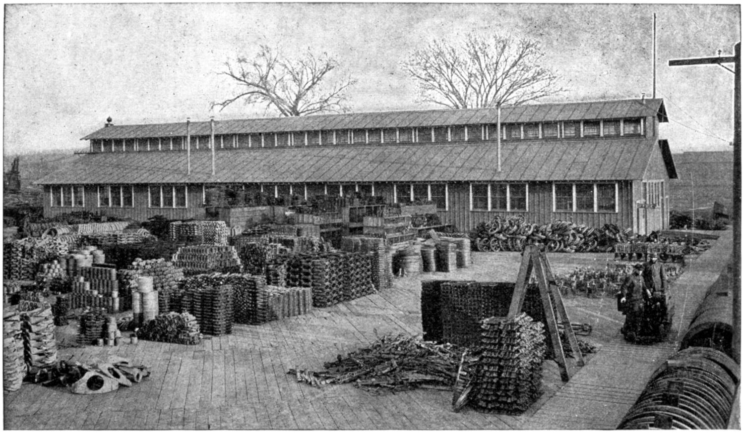
Welding School, Ordnance Department, United States Army, Peoria, Ill.
WILEY ENGINEERING SERIES
By
LIEUT. LORN CAMPBELL, JR., U.S.A.
Officer in Charge of Welding Instruction,
Ordnance Department, U. S. Army.
TOTAL ISSUE, FIVE THOUSAND
NEW YORK
JOHN WILEY & SONS, Inc.
London: CHAPMAN & HALL, Limited
1919
Copyright, 1919
BY
LORN CAMPBELL
Copyrighted in Great Britain
PRESS OF
BRAUNWORTH & CO.
BOOK MANUFACTURERS
BROOKLYN, N. Y.
[v]
(1) The oxy-acetylene method of welding and cutting metals has of late been receiving considerable attention. Its tremendous power of creating, repairing and destroying the work of man has been but recently recognized in its broadest sense, and the demand for operators, skilled in the manipulation of this apparatus, which always has been far in excess of the supply, now knows no limit. Many authorities have set forth their views and theories upon this subject, in America and also in foreign countries. These have been published from time to time in many of the leading periodicals and magazines, as well as in book form. It seems the purpose of most of these works has been to advance the operators who already have a smattering knowledge of this art, or to present to the purchaser of apparatus a set of operating instructions.
(2) It is singular indeed that a school manual, devoted exclusively to the instruction of the beginner, which will serve as an aid to the instructor as well as to the student, has not yet been put forth. It cannot be said that there is not a demand for such. Recently there seems to have been a mushroom growth of welding classes. The majority of the vocational schools, colleges, night schools, and automobile schools have all entered the instruction in oxy-acetylene welding on their rolls and each is attempting to instruct in an entirely different manner from the other.[vi] There can be no question as to the expediency of affording the educational institutions a systematic as well as a standardized method of instructing. But the books and articles of the nature mentioned are not suited to this purpose, and were not designed for it. A school-book is wanted; something to be used in the classroom, to be employed as a reference in the shop practice, to be studied for what it contains, and to indicate further lines of research, where such are required.
(3) To meet this demand, the present “Manual” has been written to serve the instructor as well as the student. In its preparation many books, both well-known and obscure, have been examined and the methods of shop instruction have been carefully studied by the author.
(4) It has been found that regardless of how fast the ground may be covered in the lecture room, the average student’s power of assimilation is limited and considerable time has been spent in determining this ratio and applying it between the lecture subjects and shop work.
(5) It must be remembered that while the chapters comprising the theoretical part of this welding manual follow in the order given, the actual shop practice, as previously mentioned, is the most important.
(6) Kindly aid has been received from many sources. Granjon & Rosemberg, Kautney, M. Keith Dunham, S. W. Miller, Henry Cave, C. J. Nyquist, P. F. Willis, Ben K. Smith, and others have embodied in their writings many excellent ideas, which have assisted the author in bringing out certain points advantageously. The following manufacturers are to be given credit for many of the illustrations:
The Oxweld Acetylene Co., Newark, N. J.
The United States Welding Co., Minneapolis, Minn.
The Bastian Blessing Co., Chicago, Ill.[vii]
The Linde Air Products Co., New York City.
The General Welding & Equipment Co., Boston, Mass.
The Messer Manufacturing Co., Philadelphia, Pa.
The Alexander Milburn Co., Baltimore, Maryland.
The Torchweld Equipment Co., Chicago, Ill.
The Davis-Bournonville Co., Jersey City, N. J.
The K. G. Welding Co., New York City.
The Chicago Eye Shield Co., Chicago, Ill.
The Commercial Acetylene Supply Co., New York City.
The Welding Engineer, Chicago, Ill.
The Journal of Acetylene Welding, Chicago, Ill.
Note.—Lieut. Campbell offers his services without charge to anyone interested in this method of welding and may be addressed care of John Wiley & Sons, Inc., Publishers, 432 Fourth Avenue, New York City.
[viii]
The Wiley Engineering Series will embrace books devoted to single subjects. The object of the Series is to place in the hands of the reader all the essential information regarding the particular subject in which he may be interested. Extraneous topics are excluded, and the contents of each book are confined to the field indicated by its title.
It has been considered advisable to make these books manuals of practice, rather than theoretical discussions of the subjects treated. The theory is fully discussed in text-books, hence the engineer who has previously mastered it there, is, as a rule, more interested in the practice. The Wiley Engineering Series therefore will present the most approved practice, with only such theoretical discussion as may be necessary to elucidate such practice.
[ix]
| PAGE | ||
| Introduction | 1 | |
| I. | Apparatus | 19 |
| II. | Operation | 27 |
| III. | Shop Equipment | 39 |
| IV. | Apparatus Repairs | 44 |
| V. | Preheating Agencies | 51 |
| VI. | Part One—Welding of Cast Iron | 58 |
| Part Two—Welding of Cast Iron | 67 | |
| Part Three—Welding of Cast Iron | 70 | |
| Part Four—Welding of Cast Iron | 75 | |
| VII. | Part One—Steel Welding | 81 |
| Part Two—Steel Welding | 87 | |
| Part Three—Steel Welding | 92 | |
| Part Four—Steel Welding | 97 | |
| VIII. | Brass Welding | 106 |
| IX. | Part One—Aluminum Welding | 109 |
| Part Two—Aluminum Welding | 113 | |
| Part Three—Aluminum Welding | 118 | |
| X. | Welding of Malleable Iron | 120 |
| XI. | Oxy-acetylene Cutting | 125 |
| XII. | Carbon Burning | 135 |
| Glossary | 145 | |
| Lectures | 149 | |
| Index | 167 | |
[1]
Oxy-Acetylene Welding Manual
(1) When choosing a life vocation, one generally views the possibilities it has to offer and delves deeply into these, previous to making a decision. It is therefore thought advisable at this time to present the student with an idea of what is meant by oxy-acetylene welding and cutting; how it is applied; the possibilities and advantages attached to such an art.
(2) Acetylene gas, when burned with a proper portion
of oxygen gas, produces an extremely hot flame, in fact,
the hottest flame known. Its temperature is over 6000
degrees Fahrenheit. With this flame it is possible to bring
any of the so-called commercial metals, namely: cast iron,
steel, copper, and aluminum, to a molten state and cause
a fusion of two pieces of like metals in such a manner that
the point of fusion will very closely approach the strength
of the metal fused. If more metal of like nature is added,
the union is made even stronger than the original. This
method is called oxy-acetylene welding and differs from
what the average layman considers welding in the blacksmith’s
forge, insomuch that there is no blow struck to
assist fusion in this process. And while the forge method
is limited to wrought iron and steel which is detachable[2-
3]
and of restricted size and shape, the oxy-acetylene process
has, practically speaking, no such limitations.
(Courtesy of Acetylene Journal Publishing Co.)
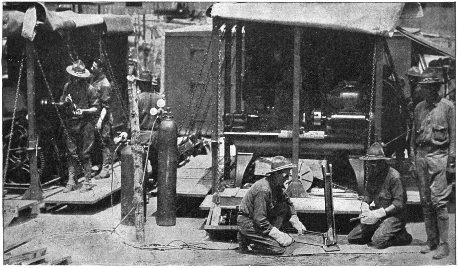
Fig. 1.—Welders on an Ordnance Mobile Repair Unit in Action.
(Courtesy of the Oxweld Acetylene Co.)
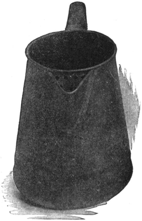
Fig. 2.—In Enameled Products for the Kitchen the Weld is Fast Replacing the Riveting, Brazing, and Soldering of the Light Sheet Metal Seams.
(3) Manufacturers in the metal-working world were very slow to grasp the real significance of this important process, until the operators began demonstrating some of its possibilities. At the present time, however, there is hardly a metal barrel or tank manufacturer who has not discarded the old method of producing costly leaky, riveted drums and containers, for this modern fusing process. The manufacturers of fire-proof doors and windows, cooking utensils, seamless pipe and tubing, office furniture and what not, are now virtually dependent upon the welding torch at every turn.
(4) As a repairing agent, the welding torch has no rival. Whether it is a casting of iron, steel, brass, or aluminum that has broken; a boiler or tank that has worn away in spots, or an error on the part of engineer, foundryman or machinist, the part can generally be reclaimed and made stronger than originally. To-day practically no manufacturing concern that is dependent upon metallic machinery could think of being deprived of its oxy-acetylene apparatus, once having learned its worth. In the not far distant past, were a gear or some casting to break, it probably meant closing[4] down the entire plant until a new part could be obtained, which, whether the source of supply were near or at a long distance, would mean costly delay. With oxy-acetylene equipment and an efficient operator on hand, almost every emergency is provided for.
(Courtesy of the Oxweld Acetylene Co.)
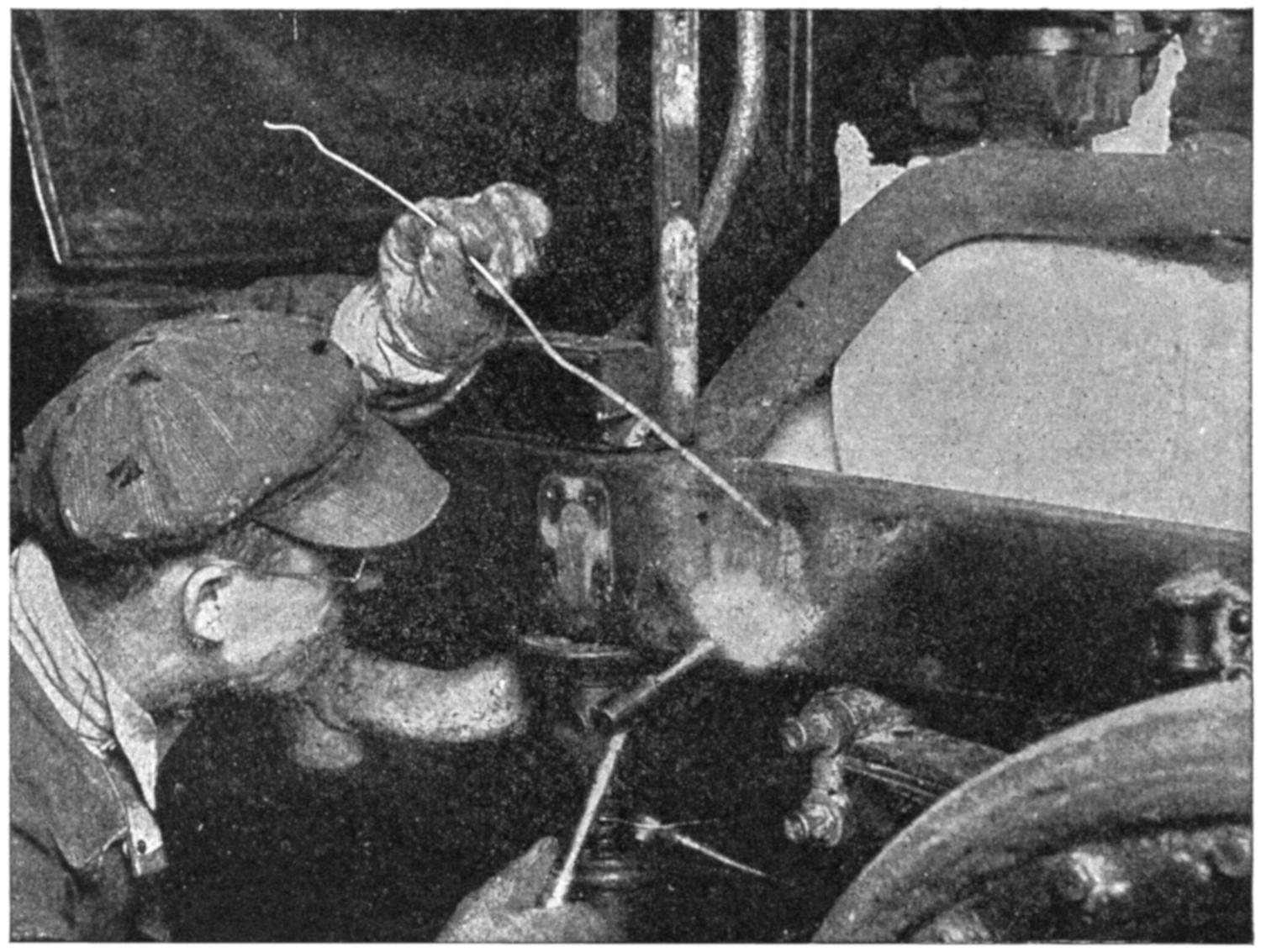
Fig. 3.—Welding Broken Frame of 5-ton Automobile Truck.
(5) If an automobile owner breaks a frame, he does not consider replacing it with a new one, as the labor alone for stripping his machine and setting it up again, not to mention the cost of the new frame and the time required for this operation, is prohibitive. Rather, he has his car taken to the nearest welder or his portable apparatus to the car and the job is completed within thirty or forty minutes, with the frame at the point of the break made stronger than ever. Locomotive frames are handled in much the[5] same manner, only more time is required and perhaps extra operators, but the important point to be brought out is the fact that on many jobs no dismantling is required and the repair is permanently and quickly executed.
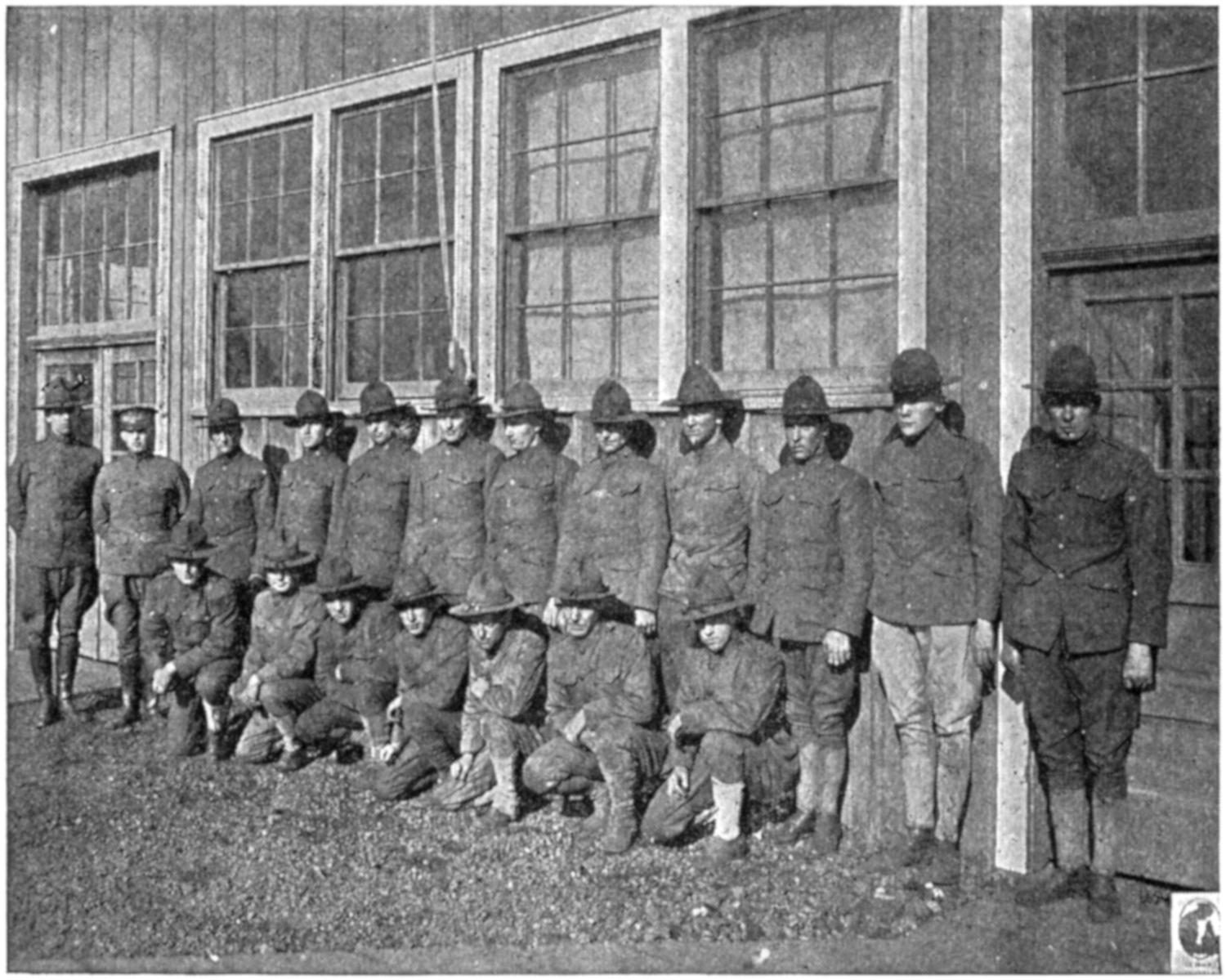
Fig. 4.—Staff of Instructors at the Ordnance Welding School, U. S. A.
(6) An interesting example of the true worth of welding was brought to the attention of the public when the United States entered the European War, and all the interned German vessels, which had been greatly damaged by the orders of their commanding officers, were restored to working condition with the oxy-acetylene and electric welding process. This was considered impossible by many engineers not familiar with the process, insomuch as they looked upon oxy-acetylene welding as applicable only to small parts and[6] here some of the sections which had been blown or struck out of the cast cylinders, etc., weighed many hundreds of pounds. In many instances the ribs of these same vessels were cut most of their depth, but these were restored to working order in a remarkably short time and the results were more convincing than any words.
(7) Cutting with the oxy-acetylene process is just the opposite from that of welding. The latter might be considered constructive and the former destructive. In the case of welding, two parts are brought to a molten condition along the line to be joined and both fused together. Whereas in cutting, one piece of metal, when brought to a red heat, is cut in two by an oxidizing flame. Cutting has not the wide scope that welding has, for it can only be applied successfully at the present day to wrought iron, rolled and cast steel. While it is limited in its scope, the speed of this process in severing large masses of metal is very spectacular and appeals forcibly to the observer.
(8) Probably the world’s first awakening to the real meaning of oxy-acetylene cutting came when the U. S. battleship “Maine,” was being taken from Havana Harbor. All the heavy armor plate and seemingly immovable wreckage was cut into small sections which could be handled easily. This was all accomplished with the cutting torch, which seems to eat its way through metal with the same ease that a hot knife goes through butter.
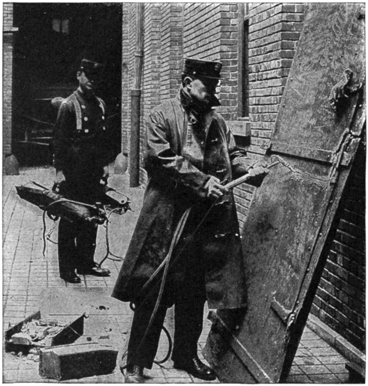
(Courtesy of the Oxweld Acetylene Co.)
Fig. 5.—Fireman Cutting ¹⁄₄-inch Steel Fire Door with Portable Apparatus.
(9) Before and since the time of the “Maine,” the cutting torch has been accomplishing wonderful feats. In every scrap yard, old boilers and the like are being cut into furnace size; speeding up the production in answer to the world’s cry for more metal. The wreckage on railroads and buildings using steel reinforcements is being cleared in hours, with the aid of the cutting torch, where it required days by other methods. Most of the fire departments in[7] the larger cities now carry the cutting torch as part of their equipment, and to it has been credited the saving of many lives, by its timely cutting away of steel doors, bars or barriers which prevented escape. Much of the plate in this country’s shipbuilding yards is being cut to size right on the job, and the function of this torch in cutting off risers measuring from one to thirty-six inches in diameter in the foundry seems only to be of secondary importance in comparison with[8] some of its other uses. In order to transport some of the largest inland lake boats which were much too long to pass through the locks, to the sea, they were cut in parts, transported, and later welded together and placed in service.
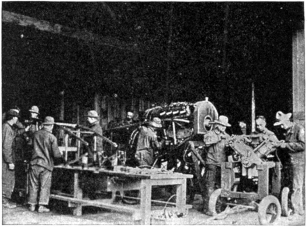
(Courtesy of the Acetylene Journal Publishing Co.)
Fig. 6.—Welders of the Signal Corps, U. S. Army, in Action.
(10) It is not only possible to keep a cutting torch burning under water, but it can also be made to cut. Contracting companies are cutting off their piling under water and it has been known that in European ports cutting has been successfully accomplished at a depth of thirty feet. A special torch is employed by submarines to cut nets under water.
(11) In reviewing the oxy-acetylene welding and cutting process, we find that its growth is one of the most remarkable the world has ever witnessed. About 1907 saw its industrial birth and since that time it has advanced by leaps and bounds, rivaling the automobile industry in its progress,[9] despite the opposition and criticism levied at it by workers of other trades and its careless and unskilled manipulation.
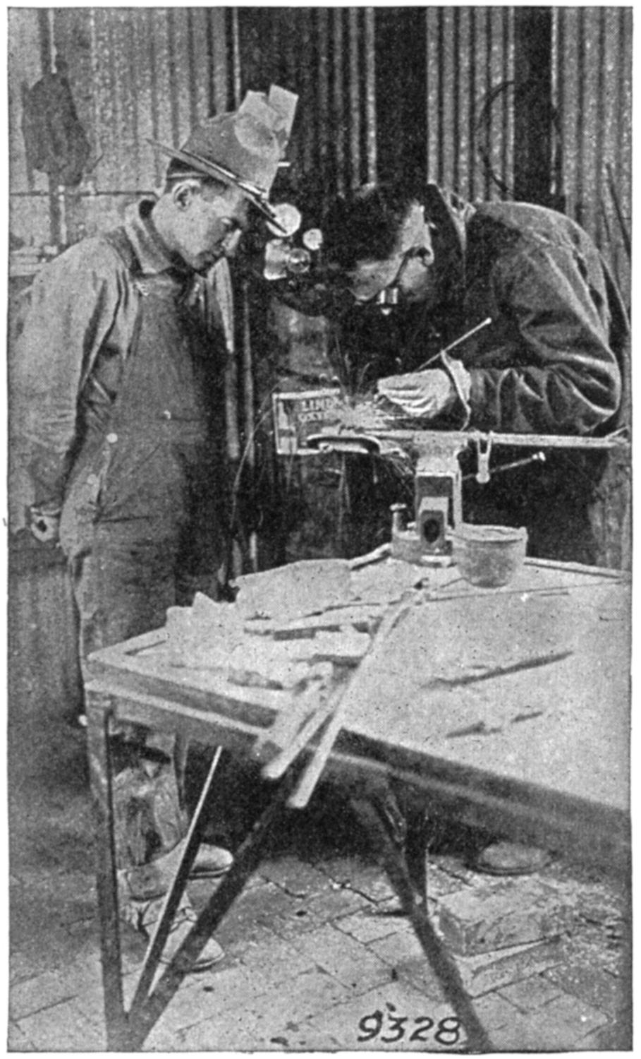
(Courtesy of the Acetylene Journal Publishing Co.)
Fig. 6a.—Welders of the Signal Corps, U. S. Army, in Action.
(12) It is quite impossible to present anything like a complete list of the applications of this process, but a few of its general uses are here enumerated:
(A) Airplane Construction.—Welding of frames, sockets, water and gasoline tanks, water jackets and valve cages to[10] cylinders, intake and exhaust manifolds and connections, spark plug thimbles and the repair of aluminum crank cases, etc.
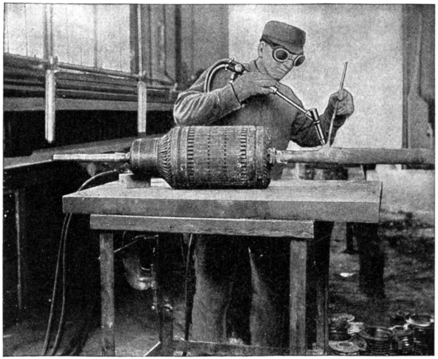
(Courtesy of the Oxweld Acetylene Co.)
Fig. 7.—Welding a 2-foot Length of New Shafting on the End of a Motor Shaft 2 Inches in Diameter.
(B) Automobile Manufacture.—Welding of steel and aluminum bodies, transmission and rear axle housings, crank-shafts, cylinders, gears, manifolds, pinions, crank cases, valves, rims, mufflers, frames, fenders, wind-shield tubings, and uprights, etc.
(C) Boiler Shops.—Welding and building up worn spots around hand-hold plates, repairing cracks and checked portions of fire boxes, retipping flues, connections, etc.
(D) Brass and Copper.—Welding kettles, vats, tanks,[11] stills, floats, cooking utensils, manifolds, water jackets, electrical and chemical wares, etc.
(E) Commercial Welding.—Reclamation service on all kinds of metals, quick and permanent repairs on all broken parts of machinery.
(F) Electric Railway.—Welding air receivers on air-brake systems, building up shafts, bonding the rails, motor housings, worn boxes, reclaiming gears and broken trucks, steel trolley wires, etc.
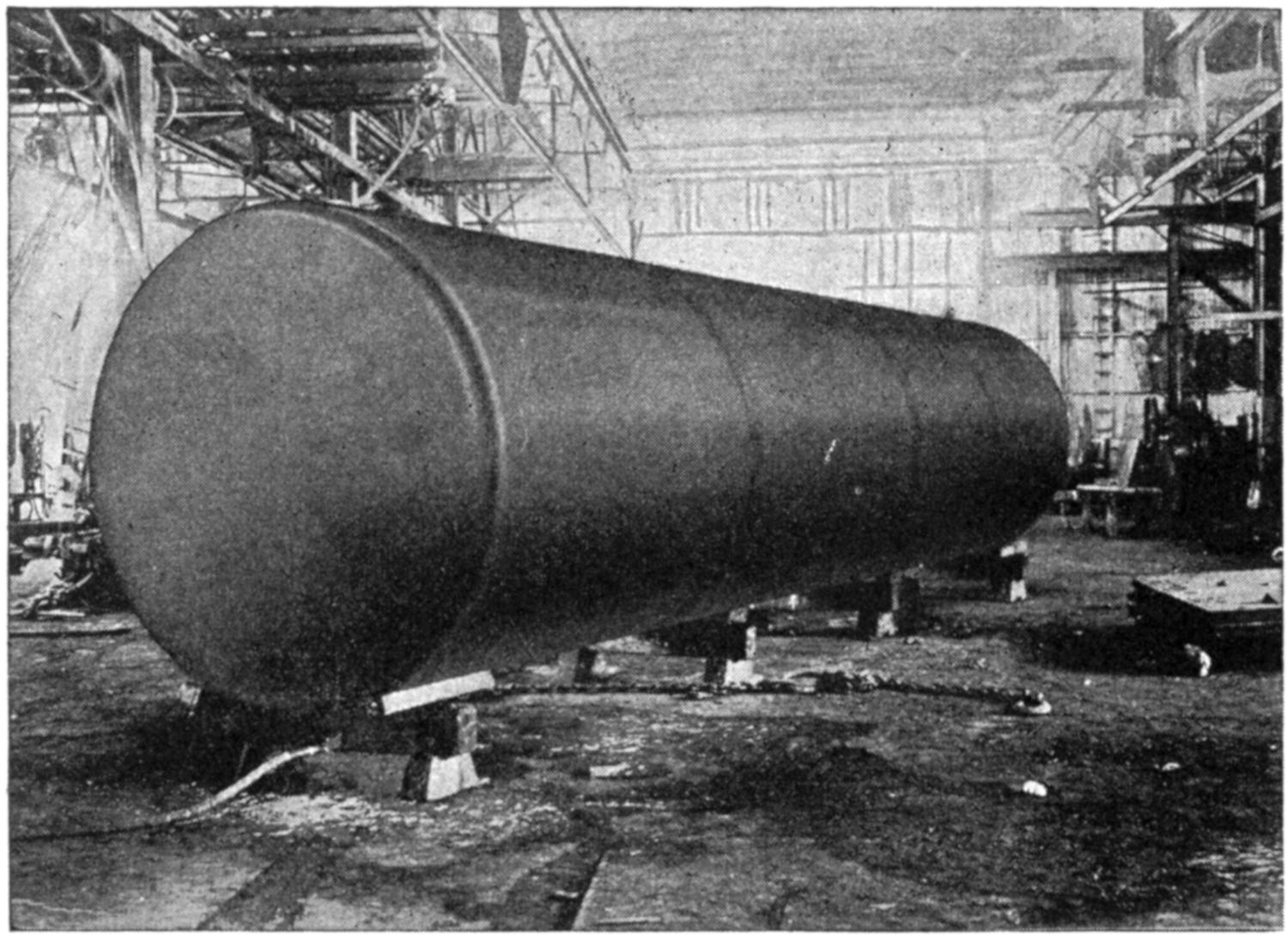
(Courtesy of the Torchweld Equipment Co.)
Fig. 8.—This is a Steel Tank, Made of ³⁄₈-inch Plate, which Measures 30 Feet Long and 8 Feet in Diameter, Fused into One Piece by the Welding Torch.
(G) Forge Shop.—Welding complicated parts which can not be conveniently handled in the forge.
(H) Foundries.—Welding up blowholes, porous spots, and reclaiming castings in general. The cutting off of risers, gates, and heads on steel castings.
[12]
(I) Lead Burning.—Lead pipe joints, storage battery connections and repairs, lead linings in vats, etc.
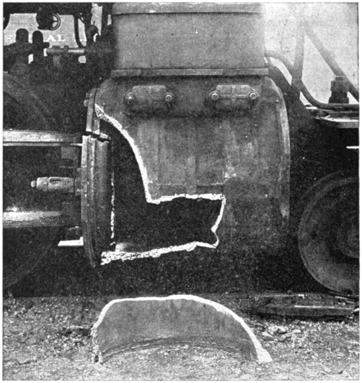
(Courtesy of Ben K. Smith, U. S. Welding Co.)
Fig. 9.—Locomotive Cylinder to be Welded in Place.
(J) Lumber Mills.—Building up worn shafts, repairing gears, chains, and broken parts.
(K) Machine Shops.—Rectifying errors on part of machinists and engineers. A “putting-on” tool in every respect.
(L) Manufacturers.—Welding spouts and handles on[13] cooking utensils, fire-proof doors and window sashes, office files and furniture, chains, etc.
(M) Mines.—Repairing pipe lines, boilers, broken shafts, gears, and building up worn parts on dippers, etc. The cutting torch is used for clearing away wreckage in case of accidents.
(N) Pipe Work.—Welding of water, gas, and oil, steam and air lines. High-pressure refrigeration systems are cut and welded in place.
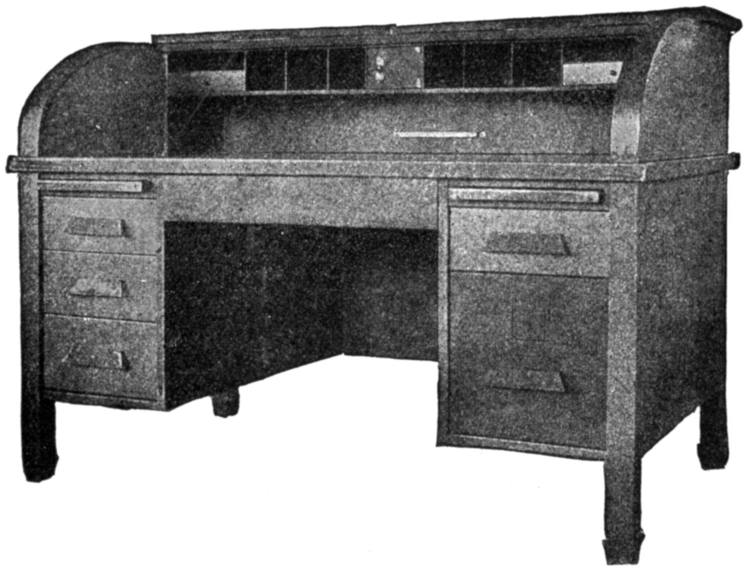
(Courtesy of the Oxweld Acetylene Co.)
Fig. 10.—Steel Roll Top Desk—all Joints and Seams Welded. An Excellent Example of High-grade Welded Metal Furniture.
(O) Plate Welding.—Tanks for oil, steam driers, digesters, vats, chemical receivers, generators, etc.
(P) Power Plants.—Welding of steam, air, and water-lines, of pump castings, cylinders, pistons, worn or broken parts, etc.
(Q) Railroad Work.—Reclaiming bolsters, couplings, slotting[14] forged engine rods, building metal cars, repairing fire-boxes, patching and replacing side sheets, flue welding, building up frogs and crossings, cutting off rails, mud rings, welding cracked cylinders, cross-heads, steam-chests, building up worn spots on wheels, rims and pins, welding spokes and locomotive frames, etc.
(Courtesy of the Oxweld Acetylene Co.)
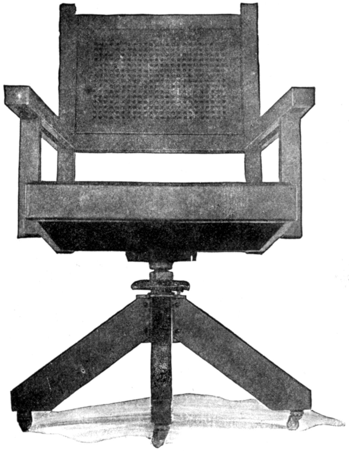
Fig. 11.—Office Chair. Welded at all Joints.
(R) Rolling Mills.—Fabricating “open-hearth,” water jacket doors, cutting up “lost heats,” scrap plates and bar stock billets. General repairs of furnace equipment, hot beds, rolls, gears, engines, plates, etc.
[15]
(S) Sheet Metal.—Manufacture of tubing, oil-storage barrels, metallic furniture, range boilers, etc.
(T) Shipyards.—Cutting off plates and irregular shapes of steel, channels, special sections. Building up of worn shocks, building and patching hulls, stringers and the reclamation of propellers, posts and broken parts of machinery, etc.
(U) Structural Steel.—Cutting holes for rivets, gussets and splice plates, and wrecking. Welding up misdrilled holes and machinist’s errors. Cutting channels, I beams, and other shapes for coping, splicing and fitting rails, welding reinforcing rods for concrete work of any desired length and structural parts where bolting and riveting is difficult or impossible.
(Courtesy of the British Oxygen Co.)
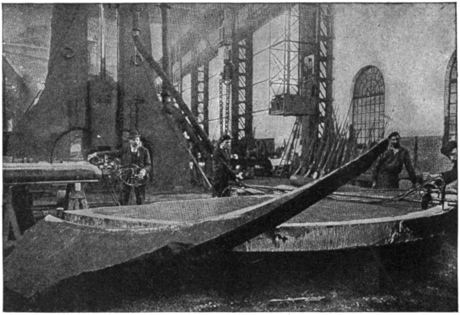
Fig. 12.—Cutting Armor Plate by the Oxy-acetylene Process.
(V) Scrap Yards.—Cutting up scrap boilers, tanks and other large work to mill size, wrecking structural buildings, and reducing to small size, reservoirs, tanks and boilers,[16] which are housed in buildings to remove them without damage to the structures.
(W) Tractor Industry.—Cutting and welding frames, track and wheel guards, water, gasoline, and oil tanks; welding up of blowholes, porous spots and misdrilled holes in castings of all kinds.
(Courtesy of the Davis-Bournonville Co.)
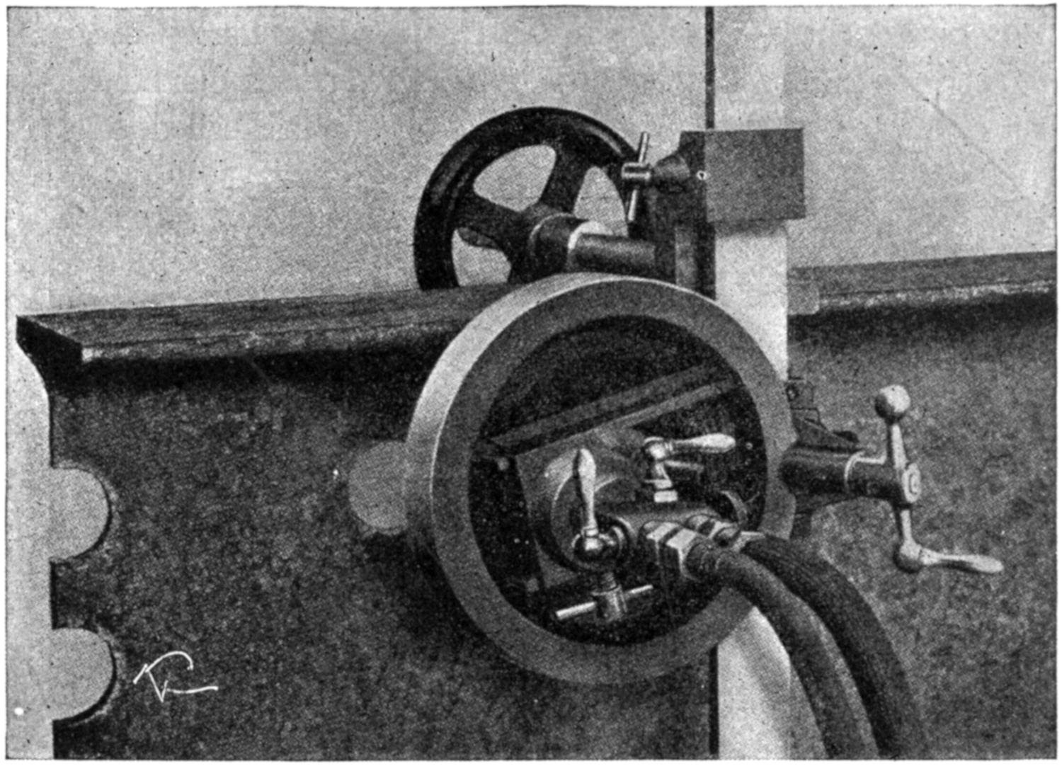
Fig. 13.—Here is Illustrated an Oxy-acetylene Machine for Cutting Holes in the Web of Rails, or in Structural Iron, of not more than ³⁄₄ Inch in Thickness. It can be Quickly Attached and Accurately Adjusted to Pierce through the Iron Instantly, without any Previous Drilling, and it will Cut Smooth Round Holes, from ¹⁄₂ to 2 Inches in Diameter in from 30 to 60 Seconds. It is Particularly Adapted for Railroad Work, and Enlarging or Cutting Holes in Building and Bridge Work.
(13) The foregoing, as previously stated, is but a partial list of some of the applications of the oxy-acetylene welding and cutting process to various industries. What has the[17] future in store for it? Almost daily, some new application is found for it and at the present time experiments are under way in boiler construction, the results of which are not difficult to foresee. Giant hulls of seagoing vessels are being fused together by welding and the limits of this wonderful process which is now practically in its infancy are difficult to forecast.
(14) During the World War many manufacturers of non-essentials shut down and others turned their entire production over to the government, changing their machinery and in most instances their entire plant. What, then, are those who are operating machines and apparatus, produced by these firms before the war, going to do for replacements? There is but one answer, have their broken or worn out parts welded.
(15) Oxy-acetylene operators have always numbered far less than the demand, a point which was clearly brought out by the government when its immense Army and Navy were being formed. There were so few men familiar with the oxy-acetylene process that it at once took measures to establish its own schools where men could be trained, a thing that the commercial world had been THINKING of doing for some years. As the demand for operators continues to increase, it behooves a man, even though he is not a metal worker, to think and apply himself, in order that he may “carry on,” to the best advantage when opportunity knocks.
(16) The methods of instruction herein set forth are very simple and while differing in many respects from those used by the trade, have been most successfully employed in producing efficient operators. Certain principles are instilled in the beginner and some of the exceptions which are of minor importance are overlooked to avoid confusion. Criticism is expected from those who have never engaged[18] in instruction of this kind on a large scale. There are many differences to be expected on account of this very fact, for there are few who have gone further than the instruction of very small classes where individual attention may be given.
(17) All history of the process, gas manufacture and the like have been omitted in order to give greater detail to the actual shop practice and to have the operator become familiar with his apparatus and thereby operate it with all due respect and intelligence.
(18) Oxy-acetylene welding cannot be learned by watching others work, although observation may at times assist the beginner. Actual torch practice, brain work and a power of “I will,” produce the most efficient operators. For those who earnestly apply themselves to the instructions which follow, there is every reason to believe that success will be theirs.
[19]
(19) Welding apparatus in general consists of two regulators equipped with pressure gauges, two lengths of hose, and a welding torch. The regulators are attached to cylinders of acetylene and oxygen and are used to reduce and maintain a uniform pressure of these gases for use at the torch. The gases at reduced pressure are conveyed to the torch by the hoses. The regulators should each have a high-pressure gauge to indicate the contents of the cylinder, and also a line or working-pressure gauge to show the gas pressure on each hose. When the gases reach the torch they are there mixed and combustion takes place at the welding tip, which is fitted to the torch. Such an apparatus is called portable, on account of its movability. There are other equipments wherein one or both of the gases are generated, but these will not be discussed here.
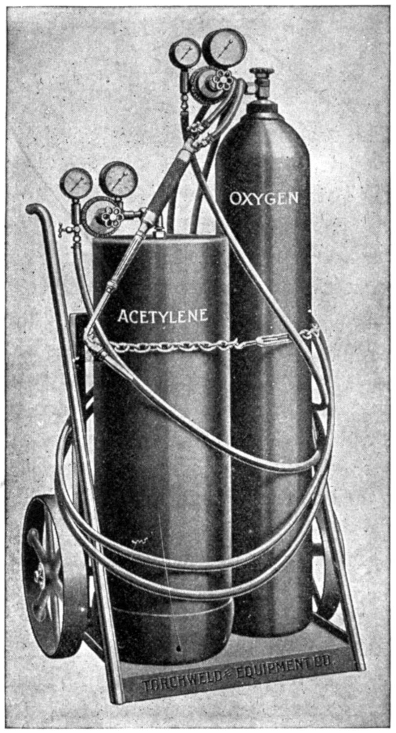
Fig. 14.—A Portable Welding Unit.
(20) For convenience oxy-acetylene welding apparatus may be divided into three classes, depending upon the principles used in securing the fuel gas or acetylene for the flame. Low-pressure, medium-pressure and high-pressure apparatus generally use about the same pressure of oxygen and it will be called a constant. The acetylene gas is a variable and in the low-pressure type only enough pressure is required to overcome the friction of the line until it reaches the oxygen injector, located in the torch, which acts as a syphon, drawing the acetylene gas to the point of ignition. In a medium-pressure type about three-fourths as much pressure[20] is required on the acetylene line as on the oxygen. This type is apt to verge on the injector type, as it depends to some extent upon the oxygen under pressure carrying acetylene gas to the point of ignition. In the high-pressure type equal pressure on each line is used. To further make this classification clear, a certain sized tip using, perhaps, 12[21] pounds of oxygen pressure can be used as an example. In a low-pressure type perhaps 2 pounds pressure or less will be needed on the acetylene line. On the medium-pressure approximately 9 pounds will be required, while on the high-pressure an equal amount, or 12 pounds will be needed.
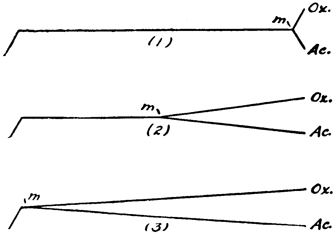
Fig. 15.—Location of Mixing Chambers in Welding Torches.
(1) Shows gases mixing in the handle. (2) Has the mixing chamber in the middle of the torch. (3) Illustrates how the gases are kept separate until the head of the torch is reached. Ox. represents oxygen gas; Ac. acetylene gas; and m mixing chamber.
(21) The mixing chambers for the gases may be located in the head; in the middle of the torch, or in the handle. By mixing chambers reference is made to that portion of the torch where the two gases are brought together and mixed. As can be seen with three different types of welding torches and three different locations for the mixing of the gases, the manufacturers can find a large range for producing oxy-acetylene apparatus. Some undoubtedly will fill certain requirements better than others. Much, too, will depend upon the ability of the operator in handling a torch.
(22) Flashbacks are caused by the improper mixture of the gases, which increases the rate of flame propagation to such an extent that the flame will flash back to the mixing chamber. Acetylene in a pure state will burn very much slower than when mixed with equal parts of oxygen. When[22] more oxygen is introduced the flame propagation is much greater, so that when an excess of oxygen is used, there is bound to be considerable trouble from backflashing. When sufficient acetylene is introduced to the mixing chamber, there is absolutely no chance for this lean mixture to occur. If the flame flashes back to the mixing chamber, both gases should be closed off immediately, at the torch, the oxygen first, and then the acetylene gas.
(23) In some torches the heating of the mixing chamber will cause a flashback and with these it is necessary to shut off the acetylene and leave the oxygen valve just cracked and immerse the torch head in water, dipping it slowly, so as not to cause too great a strain. The oxygen will bubble out and prevent the water backing up in the tip. If the flashback deposits enough soot on the inside of the tip and the head to impair the working quality of the torch, the soot should be removed by using a soft wire, preferably of copper, or some other material which will not mar the tip.
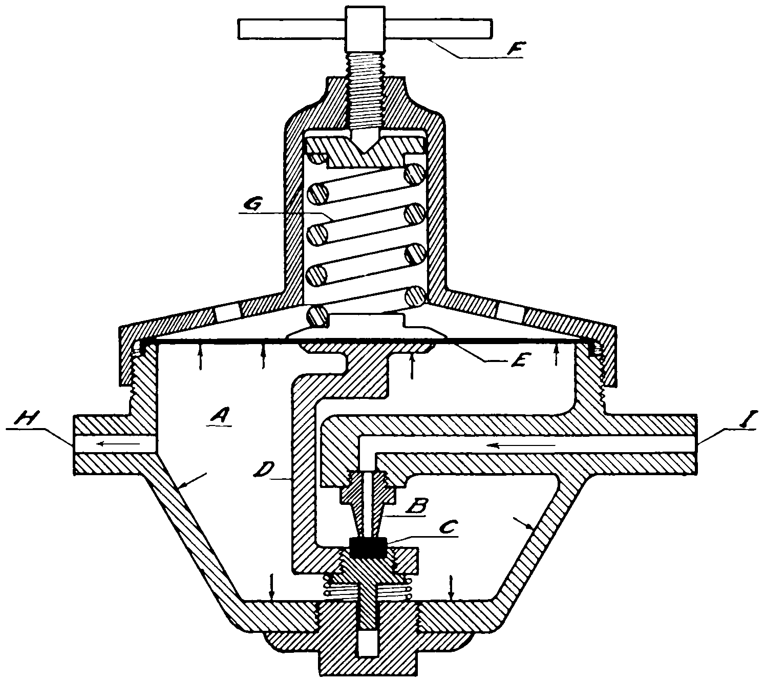
Fig. 16.—Cross-section of Regulator.
A, chamber; B, nozzle; C, seat; D, seat arm; E, diaphragm; F, cross-bar, or adjusting screw; G, diaphragm springs; H, gas outlet; I, gas inlet.
(24) It is interesting to note the action of a regulator, used to reduce the cylinder pressure on both gases. The gas from the cylinder, at high pressure, comes directly into the body of the regulator or chamber (A), Fig. 16, through a fine nozzle (B). A seat of gallilith, casenite, or fiber (C), attached to an arm (D), presses against this nozzle. Arm (D), in turn, is attached to a very sensitive diaphragm (E) and is moved every time there is a pressure exerted on the latter. The movement of this diaphragm is controlled by a handle or a screw, with a “cross-bar” attached to its end as is shown at (F). This screw bears upon the diaphragm through the medium of the springs (G). As this screw is forced inward the springs force the diaphragm in, and thereby move the seat away from the nozzle of the regulator. The gas, entering under high pressure, exerts an equal force on all parts of the chamber and the diaphragm[23] receives its share. Now the chamber walls are made of a solid material, usually a bronze or brass, and cannot be changed, but this diaphragm can be moved and as this pressure is increased, the diaphragm is forced out and the nozzle (B) is automatically closed by having the seat (C) brought in contact with it. When gas is drawn off through the line (H), the pressure within the chamber will naturally drop and as it does so, the springs will force the diaphragm inward, permitting a replacement of the gas drawn off. Although not noticeable, there is a continual movement of this diaphragm whenever the gas is being used. It can be readily seen that the amount of pressure within the regulator can be accurately set by the tension of the spring against the diaphragm which is controlled by the screw carrying the “cross-bar.”
[24]
(25) There are two types of regulators manufactured for the reduction of gases under high pressure, depending upon the nature of work to be done. The high-pressure regulator is employed for heavy work where a great deal of gas is used and the regulator must pass it without much effort, to prevent its freezing. This type of regulator is used on cutting or on large welding work. It differs from the low-pressure or ordinary type in four distinct features. Generally it contains a much heavier diaphragm which is smaller in diameter, making it stiffer in every respect. The tension springs which act upon this diaphragm are much heavier. The nozzle which presses against the seat is much larger, to permit the passage of a greater amount of gas. Then, too, a larger working pressure gauge must be used, in order to read this high pressure. In the welding of metals, especially in steel, the adjustment of the flame is a very important matter, and absolutely dependable regulation must be had. This is not possible with a high-pressure regulator and is not intended to be so. The larger the diaphragm, the more sensitive the regulator, and this point should be borne in mind, and no small welding work attempted with the high-pressure regulator. The reverse form of reasoning may be applied to low-pressure regulators which have been used in cutting. They are very likely to be strained and satisfactory results cannot be expected, for they are not made for that purpose. Acetylene regulators are constructed much more sensitively than the oxygen regulators, to take care of the lower pressure of gas and in a sense might be called weaker, insomuch that the larger nozzle which passes the gas is closed or regulated by springs which are not nearly as strong as in the oxygen regulator. For this reason acetylene regulators cannot be interchanged with oxygen regulators for they will not stand the pressure demanded in the first place, and in the second place, were a small quantity of[25] acetylene gas left in the regulator and oxygen introduced, an inflammable mixture would be formed which is not advisable to have present, on account of its explosiveness. In many instances oxygen regulators are put out with the copper diaphragms, whereas another metal must be used on the acetylene regulators, because acetylene gas attacks copper and usually a German silver or rubber diaphragm is used. On account of the lower pressures used in charging the acetylene cylinders, lower pressure gauges are used than on oxygen regulators.
(26) All tension should be removed from the diaphragm springs by screwing out on the “cross-bar” (that is, to the left), before admitting gas under pressure to the regulator to avoid abusing the seat. If a matter of 1800 pounds pressure were admitted suddenly into any regulator that had the seat removed from the nozzle, there would be a sudden exertion upon the diaphragm, which would draw the regulator seat up very violently against the nozzle, and if it did not crack the seat it would undoubtedly groove it to such an extent that it would leak and a trouble known as “creeping regulator” would result. If this occurs, good work cannot be expected because the flame will not remain steady, and it is therefore necessary to take steps to rectify this abuse. If there is a welding company available, the regulator should be sent to it for repairs, but if the operator is in an isolated district when this occurs, and must have some means of continuing work, it will be possible for him to remove the seat by unscrewing the back of the regulator. If the seat has become grooved, and he thinks that this is the trouble, many times the seat can be turned over and the machined surface on the other side used. If the seat is cracked, however, about the quickest way of making an emergency repair is to turn out a new seat from hard rubber or fiber on a lathe.
[26]
(27) In acetylene cylinders an absorbent called acetone is generally used, which gives up the gas as required. A full cylinder can be used for some time without any noticeable difference in the gauge reading, and then, as it nears the empty point, the gauge reading will drop very perceptibly. It is therefore impossible to depend upon a high-pressure acetylene gauge as an index to the contents of the cylinder. The only method known to correctly check the amount of acetylene gas on hand is to weigh the cylinder. There are 14¹⁄₂ cubic feet of acetylene gas to the pound, and when the net weight of the cylinder is given the contents can readily be figured. A tag bearing the net weight or figures which will permit its computation is generally found attached to each acetylene cylinder. In the case of oxygen cylinders, there being no absorbent used, the contents of the cylinder is indicated on the high-pressure gauge. On the latest type gauge the contents will be shown by cubic feet, by pounds pressure and by atmospheric pressure, to facilitate the computation of costs by the operator.
(28) Occasionally a needle valve on a torch will begin to leak and it will be found necessary to grind it. Realizing that oil and grease are not to be used where oxygen is in evidence, the question is often brought up as to the proper lubricant to be used in doing this kind of work. Glycerine is used by most manufacturers, together with powdered glass or flour emery. In doing work of this kind the finished job is thoroughly washed with ether. Occasionally when piping oxygen lines through the shop, a screwed coupling will leak and there is a temptation to calk the same with white lead, but this should never be done, rather use lead oxide mixed with the glycerine for this purpose as it forms a paste which sets very rapidly and forms a hard, tough compound.
[27]
(29) In oxy-acetylene welding there are two gases used, as the name would indicate, namely, oxygen and acetylene. The first is used to intensify the flame and can in nowise be likened to the inflammable nature of the second. There is a great deal of oxygen present in the air we breathe. It is an odorless, tasteless, and colorless gas, as most of us are aware. In the commercial world oxygen is manufactured by the decomposition of water into its elements, oxygen and hydrogen, by the electrolytic process or is taken from the air by a reduction process and is stored in steel-drawn cylinders. These cylinders are drawn out of one piece of steel and are of considerable thickness throughout, having absolutely no seams, welded or otherwise. There is no filler nor absorbent used on the inside of these cylinders, as pure oxygen under pressure is not considered dangerous. The standardized sized oxygen cylinder is one which contains 200 cubic feet of gas fully charged. Oxygen is compressed in these cylinders at a pressure of 1800 pounds, at normal temperature, and this pressure does not vary to any great extent with change in temperature (as shown by table on page 29). There is attached to the tip of the steel cylinder, or “bottle,” as some workers call it, a double seating valve which has one seat operate when the cylinder is closed, and the other when the cylinder is wide open. A regulator is attached to this valve when working.
[28]

Fig. 17.—Sectional View of Oxygen Cylinder without Valve.

(Courtesy of the Linde Air Products Co.)
Fig. 18.—A Standard 200-foot Oxygen Cylinder.
[29]
TABLE SHOWING THE DIFFERENT PRESSURES OF OXYGEN—AT VARIOUS TEMPERATURES
| Temp. Deg. Fahr. |
Press. Lb. Per Deg. |
Temp. Deg. Fahr. |
Press. Lb. Per Deg. |
Temp. Deg. Fahr. |
Press. Lb. Per Deg. |
Temp. Deg. Fahr. |
Press. Lb. Per Deg. |
|---|---|---|---|---|---|---|---|
| 0 | 1568 | 25 | 1654 | 50 | 1739 | 75 | 1824 |
| 1 | 1572 | 26 | 1657 | 51 | 1743 | 76 | 1828 |
| 2 | 1575 | 27 | 1660 | 52 | 1746 | 77 | 1831 |
| 3 | 1579 | 28 | 1664 | 53 | 1749 | 78 | 1835 |
| 4 | 1582 | 29 | 1667 | 54 | 1753 | 79 | 1838 |
| 5 | 1585 | 30 | 1671 | 55 | 1756 | 80 | 1842 |
| 6 | 1589 | 31 | 1674 | 56 | 1760 | 81 | 1845 |
| 7 | 1592 | 32 | 1678 | 57 | 1763 | 82 | 1848 |
| 8 | 1596 | 33 | 1681 | 58 | 1766 | 83 | 1852 |
| 9 | 1599 | 34 | 1684 | 59 | 1770 | 84 | 1855 |
| 10 | 1603 | 35 | 1688 | 60 | 1773 | 85 | 1859 |
| 11 | 1606 | 36 | 1691 | 61 | 1777 | 86 | 1862 |
| 12 | 1609 | 37 | 1695 | 62 | 1780 | 87 | 1865 |
| 13 | 1613 | 38 | 1698 | 63 | 1784 | 88 | 1869 |
| 14 | 1616 | 39 | 1701 | 64 | 1787 | 89 | 1872 |
| 15 | 1620 | 40 | 1705 | 65 | 1790 | 90 | 1876 |
| 16 | 1623 | 41 | 1708 | 66 | 1794 | 91 | 1879 |
| 17 | 1626 | 42 | 1712 | 67 | 1797 | 92 | 1883 |
| 18 | 1630 | 43 | 1715 | 68 | 1800 | 93 | 1886 |
| 19 | 1633 | 44 | 1719 | 69 | 1803 | 94 | 1889 |
| 20 | 1637 | 45 | 1722 | 70 | 1807 | 95 | 1893 |
| 21 | 1640 | 46 | 1725 | 71 | 1811 | 96 | 1895 |
| 22 | 1643 | 47 | 1729 | 72 | 1814 | 97 | 1900 |
| 23 | 1647 | 48 | 1732 | 73 | 1818 | 98 | 1903 |
| 24 | 1650 | 49 | 1736 | 74 | 1821 | 99 | 1906 |
| 100 | 1910 |
Fig. 19.
(30) Acetylene is the fuel gas, and is one of the greatest containers of heat known. Burning in a free state, its carbon content is so rich that complete combustion is impossible, and stringy black particles will be noticed floating through the air. In order to fully combust this gas, oxygen is introduced under pressure and a temperature of over[30] 6000 degrees Fahrenheit is obtained. (Acetylene contains about five times as many B. T. U.’s (British Thermal Units) as hydrogen.) This gas, unlike oxygen, becomes very dangerous when in a free state it is subjected to an excessive pressure. The slightest jar may cause its disintegration and a violent explosion follows. On account of this danger, acetylene is not stored in a free state; neither is it subjected to very high pressures. Its cylinders are put[31] out by various manufacturers to comply with the laws and regulations of the Interstate Commerce Commission. Some of these cylinders have been welded, but the most modern method is to make them of one piece of drawn steel. They are then filled with an absorbent of some kind to take up the gas and prevent any portion of it being left in a free state. Acetone is the popular absorbent, and is a liquid capable of absorbing twenty-five times its own volume of acetylene gas at normal pressure. The filling material varies with each of the manufacturers, but charcoal, asbestos and mineral wool are in very common use. Acetylene is obtained from calcium carbide brought in contact with water, or vice versa, and is compressed and then stored in the cylinders at a pressure varying from 150 to 250 pounds. When fully charged this pressure will vary almost directly with any change of temperature. Acetylene cylinders for welding are available in 100, 200, 225, and 300 cubic foot sizes.
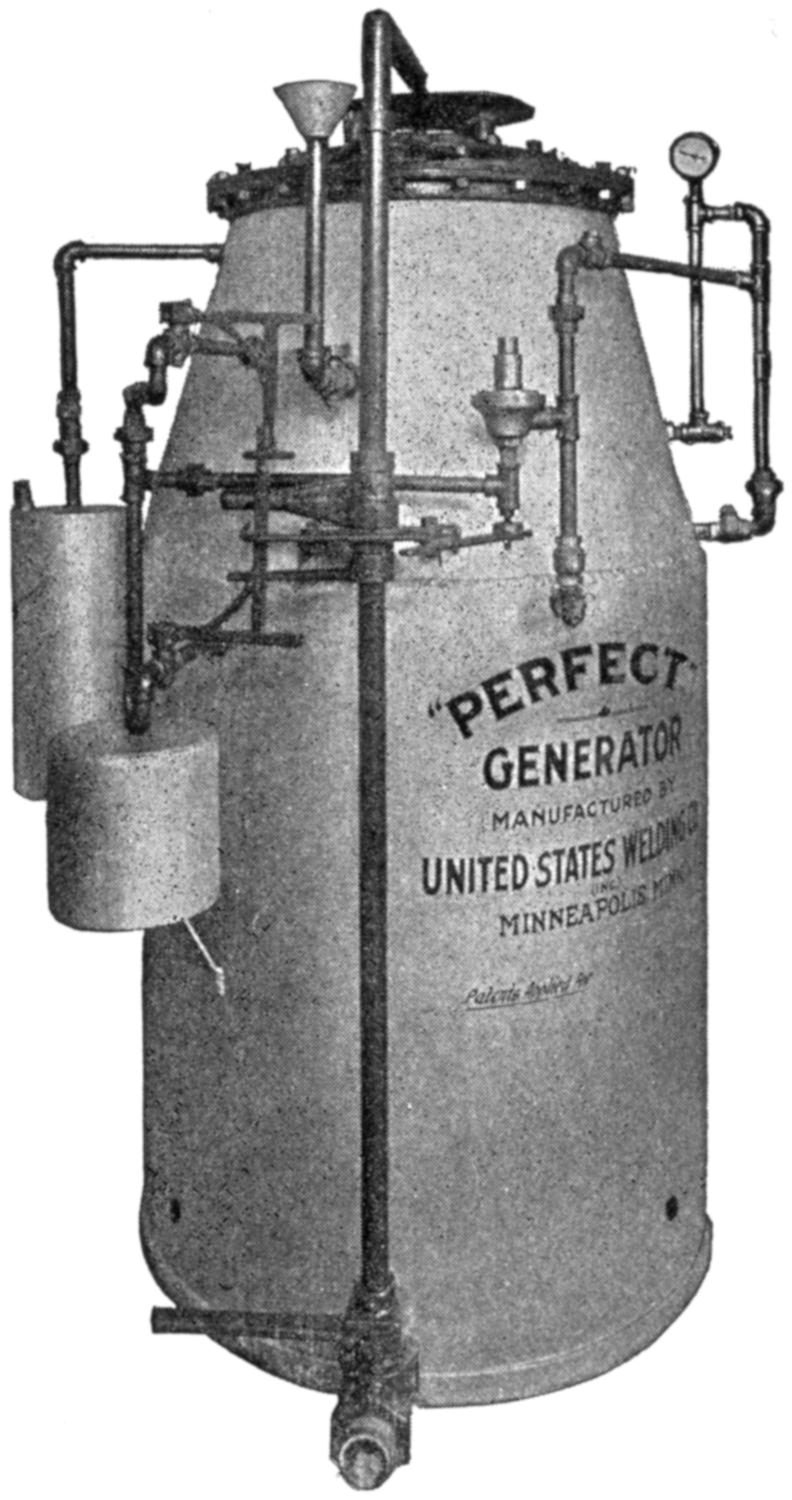
Fig. 20.—A Generator for Producing Acetylene under Pressure.
(31) In setting up apparatus for the first time, the regulator containing the 3000-pound gauge is attached to the taller of the cylinders, which holds the oxygen gas, and the other regulator is fastened to the shorter cylinder. The hoses, which should be cleared of all powder or scale on their interior, are then added. The black hose should connect the oxygen regulator to the torch valve, marked “OX” and the red hose, the acetylene regulator to the torch valve stamped “AC.” In attaching regulators to full cylinders the “cross-bar” on the regulator should always be turned out, that is to the left, until it turns freely, to insure all pressure being released from the diaphragm, before the cylinder pressure is turned on. Another precaution that should be observed is the “cracking” of the cylinder valves, before attaching the regulator, in order to blow out any dirt or foreign particles that may be lodged there, otherwise they will be carried into the regulator seat,[32] or lodged in some small passage, which will impair the working of the apparatus. Then too, if no truck or clamping device has been provided, both the oxygen and acetylene cylinders should be securely clamped or wired together, a rule which should be insisted upon at all times, whether in a job shop, manufacturing concern, or training school, or any place where top-heavy oxygen cylinders are being used. No particular harm results if these cylinders are turned over, which is very easily done on account of their rounded base, if no regulator is attached, but very frequently regulators are attached and the hose connecting the same to torch is found in the operator’s way. The slightest pull or tripping on this hose will upset the cylinder, usually demolishing the regulator and expensive gauges and at times causing much confusion among the workmen, on account of the loud hissing noise given off by the escaping gas. Always secure the drums or the cylinders in a safe manner.
(32) In turning on the gas, the oxygen valve is opened wide until seated and the acetylene valve is only partially opened. Often the question is raised as to where the operator should stand, especially when dealing with high-pressure oxygen. It is recommended that the operator should stand at the side and towards the rear when performing this operation, for sometimes an unreliable gauge may be attached, which if bursting, would send the glass into the operator’s face.

Fig. 21.—Acetylene Flame Blowing away from Tip.

Fig. 22.—Addition of Oxygen to Acetylene Flame.

Fig. 23.—More Oxygen Pressure Applied. Flame Contains Slight Excess of Acetylene, and is Known as “Carbonizing.”

Fig. 24.—“Neutral” Flame. Correct Proportions of Oxygen and Acetylene Gases.

Fig. 25.—“Oxidizing” Flame. Too much Oxygen Present.
(33) As soon as an operator has gas pressure in his regulators, he begins wondering how much pressure should be placed on his line, that is, the portion between the regulator and the torch. Of course, this depends upon the size of the tip, but the operator should have some means of approximating this pressure without going to his manufacturer’s chart every time. A neutral flame, that is, theoretically equal parts of oxygen and acetylene, is desired for welding.[33] Now in lighting, the flame should stand away from the tip a slight distance, in torches other than the low-pressure type, while in these there will only be a good full flame issue from the tip. Enough oxygen must be in evidence to bring this acetylene flame down to the neutral point. If not enough pressure is used, this result cannot be obtained, and of course, more pressure must be introduced. It is better to have too much pressure than not enough on the line, for the operator may use his torch valve to again regulate this pressure and is always sure of enough gas. Theoretically, all adjustments should be made at the regulator, but in practice this is very seldom carried out. The accompanying cuts will illustrate the five conditions which every welder should be familiar with, in the flame adjustment. Fig. 21 shows the acetylene turned on full; no oxygen has as yet been introduced. The flame has a yellow appearance and is very rich in carbon, as can be seen by the soot given off. In Fig. 22 we see the oxygen being turned on; the yellow flame (A) is gradually giving way to a white part at (B). In this condition we say that a feather flame exists. Fig. 23 shows slightly more oxygen pressure. In Fig. 24 we have the neutral flame, which can be readily recognized on account of its bluish white color and well-defined outline,[34] appearing like the end of an unused piece of chalk, only, of course, much smaller. In Fig. 25 can be seen an excess or too much pressure of oxygen. It will be noticed that the neutral flame assumes a more bluish color, is a little pointed, and a very noticeable hissing sound is in evidence. This is what is called an oxidizing flame and will be again referred to. Too much oxygen is used. Operators who attempt to turn on the oxygen first and then light it, will find that it does not burn, and their efforts will be useless. In picking up a torch for the first time, any operator can turn on one valve and detect by the odor of the gas, whether it is oxygen or the fuel gas, and can light it in accordance. Some operators, however, attempt to turn on a little of each gas and light. This is not to be recommended, for flashbacks may occur. When the welder accustoms himself to turning on enough pressure to accommodate whatever sized tip he may have, he will find that there is no great need for paying attention to the pressure gauges on his regulators[35] except to check up on the full drums of oxygen, and to tell whether he has enough gas left to complete a certain piece of work.
(34) A neutral flame is theoretically composed of equal parts of oxygen and acetylene ignited, but this ratio is very seldom worked out in practice. There is usually an excess of oxygen in evidence. A neutral flame is generally spoken of as being over 6000 degrees Fahrenheit, and this does not vary with the different sized tips as most welders think. Of course there are different quantities of heat between a very small tip and a large sized one, but the temperature of the flame is the same.
(35) If too much acetylene gas is used, a feather flame such as was seen in Fig. 23 will appear. This has a carbonizing effect on the weld, for it introduces carbon and causes the weld to become very brittle.
(36) If too much oxygen gas is used, the effect shown in Fig. 25 will take place, and the weld will have oxygen introduced, which is a very detrimental feature, and is particularly noticeable in working on steel, for it raises a white foam over the surface of the melted metal, which sometimes is worked right into the weld itself. An experienced welder will always know just what kind of a flame action he is obtaining on his weld, not because he takes the flame away every time he wishes to look at it, but he can tell by the action of his metal exactly the nature of his flame.
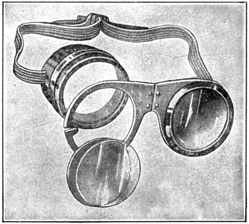
(37) Infra-red (heat) and ultra-violet (light) rays present to a small extent in the neutral flame are injurious to the naked eye. Colored glasses or goggles are used to shield the eyes when working with this flame. Too dark a glass should not be used, as it will cause a strain upon the eyes more injurious than the flame. Exposed metal frames should be avoided too, as they hold the heat and burn the operator.
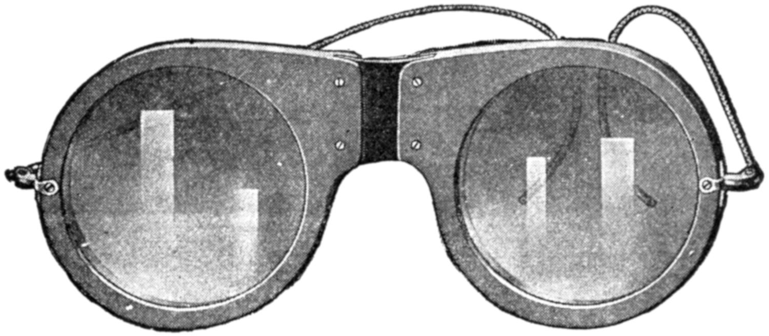
(Courtesy of the Chicago Eye Shield Co.)
Fig. 26.—A Spectacle Made for Welders, having a Frame of Fiber and Arranged so that Lenses may be Replaced.
(Courtesy of the Chicago Eye Shield Co.)
Fig. 27.—Showing Cover Glass which Protects the Colored Lens and the Replaceable Features of a Modern Goggle.
(38) To shut off the apparatus for several hours or so,[36] it is best to relieve all pressure from the lines, such as hose and so forth, and to do this close both tank valves; open the torch valves; release the tension on the regulator, by screwing the “cross-bar” to the left, and finally, close the torch[37] valves. It is quite necessary that these torch valves closed, for quite frequently, if a small tip is in the torch and an excess of oxygen pressure comes through the line, when both torch valves are open, much of the oxygen may back up the acetylene line and cause a serious flashback when lighting up. This can be avoided by keeping both torch valves closed when not in use.
(39) If a valve on an empty acetylene cylinder is left open the acetylene gas will escape, and mixing with the air, which is a supporter of combustion, a very inflammable mixture will be formed. If any fire is present, such as might be smouldering in a forge, possibly not used for several hours or so, or a match lighted, or a flame started in any way, an explosion is likely to occur. When an acetylene cylinder is exhausted, as far as possible, in a moderately high atmospheric temperature, then shut off for a while and the temperature drops, air will be drawn into the vacuum thus formed when the valve is again opened. In this manner an explosive mixture forms in an empty acetylene cylinder and is certainly to be avoided. Care should be taken, especially in winter, to guard against such occurrences, as in some outlying shops a decided change in temperature takes place between closing time and starting up time the following morning. Acetylene tanks should always be securely closed when empty, not only for the above reasons but insomuch that each contains acetone, which is likely to escape if the tank is thrown around. Acetone is very costly and used extensively in the manufacture of smokeless powder, so that at times it is hard to replenish.
(40) Oxygen has an affinity for oils and greases, and should not be allowed to come in contact with them, especially in confined places, as a spontaneous combustion may result. Oils and greases should never be used around oxy-acetylene welding apparatus and on nearly every apparatus on the[38] market the words “Use no oil,” will be found. Despite this precaution, however, many times ignorant operators will be found squirting oil into the holes around the regulator cap, and through the gauges, in order, as they say, to allow them to work easier. This use of oil should be discouraged, and the sooner the better.
[39]
(41) In equipping a shop for welding, in addition to the welding apparatus, the operators are many times undecided whether it is advisable to have a planed metal or a brick top table to use for welding purposes; each has its advantages, but were there a choice of one or the other, it is suggested that the brick-top table be used. The theory of having a planed metal top for lining up work does not prove as satisfactory in actual practice as might be expected, for the simple reason that the average welder generally places his metal in direct contact with this cold top, and much of the heat which is supposed to go into the weld is conducted away by the table top, producing a hard, brittle weld. In the case of cast iron, these welds are generally porous. Then too, the operator to a large extent depends upon the table top for lining up his work and does not study his contraction and expansion as thoroughly as he might. The result is that many of his pieces warp in cooling. To rectify the first objection it is advisable to cover the table top with asbestos paper as shown in Fig. 28. In the second place, sometimes clamps are used to hold the work in position. Preheating without a layer of bricks on a metal-topped table is not to be recommended.
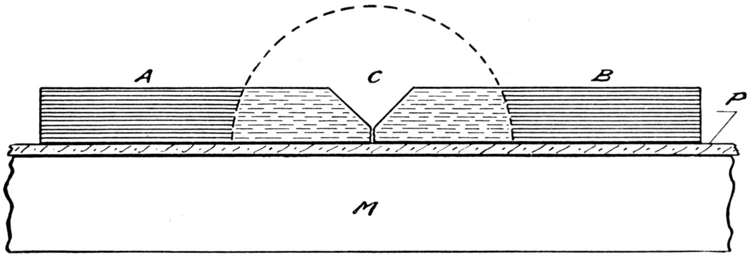
Fig. 28.—Method of Holding Heat when Welding on Metal Top Tables.
Asbestos paper, P, is laid upon the metal top, M, and the pieces, A and B, placed upon P in such a manner that the weld can be made at C. The asbestos paper prevents too much heat escaping from the bottom of the weld.
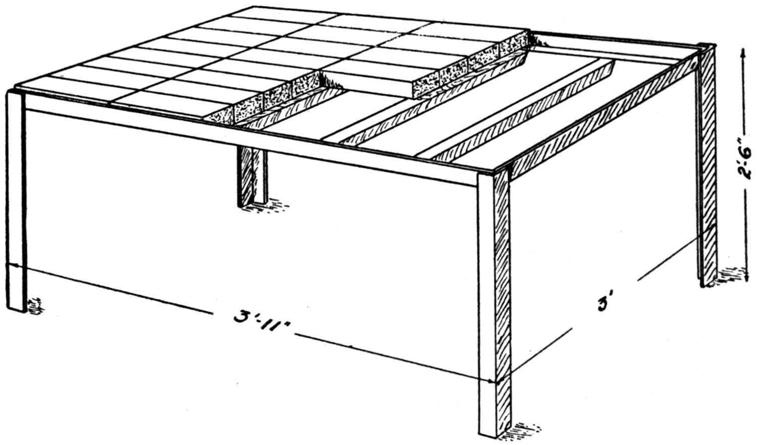
Fig. 29.—A Fire-brick Table for Welding.
Angle iron measuring 2 by 2 by ¹⁄₄ inches is welded together in the manner shown and covered with fire-bricks which measure 2¹⁄₂ by 4¹⁄₄ by 9 inches.
(42) A fire-brick table, made up along the lines shown in Fig. 29, is very easily constructed and can be used for all sorts of jobs. It is well to have everything clear around the legs and have no braces to cut the operator on the shins[40] or to interfere in any way with his work. The best fire bricks obtainable should be used. A large number of extra bricks should always be on hand for they come in very handy in most of the welding operations, and in fact to conduct a welding shop without fire bricks could almost be likened to a blacksmith’s shop without an anvil. Besides being used for table tops, preheating furnaces of a[41] temporary nature may be built and the bricks used to jack up and align many jobs which could not be handled otherwise.
(43) An emery wheel plays a very important part in a commercial welding shop, insomuch that rust, scale, and unnecessary metal can be removed in a very short time by its use. A flexible shaft attachment should be on hand, if possible, or a portable grinder of some kind, for in many cases where the casting, or the piece being worked upon is too heavy to bring to the emery wheel, the wheel can be brought to it and many places ground down by its use that would be impossible with a stationary grinder.
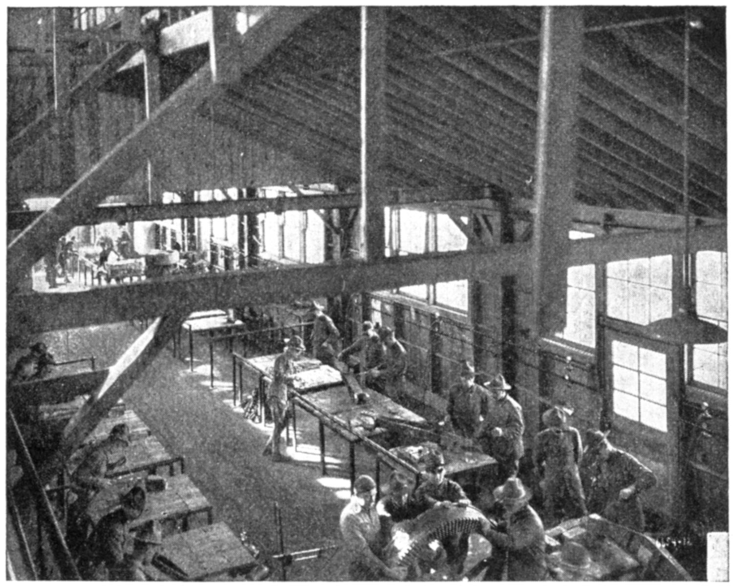
Fig. 30.—One Shop in which Instruction in Steel is being Given, at the Ordnance Welding School.
Note the construction of the welding tables. Two or more may be placed together, to give as large a surface as desired.
(44) Many times when working near a hole which may be threaded, the welder has much difficulty in keeping his[42] metal from entering the hole. At other times it is necessary to back up preheated work such as aluminum, to prevent its collapsing. Ordinary clay or putty cannot be used for this purpose. The simple reason being that when metal is heated it expands and the clay or putty in giving off its moisture contracts, showing two opposite reactions. Retort cement is a name given furnace cement mixed with shredded asbestos, this, as well as carbon flour, has been found to be very satisfactory for filling in holes and backing up pre-heated work. Retort cement is purchased in airtight containers, hardening very quickly when brought in contact with the air, so at all times it should be kept in containers similar to those in which it is purchased. It cannot be reclaimed once it is hardened.
(45) A blacksmith forge will be the medium of saving much valuable gas and time in a welding shop. It will heat up parts to be welded in very short order and while in this condition they may be welded and then thrown back into the forge and allowed to cool very slowly.
(46) Several pails of water should always be located where welding is being done to prevent fire from flying sparks; to cool the torch tips and filler-rods, when working on large jobs; to keep certain parts of work being welded cool, and to harden or temper other parts.
(47) A simple and efficient manner of handling flux in the welding shop has puzzled many welders, on account of the flux containers being easily upset, their inaccessibility and the action of the air upon large quantities of flux. A simple method of overcoming this is to cut in two, a two and one-half or three-inch pipe coupling and mount it by welding on a square piece of one-eighth inch plate, as shown in Fig. 31. This type of container is very hard to upset; may be used when working on preheated jobs; is easy to get at on account of its shallow nature, and, as it only holds a[43] small amount of flux, it can be cleaned out frequently and a fresh flux will always be available.
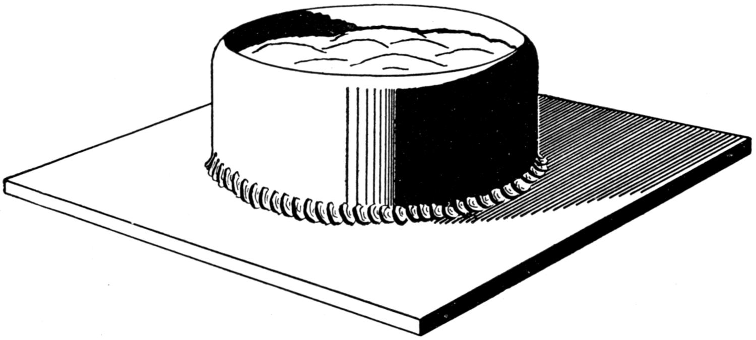
Fig. 31.—A Good Flux Container for the Welding Table.
(48) Additional equipment beneficial to the welder will be a quantity of various sized carbon rods and blocks; asbestos paper; goggles; V-blocks for lining up shafts and an assortment of mechanics’ tools, such as wrenches, hammers, chisels, hack-saws, and other things which might be used in dissembling or assembling various kinds of machinery.
(49) Another important item which is generally overlooked in the average welding shop is the question of ventilation. Although the welding flame itself contains no objectionable gases, those from fresh charcoal preheating fires, those given off when some of the alloys of the filler-rods are melted when brass, copper, and other metals are being worked on, and from gas engine exhausts are not desirable. At times they will give the operators violent headaches unless means are taken to carry them off. The ventilation should be such that it will not directly affect the work. Drafts are to be avoided as much as possible, for many times they will warp pieces being preheated if allowed to come in direct contact with them. It is a good thing to remember that indirect ventilation and plenty of it is a prime requisite in a good welding shop.
[44]
(50) Occasionally in setting up a welding apparatus, a leak may be noticed along the lines, some time after the plant is in operation. Leaks on either the oxygen or acetylene lines are to be considered dangerous as well as costly and therefore to be avoided at all times. When the cylinder valves are closed on the drums containing the gases, and the hands on the low-pressure gauges of each regulator are seen to drop or reduce their pressure when the torch valves are shut off and allowed to remain so, this is an indication that there is a leak between the regulator and the torch. It is not desirable to use a match or a flame of any kind in testing for leaks. There are various methods employed by the cautious welder, but about the best of these is a soapy solution of water, which is kept in a can at all times and is applied with a paint brush. If this solution is applied to any leaky part, bubbles will form immediately and the leak will be located.
(51) At times, when working in isolated places, where repairs cannot be had, and no means have previously presented themselves for testing out the cylinders or the apparatus as a whole, it may be found that the threads or ground seat on the cylinder valve of the regulator which is connected will be in such a condition that a leak is in evidence. Or it may be that the threads will not permit the seat being drawn up sufficiently to make it airtight. In cases of this kind, the welder must find some means of proceeding[45] with his work, and while it will be impossible for him to use white lead or any oily substance with safety, he may stop the leak with litharge or lead oxide mixed with a small quantity of glycerine. A string soaked in this solution may be wound around the main connection and the swivel nut screwed up to the seat as far as it will go. If allowed to harden for a short time, the litharge will set and a very satisfactory temporary repair will be effected.

Fig. 32.—Method of Attaching Hose to Connection so it cannot Pull or Blow off.
(52) The method shown in Fig. 32 of attaching connections to hoses so that they will not blow off when pressure is applied is a very simple and effective means of overcoming this difficulty. Undoubtedly it will assist some operators in solving the trouble that has been occasioned by the ordinary hose clamps, especially when doing cutting or heavy welding work where the gas pressure is considerably higher than usual. The wire used should be large enough to prevent cutting the fabric in the hose.
(53) An injured hose which may leak should never be used after the leak is noticed unless some means are taken to repair it. The use of tape in trying to repair hose on an oxy-acetylene welding outfit should never be permitted. The most efficient way of overcoming an injury of this kind is to cut the hose at this part and insert a piece of pipe. The ends of the hose are then wired to this pipe and a union is thereby effected which will generally outlast the life of the hose. Special connections for this purpose are put out by most welding companies, so that a supply may be on hand if hose trouble is expected.
[46]
(54) When transporting welding apparatus, occasionally the “cross-bar” on the regulator is lost and many times the operators do not know what is to be done. The purpose of the “cross-bar,” as we have already seen, is only to apply pressure on the diaphragm springs, so that if a set screw of the same diameter and same thread as those of the “cross-bar” can be found and screwed into its place with a wrench, a section of filler-rod can be welded across the top of it and the use of the regulator will not be impaired. If a special thread is used by any particular company, a piece of brass or iron can be turned down in a lathe to fit.
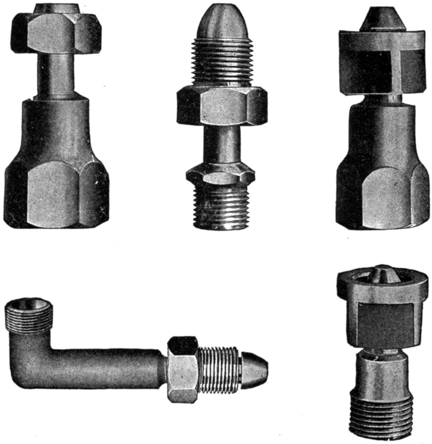
(Courtesy of the Bastian-Blessing Co.)
Fig. 33.—Various Types of Adaptors Used to Connect Regulators to Cylinders having Different Connection.
(55) The manufacturers of practically all regulators use the quarter-inch tapered pipe thread in attaching the cylinder connections to the regulator and do not depend upon the threads being gas-tight, so they solder them in. There are various types of cylinder connections put out by different manufacturers of the gases and occasionally it may be necessary to use a cylinder of gas which contains a different connection than is supplied on the regulator. Various adapters, such as shown in Fig. 33, are supplied to overcome this difficulty, but at times the operator is confronted with the very embarrassing situation, of having a cylinder of gas and his regulator of different connections, but no adapter suitable. This predicament is usually found when some very important work is to be done and sometimes far from a supply depot. At times the operator may have an adapter which will fit the cylinder but not the regulator. If this is the case, his difficulty can be very easily overcome, for generally all adapters are made of two parts, “sweated” together, and have the same quarter-inch tapered thread as used in the cylinder connections on the regulator. The adapter can be separated, the tank connection removed and the correct connection “sweated” into the regulator.
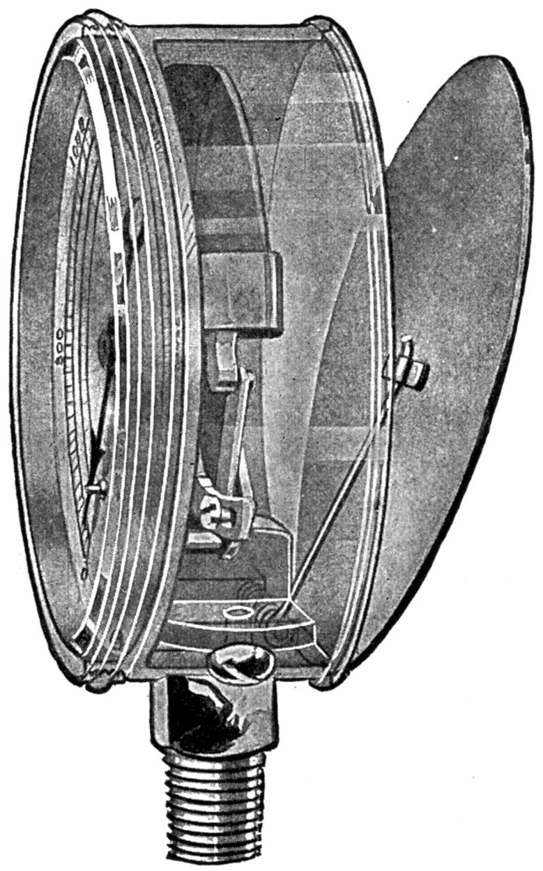
(Courtesy of the U.S. Gauge Co.)
Fig. 34.—Showing Solid-front and Hinged-back Features of a “Safety-first” High-pressure Oxygen Gauge.
(56) Most gauges used in the oxy-acetylene industry to[47] indicate gas pressure are of the Bourbon type. The most recent types of the oxygen high-pressure gauges are constructed with a hinged back and a solid front, which means that should an oil or foreign matter enter the gauge from any source whatsoever and tend to burst it, the back would be blown off and there would be no glass that could possibly fly around. This is a safety device which has been welcomed with much enthusiasm on the part of the oxy-acetylene industry.[48] When leaks occur in gauges, it is always best to remove the gauge from the regulator, stopping the hole temporarily with a pipe plug and return the gauge to the manufacturers for repair. These gauges are very delicately constructed and can be rendered useless if handled by the inexperienced. A great many times after the case of the gauge has been jarred or loosened, the screws connecting this case to the inside working mechanism are tightened up, breaking the soldered connection holding the spring tube on the inside of the gauge. This causes a leak which can[49] be repaired quite easily if the operator is able to solder it. It must be remembered, however, that if the flame is brought in contact with any of the springs that their tension will be lost and that the gauge may not operate correctly after this repair is made unless great care is exercised.
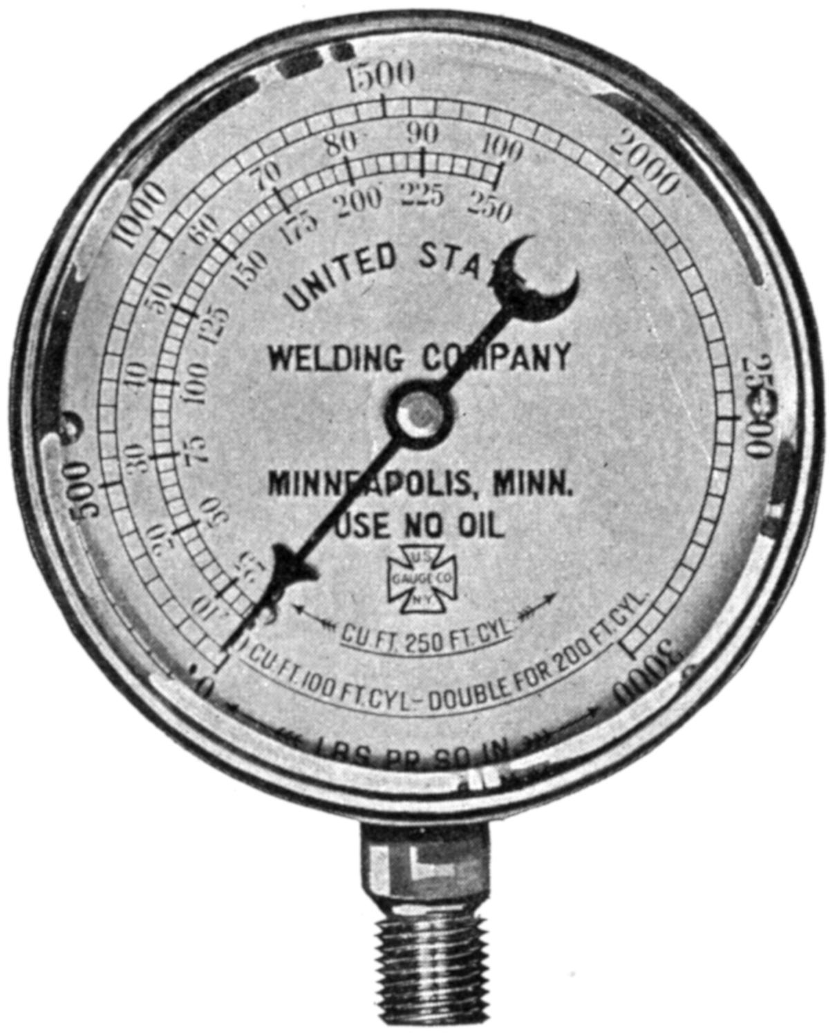
Fig. 35.—A 3000-pound High-pressure Oxygen Gauge.
(57) Undoubtedly there are many welders who in beginning to operate their welding apparatus conclude that their gauges must be at fault when they show a reading after apparently all pressure has been released in closing down the apparatus. It is to avoid the impression that the gauge is at fault that time is here taken to show that even though the cylinder valve is closed and the “cross-bar” on the regulator screwed out that when the torch valves are opened to drain the lines there will still be a reading on the high-pressure[50] gauge if the regulator seat is in good working order. It is simply a case of gas being trapped between the regulator and the cylinder valve. To reduce this reading it is only necessary to screw in the “cross-bar,” thus opening the regulator seat. This could be avoided if the cylinder valve were closed first and the torch valves opened while the regulator “cross-bar” were still screwed in, then as soon as the gas had left the line, the torch valves could be closed and the “cross-bar” on the regulator could be screwed out until free.
[51]
(Courtesy of the Messer Mfg. Co.)
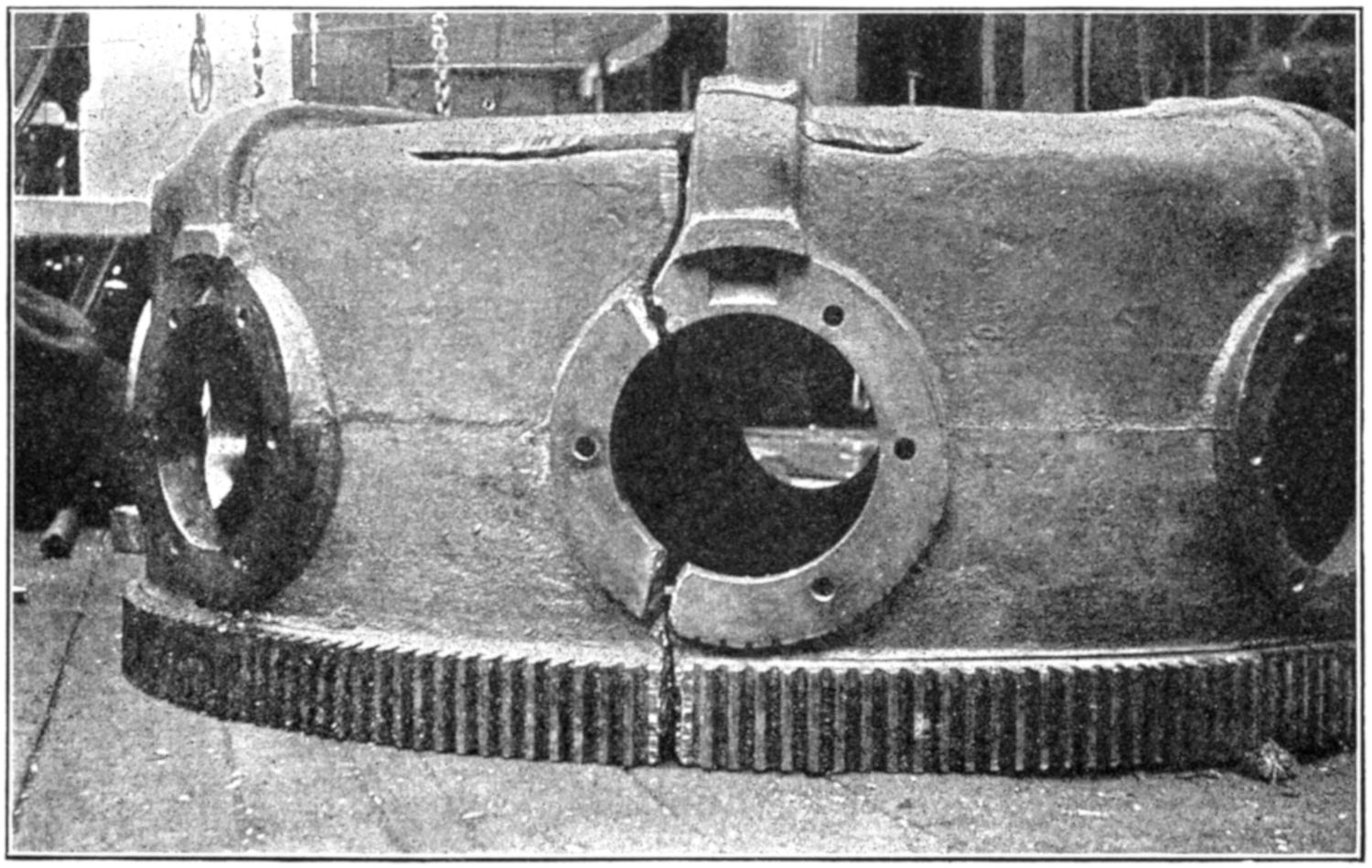
Fig. 36.—A Large Job Prepared for Welding.
(58) Preheating, as applied to oxy-acetylene welding, means the application of heat to the article to be welded in some manner which is usually different than by the welding flame itself. Charcoal, coke, kerosene, crude oil, coal and natural gas are used for this purpose. The principal reasons for pre-heating parts to be welded are: To take care of the effects of contraction and expansion on the confined ends; to save time, gas, and material; and to make[52] a better weld by making it quicker and with less chance of burning up the metal.
(Courtesy of the Messer Mfg. Co.)
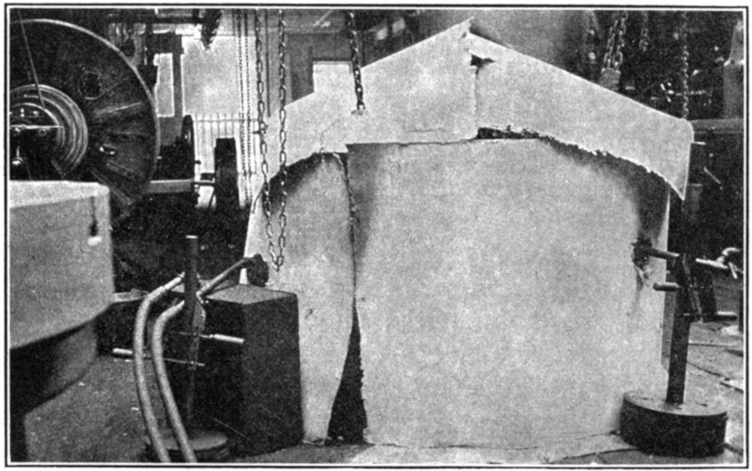
Fig. 37.—Showing how Large Work can be Covered with Asbestos Paper when Preheating.
(59) On account of the ductile qualities of steel, there is not quite as much heat used in preheating, to take care of the contraction and expansion, as in cast iron. On brass work a very dull red heat is considered sufficient, or otherwise the alloys might burn out. When preheating aluminum, there will be no change in color as the heat is introduced, so other methods are used to determine the correct temperature. Three methods are used for this purpose by most welders. “Half-and-half” soldering wire will usually melt when applied to the surface of aluminum which is preheated to the proper state; the puddle stick when drawn smartly across the heated surface should scrape off the oxide and leave a clear blue streak if the work is in condition[53] to be welded; and if a medium-sized tip is brought down so that the neutral flame just touches the surface for a second or two, the metal will sweat, if at the proper temperature, and small globules which have the appearance of mercury will stand out on the surface.
(60) The beginner must study contraction and expansion in order that he may know when and where to apply it in figuring out his work. Many welding jobs have turned out to be failures through lack of knowledge in this respect. Take, for example, a water-cooled cylinder block of the ordinary gas engine; the water jacket may be broken when the water is allowed to freeze in it. This problem has certainly confined ends, but some welders have attempted to weld such jobs cold, that is, without preheating, and possibly have succeeded in executing what they thought was a very fine weld, but upon examination, have discovered that the cylinder walls, which are very accurately machined, have been warped to such an extent that the block is rendered useless. This is strictly a “preheating” job, and the cylinder should be brought to a dull red heat if the best results are to follow.
As has been stated elsewhere in this volume, the weld should not be considered successful unless the piece worked upon can be returned to a usable state.
(61) Several different fuels have been mentioned, all of which can be used for preheating purposes. Charcoal is considered the best agent for general welding, as it gives off a very steady heat which will gradually be absorbed by the article worked upon, bringing it to the heat desired and holding it there throughout the welding operation. It will then permit very gradual cooling, as this sort of fire takes a long time in dying—a desirable asset in work of this kind. On account of the scarcity of charcoal and its high price, other agencies are used and chief among them are torches using kerosene, crude oil, or city gas, as a fuel. These usually[54] heat up the work more quickly, but care in their manipulation is necessary. A preheating torch to be used in conjunction with city gas can be very easily constructed, if the details of Fig. 38 are observed. This proves to be a very efficient and cheaply constructed apparatus.

Fig. 38.—Preheating Torch, Constructed of Black Iron Pipe, for Burning City Gas.
(62) When work is being preheated, it is best to have it protected from all drafts, to prevent warping. Possibly the most extensively used material for building up temporary ovens to hold the heat and protect the work from the air currents is fire brick and with it asbestos paper. When setting up an ordinary casting for preheating, these bricks are built up in builder’s fashion, about four inches away from the piece itself, as shown in Fig. 39, and practically level with the top of the piece. If charcoal is to be used, draft spaces are left in the first row of bricks as shown, and the charcoal ignited through the openings with the welding torch. The work to be welded should have the line of weld at the top if possible and be set up from the floor, or the surface[55] upon which the oven is resting, on one or two fire bricks, in order that the full benefit of the heat will be received. Asbestos paper is then laid across the top, and the oven will appear as in Fig. 40. When starting the fire, a layer of charcoal, a matter of two or three inches thick, is at first used, but as the chill is taken off the piece the oven can be filled to the top, and usually this is enough to complete the work.

Fig. 39.—Temporary Preheating Oven, Built of Fire Brick.
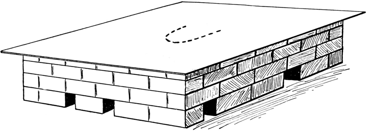
Fig. 40.—Temporary Preheating Oven of Fire Bricks Covered with Asbestos Paper.
(63) In order to protect the operator, when working over hot fires, it is recommended that the asbestos covering be left on, and that only a small section immediately in the vicinity of the weld be removed, which can be accomplished by cutting a “U” in the paper as shown by the dotted lines in Fig. 40. This can be turned back, exposing the place which is to be welded, and at the same time protecting the operator, to a large extent, from the unnecessary heat. When the weld is finished, this lap can be turned back and the piece allowed to cool. On pieces which require turning and must be welded in several different positions, the preheating oven, as it is called, should be built considerably larger, to provide for handling the work. It must be remembered that during the entire operation, the piece should be left inside the oven and should not be removed to a welding[56] table. Some beginners make the mistake of doing this. When welding with the charcoal in closed rooms, during the winter months, the fumes will be found to be very disagreeable and means should be taken to provide indirect ventilation, otherwise the welders will be troubled with headaches and smarting eyes.
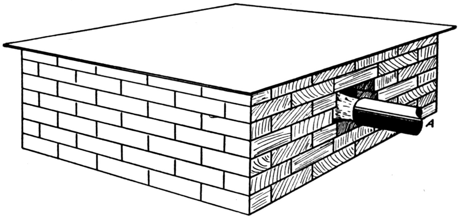
Fig. 41.—Showing How Oven is Built when Preheating Torch is to be Used. Torch is Shown at (A).
(64) When using preheating torches, the ovens are built much closer to the work and do not have the openings along the bottom row of bricks. They are made as tight as possible, and in some cases it will be found advisable to build up the walls with two layers of bricks, with asbestos paper between them, in order to hold the heat and cause the work to heat up in a more uniform manner. A hole is left in one end of the oven, through which the flame of the preheating torch is introduced as shown in Fig. 41. It is not thought best to have the torch flame come in direct contact with the work which is being preheated, and a baffling plate of metal or brick is placed directly in front of the flame, in order to spread it around the oven. Judgment will have to be used in all such work.
(65) The setting up of the work, when preheating, is an important point overlooked by many welders, especially so in the case of aluminum. Care should be taken to see that the[57] work has a good solid setting and is braced at a sufficient number of points, to prevent its sagging when in a preheated condition. Many times when working on rough surfaces, a few firebricks distributed around the bottom of the oven with a dab of putty, clay, or retort cement, placed upon them, will form an excellent cushion upon which the work can rest and the operator may feel confident that no sagging will occur.
[58]
(66) In order to know how to weld, it is quite imperative that the operator first know the kind of metal he is to work on. It is surprising to find how few welders know their metals thoroughly. An incident might be cited where some welders depend upon the sparks given off by the emery wheel in determining the kind of metal they are about to weld. They will approach the wheel; grind off their work, noting the sparks; return to their welding table; choose their filler rods and do their welding without any delay whatsoever, much to the consternation of their fellow workers. There are four simple ways in common use to distinguish between cast iron, malleable iron, and steel; they are: By the cross-section of a fresh break, by application of the welding torch, by the sparks given off when applied to the emery wheel and by the chisel test.
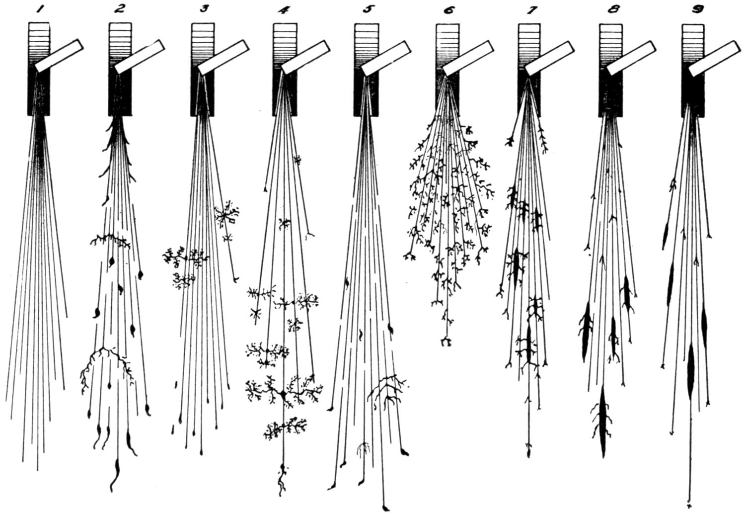
Fig. 42.—Characteristic Sparks of Different Irons and Steels Thrown off by an Emery Wheel. Wheel should be Clean Cutting and Run about 7000 Feet per Minute.
(1) Shows cast iron. No sparks unless impurities are present.
(2) Is wrought iron almost free from carbon. Heated particles thrown from wheel follow straight line. These become broader and more luminous some distance from their source of heat.
(3) Illustrates mild steel action. Small amount of carbon present causes a division or forking of the luminous streak.
(4) Shows the effect of increasing the carbon from 0.50 to 0.85 per cent in mild steel. The iron spark lines diminish: the forking of the luminous streak occurs more frequently, being subdivided by re-explosions from smaller particles.
(5) Is a piece of carbon tool steel. The iron lines are practically eliminated with the increase of the explosions and subdivisions, causing display of figures.
(6) Gives the spark of high-speed steel, containing in addition to 65 per cent carbon, other alloying elements, chiefly tungsten and chromium.
(7) Represents a manganese spark. (Occasionally found in cast iron.)
(8) Shows spark thrown from old grade of “Mushett” steel.
(9) Represents a magnet steel spark.
(67) Externally cast iron usually has some sand on its surface and its cross-section shows the grain to be fine, even, and to have a dull grayish color. The surface of malleable iron contains no sand and its grain is very fine, such as cast iron, but slightly darker in color. A very fine steel veneer is on all surfaces of malleable iron, which is much lighter in color. When the welding torch is applied to cast iron, no sparks are given off, but when applied to malleable iron a bright spark is thrown off which breaks in falling, showing that the outside material is steel. These sparks soon cease and the metal which is molten is covered by a heavy oxide[59] or skin which recedes or draws away from the flame slightly, showing a very porous cast-iron interior. When brought in contact with the emery wheel steel sparks, which are very luminous and break in falling, are given off first in the case of malleable iron, but they soon change to the dull red spark[60] of cast iron. When a chisel is applied to cast iron, the iron chips off; when applied to malleable iron the edge will curl up, then chip off when the cast iron is reached. The cross-section of cast steel shows a bright, coarse, silvery gray grain. When the torch is applied a distinctively steel spark which is luminous and breaks in falling is thrown off. When applied to the emery wheel steel sparks are thrown off; when the edge is chipped by a chisel it will curl up.
METHODS OF DISTINGUISHING METALS
| Here are five methods, any one or all of which may be used to learn the nature of common castings which might confuse the welder. | ||||
| No. | Test. | Malleable Iron. | Cast Steel. | Cast Iron. |
|---|---|---|---|---|
| 1 | Outside Appearance. | Generally smooth and free from all sand, weighs about same as cast iron. | Rough surface with sand in evidence, weighs much more than cast iron. | Surface fairly smooth but generally shows some sand. |
| 2 | Cross-section Test. | Ring of bright steel crystals outside, with darker iron crystals inside. | Large, bright, luminous, silver crystals. | Fine, uniform, dark gray, crystals. |
| 3 | Emery Wheel Test. | Few steel sparks and then iron sparks from interior. | Bright, luminous sparks that break in falling. | Dull red sparks that do not break. |
| 4 | Chisel Test. | Surface will curl and interior break off. | Will curl before breaking. | Will chip off. |
| 5 | Torch Test. | Gives way before flame and delivers few sparks. Metal becomes porous. | Gives forth bright sparks that break in falling. | Gives no sparks except where there are impurities. |
Fig. 43.
[61]
(68) The metal in the filler-rod should be the same in practically all cases as the metal to be welded. There are few exceptions to this rule, but the principal one is that of malleable iron. The cast iron in the rods is of a very good grade and generally much better than the piece to be worked upon. To permit the ready flow of the rod and eliminate oxidation, as much as possible, three per cent of silica is generally used in the casting of filler-rods for cast iron welding. Piston rings and other scrap iron should not be used for filler-rods, as they contain many impurities such as core-sand, dirt, grease, etc., which will ruin the weld. It is disheartening to see some operators attempt to economize on the filler-rod. It is not an uncommon sight to see several dollars’ worth of gas and the same amount of the welder’s time, together with a few cents’ worth of filler rods all lost, and the operator’s reputation ruined. This, because an attempt is made to save the few cents involved in the filler-rods by substituting a rod of a very poor grade.
(69) A flux is not used, as many suppose, to cement the filler-rod to the metal. It is used purely as a cleansing agent and may be likened to the acid used in soldering. It does not act on the metal until the latter has reached the melting-point, but then it starts to break up the oxides and clean the surface. This action permits the metal to flow together more readily. A cast-iron flux is always used in welding cast iron, to break up the oxide, because the cast iron itself will melt before the oxide and no matter how hot the metal is it will not flow together as long as this oxide is present.
(70) To obtain the best results, reliable fluxes should always be used. Occasionally an accident will happen to the flux can, when the operator is on some isolated job and a substitute flux must be obtained at once. Equal parts of bicarbonate of soda (cooking soda), and carbonate of soda[62] (ordinary washing soda), may be purchased from any grocery in the powdered form and mixed together thoroughly. This will tide the welder over until he can return to the shop and replenish his supply.

Fig. 44.—Whenever Possible, the Beginner should “V” His Work, and Complete His Weld from One Side only. On heavy work, however, it will be necessary to “V” out from both sides, as is here shown.
(71) The flux is generally applied by means of the filler-rod. One end is heated and dipped in the flux; enough will adhere to break up part of the oxides, on the ordinary-sized job. The flux is carried to the work, which should be at the melting-point and introduced between the flame and the metal. Oxides will break up immediately and the metal will flow together, but it must be remembered that the flux has no action on cold or moderately heated metals. The flux as has been explained is used to clean the metal and break up the oxides. To the oft-repeated question, how often should the flux be applied, answer is made as follows: As often as it is necessary to clean up the metal and break up the oxides. All fluxes should be kept in airtight containers when not in use, to keep their chemical contents in the very best condition and it is best to use only a small quantity of flux on the welding table at one time.
(72) Oxy-acetylene welding is purely a fusing process and the most important points to remember in executing a weld are, to eliminate the entire crack in the fracture and[63] to add the filler-rod without changing the character of the metal. On thin pieces of metal it is possible to depend upon the force of the flame to entirely penetrate to the depth of the crack but on work three-eighths of an inch thick or over, it is well to “V” out or remove some of the surface metal around the crack in order to get down to the bottom. By “V-ing” we mean to chip or grind off each edge at an angle of approximately 45 degrees, so that the opening will form an angle of 90 degrees where the two pieces come together, with the crack at the bottom portion of the “V.” This should NOT be ground down to a knife edge, for it will readily burn up. It is preferable to leave about one-eighth inch along the line in order that the pieces will fit together and the proper alignment may be obtained. If two pieces of cast iron have been prepared in this manner the neutral flame of the welding torch is brought down in such a manner that the tip of the cone just licks the metal. The heat is not applied directly to the line of weld to start with, but rather to the surrounding part. This is done in order to get the entire locality in a condition which will not withdraw too much of the heat from the line of the weld, once the fusing is begun. If it is found that the tip will not produce enough heat to bring the metal to a red heat in a fairly short time, a larger tip should be used.
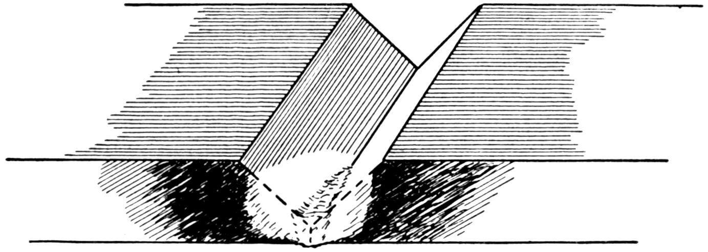
Fig. 45.—Starting a Cast-iron Weld.
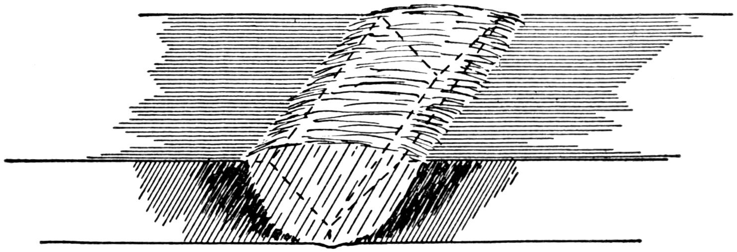
Fig. 46.—Reinforcing a Cast-iron Weld.
(73) No set rule can be given as to the sized tip to be used on various kinds of metal. It will largely depend upon the welder’s ability and judgment. When the metal is brought[64] to red-heat, the neutral flame or cone is brought into contact with the lowest portion of the “V” and held there until it is seen that the metal is melted on both sides. The filler-rod, which has previously been heated at one end and dipped into the flux so that an amount adheres to the end of the rod, then carries this flux to that portion of the weld which is under way. Enough flux is blown off the rod into the weld to clean up the surface and permit the metal flowing together. The crack should be melted together all along before any additional metal is added, for the elimination of the crack is extremely important. It might be noted that as soon as the metal begins to flow freely the neutral flame should be raised a short distance from the work in order to better control the molten metal. In order to build up the metal to the original state along the line of weld or perhaps reinforce it, the sides and bottom of this “V-ed” out part are then brought to a molten state and held there while the filler-rod which brings up more flux is stirred into this metal and the end melted off. In this way the flame does not come in direct contact with the filler-rod and is used only to keep the metal in a molten condition. As much of the filler-rod can be melted off as is thought necessary to bring the weld to the normal condition of the metal or an additional reinforcement can be built up, if it is thought advisable. If care is taken in the above procedure, many of the blow holes and hard spots in the weld will be eliminated, for any impurities that might gather will be[65] displaced by the melted metal and will float to the top. In cooling a weld of this kind, care should be taken not to permit any sudden chilling for this will tend to harden the weld. It is best to cool it slowly by burying it in slack lime, ashes, or wrap it with asbestos paper to keep the air from it as much as possible.

Fig. 47.—This Problem does not Require Preheating to Care for Contraction, as the Ends of A and B are not Confined.
(74) There may be a great many causes for blow holes and hard spots in the weld, but probably they can all be traced directly to the lack of heat. It must be remembered that welding is a fusing process and heat is absolutely essential. Therefore it should not be used sparingly. The application of heat always causes expansion. There are no exceptions to this rule, likewise upon cooling the metal there will be a contraction. Outside of the actual welding, that is, the fusing of the metal into a homogeneous mass, perhaps the greatest problem that the welder has to confront is the expansion and contraction of his metals. Whenever the ends of two pieces of metal which are to be welded are free to move, or even one end, there will be no difficulty encountered with contraction and expansion, but if these ends are confined, it is an entirely different problem.
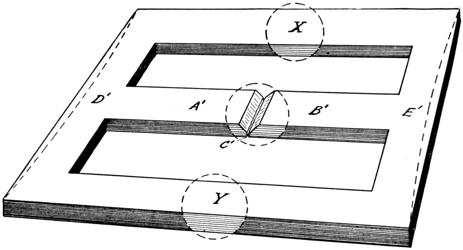
Fig. 48.—Preheating Problem. Ends of Bars A′ and B′ are Confined.
(75) To illustrate this point more clearly, the following very simple example will be given. In Fig. 47 we have two bars of metal A and B which have been beveled off or “V-ed”[66] out as shown at the point C. Now as soon as the heat is introduced at C there is bound to be an expansion of the metal at that point. Naturally if the pieces were heated slowly and for a considerable distance, the cool ends of these bars would be forced outward. We will assume that the heat is introduced very rapidly and the metal is brought to a molten state; that instead of the contraction forcing the cool ends outward, whatever expansion there is, is taken care of, at the weld, for the metal when melted will readily push together. It is also assumed that the bars are heavy enough to overcome what slight force might be in evidence from the expansion. A weld is then made and allowed to cool. As it cools, there is bound to be a contraction along the line of the weld and the welded piece will be slightly shorter than the work before the weld, for it will draw in the pieces A and B. As can be seen, there is no particular force preventing the contraction of such a weld for the ends are free to move. However, let us turn to Fig. 48, which constitutes an entirely different problem. It might seem that the ends A′ and B′[67] appear the same as A and B in Fig. 47, but such is not the case. The ends farthest from the weld are confined, held in place by a heavy frame which does not permit their free movement. When heat is introduced at the point of welding C′, about the same action takes place as in the previous problem, but as soon as the weld commences to cool let us see what happens. The bar A′B′ must be shortened so there is an inward pull on the bars D′ and E′. If this work were cast iron or aluminum it would certainly be broken by the strains set to working and would naturally break at C′, where the metal is still hot. If it were steel or one of the ductile metals, it might twist and warp in its endeavor to overcome these internal strains. This illustrates in a very simple manner the difference between what is known as a “cold” and a “preheating” job. In the first no provision is made for expansion and contraction. In the second means are taken to overcome these important factors. In order to provide for the successful welding of the second problem, it is only necessary to heat up the bars X and Y about the same distance as the center will be heated, and keep them in that condition while executing the weld at C′, then allowing the whole to cool gradually.
(76) Before commencing to weld, or even turning on the gas, it is well to see that all preparations have been made and all materials on hand to bring the weld or whatever job it may be, to a finished state.
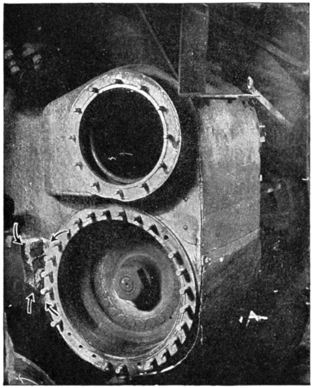
(Courtesy of Ben K. Smith, U. S. Welding Co.)
Fig. 49.—This Locomotive Cylinder was Welded at the Saddle, near the Frame.
(77) As a specific example of a simple welding operation let us consider that two cast-iron bars, measuring one by six inches and twenty-four inches long are to be welded end to end. To start with it would be necessary to “V” off the ends that were to be joined at an angle of about 45 degrees,[68] leaving about one-eighth inch along the bottom edge to line the metals up with and to see whether they are in proper position. If the bar were to measure exactly forty-eight inches when finished it would be necessary to move these bars apart about one-sixteenth of an inch in order to provide for their contraction. It is assumed that the weight of the bars would be sufficient to prevent their pushing apart when the line of the weld is brought to a molten state and that[69] the expansion will be taken care of within the weld. The bars after being lined up are ready for welding, but there are such things as filler-rods, flux and goggles that are necessary to have on hand before starting to work. It is well to have a few fire bricks, a little asbestos paper and a bucket of water convenient, in case these things are needed. The acetylene gas should then be turned on and ignited. A sufficient pressure should be passing through the regulator, when using a medium, or high-pressure apparatus, to cause the flame to leave the torch tip about twice the distance of the diameter of the orifice of that particular tip. Then turn on the oxygen until a neutral flame is obtained. On some torches it is necessary to make a second adjustment by turning on a little more acetylene gas and still more oxygen, until a goodly sized neutral flame results. Apply the flame to the pieces, so that the neutral flame will just lick the surface of the metal. Move the torch slowly forward and backward on each side of the “V” until the two edges are a dull red color, or better still a bright cherry red, then hold the torch stationary until the metal in the “V” nearest to the operator commences to melt. Then bring the filler-rod end in contact with the flame to get it heated and plunge it into the flux which should be near at hand. Enough flux will adhere to break up the oxides and by placing the rod between the flame and the metal, enough flux will be introduced to allow fusing of the metal. Proceed in this manner until the metal in the bottom of the “V” is properly fused throughout its length. Do not add the filler-rod, up to this point unless necessary. In holding the flame, see that the preheating flame will heat the parts yet to be welded. The weld should be made away from the operator. After the metals along the bottom have united and a good foundation has been obtained, then start the weld at the beginning once more, working the flame across the piece, in the same manner as[70] before; bringing the metal to the molten state and stirring the filler-rod in it. As the filler-rod melts, the amount of molten metal naturally increases and the flame is moved along the weld as fast as the metal is added. It is important that the metal is in a molten condition. It is almost impossible to get too much heat on this type of work. Build up the weld slightly higher than the original piece. It may be found in finishing up the corners that the velocity of the gases or the force of the flame will be sufficient to blow the melted metal away. This may be overcome by directing the flame at a different angle, and will cause no difficulty after a little practice. Trouble, too, may be experienced on thin cast-iron sections by having the metal collapse through the force of the flame, but this can be remedied in the same manner. While the weld is still in a heated condition, it is possible to finish it by scraping the surplus metal off with the side of the filler-rod, the chill of which has been taken off before it is allowed to come in contact with the molten metal. Another popular method that will produce even better results is to use a very heavy rasp file to bring the weld down to the measurements desired. During all of the previous operations the flame never leaves the line of weld. When the weld is completed, the torch is shut down by turning off the oxygen first, and then the acetylene, and the welded bar is covered up to prevent its cooling too rapidly.
(78) Problems in expansion and contraction should not be difficult, if it is remembered that heat causes expansion and the withdrawal of heat, or cooling causes contraction. As previously stated, when the ends of the pieces which are being welded are free to move, there is not much danger of having contraction strains set up. Where the ends are confined,[71] measures must be taken to overcome this. In welding large pulley wheels, for example, it may be advisable to do the job without taking time to preheat. Breaks may be in evidence at any part of the wheel and generally the ends are confined, such as in the case of a spoke. If it is borne in mind that the expansion will take care of itself, the contraction is the only consideration, in a case of this kind. The welder will see that if he can spring the edges apart a sufficient amount to provide for the spoke coming back to normal when welded, he will have no difficulty. The way to proceed in a case of this kind would be to open the rim by sawing it and then introduce a jack or some sort of a wedge between the hub and the rim. This will open the crack in the spoke the amount desired. As soon as the weld is executed and while still hot, the jack is removed to permit the rim being drawn in. Later the rim can be welded, by introducing jacks between the spokes and the same procedure followed. It always must be remembered that provision must be made for the contraction, even though it be only one thirty-second or one-sixteenth of an inch. The distance will depend entirely upon the welder, as some operators use small tips and cover a small area, while others employ larger tips and cover twice the area. It is therefore impossible to set any specific distance and each welder should try to figure this out for himself.
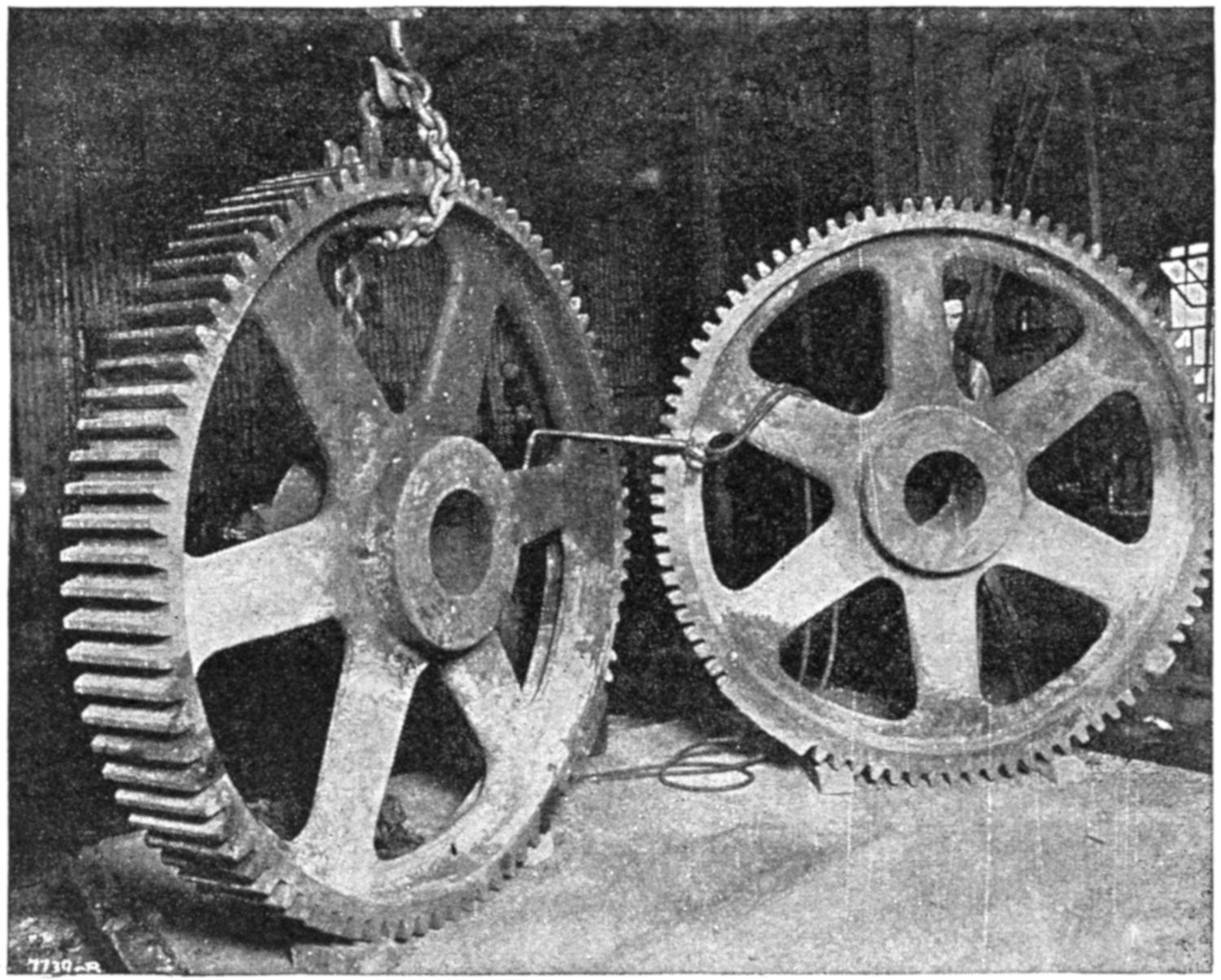
(Courtesy of Torchweld Equipment Co.)
Fig. 50.—Large Cast-iron Gear Wheels. Although the Face on These Gears Measured 10 Inches, New Teeth were Added by Blanking In, as Shown in the Right-hand View, and Later Machined.
(79) There are many jobs not of a preheating nature that at times cause perplexity on the part of the welder. A good example of this is a cast-iron gear wheel. A number of its teeth have been broken out. Now there are three very common ways of building up or repairing such castings. First by aid of carbon blocks, cut to form and the teeth cast in by the use of the torch; second, by blanking in the space between the teeth and then sawing out the individual tooth or cutting it out with a milling machine or shaper; third, by[72] building up each tooth with the welding rod and torch, and later dressing it down with a file. One very important point must be uppermost, when dental work on gears is being done, a good foundation is necessary, for regardless of how well the tooth may be shaped, if it is not firmly secured to the wheel itself, it will be of very little value. Another very important point is in the finishing of such gears, to see that the teeth which have been added correspond in the pitch and mesh exactly as the others do. The importance of seeing that things of this nature are machined correctly should not require mention, but it has often been found that machinists are very careless about finishing this kind of work and if[73] anything goes wrong, the welder is naturally at fault. Therefore it is always well to put the gears which have been welded back into place and turn them over slowly by hand to see that they are in good condition before the power is turned on. In allowing this kind of work to cool after it has been welded, some operators permit it to be hurried, with the result that there may be hard spots to confront the machinist when finishing. If he ruins one or two of his cutters he will naturally frown upon all welding work. It is therefore desirable for this and many other reasons to have the weld come out as[74] soft as possible, and great care should be exercised in cooling. Any weld that is subjected to machining, allow it to cool slowly in slack lime, in ashes, or cover it securely with asbestos paper. Occasionally it may be found difficult to find sections of carbon blocks which will take care of a job of this kind. Many welders who have had to run around the country, and do jobs in isolated places, have found that the carbon centers, from the ordinary dry cell batteries, which may be found practically everywhere in a discarded condition, can be shaped on an emery wheel and patched together in a manner that will permit their use. However, when such are used, it is quite necessary that they be heated a little with a torch beforehand, in order to drive out any chemicals or acids that may be contained in them. Unless these chemicals are removed, the molten metal coming in direct contact with them might be injured to a considerable extent.
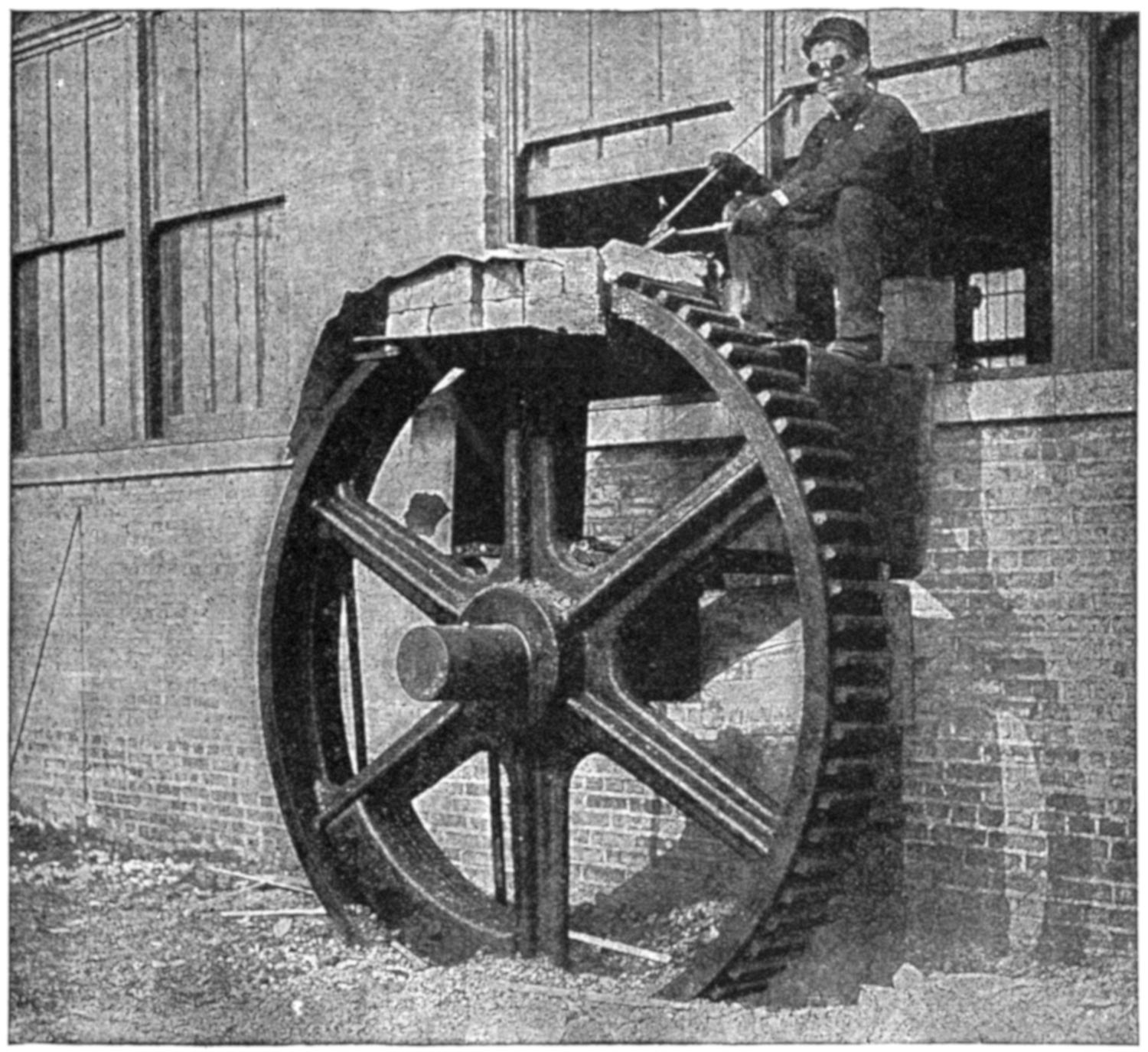
(Courtesy of the Oxweld Acetylene Co.)
Fig. 51.—This View Shows new Teeth being Welded in an 8¹⁄₂-ft. Cast-iron Gear, Weighing over 5 Tons. Note the Improvised Preheating Oven.
(80) Ofttimes there are castings upon which parts wear off in a very short time. There may be very little strain upon these parts, yet the constant wear will weaken them in time. It is well to remember the action of a carbonizing flame when executing work of this kind. Introduce an excess of acetylene when finishing up the work. It will be found that with a strongly carbonizing flame, carbon will be taken up by the molten metal and the finished weld will be considerably harder and will wear longer than if it were executed by a neutral flame. An abrupt cooling will chill the metal on the surface and make it wear longer than it would otherwise.
[75]
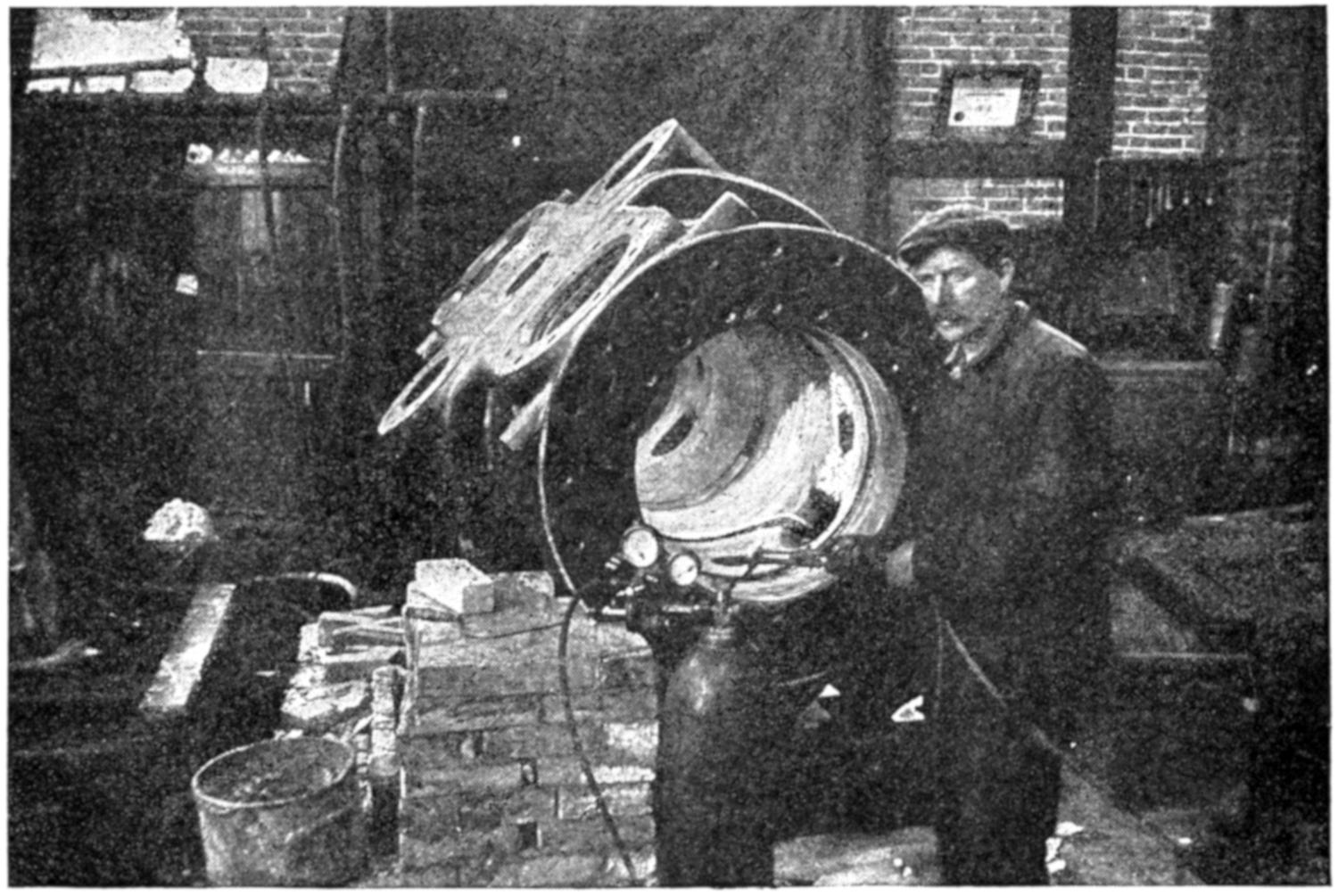
(Courtesy of Ben K. Smith, U. S. Welding Co.)
Fig. 52.—View of Locomotive Cylinder with Three Jackets 3 Inches Thick. This job weighed over 16 Tons and Required Fifty-six Hours of Welding.
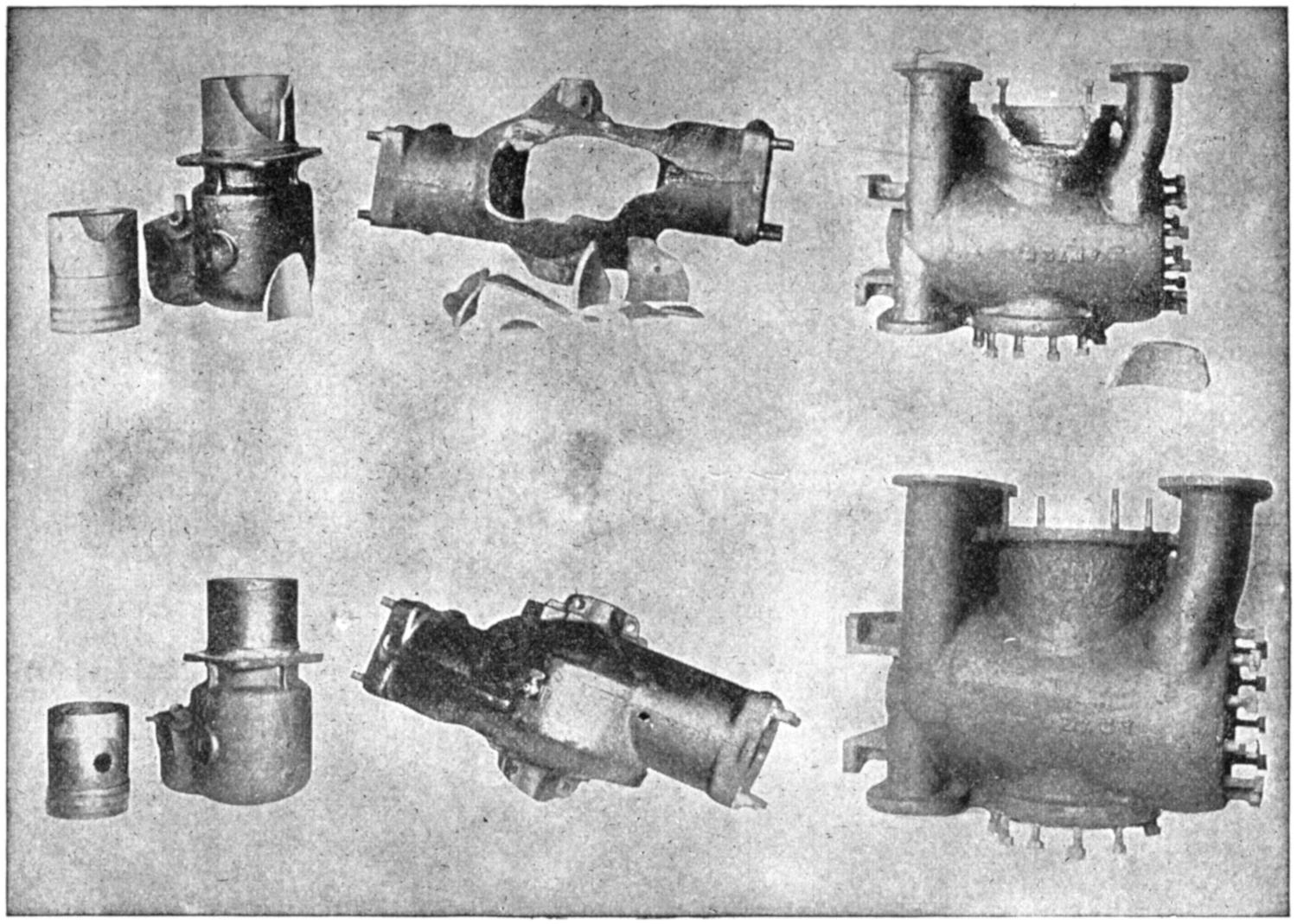
(Courtesy of Torchweld Equipment Co.)
Fig. 53.—Various Types of Cylinders before and after Welding.
(81) The true index as to the success of a weld will depend
entirely upon the finished job. If it is usable, i.e., if it can
be put back into service again and give satisfaction, it may be
considered a successful weld. If a piece were to be warped,
distorted, contain hard spots which could not be machined,
or have internal strains, which would not make it safe for
use (such as fly-wheels), it could not then be considered
satisfactory and it would be only wasted energy. Perhaps
one of the most common jobs in the ordinary commercial
shop, and one which is the most abused, is the common cast-iron
cylinder block found on the gasoline engine. This is
so constructed that there are two walls of metal, very thinly
cast; the innermost being the cylinder wall, and the outermost[76]
a water-jacket. The cylinder wall is machined very
accurately to accommodate pistons moving at a very rapid
rate, up and down and yet holding compression. The
upper part of the cylinder is called the head, and generally
has two or more valve seats which must be in alignment
with the valve guides to make an airtight seat for the valves.
Now this water-jacket is usually very thin, perhaps three-sixteenths
to one-quarter inch in thickness, and when there are
two, three, four, or more cylinders cast in one block, there are
bound to be internal strains set up in casting within the
piece itself. These strains are removed to a large extent
by baking the rough casting before machining. Generally
there are some strains left in every cylinder block of this
nature. If the water in the water-jacket freezes or some
other force comes in contact with the thin castings which constitute
a block, the metal will give way at its weakest point,
and the welder is usually called upon to repair it. At times
these cracks are exceedingly small and the temptation is to
braze or attempt to weld the small portions. However,
as soon as there is heat introduced into the water-jacket and
not into the cylinder wall, there are certain to be strains set
up which, if sufficient, will distort the cylinder and make it
useless unless it is rebored. The sooner welders realize that
work of this nature must be preheated throughout, to a
point as near melting as they can approach without causing
the metal to scale, before any welding is attempted, the
better success will be obtained in these lines. It is quite
necessary to line up the work well, so that it will not sag
when heated. It is best to heat very slowly and cool in the
same manner to insure the best results. There are many
preheating agencies, such as oil-ovens, preheating torches
and the like, but about the best and most reliable agent
known is charcoal, which heats up very gradually, makes
a good even fire and dies down slowly which is the manner[77-
78]
desired. Occasionally cracks will be found in the combustion
head of the cylinder. It is very difficult to get the
torch down inside the cylinder to execute this weld unless
the operator has a special torch for this purpose. Even then
it is difficult to keep the torch lighted when working over a
newly made charcoal fire. For this reason, other means
must be used when working on a job of this kind. First
the crack is accurately located, then a piece is cut out of the
water-jacket just over the crack by means of a chisel, hack-saw
or drill press. Never attempt to remove a piece of this
nature with the flame, for the introduction of heat may distort
the piece at this time. “V” out the crack in the combustion
head and scrape off as much of the brown oxide and
dirt formation as possible. It is well to clean off more than
needed and to even “V” out the crack a greater distance than
is thought necessary. This will insure a good weld being
made in one operation. The cylinder is then preheated with
the crack uppermost so that welding can be executed with the
least possible difficulty. While preheating is taking place
it is well to tack the small section of the water-jacket which
has been removed, to the end of the filler-rod, and place it
too, in the preheating oven, with the end of the filler-rod
projecting so that it will be available whenever needed.
When the cylinder is red hot the weld should be executed;
particular attention being given to see that each part of the
metal is actually fused to prevent any leaks occurring later.
As a rule the welder can tell when he has made a successful
weld by observing the flow of his metal, and it will not be
necessary for him to test out this cylinder weld before adding
the water-jacket. The piece of the water-jacket is then
replaced; it can be very easily handled by means of the
filler-rod which has been tacked on. Weld this section securely
in place and cover the piece of work with asbestos paper and
permit it to cool with the dying fire. When cold, all port[79]
holes in the water-jacket should be closed and the cylinder
tested for leaks. This can be done by introducing water
into the water-jacket and applying
about fifteen pounds of air pressure.
Wet spots will appear if there are
any leaks. If the cylinder is found
tight it should be polished, then
oiled, and the outside given a coat
of filler or painted to make it presentable.
Work is generally very
much discolored when coming out
of the fire. A simple device for
polishing the cylinder bore may be
made by turning out a hardwood
block about three inches long and
a little less in diameter than the
size of the piston. This should be
split as shown in Fig. 54, and[80]
wrapped with very fine emery cloth, then put into the cylinder
and a wedge placed between the two halves. Spread
them apart so they will come in contact with the cylinder
wall on all sides. A screwdriver may be used for this purpose
if necessary. By screwing this into the cylinder its full
depth, with the aid of a little oil, a very highly polished
surface may be obtained.
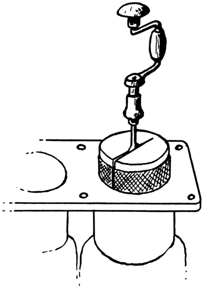
Fig. 54.—Suggested Method of Polishing Cylinder Walls of Cast-iron Cylinder Block after it has been Preheated.
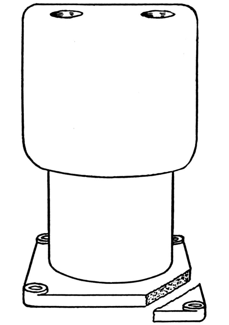
Fig. 55.—Cast-iron Cylinder Block with Part Broken Off.
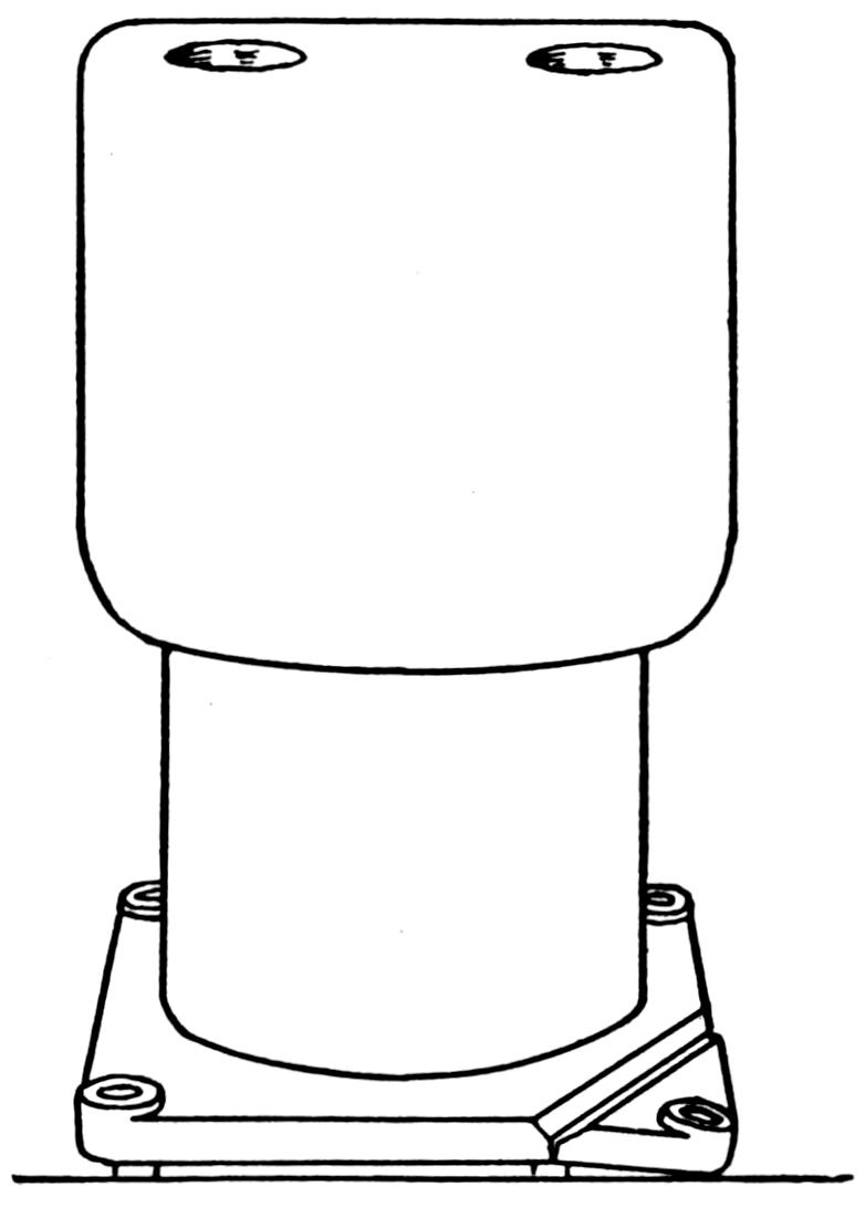
Fig. 56.—Showing how Broken Part on Cast-iron Block should be Lined up before Welding. Position Greatly Exaggerated.
(82) Another cylinder block job that generally causes more confusion than is necessary is brought about when welding on small lugs, such as shown in Fig. 55. When welding these lugs on from the outside only, they generally warp upwards in cooling and it is either necessary to build up the bottom side of this lug or to machine off the entire face in order to have the end square. This can easily be overcome by permitting the lug to sag before welding and then dress off the small portion that continues to sag, after it is welded, rather than face off the whole surface. See Fig. 56.
[81]
(83) The term “steel,” as used in the following pages, unless otherwise specified, will be the term applied to wrought-iron and low-carbon steels. High-carbon and alloyed steels are to be considered only in advanced work and will therefore not be deemed a topic of interest to the beginner in laying his foundation.
(84) The welding of steel is much more difficult than cast iron on account of the many points which must be observed. In cast iron the metal is brought to a molten state and may be worked in that condition for some time without any apparent change in the characteristics of the metal. A flux is used to break up the oxide or scale and the metal will flow very easily. The flux is necessary because the oxide has a higher melting-point than the iron itself. When working on steel, it will be observed that just the reverse is true, that its oxide has a lower melting-point than the steel and consequently no flux or cleaning powder is necessary when working upon it.
(85) A large quantity of steel kept in a molten condition by the flame acting upon it is very easily influenced. The same area is not kept in a molten condition as with cast iron. The heat does not hold to the vicinity of the weld nearly so much as in cast iron because of the greater conductivity of the metal. If the flame is removed, the molten metal will set almost immediately. This means that the flame must be in contact with the metal at all times. It must be a strictly neutral flame or else one of the two gases will be introduced[82] into the weld and its strength will be materially affected. The size of this flame must be such that too great an area will not be covered, yet enough must be covered to keep the metal along the line of the weld in a molten condition. If a carbonizing flame is used, one which has an excess of acetylene, such as was shown in Fig. 23, much carbon will be taken up by the metal, producing a brittle weld. If the flame is oxidizing, that is, contains an excess of oxygen which is noticed by the shortening of the flame and an accompanying hissing sound, Fig. 25, the metal will burn and a white foam will appear on the weld like a milky white glue. This tends to weaken the weld. This same effect will be in evidence if too large a tip is used. On the other hand if the tip is too small not enough heat is obtained and the oxides and other impurities which may be present will not be allowed to float to the surface but will be trapped in the weld.
(86) The filler-rod used on steel should be as near the same grade, if not better than the metal to be welded and should be very low in its carbon content. A pure grade of soft iron wire or mild steel will make a very good filler-rod for ordinary purposes. The size of this filler-rod is very important, for it should fuse at the same time as the metal being worked upon, and unless it does this the weld will not be satisfactory. If the filler-rod is too large it will not be at the fusion point when the work is, and will not fuse with it. If the rod is brought to a melting-point the work will have too much heat and will burn. On the other hand, if the filler-rod is too small, it will burn up before the work is at the fusion point, or in other words, the work will still be too cold when the rod is melted.
(87) There are many different methods of executing a steel weld, and it has been noted that very few experienced welders handle their steel in the same manner. Most of these methods are very difficult to learn and can be perfected only[83] after years of practice. However, a simple method which will produce results is thought the most advisable for the beginner. A careful examination and study of this point has brought out the following method, which is very easily picked up and which dispenses with most of the torch movements that are generally advocated by the old time welders.
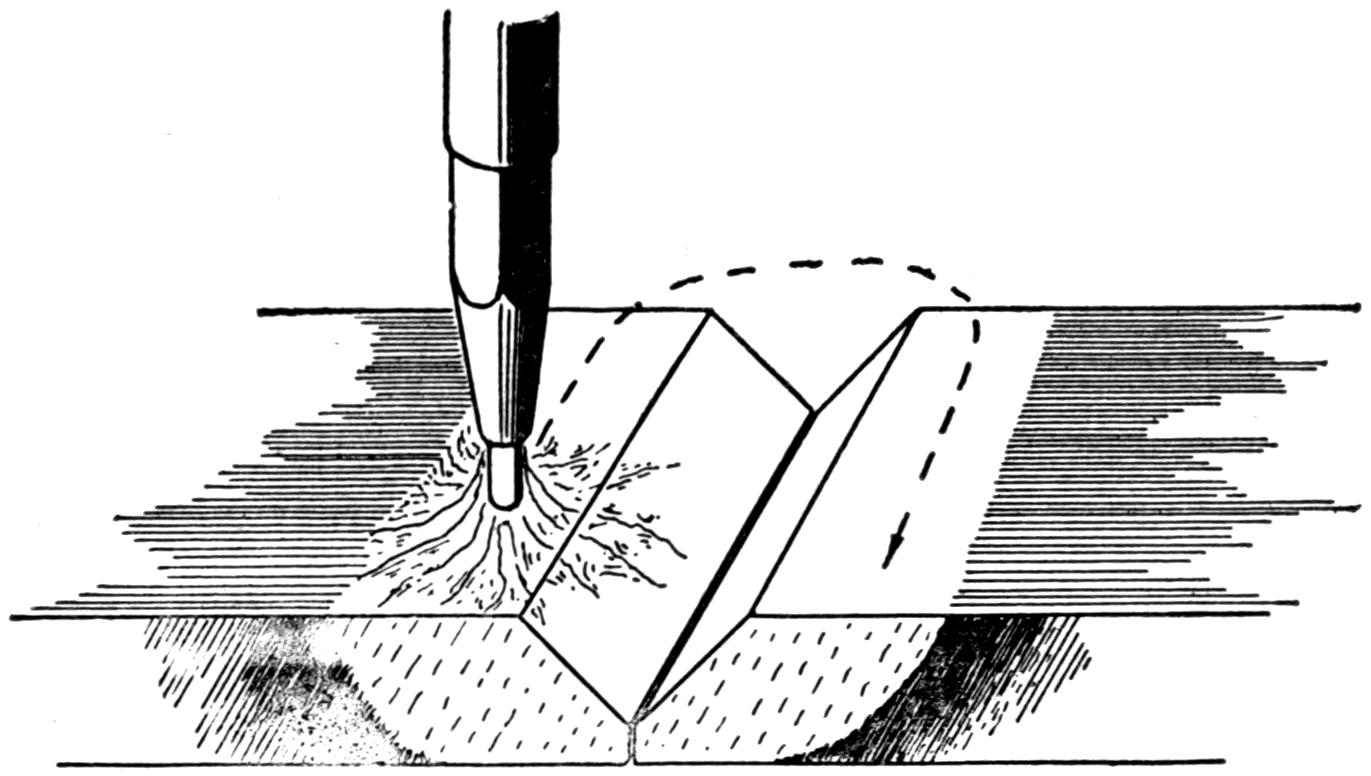
Fig. 57.—Preparing and Heating Steel before Welding.
(88) When welding two pieces of steel bars, the cross-section of which will measure one-half inch by three inches, they are beveled off and prepared in the manner illustrated in Fig. 57, either by means of a chisel, file, or by the use of a grinding wheel. About an eighth of an inch of the original stock is left on the bottom side and the angle formed from these two places when brought together, should be 90 degrees. When the pieces have been prepared and placed in the position shown in the illustration, the neutral flame is then brought down at right angles to the plane of the metal, so that the end of the cone will just lick the surface. It is moved up and down upon each side of the part to be welded until each piece is brought to a red heat, for a distance of at least one inch back. The position of the torch during this operation can be seen in Fig. 57. From this time on, the operator should work as rapidly as possible, for the quicker the fusion[84] of the metal is brought about, the less oxide or scale will appear and a better weld will result. The description of this process may take some length but the actual fusion not nearly so long.
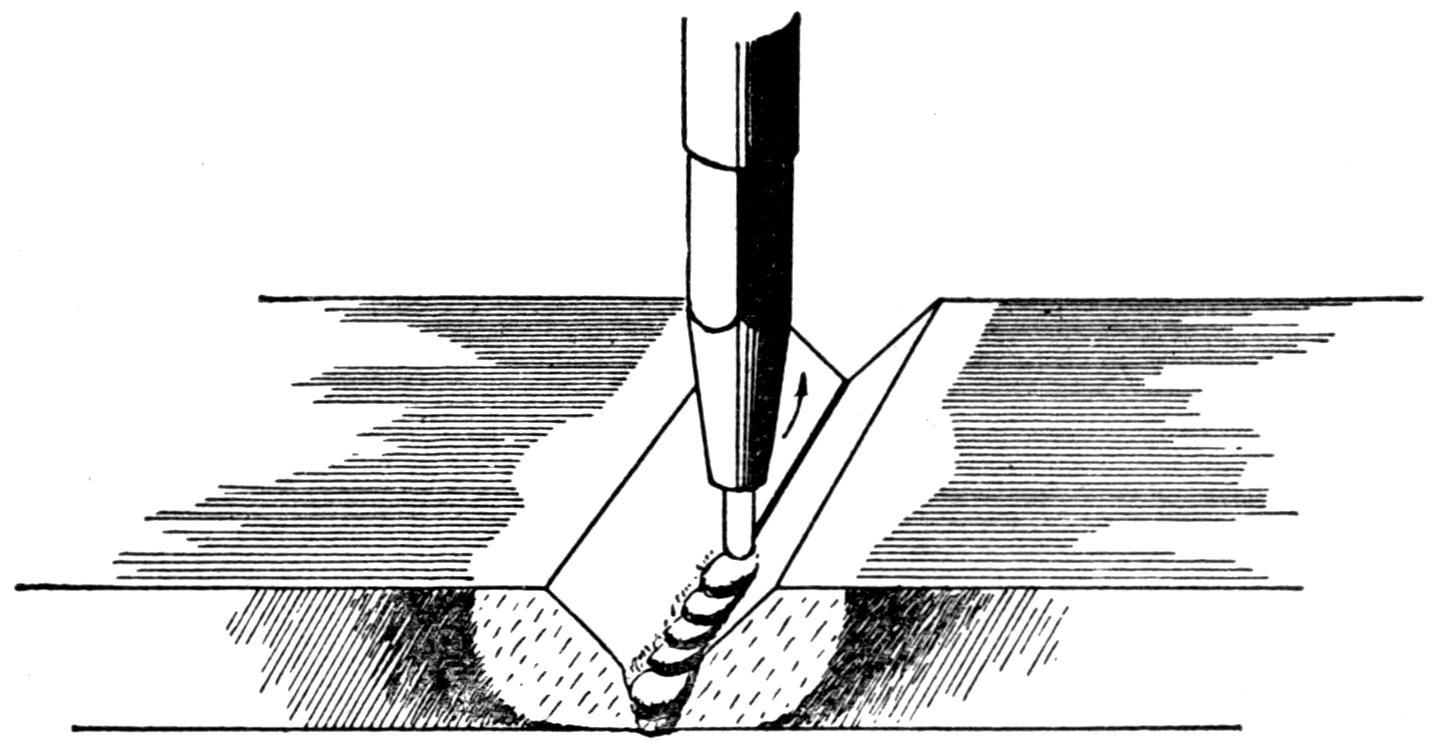
Fig. 58.—In Welding Steel, the Beginner Should Fuse His Pieces together along the Bottom with the Torch Flame, Adding no New Metal. The Metal on Both Sides of the Torch Flame is Melted together until a Small Pool of Molten Metal Appears, then the Torch is Twisted Smartly away, as Shown by the Arrow, and the Metal Allowed to “Set” for an Instant before Proceeding along the Line of Weld.
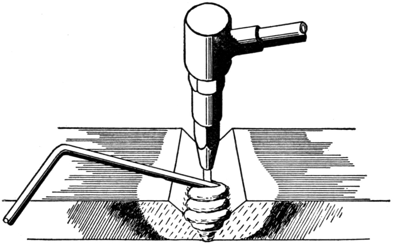
Fig. 59.—Method of Adding “Filler-rod” in Welding Steel. Note that the Rod is Worked behind the Flame.
(89) When the red-hot stage is reached, the neutral flame is brought down to the very lowest part of the “V” at the side nearest the operator and held there until the metal has melted and is about to collapse. The flame is then quickly twisted away for just a second to let the metal set. Perhaps this operation will fuse about one-half inch or less along the bottom of the “V.” This same operation is repeated along the line of weld until the whole piece is fused along the bottom. It will be noted that no filler-rod has as yet been used. After the last portion has been fused, the flame is brought back to the starting-point and played not only on the bottom, which has already been fused, but on the sides of the “V” as well, bringing an area of about one inch in diameter to a molten condition. The tip of the welding torch is held in a vertical position all this time to introduce as much heat into[85] the weld as possible. During this operation the filler-rod, which should measure three-sixteenths or one-quarter inch in diameter, is picked up by the operator’s free hand and its end brought near the heat of the flame so that it may be warmed and will not chill the metal when introduced into the weld. When the melted metal is running freely, the tip of the welding torch is slowly inclined in the direction of the part to be welded and is advanced along the “V-ed” out portion at this angle as rapidly as the metal can be made to melt. This position is shown in Fig. 59. It will be noted that as the flame advances along the line of the weld the molten metal will mount up behind it of its own accord, providing the metal is in a molten condition, when the flame passes over it. During this period the filler-rod is stirred into the molten metal in a circular movement which should be in back of the torch as much as possible. This means that the torch comes in contact with the filler-rod but very little and the rod is melted, not by the flame, but by the molten metal of the piece being welded. It will be noticed at times, when too much metal has been welded and the torch is not advancing rapidly enough, that some of the molten metal will run ahead[86] of the flame, into that part of the “V” yet to be fused, and to the unwary student this will be looked upon as a safe place to add his filler-rod. However, when the piece is broken and the cross-section of the weld examined, it will be found that in this part of the weld, the metal has only been laid on and not fused. The beginner should watch this operation and see to it that this molten metal is not permitted to run ahead of his torch, an act which he can overcome by the proper manipulation of his filler-rod, which really governs all the melted metal behind the flame. If not enough metal has been added to fill in the “V” to the proper thickness, this operation can be repeated until enough metal has been added. By practicing this method the student can be taught to execute a very successful weld and reinforce it all in one operation without any chance of burning his filler-rod or lapping his metal. More practice is required to successfully weld steel than most other metals and the beginner should not be discouraged if it takes him some time to conquer this metal. It should be forcibly impressed on the student that the metal must be in a molten condition before the filler-rod is added, or else it will stick and prevent his working readily and in addition will produce a very faulty weld.[87] Fusion is the thing to bear in mind for without it success cannot be expected.
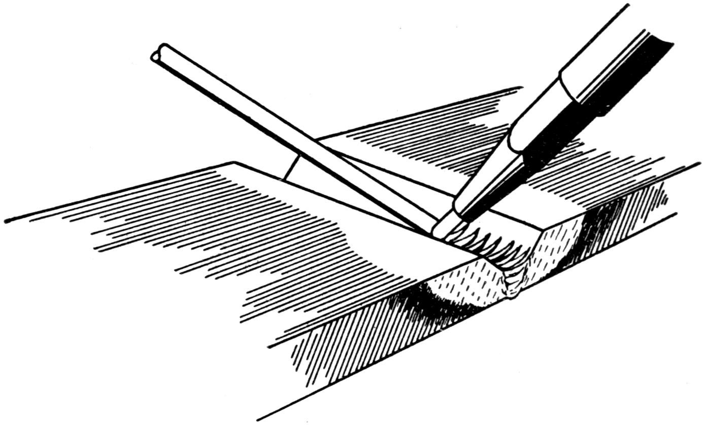
Fig. 60.—This Method of Adding the “Filler-rod” when Welding is not Recommended for the Beginner.
(90) While outside appearances should not be considered as a prime requisite, when beginning it is always well to add more metal than is really necessary in order to reinforce the weld as much as possible. It cannot be expected, however, that a steel with the same cross-section as the original will possess the same properties and be as strong, for a weld is only a casting unless treated otherwise and the steel or wrought iron used in the specimens is of rolled stock. If too much metal has been added and dressing down is necessary, the student will find that by using a slightly oxidizing flame the surplus metal can be burnt away very rapidly and a very good-looking job can be executed much more rapidly than if a neutral flame were used. It is well to remember, however, that this is used only in dressing off pieces and in places where the strength of the weld is not to be jeopardized.
(91) When advancing in steel work, it will be noticed that the same provision for contraction and expansion is not considered in as great proportions as on cast iron, and the reason is quite evident. In cast iron we find the metal is very brittle and will not give without breaking, whereas on steel it is more ductile and will twist and bend before breaking. This does not mean, however, that the important points of expansion and contraction are to be neglected in steel work, for they are very important, as we shall see later on.
(92) It is still supposed that the beginner knows very little about the various kinds of metals, or methods of distinguishing between them. This is of great importance and should at once be overcome, as he will not at all times have someone over him to diagnose his case and tell him the proper procedure.[88] For instance, were he to be given a piece of cast steel to weld, thinking that it was cast iron, he would use a cast-iron filler-rod in executing his weld. The results of such a weld would not be very favorable, and the same would hold true if a steel filler-rod were used on cast iron. An occasional glance at the table in paragraph 67 will acquaint him with the various tests to make when deciding upon the nature of the piece to be worked upon. The tests should be applied in every doubtful instance. When working on cast steel, a student may think that he must have a cast-steel filler-rod, but this is an exception to the general rule and he can use the same style filler-rod as he would employ on ordinary steel work. It might be mentioned here that when working on alloyed and high-carbon steels, the filler-rod generally contains some of the alloy or carbon which will tend to replace that destroyed by the action of the flame in the original metal.
(93) In welding cast steel the same procedure takes place as previously described for steel, and it should present no real difficulties after that process is understood. There may be more sand, oxide and other impurities present on account of the nature of the metal, but these can all be worked out if plenty of heat is applied. At times, when working in steel, it will be found that there may be a small hole develop in the center of the weld and as the torch is worked into this hole it is found that it goes down a short distance and seemingly refuses to be worked out. This is what most welders call a “crater,” and is caused by the metal at the bottom not being hot enough for the surrounding melted metal to fuse it. When found they should be removed before adding any more metal. By playing the torch flame around and around it, so that the heat may be transmitted to the bottom of the “crater” and it brought to the melting-point like the surrounding metal and suddenly jerking the torch away,[89] it will disappear. “Craters” are generally formed during the first part of the weld, especially if the “V” is narrow, and they are hard to handle when deep. Under no circumstances should the filler-rod be melted into them in trying to make them disappear, as this will only mean covering them over.
(94) Some welders find that hard spots develop in their welds which they have difficulty in overcoming, and it is a very serious handicap when the weld is to be machined, for ofttimes it will break very expensive tools and leave a portion of a drill or die broken off in the metal. It is probably safe to say that the principal cause of hard spots in steel welds is due to lack of heat. This, if given careful thought and consideration, will be brought home forcibly to the welder as he proceeds in his work, for the lapping of metals, trapping of oxides, “craters,” too rapid cooling, etc., may all be directly attributed to a lack of sufficient heat. If the metal is in a molten state, all impurities will be brought to the surface, for they are bound to be displaced by the weight of the metal, the same as corks in a barrel will float to the top if water is introduced. The water in this case has a greater specific gravity than the corks.
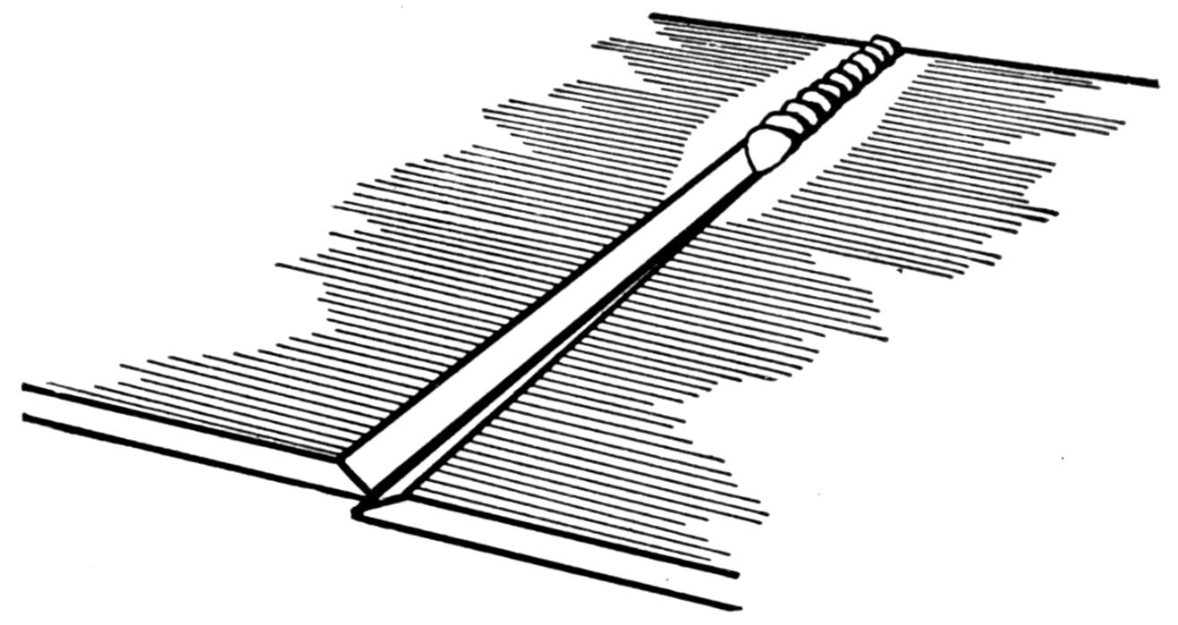
Fig. 61.—The Open Ends on long Steel Welds will Overlap as the Welding Progresses if Improperly Started.
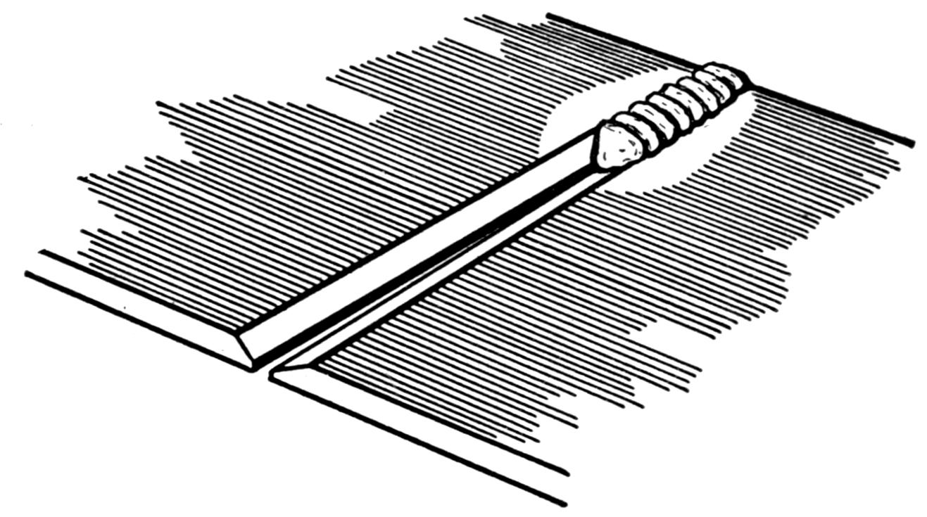
Fig. 62.—Showing how Open Ends of Steel pieces are Spread Slightly to Overcome Lapping of Ends in Making Weld.
(95) In welding on sheet iron and steel, many operators will find that they have more difficulty in executing a successful weld than on slightly heavier work. This is no doubt due to the thin nature of the work and the ease with which it may be burned or carbonized if the operator is not alert. When working on such material a very small filler-rod is used if thought necessary but this rod must be as free from impurities as possible. When working on a long seam such as may be encountered on a steel tank, it will be noticed that in welding from one end along the seam that the metal ahead of the flame will tend to overlap as shown in Fig. 61. This may be overcome by tacking (that is, fusing[90] the metals together), at various points before starting the weld, or the parts ahead of the torch can be separated as is shown in Fig. 62 and held this way by using a wedge. This is moved along as the weld advances and permits the edges to close together. Another method used by manufacturers who make a specialty of this work is to construct a jig which clamps the ends rigidly and they are welded while in this position. This phenomenon in steel welding will appear rather strange to the welder who has had some experience on thin cast-iron work, such as oven doors and the like. In these he found that as his weld advanced, the welded portion before him would separate, and when he had welded about[91] four inches or so it would be necessary for him to jump his flame back to the beginning of his weld and heat up that portion, in order to close up the cracks before him previous to his continuing the work. This is illustrated in Fig. 63. This may be explained by the fact that steel is a very ductile metal and when it is fused, the expansion is taken care of internally by the two edges combining. Then, in cooling, the metal contracts, an action much more rapid in steel than in cast iron, and draws the edges of the steel plates past each other so that they overlap. In cast iron, which is rigid, the edges are expanded by the fusion of the metal and this space is then filled up with new metal, holding the edges apart. As the weld progresses the metal ahead of the torch is pushing out, and that behind is cooling off, which acts as a lever on each side to open up the unwelded ends.
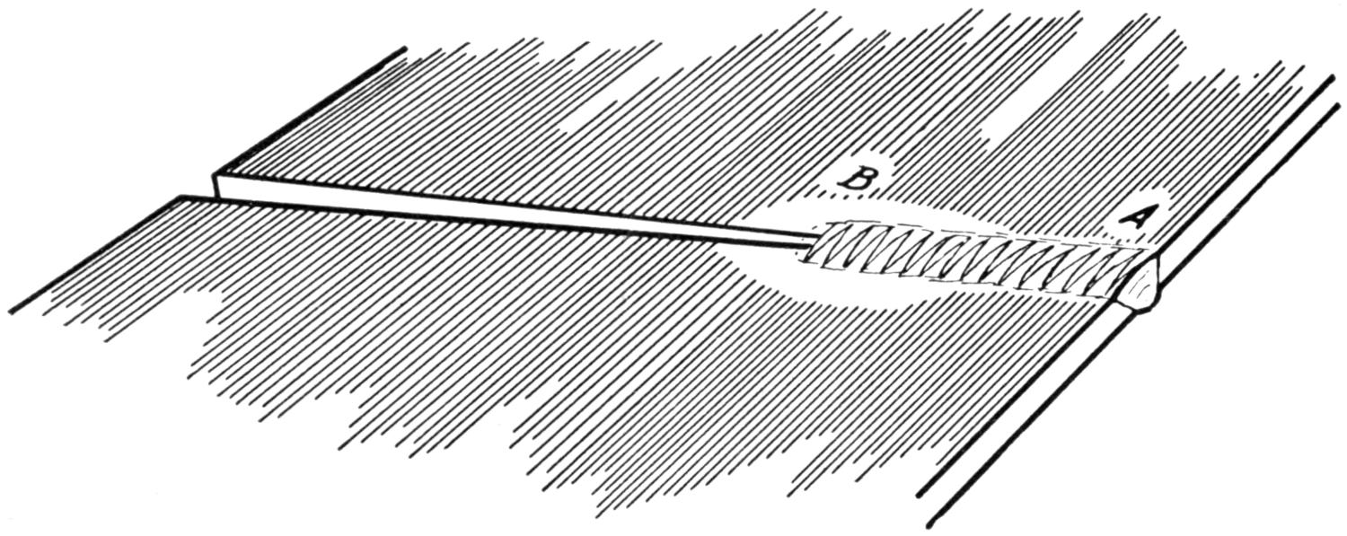
Fig. 63.—This Illustration Shows how the Open Ends of Thin Cast-iron Pieces Spread apart as the Weld Progresses. To Close the Edges together, Jump the Torch Flame from B to A; as A heats up, B Cools and the Lever-like Action Closes the Opening.
(96) To weld a broken automobile frame successfully the body of the car should be raised if necessary, to keep it from burning and all pipes, wires and gasoline leads protected with a covering of asbestos paper. Plenty of room should be allowed, so that the welder may have easy access to the break, and the frame should be jacked up on both sides[92] of the break until the frame is in proper alignment. Then weld the crack from the outside, working across the top, then down the side and across the bottom, reinforcing a little if necessary on all sides but the bottom. Then repeat this operation on the inside, reinforcing at all points. Then take a strip of steel about one-eighth or one-quarter inch thick and six or eight inches long and as wide as the bottom of the frame. This piece should be welded securely to the bottom of the frame with the former break in the middle of the strip. A cut representing this job is shown in Fig. 64. By this method the frame can be made stronger than originally.
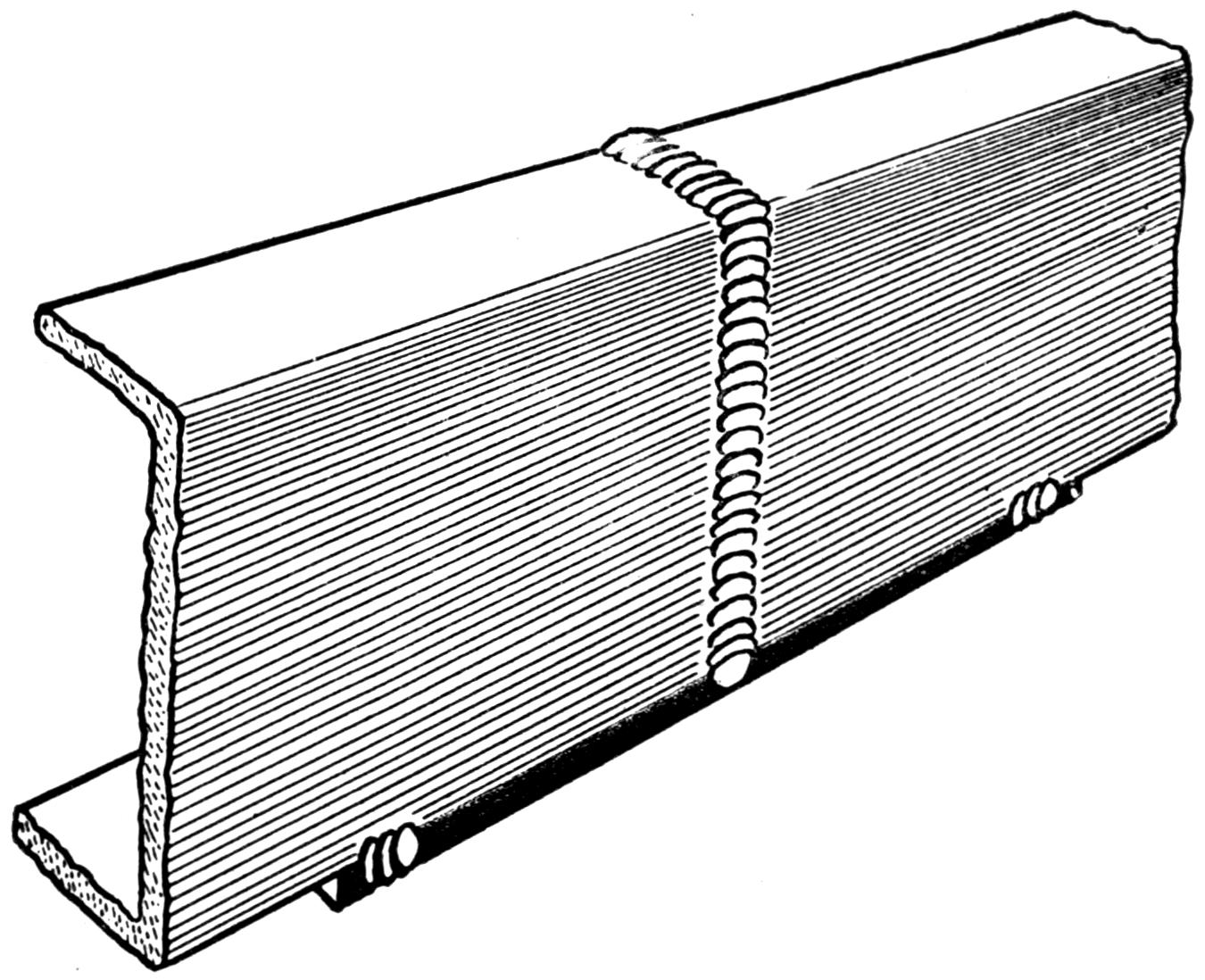
Fig. 64.—A Good Method of Reinforcing a Weld on an Automobile Frame is Here Shown. The Patch as Pictured Here is only “Tacked On.” It Should be Welded Securely to the Bottom of the Frame on all Four of its Edges.
(97) Aside from the difficulties already mentioned in steel welding, there are many others. A few of these will be taken up in order to let the beginner know how to approach the various problems which may confront him. But in no wise is this to be considered to be a treatise on advanced work. Ofttimes[93] the question arises, Can springs be successfully welded? Now, while springs have been welded, and they have been tested out thoroughly, yet the practice of spring welding with the oxy-acetylene flame is not to be recommended. There are those who will weld leaf springs, such as are found on automobiles, and will apply rapid blows with the hammer, while their weld is still in a heated condition and then plunge the spring in water or oil to harden it and the weld. A close observer will readily see why this procedure is not correct. Springs of this nature are made up of metal which takes a uniform hardening, and were it not so they could not be considered springs. Now, if there is a fracture and a foreign metal, which under no circumstances can be expected to take the same hardening as the rest of the spring, is introduced into the weld, it can easily be seen why a fusion of this kind is not to be relied upon. If it were possible to diagnose or take an analysis of the metal in the spring and use a filler-rod which, after being acted upon by the flame, would come out the same as the metal in the spring, then some success might be expected, but until that time, welding of springs will not be encouraged. Unless perchance the break is of such a nature that it can be reinforced readily and is in such a position that a resilient quality is not necessary.
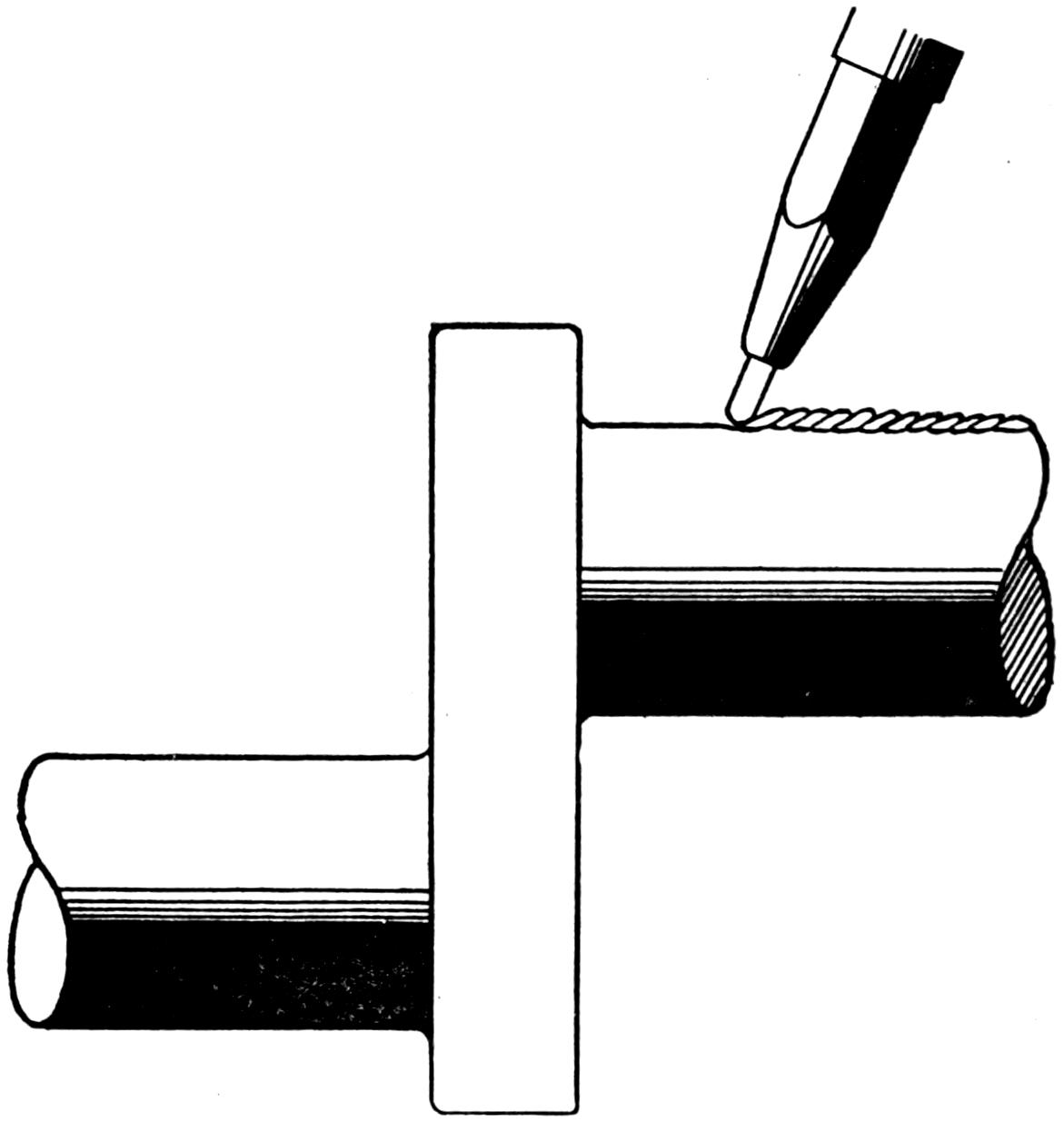
Fig. 65.—Building Up Worn Shafts.
(98) Work on crank-shafts often causes perplexity on the part of the beginner, for he usually hears this matter discussed pro and con. Crank-shafts of four inches in diameter can be successfully welded with the oxy-acetylene flame, and even larger, if correct methods are employed. There are many points which the welder considers before deciding whether a weld of this nature is advisable. Of course the usability of the piece after it has been welded is the main issue when executing any kind of a repair job. Now, a crank-shaft will generally break in either of two ways; by some external force, such as a connecting rod breaking loose, or by crystallization, which is usually due to fatigue. Now, in the latter[94] case, ofttimes the shaft will break in the cheek of the “offset,” and possibly no part of the shaft is thrown out of alignment. When such is the case, welding is usually recommended and the shaft may be brought back to a useful state in very quick order. However, in the former case, the shaft is apt to be sprung, and while it could be welded, the machine work necessary to restore it to normal requires much time, and it has been known, where after spending a matter of days in trying to get proper alignments, work was scrapped as useless. So it is entirely up to the welder in work of this kind to determine whether the job is worth while or not. There are certain parts of a crank-shaft upon which welding work can be done with a marked degree of success, such as building up worn bearings and the like. In doing work of this kind it is recommended that the welder fuse his metal in a line parallel to the center line of the bearing, seeing to it that he has a perfect fusion between the surface of the bearing and the metal he is fusing and adding plenty of metal, to insure enough being used, so that no low spots will show[95] up when it is machined. It is considered that by adding the metal as suggested the welder will hold his heat much better than if he attempted revolving the shaft continually. Fig. 65 will show the method here outlined in a very clear way.

Fig. 66.—Shaft Broken at End of Square Shank, its Weakest Point.

Fig. 67.—Broken Part of Shaft Removed and New Piece Added, thereby Moving the Weld away from the Weak Part.
(99) When working on shafts the welder will encounter such articles as automobile propeller shafts and rear axles, which generally break adjoining the square ends. He will no doubt wonder whether it is advisable to weld this square end back on, or whether to try and build up the shaft the desired length. Undoubtedly the point of fracture is the weakest portion of the entire shaft, else it would not break there. The execution of a weld at this point where no additional metal can be added or any means of reinforcing used is not to be recommended. Fig. 66 will show the problem which confronts the welder, and Fig. 67 the suggested means of overcoming the difficulty. By removing about four inches from the broken end of the shaft and adding a new piece, about ten inches long, of the same diameter, the weld will be removed from the weak point; a heavier weld can be made, and the end can be machined off to the desired size. This procedure is recommended on all jobs of like nature.
[96]
(100) Occasionally case-hardened ring gears are brought to the welder to have teeth built up or new ones added, and although the welder must realize that the hardening is destroyed by the action of the flame, yet he does not understand why it is necessary to reharden the gear. A little thought on this subject will make him appreciate the fact that if he destroys certain properties in metal which have been introduced for a reason, these must be replaced if he would bring the job back to normal. It would be like heating up a tempered lathe tool, or cold chisel for that matter, and trying to use it before it had been retempered. Therefore if hardening or temper is destroyed by the flame it must be restored.
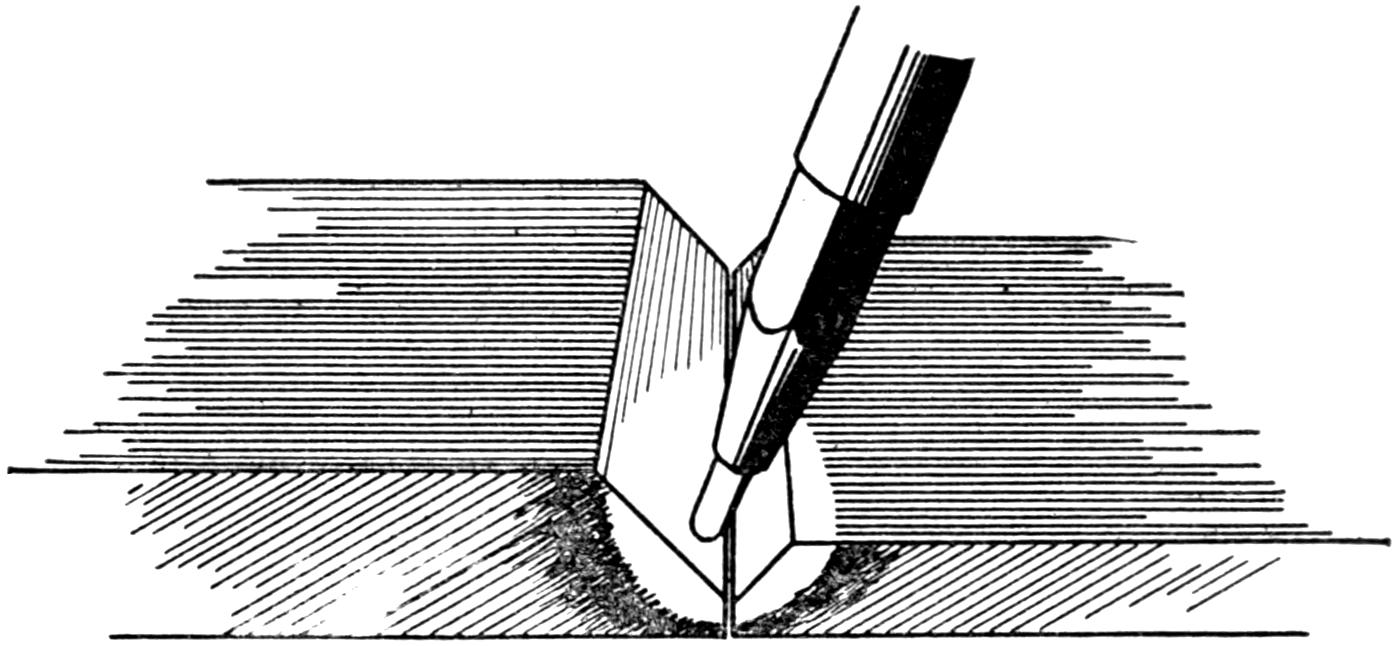
Fig. 68.—When Welding a Small Section to a Larger One, the Flame of the Torch is Directed toward the Heavier of the Two.
(101) If a weld were to break, it would be necessary for the welder to remove all metal added in the first weld before attempting to reweld. This is true of his own work as well as that of others which he may be called upon to do. For no matter how good the surface may appear, without a solid foundation no weld is of any value, and unless he clears out all of the old metal he cannot be sure of the work. This will apply not only to steel work, but to all metals, and it is a point which should be borne in mind.
(102) At times there are jobs come up in which one piece[97] of work is to be fused to another which is much larger, and will absorb much more heat during the weld. When handling such work, it will be necessary to play the torch upon the larger piece most of the time, as shown in Fig. 68, in order to bring both pieces to a fusion point at the same time and keep them in that condition.
(103) Once in a while it will be necessary for a welder to fuse cast iron to steel or vice versa, and the question will arise as to which filler-rod he will use. It has been found that a cast-iron filler-rod can be used with success and of course when using a cast-iron filler-rod, a cast-iron flux will be necessary. Work of this nature is not very frequent.
(104) When steel is in a melted condition, it seems to be in a very susceptible state. It appears to absorb gases, and with constant working an oxidation is in evidence which materially effects the strength of the metal. When working on vanadium and other alloyed steels, if kept in a molten condition too long, many of their principal characteristics are destroyed. For this reason it is advisable to execute steel welds just as rapidly as possible. While this is true of most work, it is especially to be emphasized on steel. To assist the welder in executing welds on large steel castings, the pieces are generally preheated, so that the work will take less time, be more successful, and save both oxygen and acetylene. When working on preheated jobs, in order to get the desired angle on the filler-rod so the welder may use it without discomfort, a light heat is played on the filler-rod, a matter of six or eight inches from the end being fused and then bent to an angle of 90 degrees, so that the operator may hold the rod at some distance from his work and still introduce it in the manner he desires. Some operators weld their cast-iron[98] filler-rods together, to get the desired angle as shown in Fig. 69, but this is not as common as the steel method, probably because cast iron will not bend and it requires some time to weld the rods together in this manner.
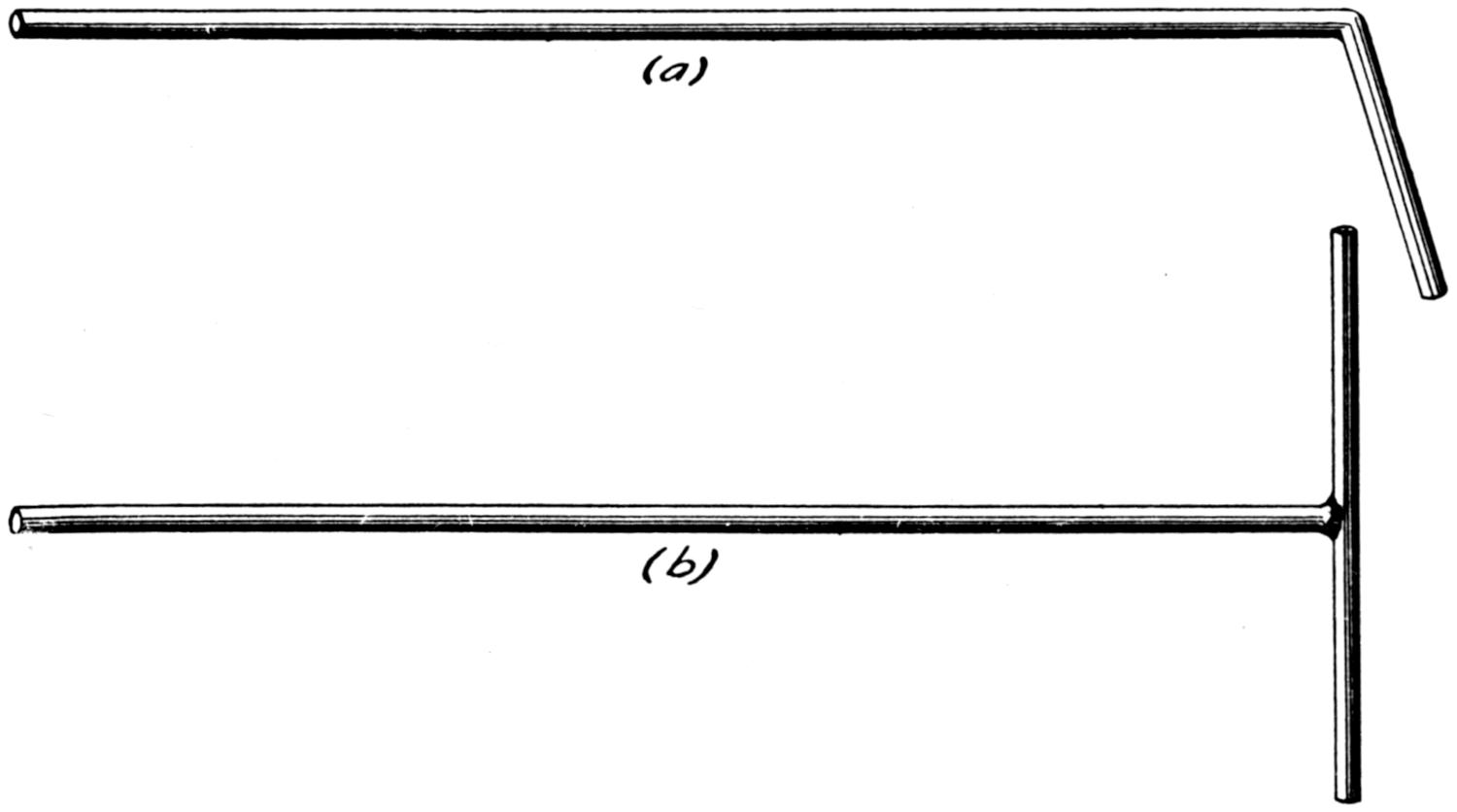
Fig. 69.—Kinks for Handling “Filler-rod” on Large Work to Remove Welder’s Hand away from Heat of Flame.
(a) shows how the steel “Filler-rod” is heated by the torch flame about 6 inches from the end and bent to the angle desired.
(b) illustrates how cast “Filler-rods” are handled. Since they will not bend, they are welded in the T shape shown. First one side is used in fusing, and then the other.
(105) In some parts of the country boiler flues are acted upon and eaten away by the impure water used, and when high prices prevail, retipping is generally resorted to. A simple method in which they can be satisfactorily and cheaply done is as follows: Cut off the poor end until solid metal is reached, with a pipe cutter, which will tend to “V” the work as it cuts and at the same time will squeeze the edge of the pipe in. After cutting, this end of the flue is placed on the horn of an anvil and the burr on the inside, which has been made by the cutter, is flattened out. It is very important that the flue be of the same size throughout in order to permit its being cleaned. It is then placed in “V” blocks or a[99] trough, made of angle iron, such as shown in Fig. 70, and the new end which has been prepared in much the same way is placed in the position shown in A in the same figure. The piece is tacked on at two or more spots and then laid aside until the whole set of flues has been prepared in this manner. Then they are replaced in the trough and welded, one after another, being turned at one end by a helper, thus allowing the welder to do continuous work. Care must be taken at all times that perfect fusion takes place between the flue proper and the piece being added, yet at no time should the metal be allowed to run on the inside of the pipe. More metal can be added than is really necessary and can later be dressed down on a grinding wheel to the desired size, which must be such that replacement of the flue can be made. Various-sized pipes can be welded in much the same way where no reducers are obtainable, the only change being that there must be a step made in the trough which will permit the various-sized pipes being lined up correctly. Jigs for the speeding up of manufactured articles which are to be welded are always being brought out by the ingenious workman and are to be encouraged whenever possible.
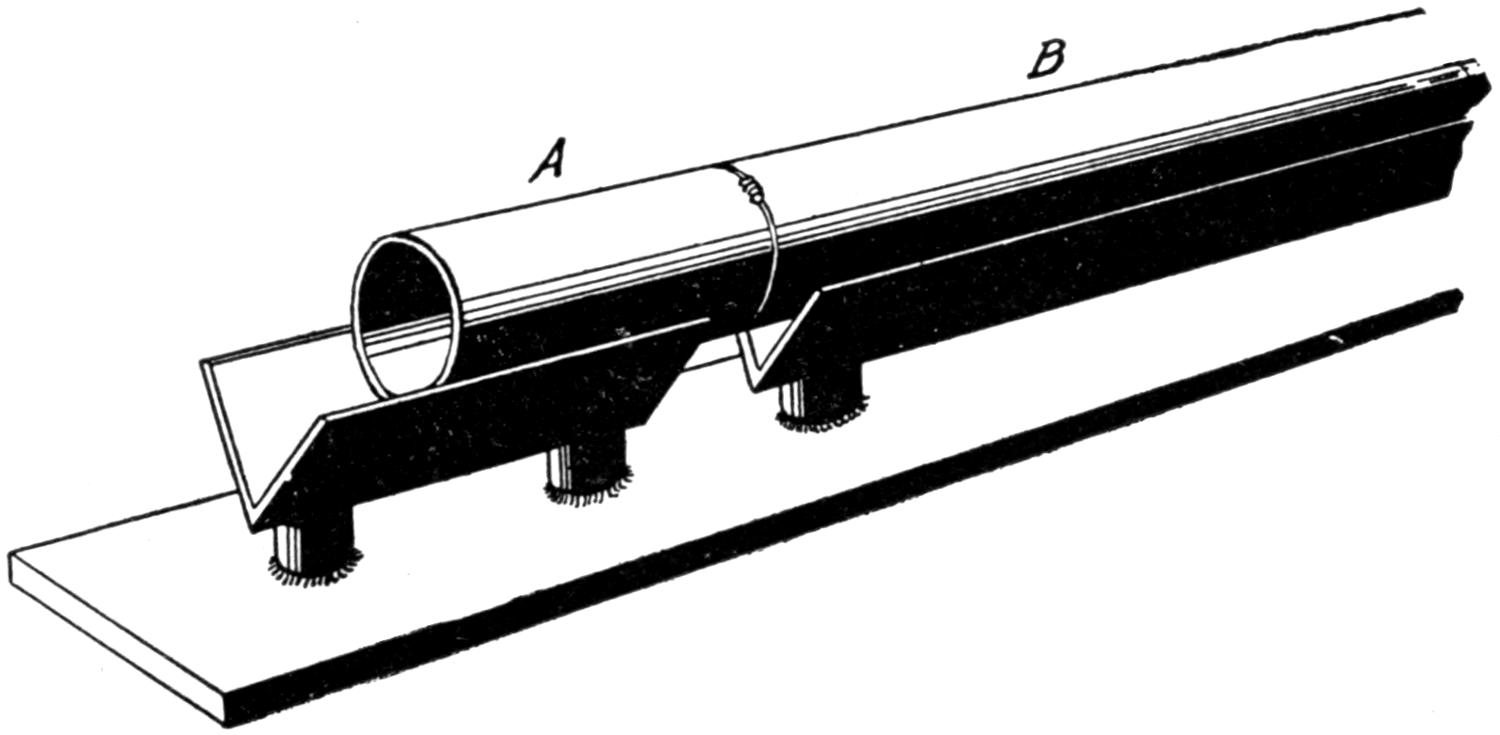
Fig. 70.—Showing a Simple Way to “Line-up” Flues when Retipping. B Represents the old Flue, and A the New Piece to be Added.
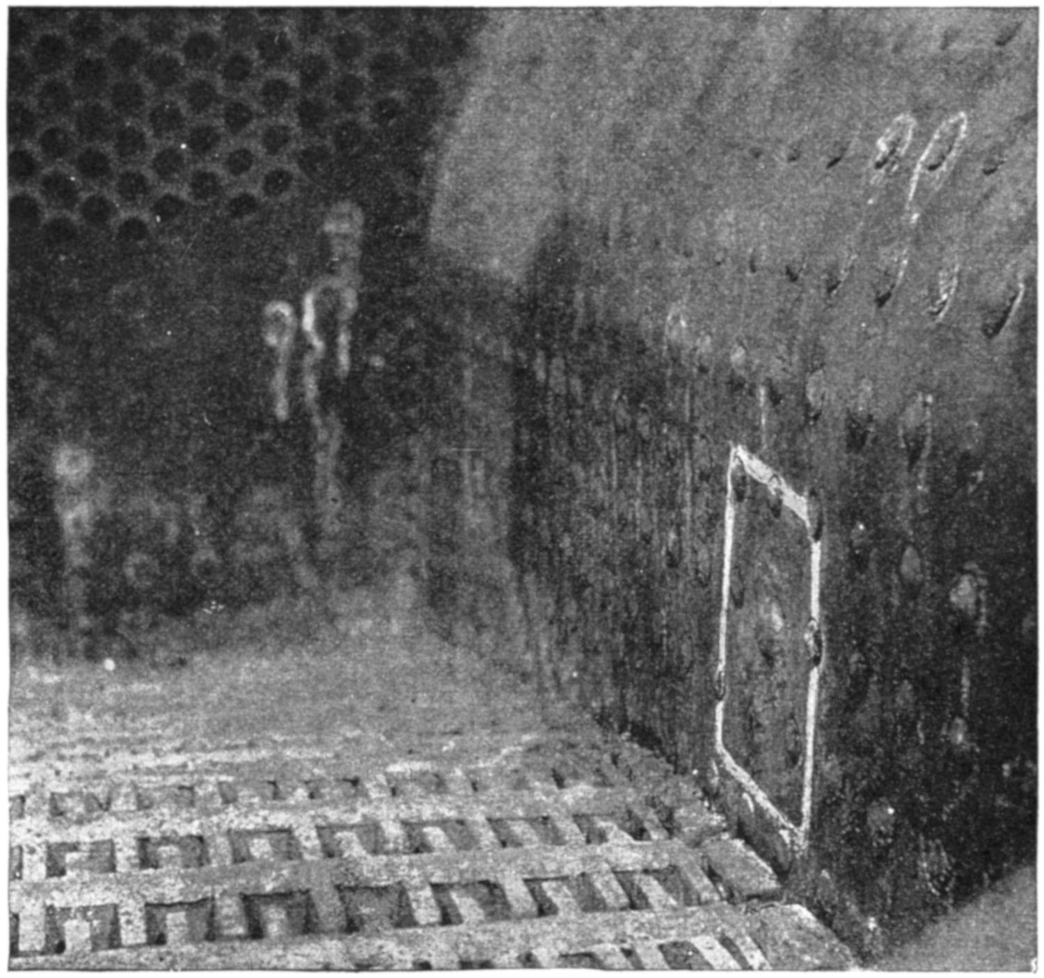
(Courtesy of the Oxweld Acetylene Co.)
Fig. 71.—Welded Cracks between Staybolts.
(106) In the repair of boilers many a feasible job has[100] been given up as impossible by the unthinking welder. Cracks have been found in fire-box sheets around the staybolts which, as soon as they are touched with the flame, seem to run and keep running. They really discourage those who are not familiar with this class of work. Many such welds have been executed and are apparently all right until tested, when they give way and make the job worse than it was previously. The trouble is in these instances that the welder has made no provision for contraction and while the job might appear to be successful, yet the internal strains exerted will not show themselves at the test. Many boiler[101] shops have found that the flat patch is not to be relied upon and when a crack is found between two stay-bolt holes, such as shown in Fig. 72, a round hole is cut as shown by the dotted line. A circular plate is then cut slightly larger than this hole and after being brought to a red heat, it is bellied by the use of a hammer or a set of dies, so that it assumes the shape of a saucer and is called by many a “dished” patch. Some idea may be had of such a patch from Fig. 73.
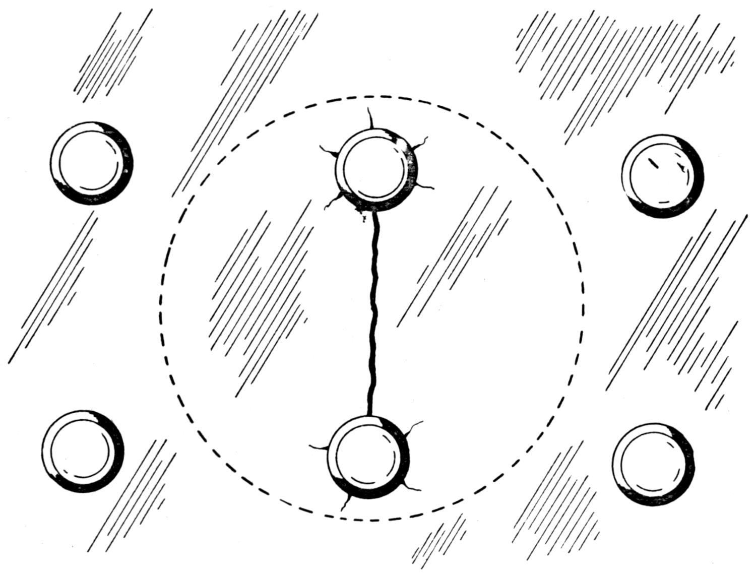
Fig. 72.—A Crack between the Staybolts in a Boiler should be Cut Out as Shown by the Dotted Line, to Prepare it for a “Dished” Patch.

Fig. 73.—A “Dished” Patch.
(107) The patch is placed in the sheet with the concave side toward the operator and should be securely welded in place, adding as little metal for reinforcement as possible,[102] but seeing to it that a perfect fusion is made between the patch and the sheet all the way through. As soon as the weld is complete the torch is played upon the high part of the patch, which is protruding, and as the weld cools off, sharp quick blows can be applied to the center of the patch, which should be kept in a heated condition until it is nearly flat. This will take care of any contraction that might set up and is a very good way of handling patches which do not exceed six or eight inches in diameter.
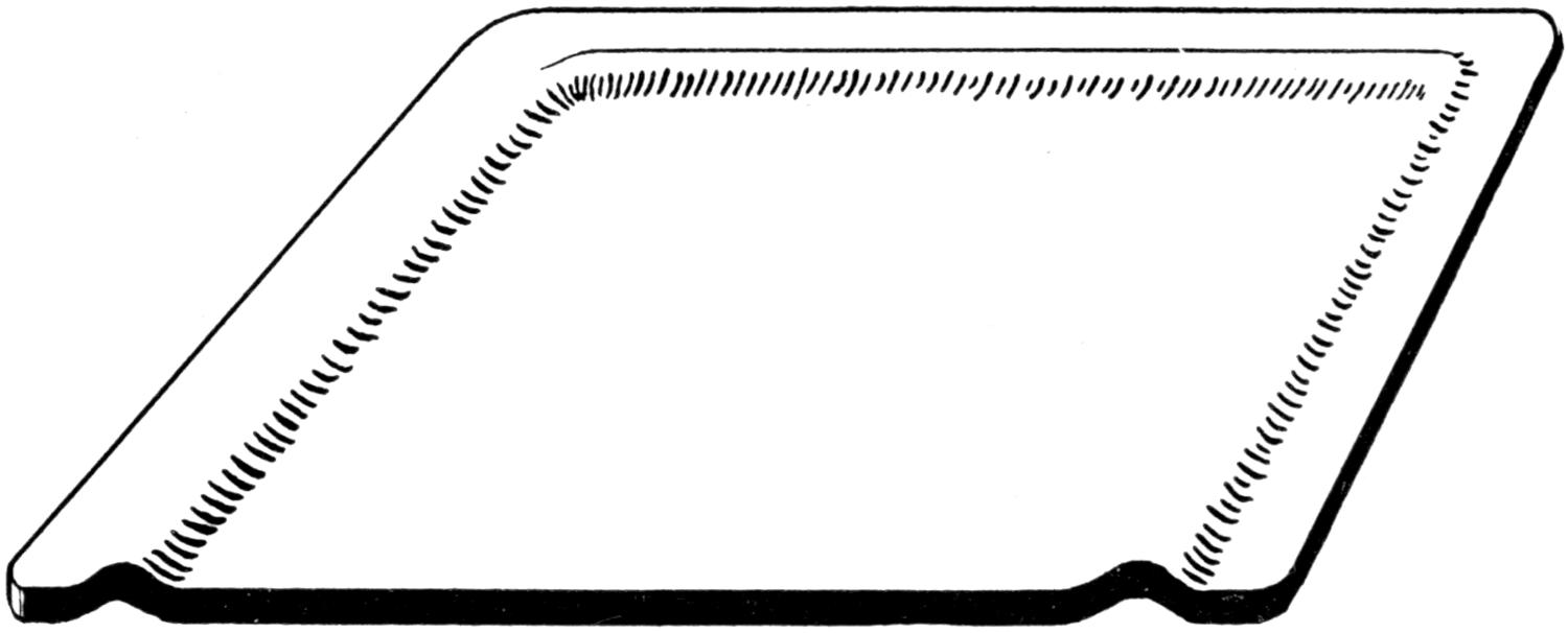
Fig. 74.—A “Corrugated” Patch.
(108) A “corrugated” patch has been brought out more recently than the “dished” patch, and as its name would indicate, it has corrugations around at least three of its sides. While a “dished” patch is limited in its scope and cannot be applied to square holes unless the square holes be cut round, the “corrugated” patch knows absolutely no limits as to size or shape. While its preparation is probably more difficult, yet its purpose is the same, that is, to take care of the contraction which takes place in sheets of metal where heat has been introduced. To prepare a “corrugated” patch, a piece of metal which is somewhat larger than the hole is taken and the corrugation is made by placing two rods on one side and somewhat separated and between them on the other side another rod. With this section of the patch heated to a red heat, a drop hammer is played upon it and[103] a corrugation effected. Or an easier method is by the use of specially prepared dies, which will turn out a patch in quick order. It must be remembered that while the patch shown in Fig. 74 is only for a very simple job, which is rectangular in shape, yet “L” shaped patches can be prepared and handled in the same manner. When the corrugation has been introduced into the patch, the latter is cut so that it will fit the hole, and it is tacked in position with the bellied sides out. The method used in applying a patch of this kind is to weld the uncorrugated side, then start up the corrugated side and weld for two or three inches, then play the torch upon the corrugation, adjoining the part welded, and slightly hammer to assist in the expansion of the same; then return to the weld, continuing it until the corrugation can again be played upon. By doing this, when finished the patch will be flat and no signs of the corrugations will be shown. While many patches of this nature are in use giving the very best service, the welder who looks upon the finished job cannot tell how it has been accomplished.
(109) While the methods here given seem only to apply to boiler work, they are not so restricted and can be applied to tanks and various vessels with success. However, when welding on tanks which have contained inflammable gases or gasoline the welder is cautioned to take every measure to safeguard himself, and while it is known that much work is being done on such jobs, it is not recommended and in fact quite the contrary. It is true that there are such methods as filling the containers with water; cleansing with live steam, and so forth, but the cautious man will refrain from working on these vessels even though such measures have been taken. Gasoline has a faculty of penetrating the pores of metallic surfaces, and although these vessels have been emptied and have remained so a matter of a year, the gasoline is still present to some extent, as is evidenced by the[104] fact that as soon as heat is applied and the molecules of the metal are expanded, the gas is released in sufficient quantities to cause an explosion. This is not in one instance only, but in many, so it has been thought best to discourage any welding work on vessels which have contained gasoline at any time.
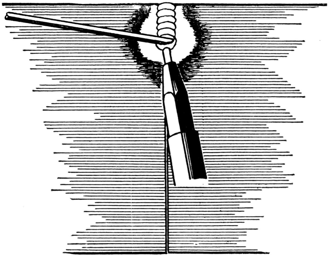
Fig. 75.—Working a Vertical Weld on Steel, from the Top Down.
(110) While it is possible to weld cast iron on the vertical, by the use of carbon blocks and so forth, the same kind of work can be accomplished on steel with much ease, without the use of any blocks, or materials other than the filler-rod and the welding torch. There are two methods of handling vertical welds; welding from the top down, or starting from the bottom and working up. The former seems to be condemned by those who have never tried it, on account of the carelessness which is apt to be used on work of this kind. However, for the beginner, it is thought advisable to teach this method, as there are many places where it can be used advantageously. The metal at the top of the seam, such as a broken automobile frame, or the like, is brought to a molten state and held there, not only by the velocity of the flame, but also by the filler-rod, as is shown in Fig. 75. With the[105] choosing of a tip of the correct size, the melted metal can be held under control with much ease, after a little practice, and it is allowed to descend as soon as the metal below it is in the proper shape for fusion. The filler-rod is added continually, for it is never lifted out of the molten metal, merely stirred a little from side to side as it descends. None of the melted metal is allowed to precede the flame, and at all times the operator can see whether the edges to be fused are at the right heat. As soon as the bottom is reached, the weld can again be gone over if it is not thought strong enough, and reinforced as much as desired. As soon as the operator is familiar with this method, he will find that much more speed can be developed, less filler-rod lost and less lapping done than by building up from the bottom.
(111) In welding over head there is a tendency on the part of most welders to avoid the use of enough heat to bring their metal to a molten state, for fear that it will drop upon them. It must be remembered that lack of heat means poor welds and that the metal must be in a molten condition whenever the weld is to be made. As soon as a little practice is given to this kind of work, the welder will see that the melted metal can assume some proportions without dropping off, despite its weight. It has probably been noticed that on “sweating” water tanks drops of water accumulate on the bottom of the tank and do not fall off. It is the same sort of problem in the case of melted steel. The adhesion of the molecules and the surface tension are the forces that keep the metal from dropping.
[106]
(112) It is difficult for the beginner to accustom himself to brass welding, especially on large work. While he has been taught to believe that brass has a much lower melting-point than iron or steel, yet when he comes face to face with the actual problem of melting it, he will find that it is necessary to hold his flame in contact with his piece much longer, on brass work than on either of the other two, before the melting point is reached. This can be accounted for by the great conductivity of brass. On cast iron and steel the heat was rather local, but on brass work it is transmitted to all parts of the piece as rapidly as it is introduced, and this absorbing process continues until practically the entire piece is near the melting point.
(113) Brass has for its base, copper to which an alloy of zinc has been added. Now the most difficult part of fusing brass work, is to add more metal from the filler-rod to the parts which are to be fused, without burning up any more of the alloy, than is absolutely necessary. Seeing that the copper and zinc have different melting points, it is a very difficult feat and requires considerable practice. Much of this trouble can be eliminated by the use of a filler-rod which has the correct proportion of alloy added, so that it may take care of and replace any that has been destroyed by the flame.
(114) Brass work is “V-ed” out when welding is to be done, in practically the same way as cast iron. Only under no circumstances should the ends of the parts be burned[107] off, when “V-ing,” as the heavy oxide which is deposited on the remaining metal is very hard to combat with the welding flame. The ends of the work are brought to a red heat with the flame that is slightly carbonizing. This is held directly in contact with the work during the preheating stages, in much the same manner as on cast iron, and a small layer of carbon may be seen to accumulate around the weld. Now, in theory, this would seem the worst thing possible to have present, but in practice a small quantity of this soot acts as an aid in making the weld, besides making the flame less intense, which saves much of the alloy, from being burned when the fusion occurs. When the ends have become red hot, the same procedure is used as in working steel, except that the torch is given a slightly greater angle and a brass flux is used.
(115) Contrary to most authorities we find that an abundance of good flux is desirable on brass work and that it is almost impossible to use too much. It is desirable to use only the best welding fluxes, for the best welds are to be insured only under ideal conditions. If a welder were to run short of flux, however, he might use powdered borax of the 20 Mule Team variety, to tide him over until he could get a new supply. The flux is added in the same way as the cast-iron flux, that is, by dipping the heated end of the filler-rod into the flux container. Enough will adhere, and when added will clear up the metal in the vicinity of the weld. It should be added as often as a welder notices his metal needs cleaning and this will vary depending upon whether there is a slow or rapid worker behind the torch. A man must use his own judgment in cases of this kind. Remember that the flux is a cleaning agent and if the surface is clean, no additional flux is necessary, but if the contrary is true, that is, if the surface is full of oxide and the filler refuses to flow easily, flux is necessary and should be added.
[108]
(116) During the welding, dense white fumes will come from the fusing brass. This is the burning out of the alloy, that is, the zinc. These fumes are injurious to the welder and should be avoided, if possible, by proper ventilation. The use of a proper filler-rod and rapid work will largely tend to overcome the presence of these fumes, but if the operator is very slow, they will appear, and are followed by a porous and brittle weld, which if broken afterwards will show a large number of blow holes. The most difficult part of brass welding as a whole is to add the filler-rod, being certain of a fusion, without burning out the zinc. When brass is in a heated condition, it is very fragile and will crack readily if disturbed. All precautions should be taken to see that no sudden jarring is given the piece until the weld has completely set. When this work is done many welders plunge their work in water, in an effort to make it more ductile and easier to machine. While this, of course, is condemned by theorists and rightly so, in practice there seems to be no injury results.
[109]
(117) So far as the actual fusion of aluminum is concerned, it is probably more easily learned than any other metal, but on account of the rapid conductivity of heat and the loss of most of its strength when heated, aluminum has caused much concern among oxy-acetylene welders.
(118) There are two methods used in welding aluminum, the flux method and the puddle method. The puddle system gets its name from the use of a puddle stick or spoon-like rod which is used to stir the metal together, and is very satisfactorily used on all cast aluminum. The flux method is applied to both cast and sheet aluminum and it is so-called because a flux is used to break up the oxide along the line of weld. The discussion to follow applies only to cast aluminum. It is in this metal that most interest is centered, as the welding of sheet aluminum, such as is found in automobile bodies and some cooking utensils, is not encountered in the ordinary run of work.
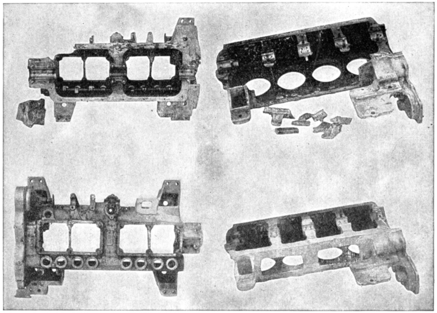
(Courtesy of the Torchweld Equipment Co.)
Fig. 76.—Showing Aluminum Crank Cases Before and After Welding.
(119) When working with the flux method about the same
sized tip is used as when working on cast iron. This is applied
to the line of weld and held there until the oxide on the surface
commences to wrinkle and small globules of a mercury-like
appearance form on the surface. When heat is introduced
in aluminum it is transmitted throughout the piece
in the same manner as occurs in copper and brass, therefore
it will require much more time to heat the work than the same
sized piece of cast iron or steel. As soon as the weld assumes[110-
111]
the condition mentioned, fast work is necessary or the metal
will collapse, for it loses most of its strength when heated to
this condition. The end of the filler-rod bearing the flux
is brought down on the metal and immediately the surfaces
will clear up and run together, like so much mercury. The
torch is instantly jerked away and applied farther along the
weld. The theory of this reaction is that the heavy aluminum
oxide is the only thing which prevents the metal flowing
together when heated, and as soon as the flux is introduced
this oxide will be destroyed along the line of weld and a fusion
of the metal effected. This actually takes place, providing
enough heat has been introduced to permit this reaction to
penetrate the depth of the weld. The flux contains the
chemicals necessary to cause this reaction if the metal is
in the right condition. There are many welders who do not
use sufficient heat and blame the faulty results upon the
flux. On the other hand, there are many fluxes which are
absolutely useless in performing a function of this kind.
The chemicals necessary in compounding a good flux for
this class of work are expensive and therefore this flux cannot
be procured at a low price. When the weld is finished and
cooled the surface should be scrubbed with soap and water
to remove all traces of the flux, otherwise a corrosion may
occur a month or so afterwards, and while it may not affect
the weld in any degree, the owner of the piece may not be
pleased at the sight. It is therefore advisable to remove all
traces of flux used on aluminum work.
(120) The puddle system differs from that of the flux, insomuch that when the metal has been brought to the same heat, where the flux has been applied it will be found that the metal is really in a pasty condition. It can be stirred together and the break entirely eliminated by the use of a puddle stick, either of a pointed or a flat spoon-shape design, as shown in Fig. 77. During this puddling stage,[112] the torch is usually held in the left hand with the flame some distance away from the work, only introducing enough heat to keep the puddle pasty. The puddle stick is handled by the right hand and when extra metal is needed the puddle stick is laid aside and the aluminum filler-rod is picked up and worked into the weld. When sufficient metal has been added the puddle stick again comes into play and can be used in stirring the metal together and finishing it off in the desired manner. Reinforcing the weld will apply to aluminum the same as every other metal, and a very neat job can be made after a little practice with the puddle stick. At times some of the aluminum may adhere to the stick, which is made from a quarter-inch piece of steel filler-rod, but this can be removed by scraping it upon the fire bricks which should be in the vicinity of the weld.
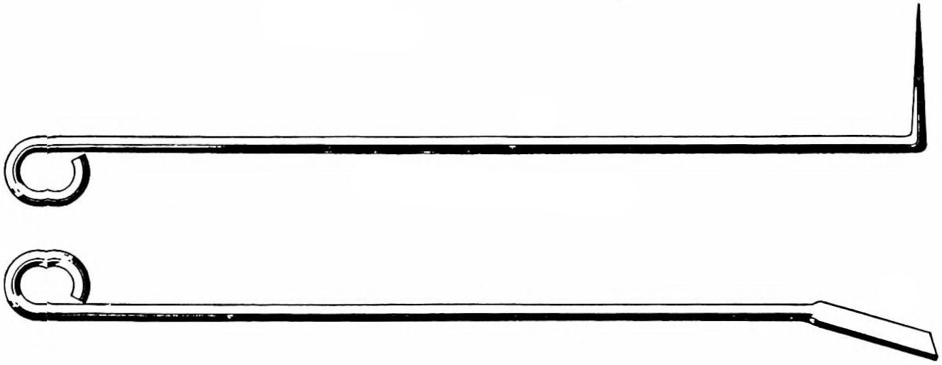
Fig. 77.—“Puddle-sticks” for Welding Aluminum.
(121) There are two kinds of filler-rods used in aluminum welding. Both are aluminum, but one is cast and the other is a drawn rod. This same difference will also be noticed in bronze filler-rods, and there has been much discussion as to which is the desirable one to use. Neither of them is supposed to be 100 per cent pure aluminum, as such a filler-rod does not give the desired results under the action of the[113] flame. A matter of from 90 to 95 per cent aluminum, with 5 per cent to 10 per cent of copper present as an alloy, is found to make a stronger and more successful weld. It is recommended, if possible, to use the drawn rods whenever available; for a weld at best is only a casting, and if this casting can be made from virgin metal, rather than recast from metal which has been cast many times and the contents not known, it is thought that the results will be far more satisfactory. A weld made with such a filler-rod, care being taken to work out the oxides, will compare very favorably with the strength of the original metal and in many instances a reinforcement will make it much stronger.
(122) To combine the two methods of welding aluminum is not recommended. If the flux were stirred up inside the weld with a puddle stick an unsatisfactory weld would result, so they are to be kept entirely separate. It is not necessary to “V” out aluminum for the same reason as other metals are “V-ed” out. When it is in workable condition it can be puddled and stirred about as desired. It is well, however, to “V” out slightly for the sake of marking the line of weld. When aluminum is heated up, the expansion which occurs may close up the crack, which was previously quite visible, in such a manner that it cannot be located without much loss of time. Ordinary chalk or soapstone, if available, may be used to mark any preheated work, but the use of a chisel along the line of weld is the most reliable method.
(123) It will be noticed, when welding aluminum, that bright surfaces will oxidize immediately when exposed to the air. This action occurs perhaps faster on aluminum than on any other metal. With this oxide or scale present the metal will not run together nor fuse, no matter how much heat is[114] applied. The metal may be molten on each side of an oxidized crack and at times will cause the line of fracture to even float, but if the oxide is not destroyed the metal will not fuse. As has been noted previously, two methods are used to destroy this oxide, namely, the flux method and the puddle system. On account of this exceedingly rapid oxidation, it will be found to the operator’s advantage to complete his aluminum welds as quickly as possible in order that he will have less of this oxide to combat. It will be found in using the puddle system that greater haste can be made by using the torch in the left hand, leaving the right free to do the puddling and to add whatever metal is necessary. In this method most of the success depends upon the operator’s skill in handling his puddle stick and puddling in additional metal. Generally the right hand can do this more rapidly than the left.
(124) It is well to learn how to make a successful weld from one side of the metal only, and while this will apply to all metals, it is especially advantageous in working aluminum. Where a small layer of metal has been added to one side of an aluminum job, such as a crank case, and it does not penetrate the entire thickness of the metal, when the other side is turned, and the flame applied to it, a difference in temperature and the loss of strength in this metal when heated will cause the first side welded to crack unless the operator is extremely cautious. Therefore it is always well to learn how to penetrate the entire thickness of the metal from one side and make a satisfactory weld in this manner.
(125) As previously stated, aluminum when melted loses most of its strength, and if not supported by some means or other the metal will collapse. On account of this it is advisable to back up aluminum work, when possible, whether the job is to be done cold or in preheated condition. The most successful manner of backing up is shown in[115] Fig. 78, wherein A represents a thin sheet of copper which has been fitted to the work, and daubs of asbestos cement shown at B will aid to some extent in holding the plate in position, but this alone should not be depended upon. A prop or fire brick, upon the top of which has been placed a cushion of cement, will serve as a good backing, but where this cannot be accomplished filler-rods may be bent in the manner shown in Fig. 78. These filler-rods are not of the springy type, but are of soft wire and the loop as shown is not for a spring effect, but merely to take care of the contraction and expansion of the wire. Copper is given a preference over most of the other sheet metals, because it can be peened with a hammer to any shape desired, and many odd shaped additions can be formed by its use.
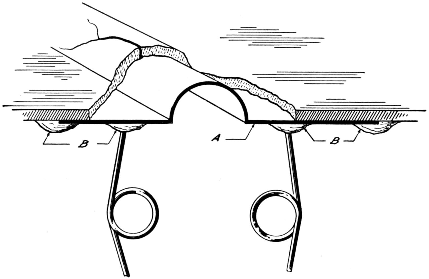
Fig. 78.—One Method Used to “Back Up” Aluminum Work, when Welding. A Represents a Sheet of Copper; B, Asbestos Cement.
(126) The use of clamps, when working on aluminum, is not recommended on account of the great conductivity of heat and the weakening of the metal as it approaches the melting-point. Pressure of any kind is not desired and the[116] operators who attempt to use clamps will regret it sooner or later.
(127) In aluminum work contraction and expansion take place the same as in other metals, only to a much greater extent, and greater allowances must be made. However, the same rules can be applied when determining whether work should be preheated or not, for if the ends are free to move, the work can usually be accomplished without preheating, whereas if confined, it will be necessary. When preheating is necessary the whole piece must be treated in the same way, regardless of the size. If only part of the work were preheated and the balance left exposed, it would be almost impossible to avoid warpage and shrinkage strains, which would render the work useless. Always preheat the entire piece if any portion requires it.
(128) Great care must be exercised when setting up aluminum work for preheating. Its weight should be distributed equally on whatever support is used, so that there will be no danger of any one part sagging, thereby throwing the whole piece out of alignment. A good way of accomplishing this is to lay fire bricks on their flat side, in such a manner that the weight of the work will be fairly well distributed. Then put a daub of clay or asbestos cement on each brick and press the aluminum piece down on this cushion. This will overcome the use of shims and other methods used for jacking up the work, which are unreliable.
(129) If charcoal is to be used as a preheating fuel, an oven of fire brick should be built up with draft holes in the bottom layer of brick, as described in the chapter on Preheating. A layer or two of charcoal is then ignited. The oven is then covered with asbestos paper or a piece of sheet metal. Asbestos paper is preferable as the metal becomes very hot and is apt to burn the operator. After the fire has received a good start, additional charcoal is added[117] until sufficient heat is obtained. This can be determined by sprinkling a little sawdust on the surface of the aluminum, and if it chars readily, the work is ready to weld. Other methods have been outlined previously, any or all of which may be used in learning this heat. In executing the weld as little of the work is exposed to the air as possible, in order to hold a uniform heat and not permit any part to become chilled. At the completion of the weld the oven is covered over, the openings in the bottom row of bricks are stopped up, and the piece allowed to cool with the dying fire. The charcoal process is the slow but sure method of handling preheated aluminum work, and is always recommended.
(130) When preheating aluminum with torches burning kerosene or gas a different kind of oven is built, as previously described in the lecture on Preheating. No openings are left in the lower row of bricks and the oven is built very much closer to the work being preheated. As the object is to confine as much heat as possible and have a uniform temperature throughout, it is not desirable to have such ovens loosely constructed. If the bricks are irregular, a double wall can be built with a layer of asbestos between them. Such a procedure is always recommended if time and bricks permit. A hole is left in one end of the oven for the preheating torch flame to enter. On aluminum work the flame is never played directly upon the metal. A baffling plate of metal or fire brick is used to distribute the flame around the sides of the piece and very satisfactory results may be obtained by preheating in this manner.
[118]
(131) Many times aluminum crank cases which have large holes punched in them and parts missing are brought to a welder for repairs. A question arises as to whether it is best to back up these holes and fill in the missing parts with a filler-rod as the welding progresses, or whether these parts should be cast separately or cut out of another crank case. It will generally depend upon the size of the hole, as to the desirable procedure in a case of this kind. It must be remembered that if the casting and welding are to be done at one and the same time each additional layer of metal must be fused to the last layer and that in reality a great deal of welding is necessary. In addition this added metal must be fused to the crank case. On small holes, perhaps two or three inches in diameter, this method is recommended, but if the hole is much larger, it is best to cast a piece and then weld it in, for in this instance there is only one line of weld to look after.
(132) On aluminum work it is proper to weld from the closed end of a crack toward the open, whether the piece has or has not been preheated. This is true also of all other metals, for if the weld were to be started at the open end and worked backwards there would certainly be internal strains set up, which would be undesirable. If it is not clear which end is the open one, the operator should stop a moment and figure it out.
(133) Were a suspension arm of the U type on an aluminum crank case to break about three or four inches from the body of the case, it could be welded in place without dismantling the motor, if handled properly. Free access must be had to the line of break, so that the operator can manipulate his flame at whatever angle he thinks best. Due to the contraction and expansion, which may throw the piece being[119] welded out of alignment slightly, it is best to blank the bolt hole at the end of this suspension arm and face it off, before the piece is welded in position. Later a new hole can be drilled which will line up accurately with the frame, and the welder will not then have to worry or attempt to return it exactly to its former position. In order to keep the case itself as cool as possible, wet asbestos should be packed around it, near the broken arm, so that too much heat will not be absorbed by it. The broken end is then tacked in position at two or three places and the weld started. On such a problem the puddle system will be found best, for both horizontal and vertical welding are to be done, as well as some overhead. As flux causes the metal to flow, it is rather difficult for the beginner to apply it to vertical and overhead work. The puddle stick should work through the metal its full thickness and eliminate every possible trace of the break, digging out the old metal where dirt is found, and adding new metal for reinforcing. When one side has been welded and reinforced it should not be allowed to cool while the other side is being worked. The torch should be played upon it every now and then, in order that the whole line of weld will be at approximately the same temperature; otherwise, the weld may break in cooling. The ease with which aluminum is puddled together, which many welders have likened to the children’s method of making mud pies, seems so simple to the beginner that he cannot see where the strength comes from when cooled. On account of this, he invariably works his aluminum too long. After welding a few test bars of this metal and breaking them in the line of weld, many old welders will gain confidence upon seeing the results of their own efforts.
[120]
(134) The welding of malleable iron, so far as the actual fusion of the metal is concerned, is not practiced except in very few instances, where the parts are very thin and have been completely annealed. This is on account of its being what might be termed a heat-treated metal. To begin with, malleable iron is cast iron, and becomes malleable only after it has been heated to the proper condition in the presence of material which will absorb much of its carbon content, and kept in this state until a suitable depth of its exterior has been annealed. It has been changed from a brittle casting to one which will bend to some extent without breaking, and its surface, by the withdrawal of the carbon, has been converted into steel. The interior remains cast iron. The depth of penetration will depend entirely upon the number[121] of hours the work is treated. Usually it runs from one-sixty-fourth to one-eighth of an inch, depending upon the type of work. An idea may be gained of how a cross-section of this metal will appear, by noting Fig. 79.
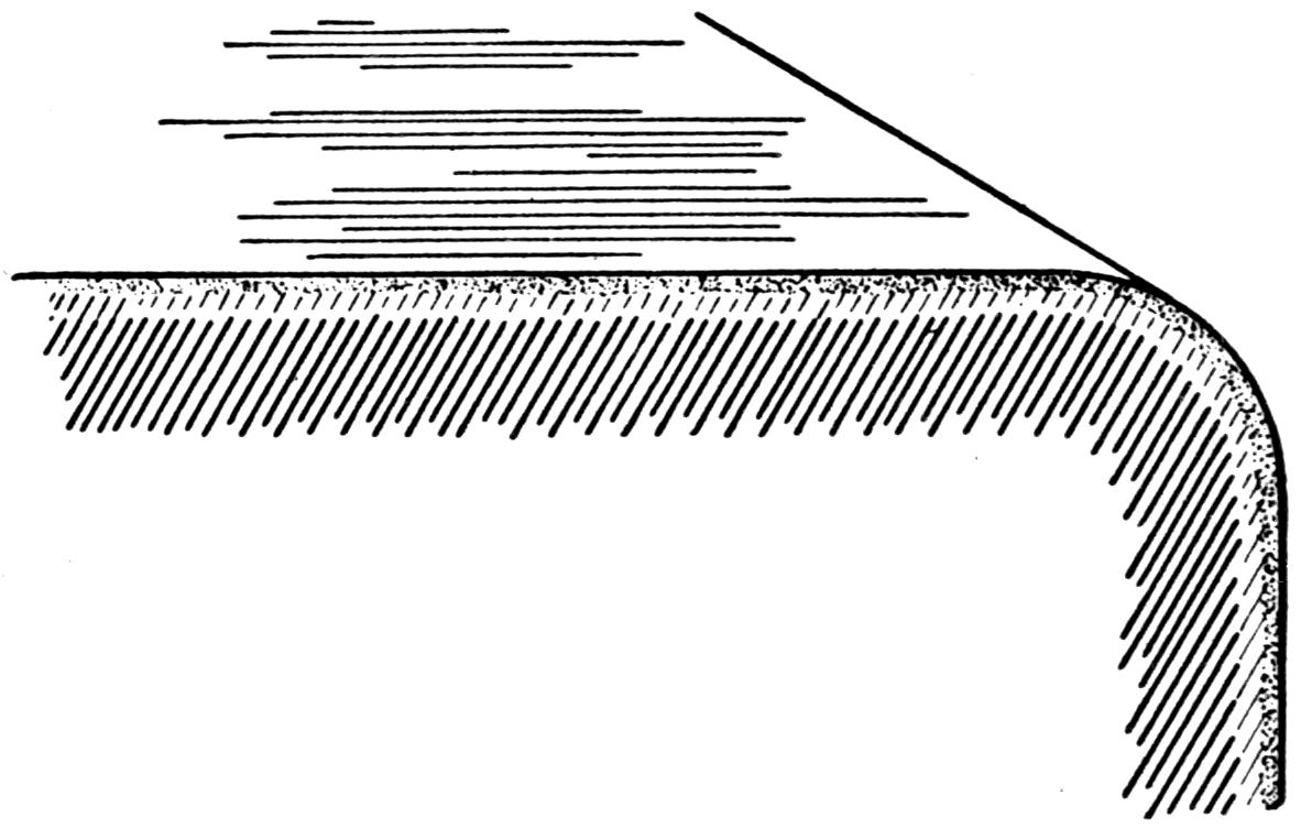
Fig. 79.—Illustrating Cross-section of Malleable Iron.
(135) A machinist would not think of destroying the temper in his tools and then attempting to use them without retempering them. So the welder will not attempt to melt malleable iron, for he realizes that if he were to attempt fusing this metal that its character would be entirely destroyed. If he should make a fusion, the weld itself and in the vicinity thereof the metal would be very brittle and retain none of its ductile qualities. When a weld of this kind is attempted, first, a few steel sparks are given off from the surface of the metal, which quickly diminish and the surface seems to recede from the flame. A white foam appears as the steel surface is burned and many small blow holes then make their appearance. The casting resembles a steel casting which contains much sand and impurities. The welding of malleable iron, in its broadest sense, is therefore not recommended, although as it has been stated there are occasions when it can be successfully accomplished. The best manner of bonding malleable iron is by the use of a bronze filler-rod, and this process will hereafter be referred to, for convenience, as welding, although it may resemble brazing in some respects.
(136) The art of welding malleable iron with bronze is not very difficult to learn. Possibly, the greatest trouble will be experienced by the beginner in distinguishing malleable iron from other castings. By again referring to Fig. 43 and carefully noting the various methods outlined, this trouble should be overcome. Many times, too, if the welder has had any mechanical experience, he can probably determine where the casting has been used and can ofttimes satisfy himself whether it is malleable or not. Malleable castings[122] are very seldom used as a wearing surface, and are generally employed where there is strain, to replace steel castings and forgings, which are much more expensive. If it has been determined that the metal is malleable iron, half the battle has been won.
(137) In preparing malleable iron, a clean surface is necessary in the vicinity of the weld. No “V-ing” out is necessary unless the piece is greater than one-quarter inch in thickness, and then the surface of the “V” should be as rough as possible. The ends are placed as close together as possible, the same as in brazing, and a welding tip which is one size smaller than would be used on the same thickness of cast iron is then used, with a slightly carbonizing flame. See Fig. 23. The work is heated, the same as in cast iron and steel. This flame is played directly on the work in a vertical position, similar to that used in preheating the weld in cast iron and steel, until heated to a cherry red, back about one-half inch on each side of the weld. As soon as this heat is obtained, the bronze filler-rod carries a quantity of bronze flux to the weld and this further tends to clean the surface. With the end of the filler-rod directly in contact with the work nearest the operator, the neutral flame melts the end of the rod, which immediately should run over the adjoining surface and through the crack. When this occurs the flame is abruptly twisted away from that portion of the weld to avoid burning the bronze. This is repeated along the line of the weld until the entire surface is covered with a thin coating of bronze. With this as a foundation more bronze is added, but during this process the torch is turned so that the neutral flame will not bear down directly on the bronze, which has already been added. It should rather strike it at an angle and radiate enough heat from the side of the neutral flame to permit a fusion between the filler-rod and the bronze already added. Much more surface should be covered and[123] more of a reinforcement made than in either cast iron or steel, in order to warrant enough strength for this class of work.
(138) A good bronze for welding purposes should work easily under the influence of the oxy-acetylene flame and have sufficient alloys present to take care of those destroyed by the action of the flame. It is not thought advisable to work over welds of bronze, for fear of making them porous, unless more filler-rod is added whenever the flame is brought in contact with the weld.
(139) Welds of malleable iron can be made which will be even stronger than the surrounding metal, and at times they can be reinforced by adding small strips of steel. These can be entirely covered, to make them inconspicuous. Contrary to custom it is recommended that plenty of flux be used, for best results have been found when a surplus rather than a sparing amount has been employed.
(140) The matter of heat in malleable iron is of considerable importance. If not enough heat is used there will be no fusion between the bronze and the iron, whereas on the other hand, if too much heat is used, the bronze will not adhere, but will seem to boil on the surface and form in small globules rather than spread over the whole metal. In addition the character of the piece being worked on will be changed when heated too much. This matter of heat should be given great attention and the beginner should learn and have emphasized the fact that the proper heat is one which will permit the bronze to run like water over the surface, and this will form a good foundation to work upon.
(141) In general, malleable iron work is seldom preheated, for this is not necessary if the pieces have been fitted together as closely as possible before the weld is started. Once the student has learned the flow of metal and how to reinforce his weld, he will be in a position to handle most any kind of[124] malleable iron properly. It is well to remember, however, that malleable iron is allowed to cool slowly and is not immersed in water, as has been suggested when working on brass, for here we have one metal in the piece itself and another in the weld, and too great a strain would set up if they were cooled abruptly.
[125]
(142) By heating a bar of wrought iron or steel to a welding heat and holding it in a stream of compressed air, or a strong blast, it will at once begin to melt and sizzle, emitting an incandescent and scintillating light. This light is dangerous to observe at close range without colored glasses. The burning of the metal can be maintained for hours, without any other source of heat except that caused by the combustion of the iron. The oxy-acetylene cutting process is based upon this principle, in that a neutral flame is applied in order to heat the part being cut to the desired temperature. Once the melting-point is reached, pure oxygen under pressure is applied to maintain oxidation and force out the burned portion.
(143) The apparatus used for cutting does not differ to any great extent from that of the welding class, except that a different torch is employed. There are combination regulators and torches manufactured, but a combination tool is always regarded by most authorities as a loss in efficiency, either on one side or another. While a low-pressure welding regulator may be used on the oxygen line for cutting, yet its use upon large work, where the pressure is high and the regulator must pass a great deal of gas very freely without freezing up, this low-pressure regulator will be a serious handicap and cause much trouble, if used.
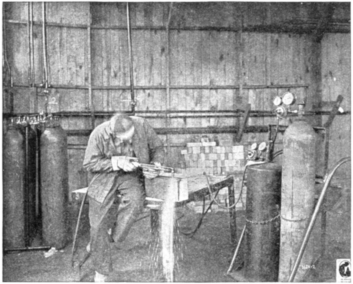
Fig. 80.—The Cutting Torch Eats its Way through Steel of any Size with Remarkable Ease, Leaving a Clean-cut Edge. This View Shows a Cutting Torch in Operation at the Ordnance Welding School, U. S. Army.
(144) An ideal arrangement on the oxygen line for cutting is to have a double or “twin” regulator attached to the oxygen[126] drum, one side of which will do for welding and the other, being high-pressure type, will produce a constant flow of high-pressure gas, suitable for the cutting jet. Then when cutting is done a three-hose torch should be employed. One of its oxygen connections which governs the neutral flame can be connected to the low-pressure regulator, while the oxygen jet should be controlled by the high-pressure regulator, the third connection will furnish the acetylene gas for the preheating flame. However, in place of this three-hose arrangement, most cutting is accomplished by means of a two-hose apparatus, wherein only one hose is used to convey the oxygen from a single regulator to the torch. On such[127] apparatus much trouble is usually experienced in cutting old metals where a great deal of scale is present or in a close place where the torch is apt to get hot.
(145) Many times part of the scale or metal will pop up against the tip and cause the oxygen jet to flicker. This slight variation may cause an excessive pressure of oxygen to be introduced into the preheating flame momentarily, by backing up the oxygen in the cutting jet. This lean mixture of gas will generally flash back instantaneously and will deposit a layer of carbon on the inside of the tip, which causes much annoyance to the operator. This condition is to be found where there is but one oxygen line. In the two-hose arrangement this is entirely overcome, due to the independence of the pressure on each line.
(146) The high-pressure regulator differs from the low-pressure regulator in these respects: The diaphragm, see Fig. 16, is much smaller in diameter, which makes it less sensitive, and of course much stronger. The diaphragm springs are usually much heavier; the nozzle contains a larger opening for passing gas freely without freezing; and to take care of the increased pressure on the line, usually a higher pressure working gauge is added to the regulator. Such a regulator is capable of passing much more gas than the low-pressure type, but as far as being as sensitive and maintaining a constant, absolute flow of gas, its design will not permit it to do so. In cutting, these requisites are not necessary. In welding, however, the delicate adjustment of the flame demands a very sensitive regulator and usually the larger the diameter of the diaphragm the more sensitive the adjustment.
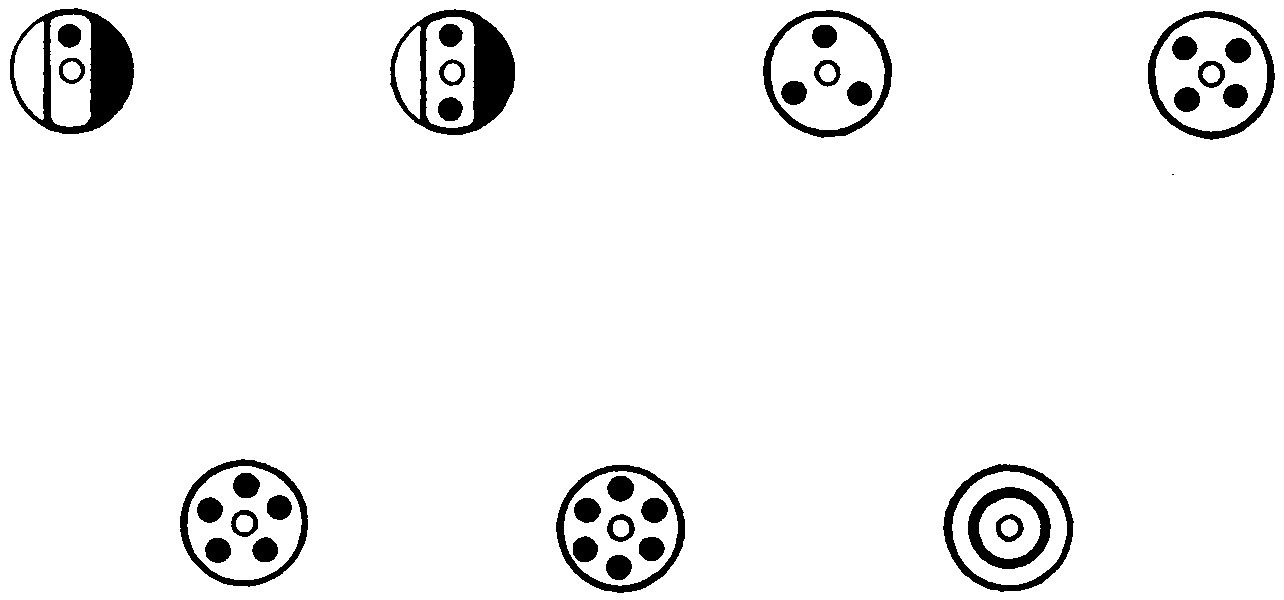
Fig. 81.—End Views of Cutting Tips, Showing Possible Arrangements of Preheating Flames in Regard to Oxygen Jet. The Black Circles Represent the Preheating Flames, which Vary in Number and Arrangement According to the Nature of the Work, the Possible Limit being a Continuous Circle, as Shown. The White Circles Illustrates the Oxygen Jet, which, too, Varies in Size According to the Work.
(147) The cutting torch differs from the welding torch in many respects. The tip itself, when looking at its end, may resemble any one of the views shown in Fig. 81. In the welding torch, but one hole is to be found in the tip;[128] in the cutting tips, two or more holes are to be found. In all cases the center hole passes pure oxygen, whereas in the surrounding holes, both oxygen and acetylene mix and when lighted give a neutral flame. This will hereafter be called the preheating flame. The gases issuing from these openings are controlled by three valves, one of which may have a trigger or lever arrangement for quick action, and it will control the center jet of oxygen which really does the cutting. This is under much higher pressure than the preheating flame. The other two valves will control the oxygen and acetylene gases used for the preheating flame. In lighting such a torch, the acetylene is turned on in the same manner as has been taught when welding, until it just leaves the end of the tip. Then the oxygen valve is opened, which controls the preheating flame, and enough is permitted to pass to produce a neutral flame. As soon as this has been accomplished, the third valve should be quickly opened and held so a moment, to see if the neutral flame has been changed. Generally this operation will deprive the neutral flame of some of its oxygen, and a feather flame, showing too much[129] acetylene and not enough oxygen gas, can be noticed. This will necessitate turning on slightly more oxygen at the torch valve. The third valve is then shut off and the torch is ready to start cutting.
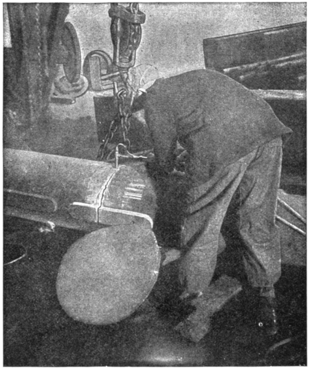
(Courtesy of the General Welding & Equipment Co.)
Fig. 82.—Cutting a Heavy Shaft.
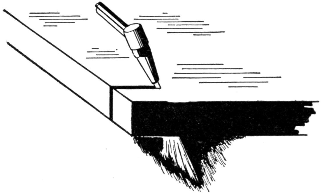
Fig. 83.—Position to Hold Torch in when Cutting Metal.
(148) On small cutting jobs, about as much acetylene pressure is used on the line as there would be if it were a welding job. The oxygen pressure, however, is generally much greater, and a pressure anywhere from ten to two[130] hundred pounds should be used, depending upon the thickness of the metal and the conditions which must be met. In extreme cases where very heavy cuts are to be made, a much higher pressure than has been mentioned should be used, but the limitations given will cover a wide range of work. To start a cut it is necessary to bring the preheating flame in contact with one edge of the metal to be cut and play it there until the metal is red hot. As soon as this condition is reached the torch is held steady—the neutral flame just touching the metal; then the third valve controlling the cutting jet of oxygen is opened. This oxygen, under high pressure, quickly acts upon the hot metal and severs it instantaneously, melting and oxidizing the metal so that it will not flow together, in one and the same operation. As soon as this occurs the torch should be advanced as rapidly as possible in the direction the metal is to be cut. The more rapid the advancement and the steadier the torch is held the cleaner the cut will be; and incidentally, less gas consumed in the execution of the job. In cutting, as in welding, it is always well to give the torch a chance, and when the operator sees much molten metal splashing directly back on the torch, he should change the angle slightly to avoid his apparatus becoming overheated. It has been found that if the cutting[131] torch is held at the angle shown in Fig. 83, the most satisfactory results can be expected.
(149) At the present time only such metals as steel and wrought iron can be successfully cut. When it comes to cast iron no method has yet been discovered to cut it with any degree of success by the oxy-acetylene flame, on account of the high melting-point of the oxide and various other matters. The day is looked forward to, however, when after sufficient time and study has been devoted to this subject, that cast iron can be as successfully cut as any other metal, by introducing another gas or agent to destroy some of the reactions which retard its application at the present time.
(150) The use of the cutting torch in preparing steel work, for welding of large size, plays an important part, in quickly and efficiently “V-ing” out and getting it ready for use. Care should be taken, after its use, to see that the heavy oxide which it leaves is largely destroyed, before any more metal is added.
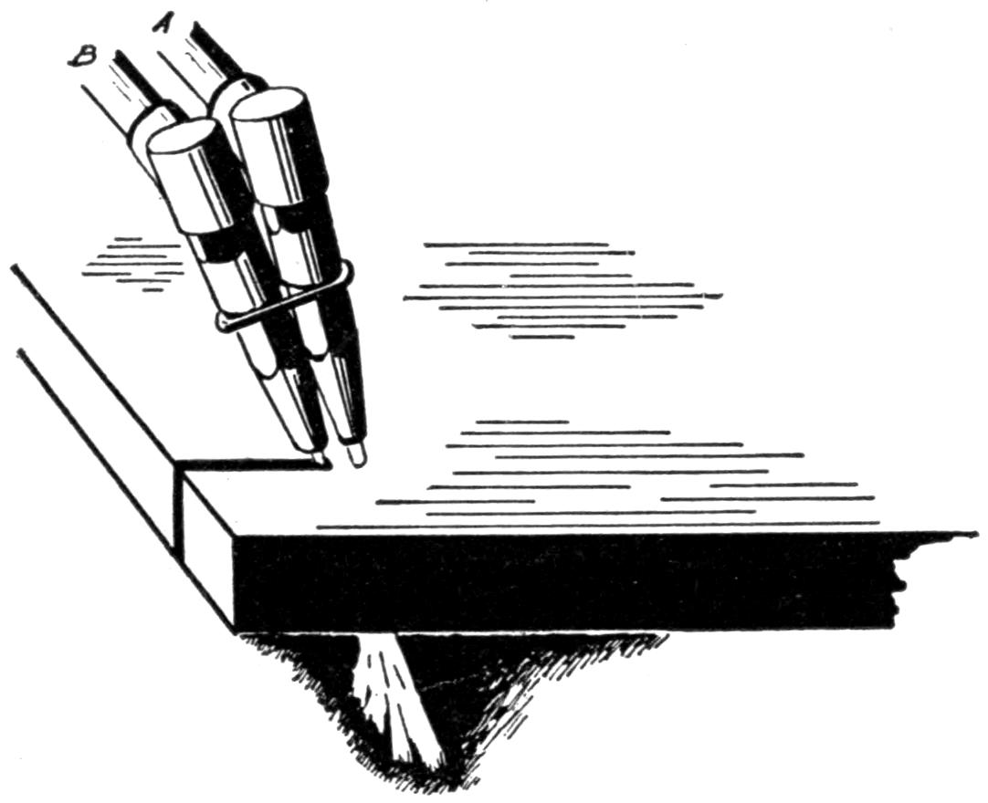
Fig. 84.—Method of Cutting with Two Welding Torches. Torch A is Adjusted so that a Neutral Flame will do the Preheating, while a Fork in the Oxygen Line Supplies Oxygen only to Torch B, and it does the Cutting.
[132]
(151) Frequently the welder has a call for a cutting torch, where none is available, yet an extra welding torch or two may be on hand. If this is the case, two welding torches may be fastened together in such a manner that a temporary job of cutting may be handled. The arrangement shown in Fig. 84 illustrates this point. If no extra welding torch is available, a carbon burning torch or any piece of copper tubing which has a valve in one end, suitable for taking a hose connection, and the other end free to have a welding tip brazed on, can be used in the same manner. The welding torch will give the neutral flame and the extra line of oxygen will do the cutting. It is well to remember that oxygen, no matter under what pressure, cannot be expected to act upon cold metal. A red heat is absolutely necessary. There are various short cuts, it is true, in obtaining this heat, and where a large shaft is to be cut, the operator would not think of playing his torch upon such a piece of metal until it was red hot in the locality in which he wished to start his cut. This would consume too much time and gas. Generally a hammer and cold chisel are brought into play and a slight curl on the metal is obtained as shown in Fig. 85. The moment this becomes red hot, the oxygen jet may be turned on, and the cut commenced. As soon as started, the operator is able to “carry-on” at will.
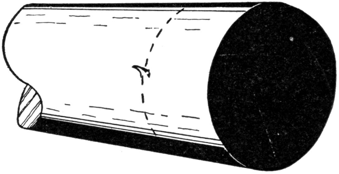
Fig. 85.—When no Edge is Available to Start the Cut on Large Work, Much Time may be Saved by Making a Curl with a Cold Chisel, as Shown.
[133]
(152) An armored hose is generally used on the oxygen line for cutting, as well as on the acetylene line, as there is much more pressure used in cutting than in welding. This type of hose wears much longer and does not kink to the extent that the unprotected hose does. The armor protects both lines from being burned by the melted metal, which is very apt to come in contact with the rubber, were it not protected in some manner.
(153) The question often arises in welding circles, as to why, since the cutting torch contains a series of neutral flames, it would not be just as well to use such a method in welding, as no doubt more heat could be obtained and a greater surface handled. The answer to such a question would be, that the opportunity for oxidation is so great that successful welding could not be expected, although if this were the last means at a welder’s disposal, he would certainly be justified in making a weld in this manner. He should be very careful, however, to see that his extra oxygen supply is completely shut off and that there is no possible chance for that gas leaking into the weld.
(154) To plunge a flame, such as is used in the cutting torch, under water and see it continue to burn while submerged, looks quite marvelous to the average layman. Yet in cutting piling along water fronts this is continually being done. Not only does the torch stay lighted, but it retains much of its efficiency as a cutting tool, and some instances have been recorded where cutting has been accomplished at a depth of thirty feet under the sea. It is true that the water conducts a large part of the heat away very rapidly, but to facilitate such operations, an air line is brought down which ejects air under the torch and clears the water away to some extent, but this is not necessary. In order to explain this phenomenon in a very simple way, it will be stated that nothing will burn unless oxygen is present, and the more oxygen used, up to a[134] certain point, the more rapidly will the burning take place. When submerging the cutting torch, it is presumed that the flame obtains what added oxygen is necessary from the cutting jet and this together with the velocity of the flame and its hydrogen enveloping flame permits the neutral flame to continue burning.
[135]
(155) Those who are familiar with gasoline engines will know that after being used for some time, the impurities in the lubrication oil and in the gasoline, which is continually being burned, will form around the top of the piston and cylinder head in the motor. When enough has been deposited[136] and a few high points become overheated through long running, there will be a metallic knock distinctly heard when an extra strain is being exerted by the motor. This layer of impurities is called carbon and its presence means loss of power. Owing to the construction of most cylinder blocks, it is a very difficult matter to reach this portion of the block without dismantling. This requires skilled labor and means much delay. A method of removing this carbon by the oxygen process has been devised, which will save much time and trouble.
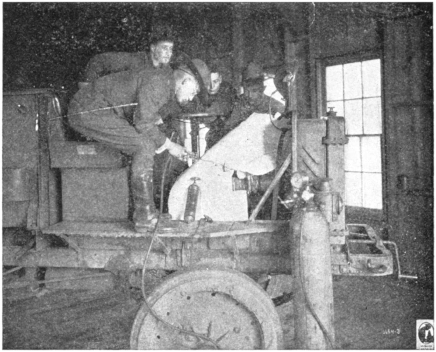
Fig. 86.—Removing Carbon from U. S. Army Truck, by the Oxygen Process, at the Ordnance Welding School.

Fig. 87.—Carbon Burning Apparatus. The Small Copper Tube A is Flexible and can be Bent in any Shape Desired.
(156) To remove carbon from a gasoline engine, first shut off the gasoline in the line and allow the engine to run until all gas has been removed from the carburetor. This is merely a safety measure. If a vacuum feed is used, the vacuum tank is drained, as it would require much time for the engine to consume this amount of gas. The hood of the car is then removed and all parts of the motor on the side where the burning is to be done are covered with asbestos paper or by a heavy piece of canvas which has previously been dampened. This is to keep the sparks from dropping into the apron or oily parts of the machine. Remove the spark plugs and see from the condition of these spark plugs whether the cylinder is dry or oily. An oily cylinder will burn out much more rapidly than when dry. This can be detected very easily from the condition of the spark plugs. It is recommended that only the spark plugs be removed as the removal of the bonnet or any larger portion will require much more oxygen and will not produce as satisfactory results as when the oxygen is introduced through a small opening.
(157) Place the carbon removing apparatus, which consists of the oxygen drum, regulator, a length of hose and carbon burning torch, the latter being made up principally of a shut-off valve and a long length of small copper tubing[137] as shown at A in Fig. 87. Turn on not over twenty-five pounds oxygen pressure as far as the torch, and the apparatus is then ready to use. With the torch inserted through the spark plug hole in number one cylinder, that is, the one nearest the radiator, guide the rise of the piston until it is at the top of the stroke. This means that both intake and exhaust valves are closed. On automobiles where a self starter is used, it will be necessary to use a crank for turning over the motor. With the piston at the top of the stroke and both valves closed, there is only a small portion of the cylinder head to be worked upon and this is the part which has the carbon deposit upon it. All machined surfaces and valve seats are fully protected and will not be subjected to any exposure during the burning. If the cylinder seems very dry, a teaspoon of alcohol or kerosene may be sprayed into it through the spark plug port, to facilitate the clearing of the carbon. If the cylinder is somewhat oily, this is not necessary. A match or burning taper is then held over the hole and a stream of oxygen will carry the flame down into the cylinder and ignite the carbon. As soon as this occurs, a small cracking noise can be heard and the carbon will run around the inside of the cylinder in a heated condition. The part around the valves should be cleaned off first, before going to the inner chamber, as this process does not seem to work very well if performed the other way. A roaring noise will be in evidence and the popping of the carbon from the surface as it frees itself may frighten the operator[138] when attempting his first job, but there is absolutely no danger.
(158) It must be remembered that oxygen itself does not burn, but merely assists the other inflammable material in burning, therefore it is only the carbon which is contained in the cylinder that in this case does the burning. As soon as this is all consumed, there will be nothing else to burn and the sparks will die of their own accord. When this occurs, the operator will shut off his torch, blow the cylinder out with compressed air and replace the spark plug and then proceed with the next cylinder, which he will treat in the same manner. He must be sure, however, that the piston in cylinder number two, or whatever cylinder he is working on, is moved to the top of its stroke and that both valves in that particular cylinder are closed before he starts his burning. After all cylinders have been treated like number one and the spark plugs are in position, the gasoline is turned on (if the vacuum tank has been drained, it is best to fill this), and the motor started, with the exhaust “cut off” open, in order that any loose particles of carbon may be blown out.
(159) While this process is in very common use, and seems to be very simple, there are many who go through the steps without obtaining satisfactory results. It is considered best, if possible, in attempting carbon burning for the first time, to try it on some motor which is about to be overhauled, in order that the results may be studied so that the operator will not go blindly on, without showing some improvement. Many times only the high points are burned out, which will free the motor temporarily of some of its knocks, but within a week or so they will become evident again. He who will become proficient in learning carbon burning should apply himself and study his results.
(160) There are those who consider carbon burning injurious to the motor on account of the high temperature flame[139] which they think is introduced. But it is ignorance as to the working principle of this process that makes them think this. When it is considered that a gasoline motor depends upon a rapid succession of internal explosions for its power, the folly of condemning a process of this nature, where absolutely no actual flame is used, will be seen. It is only the incandescent particles of carbon flying about that give any heat at all. After a cylinder has been burned or decarbonized, the hand can be placed upon it immediately, without any fear of being burned. Those motors equipped with aluminum pistons may be handled in the same way as those of cast iron, and when properly used this method of decarbonization is very satisfactory.
(161) Many times it is asked how often carbon burning is to be recommended. This will all depend upon the type of motor, its condition, and to some extent, upon the lubricating oil and gasoline used, as well as the mileage of the car. If a machine is being run continually, it may be necessary to have the carbon removed about every two months, but conditions will tend to lengthen or shorten this time as the case may be. When the knocks are in evidence, and the loss of power is noticed, it is time for the carbon to be removed, and whether this is one month or two it is an error to continue running the car which is filled with carbon. Invariably the carbon burner is asked by his customer whether carbon burning will regrind valves; this and many other questions can be intelligently answered and explained to the questioner’s satisfaction if a careful study of the process is made.
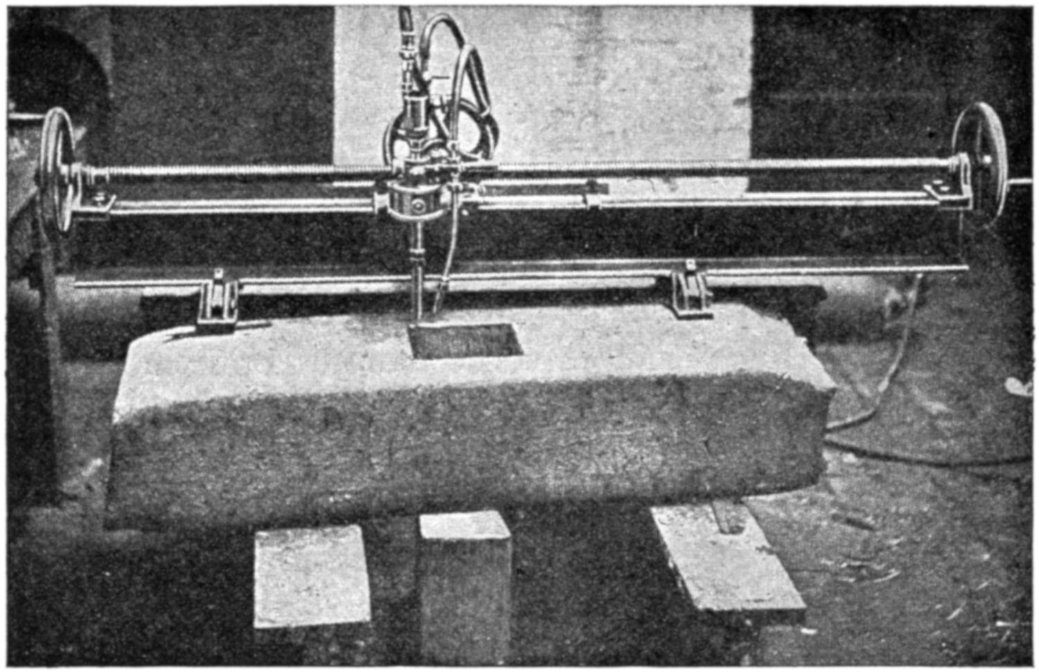
(Courtesy of the British Oxygen Co.)
Fig. 88.—Photograph Showing Square Piece Cut Out of a Steel Block 9 Inches Thick.
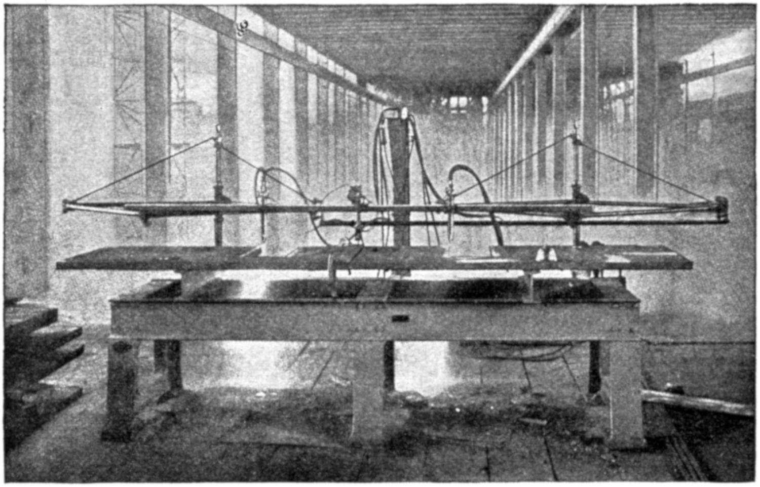
(Courtesy of the Davis-Bournonville Co.)
Fig. 89.—This is an Electrically Driven Oxy-acetylene Cutting Machine for Making Duplicate Cuts on Steel from a Drawing. Dies and many Irregular Forms may be Produced at Low Cost by it.
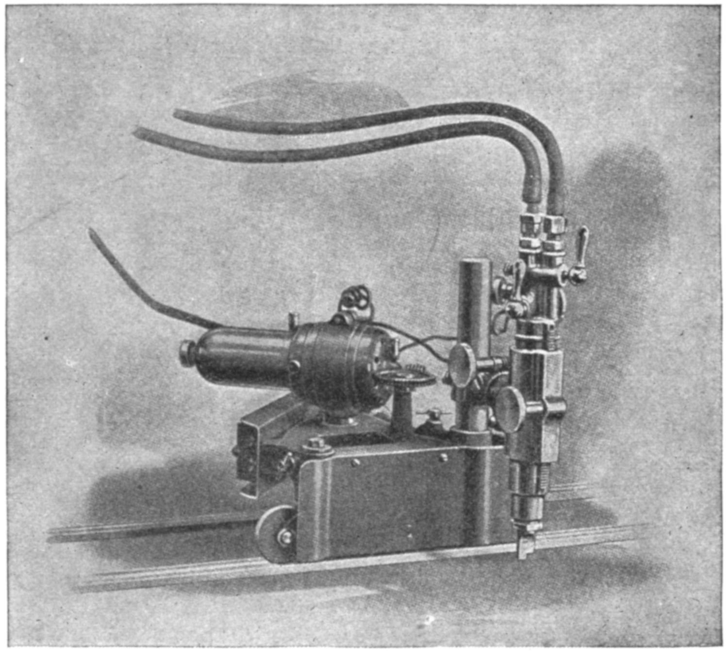
(Courtesy of the Davis-Bournonville Co.)
Fig. 90.—This Shows a Motor-driven Oxy-acetylene Device Particularly Adapted to Cutting Plates or Sheets into Round, Oval, or Irregular Forms with either Straight or Beveled Edges.
(162) In drawing this elementary course in oxy-acetylene
welding to a close, the author wishes to again call attention
to the fact that this course is merely to be considered as a[140-
141]
foundation upon which to build. An effort has been made to
confine the student’s line of thought exclusively to the actual
welding of the various metals and an intimate knowledge of
the tools necessary to accomplish this. Technical terms have
been avoided as much as possible, and history, as well as the
generation of the various gases, have been considered only of
secondary importance and have been purposely omitted.
Many repetitions have been made to place emphasis upon
certain points and methods. It is hoped that the student
who pursues this course if he has been restricted to the use[142]
of only one apparatus will realize that there are many
such on the market, each one of which may have its advantages,
but if the general rules, as outlined, are followed, he
will not have much difficulty or be covered with confusion
if called upon to operate different makes of apparatus for
the first time. If he sees that there is gas pressure on his
lines, he should not hesitate, thereby showing his ignorance
of that particular type of apparatus, rather let him turn on
one valve, and direct the stream of gas toward his nostrils.
He can then readily determine whether it is the fuel gas or
not and knowing that oxygen will not burn he can turn his[143-
144]
fuel gas on and proceed without showing any concern. It
might be said that confidence in one’s self is the keynote of
success, and this is imperative to make an expert welder,
but to the man who studies the flame action on his metals
and appreciates the apparatus to the fullest extent, there is a
very bright future.

Fig. 91.—Quick, Permanent Repairs are Made on Large Supply Trucks in the U. S. Army by its Corps of Trained Welders. This View Shows an Individual Welding Unit in Operation at the U. S. Army (Ordnance) Welding School.
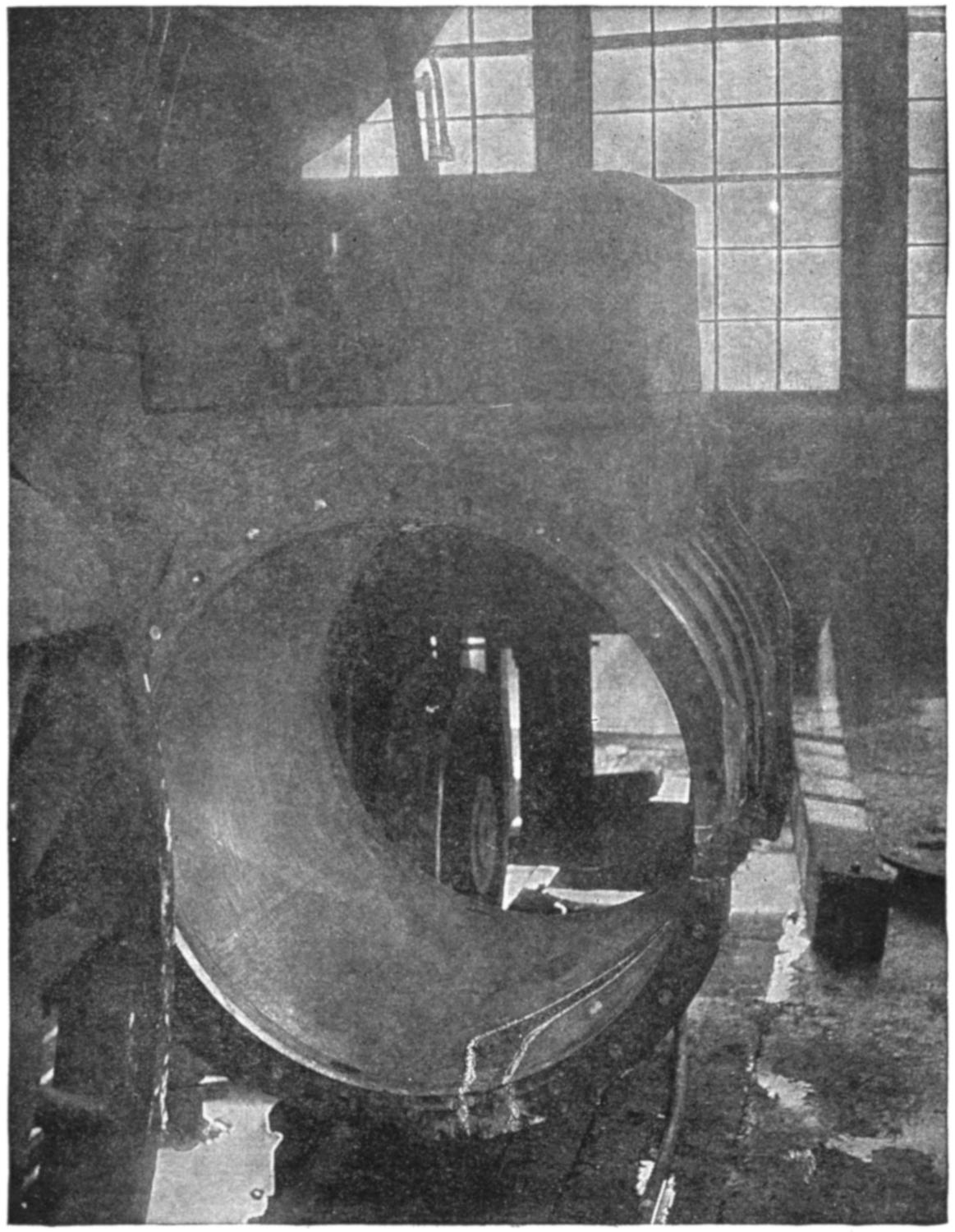
(Courtesy of Ben K. Smith, U. S. Welding Co.)
Fig. 92.—This Cylinder did not Require to be Bored or have any other Machine Work Performed, but was Placed in Service Directly after Welding and has been Serving for over Three Years.
(163) The welder who desires the best results should procure the best apparatus possible to fill his requirements. The cost of such is only of secondary importance, the hazard attached to cheaply constructed apparatus and the loss of gas, time and the execution of faulty work and the depreciation of the welder’s reputation, are matters of vital importance. The supplies too, such as filler-rods and the like, should be obtained only from reliable welding companies who have their own shops in which they may test them. It is false economy indeed, to attempt to save a few cents on filling materials, for many dollars’ worth of time and gas may be lost on account of the failure of the metal added.
(164) There are a few illustrations set forth herein, to show what has been accomplished in the way of machine construction used in adapting the oxy-acetylene process to the requirements of various manufacturers. These will tend to show to some extent what the future has in store for this wonderful process.
(165) It has been rightly stated that oxy-acetylene welding is yet in its infancy. The torches, regulators and in fact all parts of the apparatus are constantly being improved. The process of cutting cast iron must still be solved, so it will again be stated that it behooves those who are interested in this work to apply themselves to the great future in store for them.
[145]
Acetone. A liquid which is capable of absorbing twenty-five times its volume of acetylene gas under normal temperature and pressure. Employed as a solvent in the acetylene cylinder.
Acetylene. An inflammable gas used for welding and cutting.
Acetylene Cylinder. A steel tank filled with porous material and acetone, in which acetylene gas is stored.
Adapter. A brass fitting used to connect regulators to different cylinders.
Alignment. State of being in line.
Alloy. Metal which is added to another metal. A mixture of two or more entirely different metals.
Angle Iron. A steel bar, the cross-section of which forms an angle of 90 degrees.
Asbestos. A fibrous material not affected by fire. Usually supplied in sheets or shredded.
Autogenous Welding. The process of uniting two pieces of metal together by fusing without additional metal being added, and without the aid of hammering.
Babbitted. Lined with Babbitt metal. Generally found in bearings.
Back Fire. The popping out of the torch flame, due to a slight explosion of the mixed gas between the torch tip and the mixing chamber.
Bearing. Support or wearing surface for a revolving shaft.
Bevel. To cut or form at an angle.
Beveled Edge. An edge cut or formed at an angle.
Blowhole. A hole or cavity formed by trapped gas in metal.
Blowpipe. A torch which mixes and burns gases producing high-temperature flames. The term TORCH is given preference in oxy-acetylene welding and cutting.
[146]
Brazing. Uniting metals with brass or bronze by means of heat.
Brazing Wire. A filler-rod of brass or bronze used in brazing.
Butt Joint. A joint made by butting two edges together.
Cap. A metal cover used to protect cylinder valves.
Carbon Blocks. Carbon in block form. Used to assist in building up parts that are to be added. They may be ground to any shape desired.
Carbon Rods. Carbon in rod form. Employed to save holes around which the metal is melted.
Carbonizing Flame. A flame with an excess of acetylene gas.
Contraction. The shrinkage of metal due to cooling.
Cross-bar. Hand screw for adjusting the passage of gas through the regulator.
Cutting Jet. Central jet of oxygen issuing from tip of cutting torch.
Cutting Torch. A torch with one or more heating jets and an oxygen jet, used for cutting metals in the oxy-acetylene process.
Cylinder. A tank containing gas under pressure.
Ductile. That property which permits metal being formed or drawn into different shapes without breaking.
Expansion. Increase in size due to heating.
Filler-rod. A rod or wire used to supply additional metal to the weld.
Fillet Weld. A weld made in a corner.
Flame Propagation. The rate at which a flame will travel.
Flash Back. The burning back of the gases to the mixing chamber or possibly farther.
Flux. Chemical powder used to dissolve the oxides and clean the metal when welding.
Gas. Erroneously applied to acetylene gas alone. Both oxygen and acetylene are in the form of gas.
Gauge. An instrument for measuring pressures of gases.
Generator. A device for manufacturing gas. Usually specified as acetylene generator or oxygen generator.
Grain. The arrangement of the molecules or crystals which make up a metal.
Horizontal Welding. Welding in a level position.
I-beam. A steel bar with the cross-section of an I. Sometimes called EYE BEAM.
Line. Hose or pipe carrying gas.
[147]
Manifold. A header with outlets or branches by which several cylinders of gas may be used in batteries.
Monel Metal. An alloy of copper and nickel.
Nipple. A short piece of pipe.
Overhead Welding. Welding with the torch overhead.
Oxidation. A combination with oxygen.
Oxide. A coating or scale formed by oxygen combining with metal.
Oxidizing Flame. A flame with an excess of oxygen gas.
Oxygen. A non-inflammable gas used in oxy-acetylene welding and cutting.
Oxygen Cylinder. A steel tank for storing and shipping oxygen. Available for commercial work in 100, 200, and 250 cubic-foot sizes. The oxygen is compressed as free gas to 1800 pounds pressure at 68 degrees Fahrenheit.
Peening. Stretching the surface of cold metal by use of the hammer.
Penetration. A thorough welding completely through the joint of the pieces or parts being fused.
Preheating. The heating of a metal part previous to welding. Generally used to prevent strains or distortion from contraction and expansion; also to save gas.
Pool. A small body of molten metal formed by the torch flame.
Puddle Stick. A steel rod flattened at one end, used to break up oxides, remove dirt and build up additional metal. Particularly helpful in welding cast aluminum.
Puddling. The manipulation of the filler-rod or the puddle-stick in such a manner as to break up oxides, remove dirt, and aid in securing a good fusion of the metal.
Reducing Flame. (See Carbonizing Flame.)
Reducing Valve. (See Regulator.)
Regulator. A device for reducing and maintaining a uniform pressure of gas from cylinders, generators or shop lines.
Scale. A coating of oxide on fused iron or steel that breaks off as the metal cools.
Scaling Powder. A name given flux.
Slag. The oxidized metal and scale blown out when cutting.
Soldering. Uniting metals by fusing with a different metal which has a much lower melting-point than the pieces to be joined. The use of a lead, tin and zinc alloy is called soft soldering. Hard soldering is similar to brazing.
Tacking. Fusing pieces together at one or more places.
[148]
Tip. A copper or brass nozzle for a welding or cutting torch.
V. Angle or groove between two beveled edges prepared for welding.
V-block. Block cut out in the shape of a V, or angle iron, used in lining up shafts.
Valve. A device for shutting off the passage of gas.
Vertical Welding. Welding as applied to an upright position.
Welding Rod. Material used to supply additional metal to the weld. (See Filler-rod.)
[149]
Note.—In order to determine whether the student is obtaining the information desired it is sometimes thought fitting to give written examinations. These serve as an index as to what the student has learned and what he has not. They also let the instructor know whether he is making every point clear in his training.
The following questions fit in with each chapter or part thereof and are merely a suggestion for the instructor who has no course of training outlined. With one or two exceptions all answers to these questions may be found within the manual. There are a few misleading questions purposely inserted to see if the student is thinking for himself.
1. Name the different classes into which oxy-acetylene welding apparatus may be divided and explain the principles upon which this classification depends.
2. Illustrate by line sketches the various locations of the mixing chambers for the oxygen and acetylene gases in welding torches.
3. (a) Where is the logical location for the mixing chamber in welding torches employed in automobile and tractor repair work?
(b) Give reasons for so thinking.
4. How is the torch and the welding tips treated after repeated “flash-backs” have taken place?
5. Describe briefly the working principles of a regulator and illustrate with a simple sketch.
6. Explain the difference between high and low-pressure regulators.
7. (a) Can acetylene regulators be interchanged with oxygen regulators with perfect safety? Explain why.
(b) How is it possible, in majority of cases, to distinguish in a very[150] simple manner, between oxygen and acetylene regulators, when no gauges are attached?
(c) Why does this difference exist?
8. (a) Why should all tension upon diaphragm springs be removed before admitting gas under pressure to the regulator?
(b) Can a regulator which has been abused in this manner be repaired?
(c) What can be employed as a fitting substitute for gallilith?
9. Explain why the high-pressure gauge on the acetylene regulator cannot be used as an index to the contents of the attached cylinder of gas in exactly the same manner as the oxygen high-pressure gauge.
10. Why is glycerine used as a substitute for oil when regrinding torch valve-seats with emery powder, and with lead-oxide in the caulking of leaky joints along the line?
1. (a) Under what pressure is oxygen gas received in the cylinders used commercially?
(b) Does this pressure vary to any great extent with changes in temperature?
2. (a) Under what pressure is acetylene gas received in the cylinders used commercially?
(b) Does this pressure vary to any great extent with changes in temperature?
3. (a) In setting-up apparatus for the first time, or in attaching regulators to new cylinders, what precaution should be observed regarding cross-bar on regulators before the gas is turned on?
(b) Where should the operator stand when turning on the gas?
4. (a) How much pressure should be placed on the oxygen hose, when the torch-valves are closed, before starting to operate with a medium-sized tip?
(b) How much pressure should be placed on the acetylene hose, when the torch-valves are closed, before starting to operate with a medium-sized tip?
5. (a) After both the oxygen and acetylene gases are in the line hoses as far as the torch, which valve on the torch is opened first in order to light?
(b) What would happen if the other torch-valve were opened first?
[151]
(c) What would likely occur if both valves were opened before torch was lighted?
6. (a) How is it possible, when lighting torch, to determine whether enough pressure is on the acetylene line without looking at gauge?
(b) How is it possible, in the case of oxygen pressure?
7. (a) What is meant by a neutral flame?
(b) How hot is a neutral oxy-acetylene flame?
(c) Is the temperature of a neutral flame the same whether large or small tip is used?
8. (a) If too much acetylene gas is used, how will the flame be affected?
(b) What action will this have on the weld?
9. (a) If too much oxygen gas is used, how will the flame be affected?
(b) What action will this have on the weld?
10. (a) Explain briefly how apparatus is shut-off, when not to be used for several hours or more.
(b) Why should particular care be taken to see that acetylene cylinders are tightly closed when empty?
(c) What action does oxygen have on oils and greases?
1. (a) How is it possible to distinguish cast iron from such metals as malleable iron?
(b) From semi-cast iron?
(c) From cast steel?
2. (a) What kind metal is used in making “filler-rod” used in the welding of cast iron?
(b) What general rule can be laid down as to the relation of the metal in the “filler-rod” to the metal to be welded?
3. (a) What are the characteristics of good cast iron “filler-rods”?
(b) Can piston rings and other small scraps of cast iron be used successfully as “filler-rods”? Explain why.
4. (a) What is the purpose of a flux?
(b) Is a flux used in the welding of cast iron?
5. (a) Name one formula for making a cast-iron flux?
(b) How often is the flux applied, and by what means?
(c) In what condition are fluxes kept when not in use?
[152]
6. (a) How should the flame be held in the welding of all cast iron?
(b) When and how is the “filler-rod” added to the weld?
7. (a) Name the one principal cause of blow-holes and hard spots in the weld.
(b) Mention some of the others.
8. (a) When is it advisable to grind, or “V” out, the ends of the pieces to be welded?
(b) When is it not advisable?
9. (a) Does the application of heat cause contraction or expansion in metals?
(b) Are there any excepts to this rule? Name one.
10. (a) Were two cast-iron bars measuring 2 × 12 inches and ¹⁄₂-inch thick, to be welded, end to end, what precaution should be observed in laying out, if the finished job is to measure just 24 inches long?
(b) In what respect would this problem differ were the bars only 6 inches originally and the finished job to measure 12 inches overall?
(c) Is the action of the metal in the weld a constant, or a variable quantity depending upon the length of the bar in this problem?
11. (a) How could a spoke, broken midway between the hub and rim, of a 24-inch, 4-spoke wheel (otherwise intact) be welded without preheating? (Use a sketch if necessary to make method clear.)
(b) If a wheel of like size were broken only in the rim, midway between spokes, explain procedure in welding without preheating.
(c) Same sized wheel, broken only in hub;—can weld be made without preheating? Give reasons for so thinking.
(d) Were breaks (a), (b) and (c) all present in same wheel, with rim fracture on opposite side of adjoining spoke from break in hub, should welding be started at rim or hub? Why?
12. (a) In the building up of broken or missing teeth in cast-iron gears, what procedure is necessary when no carbon blocks are available for forms?
(b) If certain carbon centers from dry cell batteries are obtainable how should they be treated before allowing molten metal to come in direct contact with them?
[153]
(c) What very important point must be uppermost in mind when dental work on gears is being done?
(d) Explain precautions taken in allowing work of this nature to cool.
13. (a) Realizing that hard spots occur in most welds executed by the new welder and having learned the cause of their presence and how to overcome them, would it not be possible to utilize this process for hardening parts which were subject to much wear and little strain? Explain procedure.
(b) Why is it necessary to preheat such pieces as the following before the weld is attempted; broken water-jackets on gas-engine cylinders, usually brought about by freezing, and holes or cracks in crank cases, caused by the loosening of a connection rod; when lugs on the same cylinder, the arms on the same crank case can be welded without preheating, and ofttimes without even dismantling the motor?
14. Describe fully the manner in which two cast-iron bars measuring 1 × 6 inches and 24 inches long, are welded end to end, citing preparations, precautions, and the procedure and materials necessary to execute and carry the weld through to a cool state.
Note.—Both gases are in the line hoses as far as the welding torch.
15. (a) Are water jackets on cast-iron cylinder blocks welded in a cold, or a preheated condition?
(b) Is this true under all conditions?
(c) If a crack were found in the combustion head of a cylinder block and the entire water jacket and cylinder were cast in one, how should this job be prepared in order to make a successful weld?
(d) In welding a broken lug on the base of a cylinder block how should lug appear after weld is cold?
[154]
1. Describe the operation, step by step, taken to set up an oxy-acetylene welding plant, from the assembling of the parts, right through, until a neutral welding flame is obtained. (If a sketch, with the gas cylinders and parts numbered 1, 2, 3, etc., will assist in making description clear, it may be used.)
2. (a) Is it desirable to have a planed metal, or a brick-top table for welding purposes?
(b) Explain why.
3. Outline and describe briefly, a simple method of building a popular type of welding table.
4. (a) What is the name and style of bricks used in the welding shop?
(b) Name at least three purposes for which these bricks are used.
5. (a) Why does an emery wheel play such an important part in the oxy-acetylene welding industry?
(b) Why is it desirable to have a flexible shaft attachment for the emery wheel, if possible?
(c) Name some of the important things a flexible shaft attachment is used for in the preparation and finishing of welds.
6. (a) In what kind of containers is retort cement purchased in the commercial world?
(b) Where is retort cement used in the welding shop?
(c) How does it differ from the ordinary clay or putty?
7. (a) Why should a blacksmith forge be added to the welding shop equipment if one is obtainable?
(b) What two important tasks is a forge used for in the welding shop?
8. (a) It is essential that several pails of water be located throughout the shop; why should this be necessary?
(b) Mention a few instances where water is required in the welding shop.
9. Explain fully why great care should be exercised in ventilating a shop where commercial welding is being done.
10. (a) Describe one simple method of constructing a flux box.
(b) What advantages has this type of container?
[155]
1. What is the best method of locating a leak in either the oxygen or acetylene lines?
2. If a leak were found in a ground seat, how could it be stopped if the nut on the coupling had been screwed up as far as possible?
3. Name one method of attaching connections to hoses so that they will not blow off or pull off when pressure is applied.
4. How could either an oxygen or acetylene hose that had been burned or otherwise injured, be repaired to withstand the gas pressure?
5. How could regulator be operated if the cross-bar for applying pressure upon the diaphragm springs were lost?
6. (a) What procedure would be necessary to make connection if cylinder were supplied with an adaptor which would not fit the regulator connection and it could not be coupled up directly?
(b) Realizing that all cylinder connections about a regulator are generally supplied with a ¹⁄₄-inch taper pipe thread, why do all manufacturers solder them in?
7. Explain why oxygen high-pressure gauges are constructed with a loose back and a solid front.
8. (a) Where is the first place to seek trouble in a gauge if it leaks?
(b) Can such leaks be repaired?
(c) Describe method.
9. If either a high-or low-pressure gauge were injured beyond the repair state how could welding plant be kept in operation without it?
10. (a) What would be the trouble, in shutting off a welding plant, if there were a reading on the high-pressure gauge and none on the low-pressure gauge, after permitting gas to escape from the hose?
(b) How could the reading on this gauge be brought back to zero?
1. (a) Is the welding of steel more or less difficult than cast iron?
(b) Explain why.
2. (a) Why is the choice of the welding tip so important when working on steel?
[156]
(b) What will result if the tip is too large?
(c) If too small?
3. (a) Why is the choice of a “filler-rod” of a correct size so important for steel welding?
(b) What will happen if the “filler-rod” is too large?
(c) If too small?
4. (a) What kind of a “filler-rod” is used in welding steel?
(b) Give a general rule covering relation of “filler-rod” to the metal being welded in all cases, but one or two.
(c) Name one exception.
5. (a) Is a flux (or scaling powder) necessary in welding steel?
(b) Explain why.
6. (a) How is the flame adjusted for steel welding?
(b) What kind of a flame is generally used in finishing steel work?
(c) Why is this done?
7. (a) How is the flame held when executing a steel weld?
(b) How is the “filler-rod” held when making a steel weld?
8. (a) Is it necessary to “V” out on steel the same as on cast iron?
(b) Explain why.
9. (a) Is a steel weld as strong as the original metal if not built up?
(b) Explain why.
10. (a) Is the same provision made for expansion and contraction on steel as on cast iron?
(b) Give reasons for so thinking.
11. (a) What is meant by a “crater” in steel welding?
(b) How are they removed from the weld?
12. (a) What are some methods and marks of distinguishing steel from other metals?
(b) How is cast steel distinguished from cast iron?
13. (a) Name some of the qualifications of a good “filler-rod” for mild steel welding.
(b) In what manner does the “filler-rod” differ for the alloyed and high-carbon steels?
14. (a) In bringing the neutral flame in contact with the metal on a[157] steel weld, should the cone bend and spread on the surface, or just lick it?
(b) Explain why.
15. (a) What is the principal cause for hard spots in steel welds?
(b) What causes some of the others?
16. (a) Is it rolled steel or cast steel that does not expand when heated?
(b) Name one other metal that does not expand when heated.
17. (a) Why are welds more difficult on sheet iron and steel than on some of the heavier pieces?
(b) What can be used as a “filler-rod” on sheet metal work?
18. (a) What difficulty is generally encountered, when making a long weld like on a steel tank?
(b) How can this be overcome?
(c) Why do the open ends on sheet steel welds overlap in welding when same class of work on cast iron separates?
19. (a) What causes steel welds to carbonize?
(b) What usually causes a burnt steel weld?
20. Describe fully how a broken automobile frame can be welded and re-enforced to make it stronger than originally.
21. (a) What kind of a “filler-rod” is used in welding cast steel?
(b) Is a flux used?
22. (a) What kind of a “filler-rod” is employed when welding cast iron to steel?
(b) What kind of a flux is used?
23. (a) Can springs be successfully welded?
(b) State reasons.
24. (a) Why are crank-shaft welds so hard to execute successfully?
(b) What kind of a “filler-rod” is used for best results on most crank-shafts?
(c) What points does the welder consider when deciding whether a weld of this nature is advisable?
25. (a) Briefly describe the method of building up crank-shaft bearings that have been worn down.
[158]
(b) What are some of the precautions taken in work of this kind?
26. (a) When automobile propeller shafts and rear axles break, it is generally adjoining the square end. Is it advisable to weld this short piece on?
(b) What is the correct procedure in a case of this kind?
27. (a) If a case-hardened ring-gear is to have its teeth built up or new ones added, how is it handled after welding?
(b) Should all case-hardened work be so treated after welding?
28. (a) In welding two pieces of metal, one of which is considerably lighter than the other, how is the flame held in order to bring both pieces to a fusion at the same time?
29. (a) If a steel weld were to break in the line of weld, how should it be prepared if it is to be rewelded?
(b) Does this procedure apply only to steel?
30. Were a hole 6 inches square in a sheet of steel to be welded up without preheating, what would be the approximate size of the patch necessary and how would it be prepared, in order to take care of the expansion and contraction strains?
31. (a) Why should a steel weld of any kind be executed as rapidly as possible?
(b) What will happen if steel is kept in a heated condition too long?
(c) Why should a change be in evidence under these conditions?
32. (a) Explain what is meant by a “dished” patch, for boiler or thin armor plate?
(b) Draw such a patch.
(c) How is a patch of this nature prepared?
33. (a) What is meant by a “corrugated” patch for boiler or thin armor plate?
(b) Sketch such a patch.
(c) How is this kind of a patch prepared?
34. (a) What advantages has a “corrugated” patch over one that is “dished”?
(b) Where are “corrugated” patches used extensively?
35. (a) How are boiler flues prepared for re-tipping?
[159]
(b) Sketch a simple jig for holding such pieces in place for welding.
36. (a) Describe how lengths of various sized pipe can be welded together end to end.
(b) What precautions are necessary when executing such welds?
37. (a) When welding large steel castings why is it almost always advisable to preheat the work?
(b) Why is preheating so necessary on vanadium and other alloyed steels?
38. Why is it desirable to chip out the sand and thin scale formations, in and around blow-holes in steel castings before filling in?
39. (a) Why do the majority of good welders bend their steel “filler-rods” at right angles about 6 inches from the end?
(b) Why isn’t this being done on cast iron?
40. (a) What advantage is there in making a vertical weld from the top down, rather than starting from the bottom and working up?
(b) In welding overhead why is it so important that the work be in a molten state before adding the “filler-rod”?
(c) In overhead welding, why doesn’t the metal drop when in a molten state?
1. Explain fully which parts of an oxy-acetylene cutting plant are different from a welding unit.
2. (a) If there is a difference in either of the regulators, mention which one it is.
(b) What is the difference?
(c) Why is it necessary?
3. (a) Is it possible to weld with a cutting torch?
(b) What precaution is necessary if this is done?
(c) Why isn’t this process used?
4. Explain how cutting can be done with the welding torch if necessary.
5. (a) In cutting by the oxy-acetylene process, which does the cutting, the oxygen jet or the neutral flame?
(b) What action has the oxygen jet on the metal?
(c) What part does the neutral flame play in cutting?
6. Can oxygen or acetylene under sufficient pressure be made to cut individually? Explain fully.
[160]
7. Why is it specially important that armored hose be used on the oxygen line when making heavy cuts?
(Give at least two reasons.)
8. (a) How is a cutting torch lighted? Describe in detail.
(b) How is cut started on metal?
(c) How is torch held in regard to metal being cut?
9. (a) Is it possible to successfully cut cast iron?
(b) Wrought iron?
(c) Cast steel?
(d) Rolled steel?
10. (a) Cutting can be done under water with ordinary cutting apparatus; why doesn’t the flame go out when submerged?
(b) What additional equipment is generally used in underwater cutting?
1. Explain as fully as possible the chief characteristics of a good “filler-rod” for brass welding.
2. (a) Is a flux used in welding brass?
(b) What is one way of making a good flux for brass?
3. (a) What kind of a flame is used in brass welding?
(b) Why?
4. (a) In what position is the flame held in welding brass?
(b) How should the “filler-rod” be held?
5. (a) Is it advisable to “V” out or burn off the ends of brass work to be welded?
(b) Explain why.
6. (a) What causes the dense white fumes to appear when fusing brass?
(b) What is cause of brass welds being porous?
7. Why should brass work not be disturbed when red hot?
8. What is the most difficult part of brass welding as a whole?
9. Why are brass welds generally cooled in water as soon as fusion is completed?
10. Why is it difficult for the beginner to weld heavy pieces of brass?
[161]
1. (a) Can malleable iron be successfully welded?
(b) What is the most successful method of joining two pieces of malleable iron?
2. What are three methods of detecting malleable iron?
3. (a) What kind of “filler-rod” is used on malleable iron?
(b) Are “filler-rods” of malleable iron satisfactory?
(c) What kind of flux is used on malleable iron work?
4. (a) How is a malleable iron casting prepared for welding?
(b) How hot should work be, previous to adding “filler-rod”?
(c) What will occur if too much heat is applied?
5. (a) In what respect does the adjustment of the flame differ on malleable iron from that of cast iron and steel?
(b) How is the flame held in relation to the work?
(c) Does the flame come in direct contact with the “filler-rod”?
6. (a) Is more, or less, surface covered by the “filler-rod” on malleable iron than on cast iron?
(b) Why?
7. (a) How should malleable iron be cooled?
(b) Is this the same as in welding brass?
8. On what part of machinery does a welder generally expect to find malleable iron castings?
9. Explain carefully how a malleable iron automobile, axle or transmission, housing that has been cracked or broken, can be re-enforced so that it will be stronger than ever.
10. Describe very briefly how malleable iron is made and in what respect it differs from cast iron when cold, and also when under the influence of the oxy-acetylene flame.
1. (a) Explain what is meant by carbon burning.
(b) In what respect is it used extensively?
2. (a) Will oxygen gas burn alone or does it merely aid combustion?
(b) Will carbon in a free state burn?
3. (a) Why is it advisable to remove only the spark plugs and not[162] the entire valve cap or “bonnet” when burning carbon in a gas engine?
(b) Can it be done either way?
4. (a) Does it make a difference if the carbon is hard and dry in the cylinder?
(b) What will help in such cases?
5. (a) If the cylinder is rather oily does this make a difference?
(b) Does the presence of oil aid or retard combustion?
6. (a) What precautions are necessary before carbon burning is attempted?
(b) How is asbestos paper used in carbon burning?
(c) Name a good substitute for asbestos paper when carbon burning.
7. (a) Is there any danger of warping the valves and overheating the cylinder and piston when burning carbon?
(b) What is the effect of carbon burning on aluminum pistons?
8. (a) What pressure is used on the oxygen line for carbon burning?
(b) Will carbon burning re-grind valves?
9. (a) How long should the burning be done?
(b) How often is carbon burning recommended for a gas engine?
(c) If there are any carbon particles or sand left in the cylinder after burning is done how are they removed?
10. Describe how the carbon is removed from a four-cylinder engine, paying particular attention to details such as lighting, which part of the head the torch is played on first, what does the burning and where the carbon goes.
1. (a) What is meant by preheating as applied to the oxy-acetylene welding industry?
(b) What are several fuels which can be used very successfully for preheating?
2. Name the three principal reasons why parts to be welded are generally preheated.
3. (a) Why is charcoal considered the best preheating agent for general welding?
(b) Why should it not be used to any great extent in closed rooms during the winter months?
[163]
(c) If used during the winter what precautions are observed?
4. (a) Mention two materials which are used extensively for building up ovens and doing the preheating.
(b) What kind of brick is used?
5. (a) How much should cast iron be preheated?
(b) Brass or bronze?
(c) Aluminum?
6. Sketch and describe how a temporary brick preheating oven should be built, giving all dimensions, such as: length, width and height and reasons for them.
7. Explain how a cylinder block with a broken water jacket is set up for preheating; how oven is built for charcoal fire; how fire is started; how block is protected while welding and how it is returned to a cold state.
8. (a) What precautions are necessary in setting up and preheating aluminum?
(b) If piece is to be turned while in the fire, what provision is made in building up oven?
9. In which cases is preheating absolutely necessary in order to make a satisfactory weld?
10. (a) Give a sketch showing a preheating torch for use on illuminating gas and compressed air, which can be constructed very easily.
(b) Why are preheating torches not popular for general welding?
(c) Where are they used in numbers?
1. (a) Is the welding of aluminum, more or less difficult than such metals as cast iron and steel?
(b) Explain why.
2. (a) Name the two methods of making aluminum welds.
(b) Can they be combined?
(c) Why?
3. (a) What kind of a “filler-rod” is used in welding aluminum?
(b) Is a flux used? Why?
4. (a) Is a cast or drawn “filler-rod” preferred?
(b) Name the two important metals which should be present and the percentage of each in the “filler-rod.”
[164]
5. (a) How should the flame be adjusted for aluminum welding?
(b) How is the flame held in relation to the work?
6. (a) How is the “filler-rod” added?
(b) In what respect does this differ from all other metals?
(c) Why can this be done?
7. (a) Name the principal characteristics of aluminum with regard to heat.
(b) What other metal acts in a similar manner?
8. (a) Is it necessary to “V” out aluminum for the same reasons as other metals?
(b) Explain why.
9. (a) Will an aluminum welding be as strong as the original?
(b) Give reasons.
10. (a) What kind of a tool is used to aid in making an aluminum weld by most welders?
(b) How is such a tool made?
11. (a) What kind of files are used to finish aluminum welds?
(b) In what respect do they differ from the ordinary kind?
12. (a) In which hand is the welding torch held in aluminum work?
(b) In which, the “filler-rod”?
(c) The puddle stick?
13. (a) What materials are used to “back-up” aluminum work for preheating?
(b) Describe fully how aluminum is “backed-up” previous to preheating, in order to prevent the collapse of metal while welding.
14. (a) How quick does the heavy coating or aluminum oxide form on a clean hot piece of aluminum?
(b) Will the metal flow together when this oxide is present?
(c) How is it overcome?
15. (a) Is it advisable to weld aluminum from one side only or from both sides?
(b) Why?
16. In preheating aluminum with charcoal, what precautions are[165] taken in setting up; in starting the fire; during the welding operation, and in cooling the piece?
17. (a) Are preheating torches played directly on aluminum work?
(b) What kind of an oven is used?
18. (a) Is it necessary to heat the whole of an aluminum crank-case if one part has to be preheated?
(b) Give reasons.
19. (a) Are clamps used to hold parts in place on preheated aluminum?
(b) Explain why.
20. When starting to weld a cold piece of aluminum, the flame is brought in contact with the work and held there much longer than on a similar size piece of steel before any apparent change occurs. How is this accounted for, knowing that aluminum has a much lower melting point that steel?
21. Explain fully why it is necessary to employ greater speed in the welding of aluminum than on any other metal?
22. (a) What is retort cement?
(b) How does it differ from ordinary clay?
(c) For what purpose is it used in aluminum welding?
23. (a) When performing an aluminum weld by the puddle system, is the welder dependent upon the flame, the “filler-rod” or the puddle stick, for the fusion of the metal?
(b) Give explanations.
24. (a) What method of welding is used when executing a vertical weld on aluminum?
(b) Why isn’t the other method used?
(c) Is the vertical welding of aluminum to be avoided?
25. (a) Can aluminum welds be made overhead?
(b) Explain why.
26. (a) Is the same method used on aluminum as in cast iron in welding from the closed end, toward the open?
(b) Is this procedure necessary on preheated work?
27. (a) If a suspension arm, of a “U” type, on an aluminum crank[166] case were to break about 3 or 4 inches from the body of the case, could it be welded in place without dismantling the motor?
(b) Explain in detail how such an arm should be welded.
28. Due to the contraction and expansion, it is very difficult to have the bolt hole, in the end of an aluminum suspension arm that has been welded, return exactly to its former position. How is this difficulty provided for?
29. (a) Should a section of an aluminum crank case be missing, would it be advisable to build up a new part with the “filler-rod” or to cast a new part in a mold and then weld it in?
(b) Under what conditions should the above be done?
30. (a) If it were found that an aluminum crank case after being welded, had one corner about ¹⁄₈-inch lower than the rest of the case and it had not affected any of the bearings, could it still be reclaimed?
(b) Give procedure.
[167]

For convenience a list of the Wiley Special Subject Catalogues, envelope size, has been printed. These are arranged in groups—each catalogue having a key symbol. (See special Subject List Below). To obtain any of these catalogues, send a postal using the key symbols of the Catalogues desired.
1—Agriculture. Animal Husbandry. Dairying. Industrial Canning and Preserving.
2—Architecture. Building. Masonry.
3—Business Administration and Management. Law. Industrial Processes: Canning and Preserving; Oil and Gas Production; Paint; Printing; Sugar Manufacture; Textile.
CHEMISTRY
4a General; Analytical, Qualitative and Quantitative; Inorganic; Organic.
4b Electro- and Physical; Food and Water; Industrial; Medical and Pharmaceutical; Sugar.
CIVIL ENGINEERING
5a Unclassified and Structural Engineering.
5b Materials and Mechanics of Construction, including; Cement and Concrete; Excavation and Earthwork; Foundations; Masonry.
5c Railroads; Surveying.
5d Dams; Hydraulic Engineering; Pumping and Hydraulics; Irrigation Engineering; River and Harbor Engineering; Water Supply.
5e Highways; Municipal Engineering; Sanitary Engineering; Water Supply. Forestry. Horticulture, Botany and Landscape Gardening.
6—Design. Decoration. Drawing: General; Descriptive Geometry; Kinematics; Mechanical.
ELECTRICAL ENGINEERING—PHYSICS
7—General and Unclassified; Batteries; Central Station Practice; Distribution and Transmission; Dynamo-Electro Machinery; Electro-Chemistry and Metallurgy; Measuring Instruments and Miscellaneous Apparatus.
8—Astronomy. Meteorology. Explosives. Marine and Naval Engineering. Military. Miscellaneous Books.
MATHEMATICS
9—General; Algebra; Analytic and Plane Geometry; Calculus; Trigonometry; Vector Analysis.
MECHANICAL ENGINEERING
10a General and Unclassified; Foundry Practice; Shop Practice.
10b Gas Power and Internal Combustion Engines; Heating and Ventilation; Refrigeration.
10c Machine Design and Mechanism; Power Transmission; Steam Power and Power Plants; Thermodynamics and Heat Power.
11—Mechanics.
12—Medicine. Pharmacy. Medical and Pharmaceutical Chemistry. Sanitary Science and Engineering. Bacteriology and Biology.
MINING ENGINEERING
13—General; Assaying; Excavation, Earthwork, Tunneling, Etc.; Explosives; Geology; Metallurgy; Mineralogy; Prospecting; Ventilation.
Inconsistencies have not been standardised, except as mentioned below.
Changes made:
Illustrations have been moved out of text paragraphs.
Some obviously missing punctuation has been inserted, some unnecessarily repeated words and unnecessary punctuation have been deleted, some obvious minor typographical errors have been corrected silently.
The paragraph numbers have been standardised to bold face numbers.
Page 37: It is quite necessary that these torch valves closed ... changed to It is quite necessary that these torch valves are closed ....
Page 48: ... remove the guage from the regulator ... changed to ... remove the gauge from the regulator ....
Page 169: (Hose) clamps in reparing ... changed to (Hose) clamps in repairing ....